

Panasonic WV-CU20, WJ-NT204 User Manual
ONON
OFFOFF
POWERPOWER
WJ-NT204
(Transmitter)
WV-CU20
WJ-NT204
(Receiver)
LAN / WAN
LAN / WAN
LINK/
10BASE-T
100
BASE-TX CONNECT ACT
LOW HIGH
RING.VOL
Network Interface Unit WJ-NT
POWER
ON
OFF
LINK/
10BASE-T
100
BASE-TX CONNECT ACT
LOW HIGH
RING.VOL
Network Interface Unit WJ-NT
POWER
ON
OFF
ESC
MENU
AF NEAR FARTELE WIDE
Remote Controller WV-CU20
123
456
7809
12345
#
STEP 1
DIAL
PRESET SET
QUICK
STEP 2 STEP 3
CALL
REDIAL
DELETE
ENTER
AUDIO MUTE
ALM ACKVIDEOSWITCH
ONE TOUCH DIAL
AUTO/MANU
SITE
Network Interface Unit
Operating Instructions
Model No. WJ-NT204
WV-CU20
Before attempting to connect or operate this product,
please read these instructions carefully and save this manual for future use.

IMPORTANT SAFETY INSTRUCTIONS
1) Read these instructions.
2) Keep these instructions.
3) Heed all warnings.
4) Follow all instructions.
5) Do not use this apparatus near water.
6) Clean only with dry cloth.
7) Do not block any ventilation openings. Install in accordance with the manufacturer's instructions.
8) Do not install near any heat sources such as radiators, heat registers, stoves, or other apparatus (including amplifiers) that produce heat.
9) Do not defeat the safety purpose of the polarized or grounding–type plug. A polarized plug has two
blades with one wider than the other. A grounding type plug has two blades and a third grounding
prong. The wide blade or the third prong are provided for your safety. If the provided plug does not fit
into your outlet, consult an electrician for replacement of the obsolete outlet.
10) Protect the power cord from being walked on or pinched particularly at plugs, convenience receptacles,
and the point where they exit from the apparatus.
11) Only use attachments/accessories specified by the manufacturer.
12) Use only with the cart, stand, tripod, bracket, or table specified by the manufacturer, or sold with the
apparatus. When a cart is used, use caution when moving the cart/apparatus combination to avoid injury
from tip-over.
S3125A
13) Unplug this apparatus during lightning storms or when unused for long periods of time.
14) Refer all servicing to qualified service personnel. Servicing is required when the apparatus has been
damaged in any way, such as power-supply cord or plug is damaged, liquid has been spilled or objects
have fallen into the apparatus, the apparatus has been exposed to rain or moisture, does not operate
normally, or has been dropped.
2
Caution:
Before attempting to connect or operate this product,
please read the label on the bottom.
CAUTION
RISK OF ELECTRIC SHOCK
DO NOT OPEN
CAUTION: TO REDUCE THE RISK OF ELECTRIC SHOCK,
DO NOT REMOVE COVER (OR BACK).
NO USER-SERVICEABLE PARTS INSIDE.
REFER SERVICING TO QUALIFIED SERVICE PERSONNEL.
The lightning flash with arrowhead symbol, within an equilateral triangle, is
intended to alert the user to the presence of uninsulated "dangerous voltage"
within the product's enclosure that may
SA 1965
SA 1966
be of sufficient magnitude to constitute a
risk of electric shock to persons.
The exclamation point within an equilateral triangle is intended to alert the user
to the presence of important operating
and maintenance (servicing) instructions
in the literature accompanying the appliance.
For U.S.A
NOTE: This equipment has been tested and found to comply
with the limits for a Class A digital device, pursuant to Part
15 of the FCC Rules. These limits are designed to provide
reasonable protection against harmful interference when the
equipment is operated in a commercial environment. This
equipment generates, uses, and can radiate radio frequency
energy and, if not installed and used in accordance with the
instruction manual, may cause harmful interference to radio
communications.
Operation of this equipment in a residential area is likely to
cause harmful interference in which case the user will be
required to correct the interference at his own expense.
FCC Caution: To assure continued compliance, (example use only shielded interface cables when connecting to computer or peripheral devices). Any changes or modifications
not expressly approved by the party responsible for compliance could void the user’s authority to operate this equipment.
The serial number of this product may be found on the bottom of the unit.
You should note the serial number of this unit in the space
provided and retain this book as a permanent record of your
purchase to aid identification in the event of theft.
Model No.
Serial No.
3
WARNING:
To reduce the risk of fire or electric shock, do not expose this appliance to rain or moisture.

CONTENTS
PREFACE ........................................................................ 5
FEATURES........................................................................ 5
PRECAUTIONS ................................................................ 6
SYSTEM CONFIGURATION ............................................. 7
■ Basic connection with WJ-NT204 Receiver............... 7
■ Basic Connection with PC Browser .............................8
■ Multi Site Connection ...................................................9
■ Access from an Internet .......................................... 10
MAJOR OPERATING CONTROLS AND
THEIR FUNCTIONS ....................................................... 11
■ Front View ............................................................... 11
■ Rear View................................................................... 13
■ WV-CU20 Remote Controller (Option)....................... 15
INSTALLATIONS................................................................17
■ Mounting in the Rack ................................................ 18
■ On the Remote Site (Transmitter) ............................. 19
■ On the Control Site (Receiver) .................................. 31
■ PC Connection .......................................................... 32
WJ-NT204 SETUP PROCEDURES.....................................33
■ Prior to Setup .............................................................33
■ Buttons Used for the Setup ....................................... 34
■ Setup Menus ..............................................................35
■ 100 CONFIGURATION ..............................................36
■ 200 RECEIVING REGI. ...............................................37
210 RECEIVING REGI. ............................................37
220 CALLING IP ADDRESS CHECK ...................... 37
■ 300 DIRECTORY DIALING REGI. ............................. 38
310 DIRECTORY REGI. ...........................................38
320 ONE TOUCH DIALING REGI. .......................... 39
330 SEQ. DIAL ........................................................ 39
■ 400 SETUP ................................................................ 40
410 RE-CONNECTION ............................................40
420 SERIAL/HOST PORT .........................................40
430 VIDEO SWITCH SETUP ....................................41
440 AUDIO ..............................................................42
450 VIDEO ...............................................................42
460 ALARM ..............................................................43
470 SEQ. SCAN SETUP (Transmitter only) ..............45
480 LOCK/MENU PASSWORD ................................45
■ 500 CONTROL (Transmitter only) ..............................46
■ 500 REMOTE CONTROL/SETUP (Receiver only).......47
510 CAMERA • PRESET • TRIG OUT .....................47
520 VIDEO MOTION ................................................47
530 VIDEO SWITCH SETUP ....................................47
540 ALARM PORT SETUP .......................................47
■ 600 MAINTENANCE ..................................................48
610 ALARM LOG .....................................................48
620 REMOTE CLOCK SETUP
(RECEIVER during Communication) .................49
630 COM RATE/INFO. .............................................49
640 CALLING LOG ..................................................49
650 SERIAL DATA PORT .........................................50
660 LOCAL LOOPBACK (In Standby Only) ............50
670 VERSION ..........................................................50
680 MODE DISP (display)
[In Communication Only] ..................................51
690 INITIALIZE (In Standby Only) ...........................51
■ 700 REMOTE SETUP EDIT ........................................52
WJ-NT204 OPERATING PROCEDURES ..........................54
■ Before Operating the Unit ..........................................54
■ To Call a site ..............................................................55
■ Sequential Dialing ......................................................58
■ To Receive a Call .......................................................59
■ Operations During Communication ...........................60
■ Alarm Operation .........................................................62
■ Remote Site Setup Operations ..................................63
PC SETUP & OPERATION ............................................. 65
PREPARATIONS ...............................................................66
■ Computer Requirements ............................................66
■ LAN Type Connection ................................................66
■ WJ-NT204 Setup ........................................................69
MAIN PAGE AND CONTROLS .........................................70
■ Main Page and Control Windows ..............................70
■ About Operation Windows .........................................71
■ Operation Mode .........................................................72
■ Push Mode .................................................................72
■ Image Quality Setup ..................................................73
■ Main Page (without Camera Control) ........................75
■ Main Page (with Camera Control) ..............................76
■ ALARM LIST Window .................................................78
SETUP PROCEDURES .....................................................79
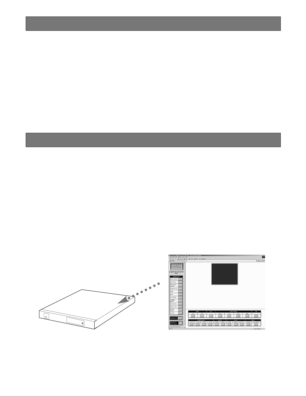
■ How to Read ADMINISTRATOR SETUP PAGE ..........79
■ MODE SETUP ............................................................81
■ NETWORK SETUP .....................................................83
■ VIDEO SEQ/ALARM SETUP .......................................84
■ SERIAL PORT SETUP ................................................86
■ USER SETUP .............................................................88
■ HOST SETUP .............................................................89
■ CLOCK SETUP ..........................................................90
■ CAMERA SETUP MENU ...........................................91
■ RECEIVING SETUP ....................................................92
■ DIRECTORY SETUP ...................................................93
■ ALARM DIALING TABLE SETUP ...............................94
■ OTHERS SETUP .........................................................95
MAINTENANCE.................................................................97
■ MAINTENANCE INDEX FILE SELECT .......................97
■ WJ-SX550B CAMERA MENU SETUP PAGE ..............98
■ WJ-FS616 MENU SETUP PAGE ................................99
■ WJ-FS616 CAMERA MENU SETUP PAGE ..............100
■ PS.Data MENU SETUP PAGE ..................................101
■ PS.Data CAMERA MENU SETUP PAGE ..................102
UTILITY SOFTWARE .......................................................103
ACCESS AUTHORIZATION ............................................104
■ Control of Access Authorization ..............................104
■ Access Level ...........................................................104
■ Registration ..............................................................105
EXTENSION FUNCTIONS ...............................................106
■ WJ-MP204 Data Multiplexer Control ........................106
■ WJ-FS616 Video Multiplexer Control .......................108
■ WJ-SX550B Matrix Switcher Control ........................111
■ WJ-DR200 AV Disk Recorder Control ......................114
■ WJ-FS309/316/409/416 Video Multiplexer Control ..116
■ WJ-HD100 Hard Disc Recorder Control ..................119
■ WJ-HD500 Digital Disk Recorder Control ................121
■ WJ-HD500 Digital Disk Recorder Control (PS.Data) 124
■ PS.Data Control
(WJ-FS416, WJ-MP204s & WJ-HD100) ...................127
CONTENTS UPLOAD .....................................................131
■ Uploading a File .......................................................131
■ Content Storage Memory .........................................131
CONTROL BY HTML DESCRIPTION ..............................132
■ Image Display ..........................................................132
■ Camera Operation ...................................................133
■ Substitute Character Strings in HTTP Server ...........137
TROUBLESHOOTING......................................................138
SPECIFICATIONS .......................................................... 142
STANDARD ACCESSORIES .......................................... 143
OPTIONAL ACCESSORIES ........................................... 143
APPENDIX ..................................................................... 144
■ Default Settings ........................................................144
■ Sensor Operation .....................................................146
■ About the Right of Control .......................................147
4
PREF ACE
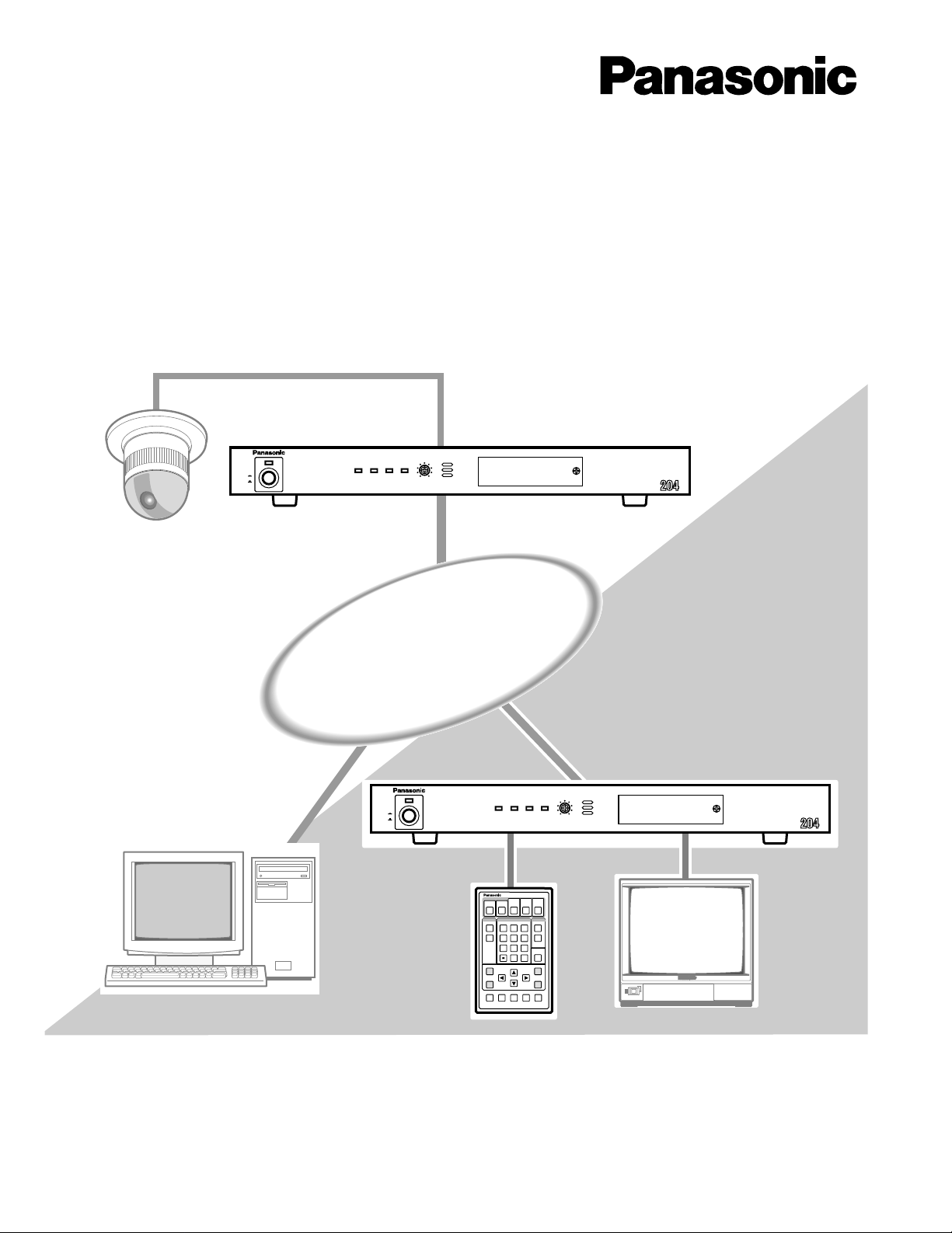
The Network Interface Unit WJ-NT204 is the key devices
for a remote surveillance system. The unit works as an
HTTP server and transmits high quality video on the H.261
or JPEG* standard basis, along with audio**. You can monitor remote places through a 10/100BASE-T Ethernet LAN.
Various systems can be built up ranging from a 1-1 site
system up to multiple site system.
A Remote site can install a maximum of 4 cameras with the
unit alone, or up to a number of cameras in combination
with peripheral devices such as Data Multiplex Units, etc.
The unit has serial and parallel interfaces to communicate
with those peripherals.
A Control site can be formed with a WJ-NT204 or a general
purpose PC. It receives video and audio to check them on
a video monitor or computer display while sending control
FEATURES
Audio/Video Transmission
• Up to 4 cameras can be connected when no peripherals installed at the Remote site.
• A Remote site supplies camera picture and audio** to
the Control site.
• Picture selection is made accordingly when the connected sensor operates or the Control site demands
the camera.
• Picture quality can be selected in accordance with network traffic and your requirement.
• Audio mute available (
Access to the Site
• TCP/IP is employed to permit use of existing Ethernet
LANs.
• Sensor (Alarm) activation triggers the Auto-dial function
to access to the Control site.
• One-touch dial and Quick dial are available with preset
addresses.
when H.261 mode is applied.)
commands to the Remote site devices for pan/tilt control,
camera selection and so forth.
Setup menus are pre-installed in the unit that make you
customize the settings most suitable to the system requirement. That is, for example, IP directory registration, dialing
sequences, camera switching sequences, etc. A Control
site PC can download the main page from the WJ-NT204.
Remote Controller WV-CU20 is an exclusive unit to operate
with the WJ-NT204 for dialing, camera selection, etc., in the
normal mode. It is also used for IP address registration,
sequential mode setup, alarm mode setup, etc., in the
setup mode.
*JPEG is applicable only when the Control site uses a browser on the PC.
**Audio transmission is available only when H.261 mode is applied.
Peripheral Interfaces
• Combination cameras
•
•PS
Data or other NORMAL devices such as PC
• Data communication/ RS-485 (PS
• 8 sensor inputs and 8 trigger outputs
• 8 parallel inputs and 8 parallel outputs
Setup menus
• View point setup
• Memories: Dialing number table/Alarm log/Communication log
• Maintenance
• Up/Download function enables the Control site to edit
the Remote site’s setup remotely.
• The built-in ringer beeps when receiving a call.
• Password protects your system from unauthorized
operation.
•
Data)/RS-232C
5
WJ-NT204
Copyrights
• MS-DOS is a registered trademark of Microsoft Corporation in the U.S.A. and other countries.
• Windows and Windows NT are trademarks of Microsoft Corporation in the U.S.A. and other countries.
• Netscape Navigator is a trademark of Netscape Communications Corporation.
• Adobe Acrobat Reader is a trademark of Adobe Systems Incorporated.
• Other company names and product names appearing in the manual are registered trademarks or trademarks of the companies concerned.
Homepage

PRECAUTIONS
• Refer all work related to the installation of this product to qualified service personnel or system
installers.
• Do not attempt to disassemble the appliance.
To prevent electric shock, do not remove screws or
covers.
There are no user-serviceable parts inside. Contact
qualified service personnel for maintenance.
• Handle the appliance with care.
Do not strike or shake, as this may damage the appliance.
• Do not expose the appliance to water or moisture,
nor try to operate it in wet areas.
Do take immediate action if the appliance becomes
wet. Turn the power off and refer servicing to qualified
service personnel. Moisture may damage the appliance and also cause electric shock.
• Do not use strong or abrasive detergents when
cleaning the appliance body.
Use a dry cloth to clean the appliance when it is dirty.
When the dirt is hard to remove, use a mild detergent
and wipe gently.
• Do not operate the appliance beyond its specified
temperature, humidity or power source ratings.
Do not use the appliance in an extreme environment
where high temperature or high humidity exists.
Use the appliance at temperatures within −10°C +50°C (14°F - 122°F) and a humidity below 90 %.
The input power source for this appliance is 120 V AC
60 Hz.
6
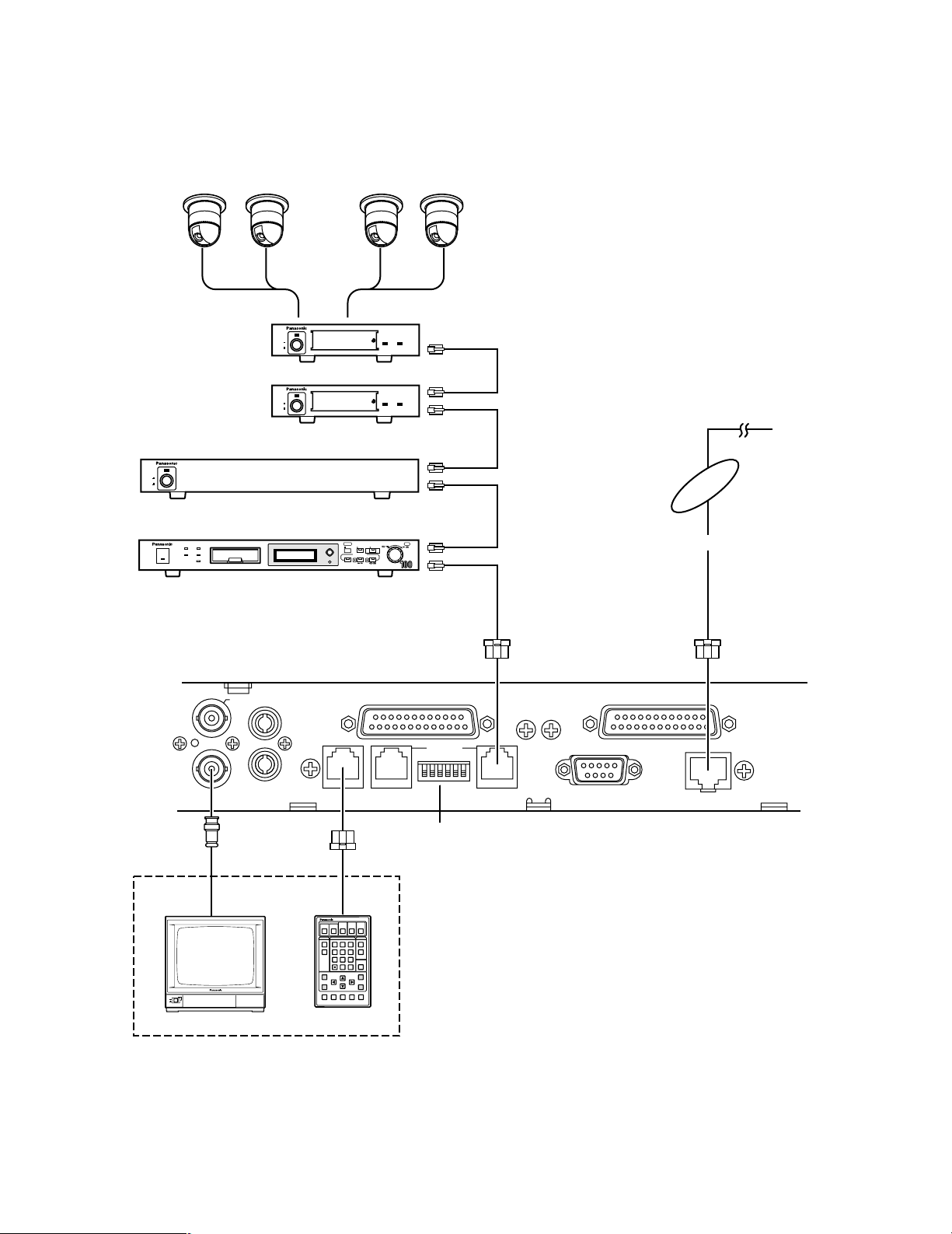
SYSTEM CONFIGURATION
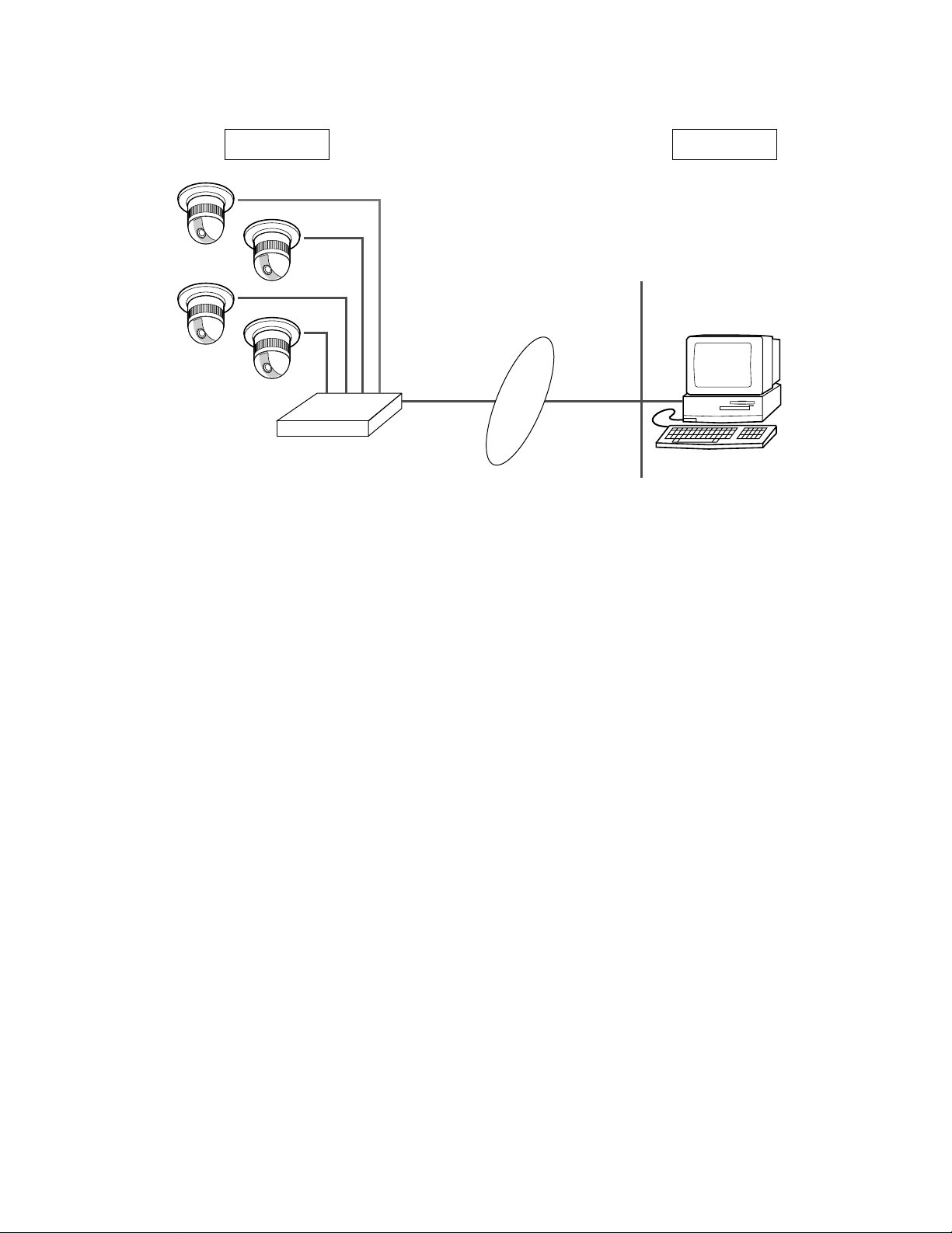
WJ-NT204
Network Interface Unit
(Transmitter)
WJ-NT204
Network Interface Unit
(Receiver)
Ethernet LAN
ON
OFF
POWER
Video Monitor
ESC
MENU
AF NEAR FARTELE WIDE
Remote Controller WV-CU20
123
456
7809
12345
#
STEP 1
DIAL
PRESET SET
QUICK
STEP 2 STEP 3
CALL
REDIAL
DELETE
ENTER
AUDIO MUTE
ALM ACKVIDEOSWITCH
ONE TOUCH DIAL
AUTO/MANU
SITE
Combination Cameras (4)
Remote Site Control Site
WV-CU20
Exclusive Remote Controller
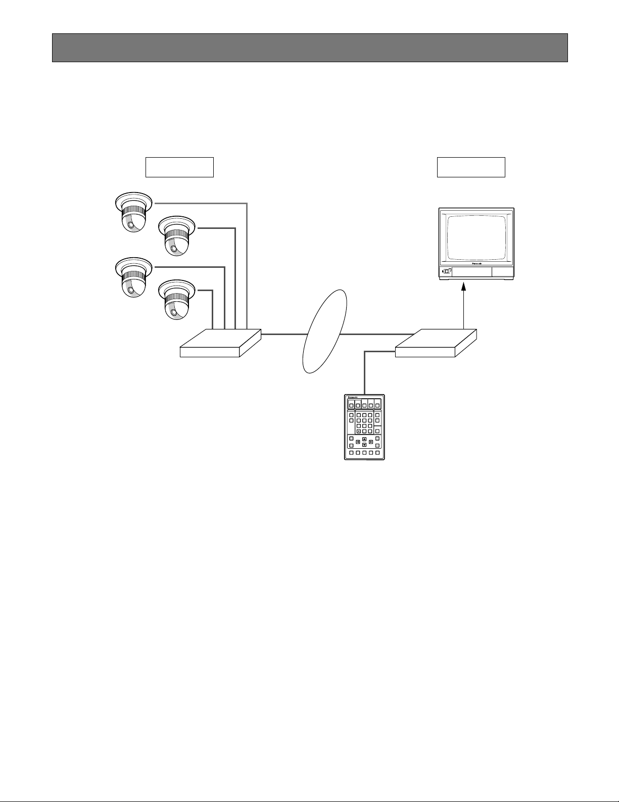
There are some system forms depending on the number of the sites, and the network routings.
■ Basic Connection with WJ-NT204 Receiver
In the basic connection, the Control site can connect to the Remote site all the time as necessary.
7
■ Basic Connection with PC Browser
WJ-NT204
Network Interface Unit
(Transmitter)
Combination Cameras (4)
Remote Site Control Site
LAN
PC (Browser)
Ethernet LAN
8
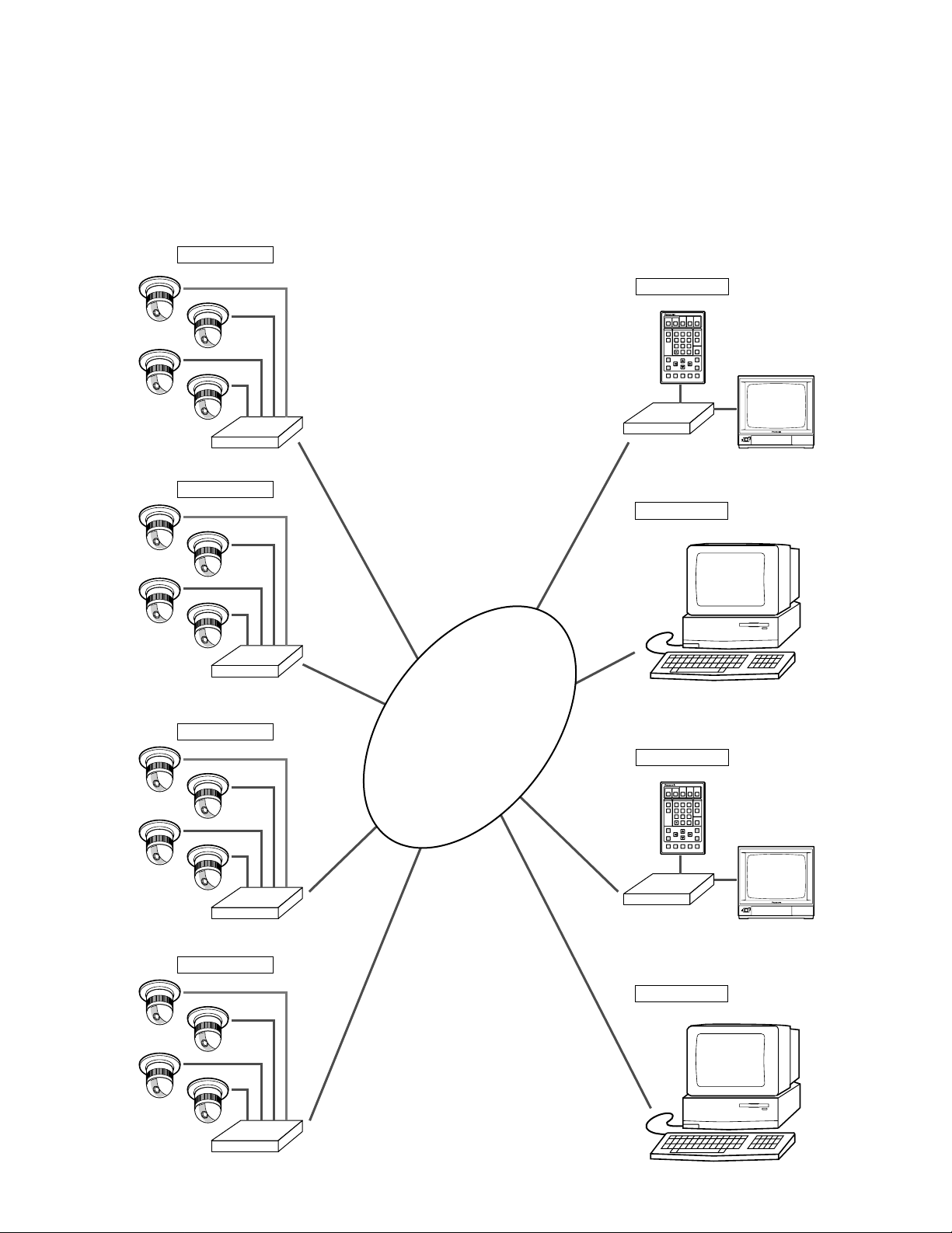
■ Multi-site Connection
ON
OFF
POWER
ESC
MENU
AF NEAR FARTELE WIDE
Remote Controller WV-CU20
123
456
7809
12345
#
STEP 1
DIAL
PRESET SET
QUICK
STEP 2 STEP 3
CALL
REDIAL
DELETE
ENTER
AUDIO MUTE
ALM ACKVIDEOSWITCH
ONE TOUCH DIAL
AUTO/MANU
SITE
WJ-NT204
Remote Site 1
Control Site 1
Remote Site 2
WJ-NT204
Remote Site 3
WJ-NT204
Remote Site 4
WJ-NT204
WJ-NT204
Control Site 2
ON
OFF
POWER
ESC
MENU
AF NEAR FARTELE WIDE
Remote Controller WV-CU20
123
456
7809
12345
#
STEP 1
DIAL
PRESET SET
QUICK
STEP 2 STEP 3
CALL
REDIAL
DELETE
ENTER
AUDIO MUTE
ALM ACKVIDEOSWITCH
ONE TOUCH DIAL
AUTO/MANU
SITE
Control Site 3
WJ-NT204
Control Site 4
Ethernet
LAN
The Multi-site connection enables you to monitor the same image at a maximum of 4 Control sites. A Remote site can transmit
images up to 4 Control sites.
Camera selection and camera control is made by only one Control site at a time. This results in a sudden change of monitoring
image in the site that did not operate the camera.
Another Remote site may call the Control site that is in communication with the currently connected Remote site. You can
select operations from options such as ACCEPT or REJECT at the Control site. See page 37 for detailed operations. Access
from the Control site is available as far as the Remote site is connected with less than 4 Control sites. Refer to Appendix for
the right of the control.
9
or
TI Router etc.
LAN
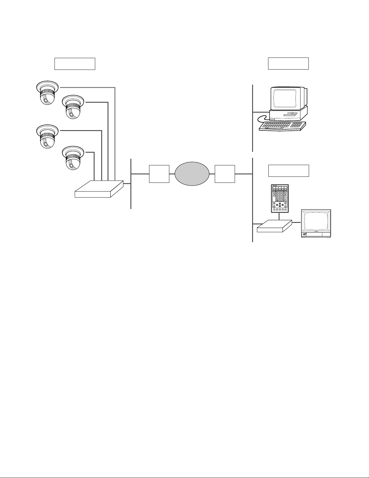
Control Site 1
Control Site 2
LAN
ADSL
Modem
or
TI Router etc.
ADSL
Modem
Internet
ON
OFF
POWER
ESC
MENU
AF NEAR FARTELE WIDE
Remote Controller WV-CU20
123
456
7809
12345
#
STEP 1
DIAL
PRESET SET
QUICK
STEP 2 STEP 3
CALL
REDIAL
DELETE
ENTER
AUDIO MUTE
ALM ACKVIDEOSWITCH
ONE TOUCH DIAL
AUTO/MANU
SITE
WJ-NT204
PC (Browser)
WJ-NT204
Network Interface Unit
(Transmitter)
Global IP
Combination Cameras (4)
Remote Site
■ Access from an Internet
The PC accesses to the Remote site via Internet.
10
MAJOR OPERATING CONTROLS AND THEIR FUNCTIONS
RS-232C
HOST PORT
q
yuio
wert
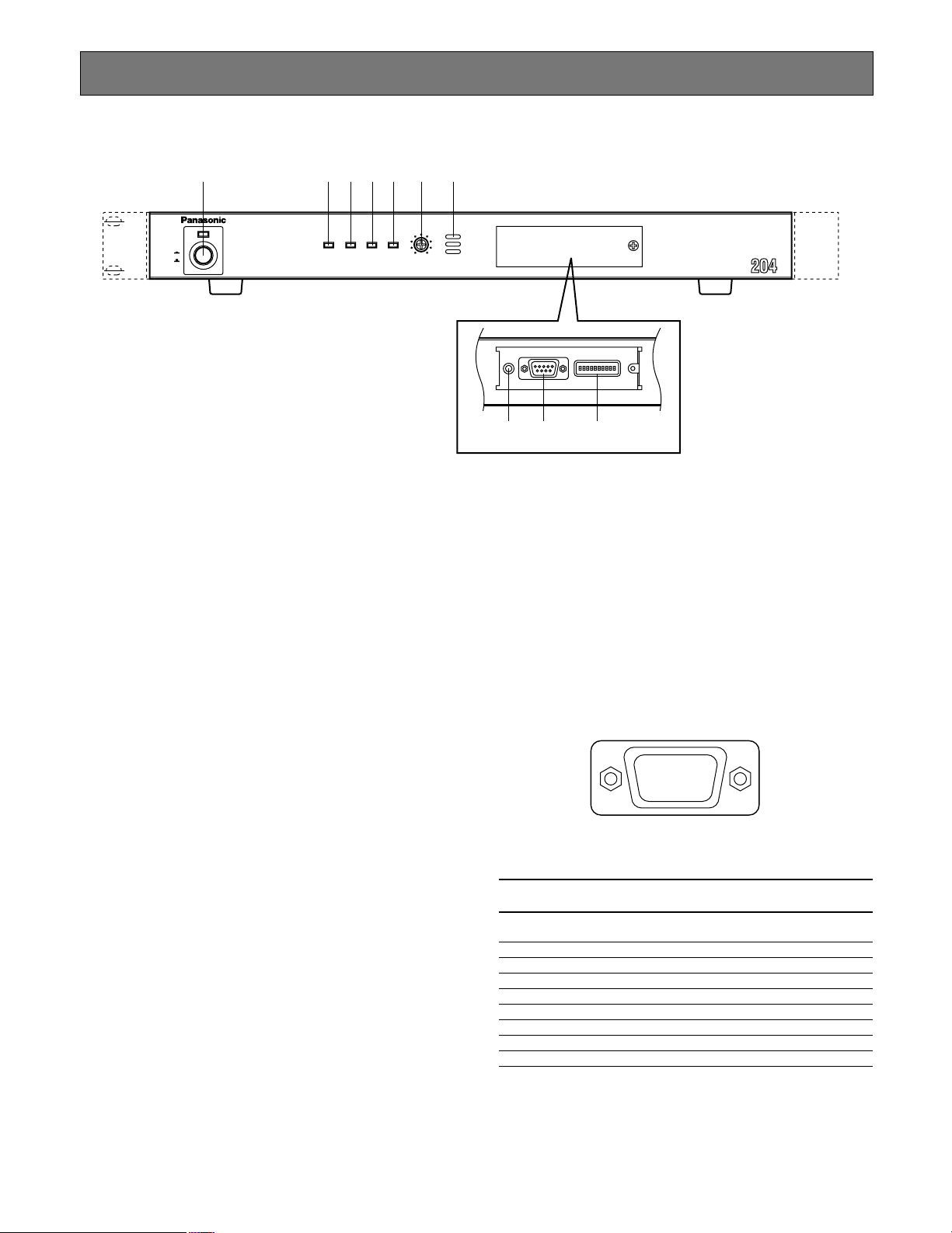
■ Front View
q w e r t y u
LINK/
100
10BASE-T
POWER
ON
OFF
BASE-TX CONNECT ACT
q Power Switch & Power Indicator [POWER]
Press this switch to turn on or off the power of the unit.
The indicator lights while the power is turned on.
w [LINK/10BASE-T] indicator
Lights when communication is established through
lines (LINK) or a 10BASE-T LAN.
e [100BASE-TX] indicator
Lights when communication is established through a
100BASE-T LAN, along with the LINK/10BASE-T indicator.
RING.VOL
LOW HIGH
Network Interface Unit WJ-NT
RS-232CRESET
HOST PORT
MODE
i o !0
o RS-232C Host Port [RS-232C HOST PORT]
The unit communicates with the host computer through
this D-Sub 9-pin connector. Setting the MODE DIP
switch #9 specifies the mode and usable port from
among RS-485 (Rear Panel) and RS-232C (Front
Panel). Available controls are as follows.
• Communication control such as calling and disconnection
• Up/Download for software
• Download for communication log and alarm log
r [CONNECT] indicator
Lights when signaling the data only in H.261 mode.
t [ACT] indicator
Blinks when receiving and sending IP packets.
y Ringer Volume Control [RING. VOL]
Turn this control to adjust the sound level that beeps
when receiving a call.
u Ringer Buzzer
Beeps when receiving a call only in H.261 mode.
i Reset Button [RESET]
Pressing this button shuts down the current operation
and restarts the system.
RS-232C Host Port
Signal Function Direction as seen from
No.
name WJ-NT204
1C D
2 R D Receiving data Input
3 S D Sensing data Output
4 E R Data connection ready Output
5 S G Signal Ground –
6 D R Data set ready Input
7 R S Request send Output
8 C S Send enabled Input
9 N. C. (Not used)
Receiver carrier Input
detection
11

123 45678910
OFF
ON
!0 Mode DIP Switch [MODE]
The default setting is marked with *.
After changing the DIP switch, make sure to turn OFF
the power switch once and then turn it ON, or press the
RESET button to take in the new settings to the unit.
Bit # OFF ON Function/Note
1 Normal Operation * Initialize(1)
2 Normal Operation * Initialize(2)
3*
4 See below *
5 See below *
6 Normal Operation* Initialize(3)
7*
Setup Menu
8
Enabled *
9 RS-485 Rear RS-232C Front*
10 *
Menu Disabled
Maintenance
HTML file
Not Used
Applicable Line
Applicable Line
Network
Configuration
Not Used
Setup Menus
Host Port
Selection
Not Used
Initialize(1) will reset all settings including IP address back
to the factory default.
Initialize(2) will reset the HTML contents files back to the
factory default settings.
Initialize(3) will reset the IP address, subnet mask and
default gateway back to the factory default settings.
12
Applicable Line
Bit #4
OFF ON
OFF AUTO * 10BASE-T
Bit #5
ON 100BASE-TX AUTO
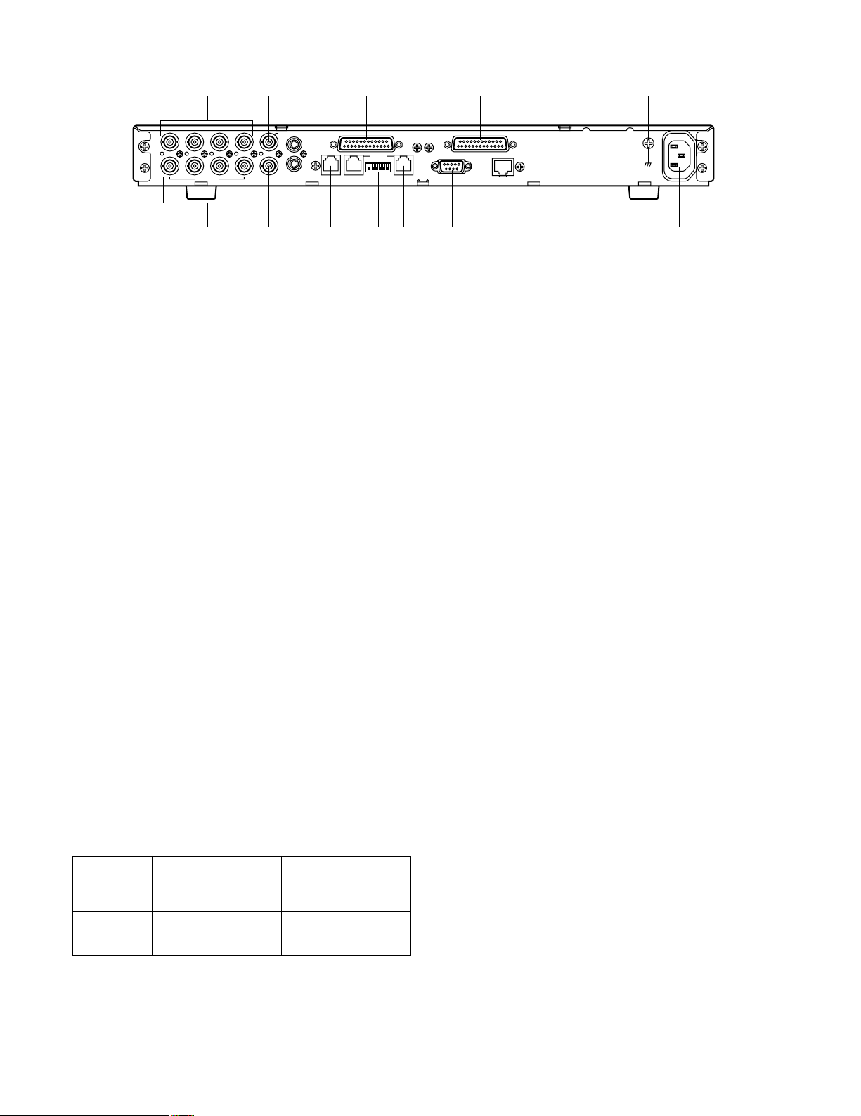
■ Rear View
I N
4433221
OUT
@1
VIDEO
@4
@2
@3 @7 @8 #5
AUX
I N
OUT
1
MON/SPOT AUDIO
@6 @9 #0 #2 #3 #4 #6#1
@5
SENSOR IN/TRIGGER OUT PARALLEL PORT
I N
OUT
REMOTE SETUPHOST PORT DATA PORT DATA PORT
@1 Video Input [VIDEO IN 1, 2, 3, 4]
Connect a maximum of four Panasonic’s Combination
Cameras in the Remote site where the unit is set to
Transmitter mode. These BNC receive composite video
signals from the cameras while the control commands
(e.g., pan/tilt, focus, etc.) pass through these terminals.
This will be used only for the Remote site.
@2 Auxiliary Video Input [AUX IN]
Connect an ordinary camera rather than a Combination
Camera, or an image reproduction device such as
Digital Disk Recorder, VCR and so forth with this BNC.
This BNC is used at the Remote site where the unit is
set to Transmitter mode. This will be used only for the
Remote site. The image supplied to the AUX IN will not
be output to the MONI/SPOT terminal on the Remote
site, however it is transmitted to the Control site.
@3 Audio Input [AUDIO IN]
Accepts audio signal from the outboard device. Audio
is transmitted to the other site. Audio transmission can
be interrupted if you press the MUTE button on the
Remote Controller. Press it again to resume the transmission.
@4 Video Output [VIDEO OUT 1, 2, 3, 4]
Video In signal 1-4 are looped through to these BNC in
the Remote site. If connected, make certain to terminate at the connected device with a 75 Ω resister
because the automatic termination will be released in
the unit. This will be used only for the Remote site.
@5 Monitor/Spot Output [MON/SPOT]
This BNC little changes in function depending on the
unit setup to a Receiver or a Transmitter.
Setup Available Video On-Screen Setup
The designated camera
picture by the Receiver
Transmitted video supplied by the Transmitter
AvailableTransmitter
AvailableReceiver
RS–485
SIGNAL GND
RS–232C
10BASE-T/100BASE-TX
AC IN
@6 Audio Output [AUDIO OUT]
Outputs audio signal supplied from the other site.
Audio transmission is enabled or disabled depending
on the setting conditions at the other site.
@7 Sensor Input/Trigger Output [SENSOR IN/TRIGGER
OUT]
A D-Sub 25-pin connector has 8 inputs and 8 outputs
for sensor-related wiring. This is used only for the
Remote site.
A SENSOR IN terminal receives the signal from the
connected sensor that is installed in conjunction with
the camera position or its aiming position. A TRIGGER
OUT terminal relays the sensor input information to the
connected device such as Hard Disk Recorder, Video
Multiplexer, etc. These devices will enter alarm recording mode accordingly. The Network Interface unit, following the setup, will enter Alarm Dialing or Camera
Switching when the sensor input comes in. The TRIGGER OUT terminal also supplies the VIDEO SWITCH
selection information. See page 24-26 for connection
and specifications.
@8 Parallel Port [PARALLEL PORT]
A D-Sub 25-pin connector has parallel inputs and outputs for auxiliary control purposes with optionally
installed switches and other devices. The following 3
functions perform on the unit basis while the others perform between the Control and Remote site.
The internal clock is adjusted to the hour (xx:00:00)
when an externally connected switch is turned on, as
far as the clock deviates within 3 minutes before or
after the hour.
Current communication will be forcibly disconnected
when an externally connected switch is turned on.
The In-Communication Status Out will be active while
the unit on the site is in communication, not the unit on
the other site.
Parallel inputs and outputs are used between the
Control site and Remote site.
Parallel input information is reflected to parallel output
terminals on the other site, from a Control site to
Remote site or vice versa. For example, an electric
lamp can be turned on to illuminate the aiming zone of
the camera on the Remote site when the switch connected to a parallel input is pressed on the Control site.
See page 27 and 28 for connection and specifications.
13
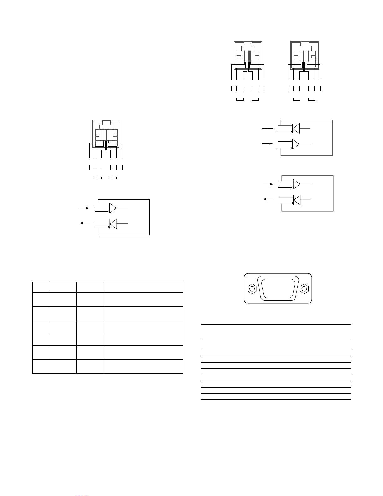
@9 Controller Port [REMOTE]
HOST PORT
GND
BABA
GND
123456
Receive
RS-485
Host port
Transmit
5
4
TA
TB
Transmit
3
2
RA
RB
Receive
WJ-NT204
Straight
For PC
DATA PORT DATA PORT
GND
BABA
GND
123456
GND
BABA
GND
123456
Transmit Receive TransmitReceive
RS-485 Data port
Crossover
(Transmitter)
Straight
(Receiver)
5
4
TA
TB
Transmit
3
2
RA
RB
Receive
WJ-NT204
Straight (Receiver)
For
System Controller
ex.) WV -CU360
5
4
RA
RB
Receive
3
2
TA
TB
Transmit
WJ-NT204
Crossover (Transmitter)
For
Matrix
Switcher
RS-232C
DATA PORT
q
yuio
wert
Connect with a Remote Controller WV-CU20 that only
operates the unit. Connection cable is a 6-conductor
modular type included in the Controller. (RJ-11)
#0 RS-485 Host Port [RS-485 HOST PORT]
Use this when connecting with another WJ-NT204 unit
to operate them from a single controller such as a PC
through the RS-485 daisy chain. Make certain to set the
DIP switch #9 on the front panel to OFF when using this
port. (RJ-11)
#1 Setup DIP Switch [SETUP]
A 6-bit DIP switch is provided with the following function. The default position is marked with *. See INSTALLATIONS on how to set these switches.
Bit # OFF
Open*
#1
Open*
#2
Receiver*
#3
(Straight)
RS-485*
#4
Open*
#5
Open*
#6
#2 RS-485 Data Port [RS-485 DATA PORT]
Use this when connecting with other PS
(Panasonic Security) devices such as WJ-MP204 Data
Multiplex Unit, WJ-FS409 Video Multiplexer and so forth
to operate them from a Remote Controller through the
RS-485 chain.
The DIP switch #4 on the rear panel must be set to OFF
when using as an RS-485, or to ON as an RS-232C.
The DIP switch #3 on the rear panel changes terminal
wiring either Straight or Crossover as shown below.
(RJ-11)
This switch is set to OFF for a Receiver, and ON for a
Transmitter when CCTV devices are connected.
14
ON
Terminate
Terminate
Transmitter
(
Cross)
RS-232C
Terminate
Terminate
Function/Note
Termination on Transparent
Receiving side
Termination on Transparent
Transmission side
RS-485 DATA PORT wiring
exchange
DATA PORT selection
Termination on Host Receiving
side
Termination on Host Transmission
side
•
Data
#3 RS-232C Data Port [RS-232C DATA PORT]
Use this when communicating with other RS-232
devices through D-Sub 9-pin connector. The pin function is basically the same as the RS-232C HOST port
on the front panel.
RS-232C Data Port
Signal Function Direction as seen from
No.
name WJ-NT204
1C D
2 R D Receiving data Input
3 S D Sensing data Output
4 E R Data connection ready Output
5 S G Signal Ground –
6 D R Data set ready Input
7 R S Request send Output
8 C S Send enabled Input
9 N. C. (Not used)
Receiver carrier Input
detection
#4 Ethernet Port [10BASE-T/100BASE-TX]
Connect the 10/100BASE-T terminal to an Ethernet with
a 10BASE-T or 100BASE-TX cable.
#5 Signal Ground [SIGNAL GND]
#6 AC Inlet [AC IN]
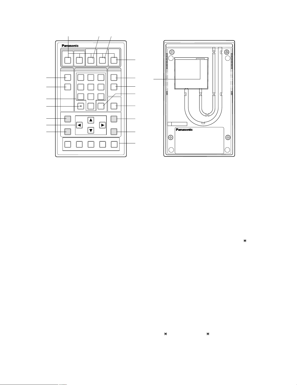
■ WV-CU20 Remote Controller (Option)
$5
$6
%1
%2
$1
ONE TOUCH DIAL
12345
STEP 1
DIAL
QUICK
PRESET SET
ESC
Remote Controller WV-CU20
SITE
STEP 2 STEP 3
123
456
7809
$2
AUTO/MANU
#
$3
ALM ACKVIDEOSWITCH
CALL
REDIAL
DELETE
AUDIO MUTE
%3
%4
MENU
ENTER
%5
AF NEAR FARTELE WIDE
$1 One-touch Dial Buttons [ONE TOUCH DIAL, 1 - 5]
These buttons are used to call the destinations preset
to the buttons. Press the DIAL, then any of them.
$2 Switch Site Button[SWITCH SITE, 3]
This button is used to switch the site from the currently
communicating to another one when communicating
with more than one site. Highlight a site on the receiver
monitor with the direction button, then press this button.
$3 Video Scanning Mode Button
[VIDEO AUTO/MANU, 4]
This button is used on the receiver to toggle the scanning mode automatically and manually.
$4 Alarm Acknowledge Button [ALM ACK, 5]
This button is used on the receiver to acknowledge activated alarms.
$5 Dial Button [DIAL]
This button is used to open the DIRECT DIAL window
where you can enter an IP address prior to start dialing.
After pressing this button, specify an IP address from
the registered directory or on the DIRECT DIAL window.
To terminate the call, hold down this button for 2 seconds.
$6 Quick Dial Button [QUICK]
This button is used to select Quick (Short) Dial numbers
stored in the menu.
$77 Call Button [CALL]
This button is used to call the IP address that may be
picked up from the registered directory or may be
$4
$7
$8
$9
%0
%6
%7
%8
%9
SER
NO.
entered in the DIRECT DIAL window. After specifying
the IP address, then press this button.
$88 Redial Button [REDIAL]
This button is used to redial the last called destination if
the power of the unit has been tuned on after the call.
The last called number is reset when the power of the
WJ-NT204 is turned off.
$9 # SET Button [#, SET]
For camera selection, enter a camera number 1 through
5, then press this button.
For preset position selection, press [
[number], and this button.
This is also used to confirm the selected parameter in
the setup menus, or to reset all parameters in the camera setup.
%0 Delete Button [DELETE]
This button is used to correct any numeric or alphabetic
input in the menu.
Pressing this button will delete the character followed
immediately by the cursor.
%1 Numeric Buttons [0 - 9]
These buttons are used to enter numeric characters for
phone numbers, passwords, and camera selection.
%2 PRESET Button [
, PRESET
This button is used to specify a camera preset position.
Press this button, [number], and then [#, SET] button to
recall the camera preset position.
In the camera setup menu, pressing this button will
reset all parameters, or change the menu to SPECIAL.
]
, PRESET
],
15

%3 Escape Button [ESC]
This button is used to escape and execute the currently
highlighted setting on the setup menu. The monitor
screen will then return to the previous setup menu.
%4 Direction Buttons [t ▲ s ▼]
These buttons are used to control the pan/tilt head in
the normal operations when the Combination Cameras
are connected to the transmitter.
%5 Menu Button [MENU]
This button is used to open or close the setup menu on
the monitor screen.
%6 Audio Mute Button [AUDIO MUTE]
This button is used to mute the outgoing sound from the
local site.
Pressing it again will restore the sound.
%7 Enter Button [ENTER]
This button is used to confirm the selection in the setup
menu or to open the submenu where more details are
set.
%8 Camera Control Buttons
These buttons are used to operate the zoom/focus lenses capable of remote control if they are mounted on the
cameras.
TELE/WIDE: Zooms in or out the image.
NEAR/FAR: Adjusts the focus.
AF: Focusing is automated and adjusted to the best
position thanks to the built-in circuitry.
%9 Connection Port
This port is used to connect with the REMOTE port on
the rear of the WJ-NT204 Network Interface Unit.
To connect to the unit, use a 6-conductor modular
cable supplied as an accessory with the controller.
16

INSTALLA TIONS
• The following installations should be made by qualified service personnel or system installers and should conform
to all local codes.
• For permanetly connected unit, a readily accessible disconnection device shall be incorporated in the fixed wiring:
An ALL-POLE MAINS SWITCH with a contact separation of at least 3 mm in each pole in the electrical installation
of the building
An easily accessible wall-outlet to unplug the power cord of the unit
An easily accessible AC inlet to unplug the power cord of the unit
[To working personnel]
Prior to starting work, turn off the power supply and pull out the power plug out of the wall outlet.
Inform the user of the fact that more than 48 hours of charging is required for initial usage after the completion of connections.
Operation of the clock used in this unit is sustained by backup operation of the built-in battery. When this unit is initially used,
continuous charging is needed for more than 48 hours so that the backup battery can be charged up. In the following cases,
the clock may become out of order:
• Lack of charging time
• A service interruption continued for a long time
• The POWER switch has been set at OFF for a long time, or the power plug has been left disconnected from the wall outlet.
If the clock becomes out of order, set the clock again.
The contents of the abbreviated directory and various setting data are stored in nonvolatile memory, and they cannot be lost
even if there is a service interruption.
17
SWITCH
PROTECTOR
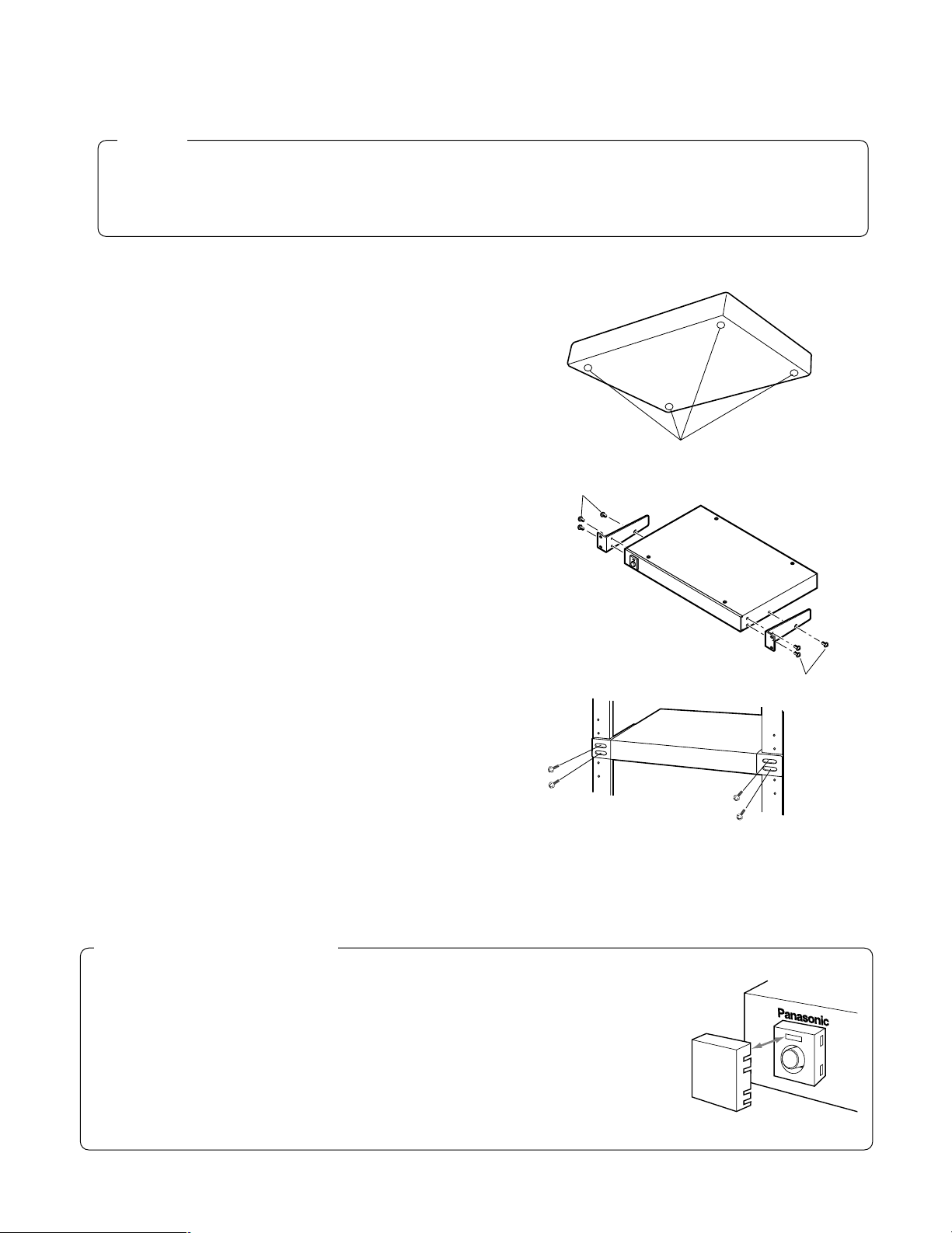
■ Mounting in the Rack
Caution
• Do not block the ventilation opening or slots on the cover which prevent the appliance from overheating.
Always keep the temperature on the rack within 45°C (113°F).
• Secure the rear of the appliance to the rack using the additional mounting brackets (procured locally) if the rack is
subject to vibration.
1. Loosen the four screws to remove the four rubber feet
from the bottom of the Network Interface Unit.
2. Place the rack mounting brackets on both sides of the
Network Interface Unit and tighten them with the six
supplied screws.
M3 (supplied)
Remove the rubber feet.
3. Install the Network Interface Unit with the rack mounting brackets in the rack using four screws (not included).
Accessory Switch Protector
If this switch protector is used, then it is possible to avoid the Network Interface Unit being
turned off by careless pressing of the unit POWER switch.
In case of gang power ON/OFF operation incorporated in the rack, the unit POWER switch
must always be moved to the ON position and the accessory switch protector should be
mounted.
M3 (supplied)
18
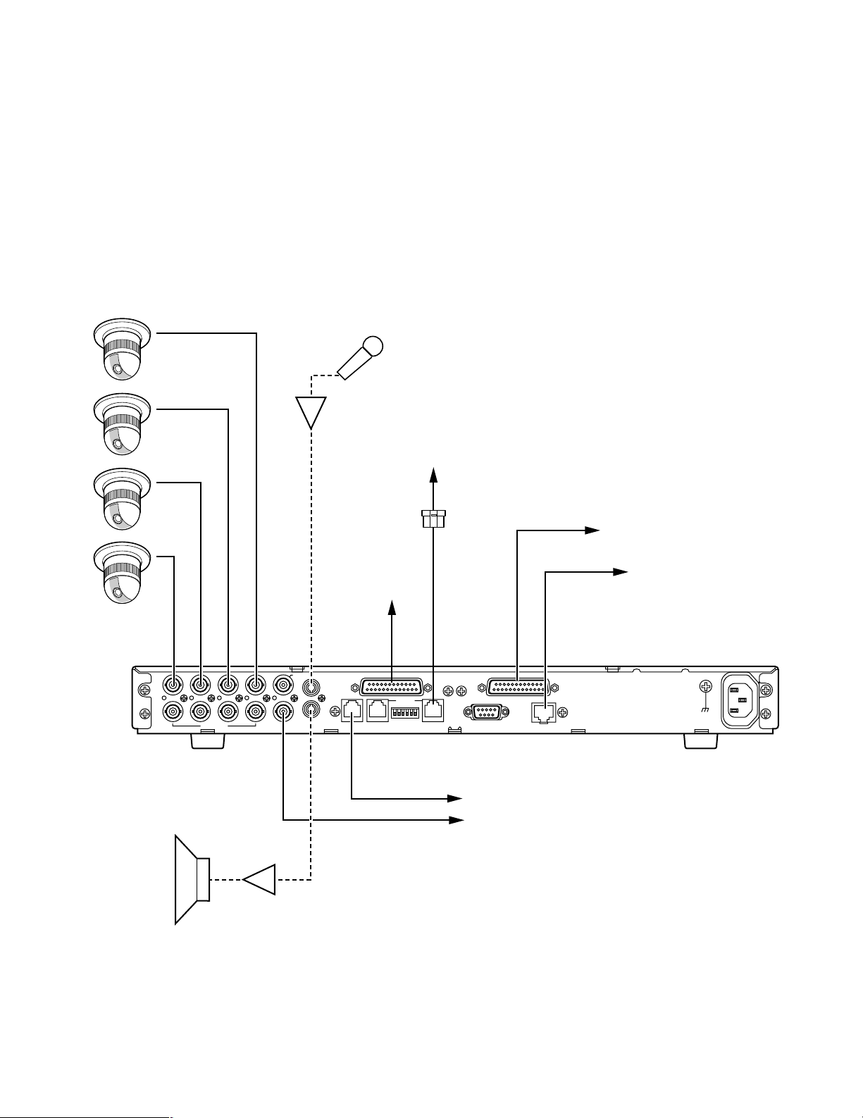
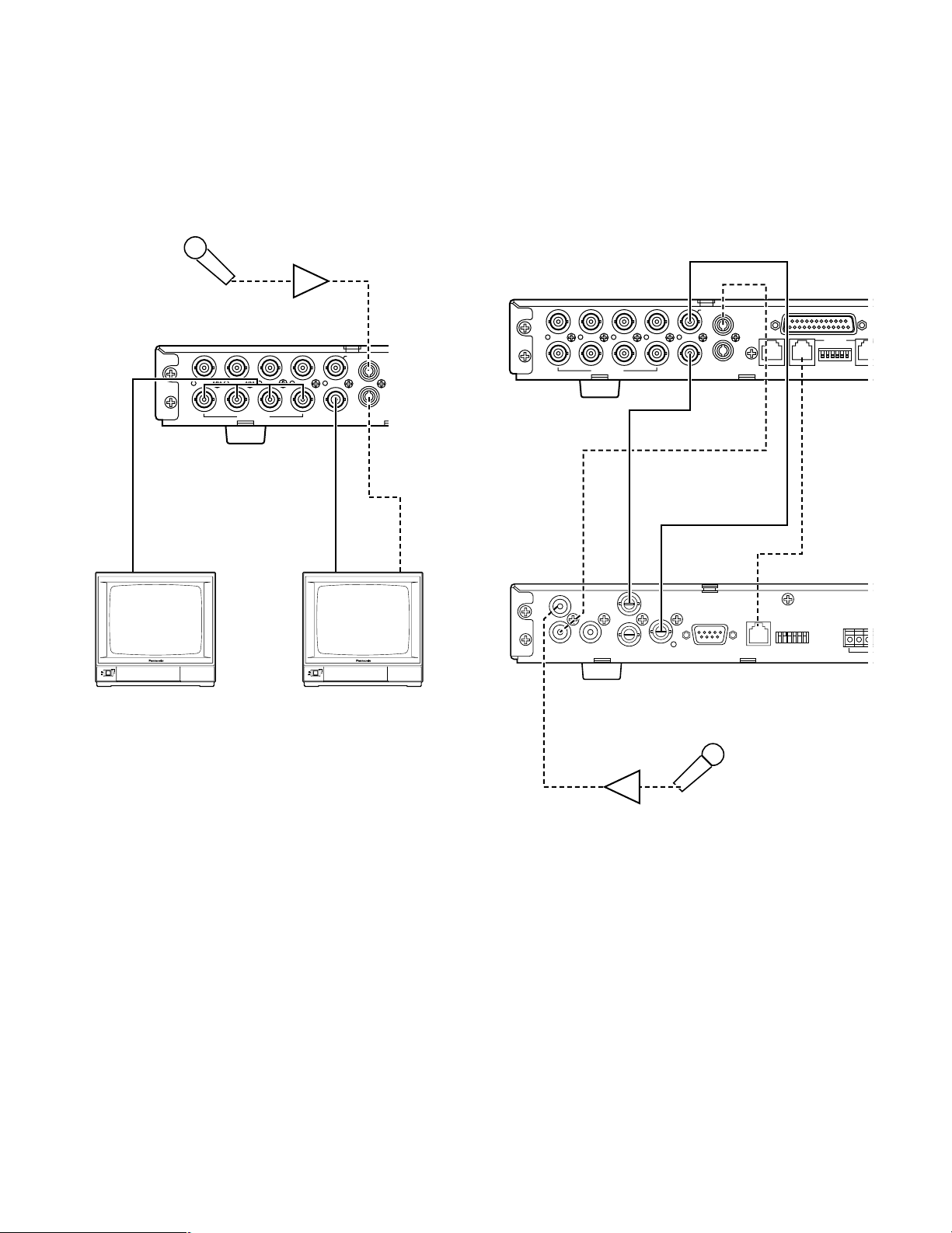
■ On the Remote Site (Transmitter)
SIGNAL GND
AC IN
RS–232C
RS–485
4433221
1
AUX
I N
REMOTE SETUPHOST PORT DATA PORT DATA PORT
10BASE-T/100BASE-TX
OUT
OUT
OUT
I N
I N
SENSOR IN/TRIGGER OUT PARALLEL PORT
VIDEO
MON/SPOT AUDIO
Combination Camera
or Ordinary Camera
Microphone
Amplifier
VIDEO IN
1234
AUDIO IN
See page 29.
See page 24 - 26.
To CCTV devices
See page 19 - 23, 29.
See page 29.
See page 27, 28.
Network Interface Unit
(Transmitter)
Amplifier
Speaker
Procure cables and connectors locally, when they are not supplied as standard accessories. For details on connections, refer
to the manual provided with the device.
● Audio/Video Connection on the Remote Site
1. Camera Connections
Connect the VIDEO IN terminals 1 through 4 to a maximum of 4 Combination cameras or ordinary cameras with coaxial
cables and BNC connectors. When an audio input is available, connect it to the AUDIO IN/OUT terminal using an audio
cable with the RCA plug.
19
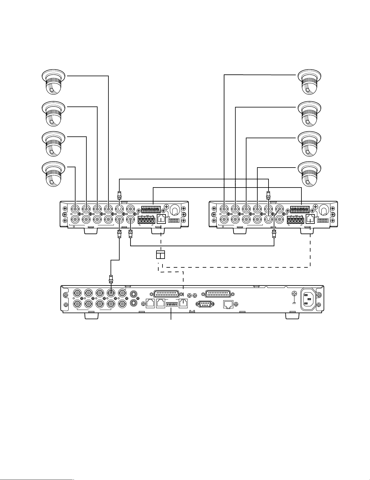
2. Data Multiplex Unit Connections
SD RD
IN IN
CAMERA RS485
ABABG
VS/VDSPOT DATA
ALARM / REMOTE
MODE
SIGNAL GND
4321
OUT OUTINOUT
4321
TR
IN IN
CAMERA RS485
ABABG
VS/VDSPOT DATA
ALARM / REMOTE
MODE
SIGNAL GND
4321
OUT OUTINOUT
4321
SPOT IN SPOT OUT
VS/VD OUT
SPOT OUT
VIDEO IN
VS/VD IN
SIGNAL GND
AC IN
RS–232C
RS–485
4433221
1
AUX
I N
REMOTE SETUPHOST PORT DATA PORT DATA PORT
10BASE-T/100BASE-TX
OUT
OUT
OUT
I N
I N
SENSOR IN/TRIGGER OUT PARALLEL PORT
VIDEO
MON/SPOT AUDIO
Network Interface Unit
Data Mutiplex UnitData Mutiplex Unit
1234 1234
Combination Cameras
Set #3 to ON
RS-485 Cable
(Transmitter)
SPOT SW IN
SPOT SW OUT
When the site contains Data Multiplex Units, connect these units with cameras as shown. Connect among the units, from
SPOT IN to SPOT OUT, from VS/VD OUT to VS/VD IN, from SPOT SW IN to SPOT SW OUT. Also connections from SPOT
OUT to VIDEO IN on the Network Interface Unit, and RS-485.connections are needed.
20
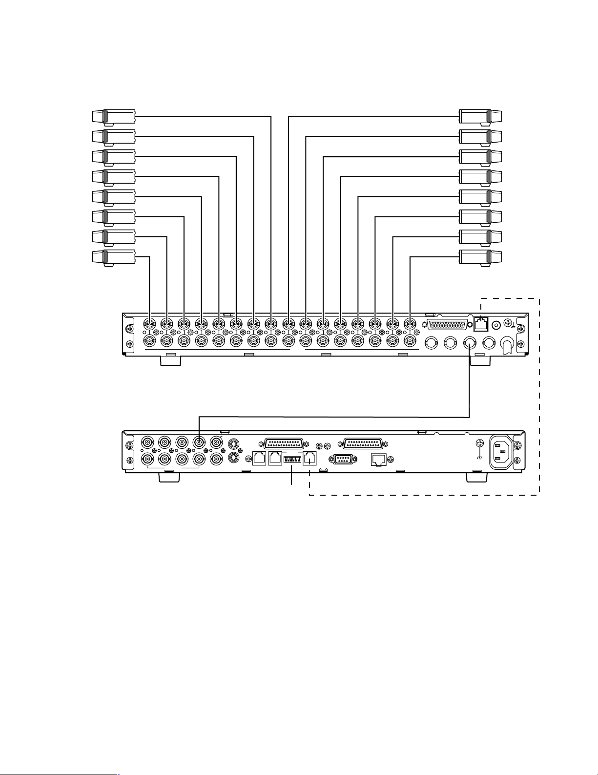
3. Video Multiplexer Connections
SIGNAL
GND
ALARM/REMOTE
OUT
IN
VIDEO
16 15 14 13 12 11 10 9 8
16 15 14 13 12 11 10 9 8
7654 21
76543321
PLAY IN
REC OUT
SPOT OUT
DATA
CAMERA
SW IN
MULTI
SCREEN
OUT
VIDEO IN
Cameras
VIDEO OUTPUT
SIGNAL GND
AC IN
RS–232C
RS–485
4433221
1
AUX
I N
REMOTE SETUPHOST PORT DATA PORT DATA PORT
10BASE-T/100BASE-TX
OUT
OUT
OUT
I N
I N
SENSOR IN/TRIGGER OUT PARALLEL PORT
VIDEO
MON/SPOT AUDIO
16 15 14 13 12 11 10 9 8 7 6 5 4 3 2 1
12
MULTI
SCREEN OUT
Network Interface Unit
Set #3 to ON
RS-485 Cable
(Transmitter)
Video Multiplexer WJ-FS416
or similar model
When the site contains the Video Multiplexer, connect it with cameras as shown. More connections are needed from
MULTI SCREEN OUT to VIDEO IN 1, and RS-485 connections.
21
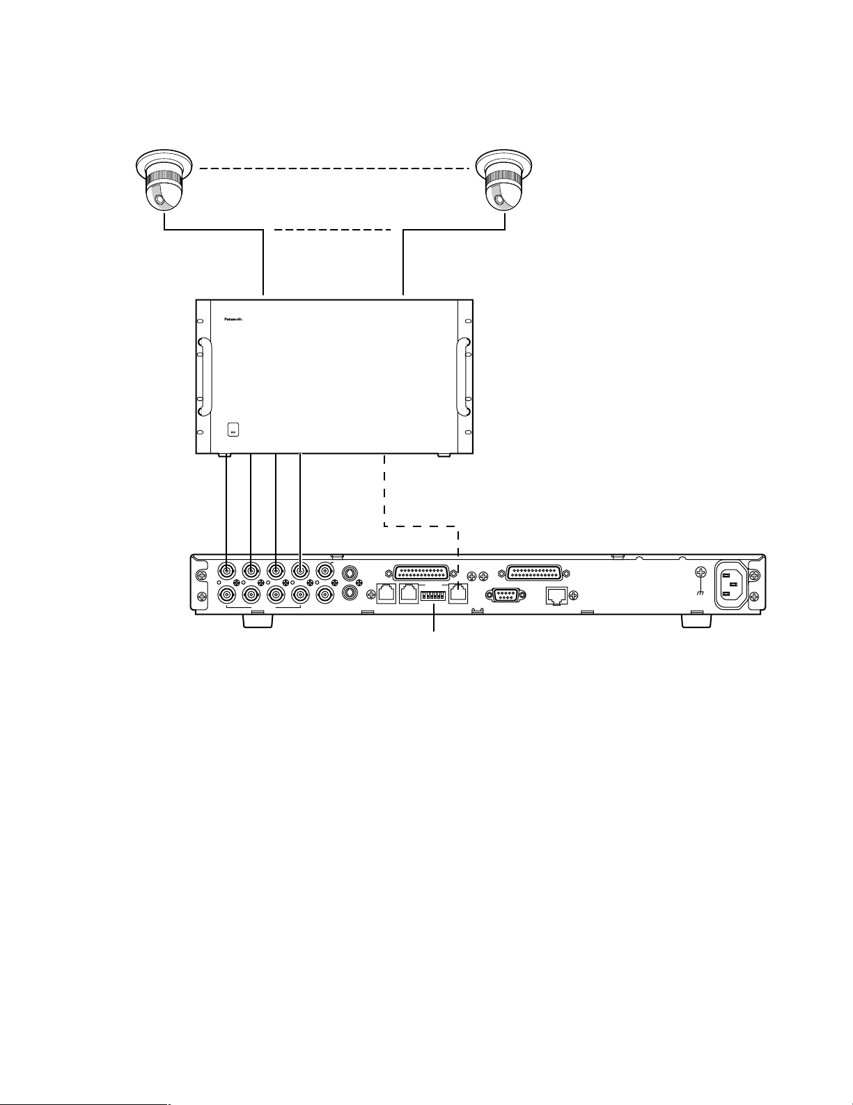
4. Matrix Switcher Connections
550
When the site contains a System 550 Matrix Switcher, connect it with cameras as shown. Connect the VIDEO OUT on the
MATRIX SWITCHER WJ-SX550 A/B with the VIDEO IN 1-4 on the WJ-NT204. Refer to the manual included in the WJ-SX550
A/B.
Combination Cameras
OPERATE
I N
4433221
OUT
VIDEO
234
MONITOR
OUT
VIDEO IN
1
AUX
I N
OUT
1
MON/SPOT AUDIO
Matrix Switcher WJ-SX
Data Port
RS-485 Cable
SENSOR IN/TRIGGER OUT PARALLEL PORT
I N
RS–485
OUT
REMOTE SETUPHOST PORT DATA PORT DATA PORT
Set #3 to ON
Matrix Switcher
WJ-SX550A/B
RS–232C
10BASE-T/100BASE-TX
Network Interface Unit
SIGNAL GND
AC IN
(Transmitter)
22
5. Monitor Connections
4433221
1
AUX
I N
REMOTE DATA PO
OUT
OUT
OUT
I N
I N
SENSOR I
VIDEO
MON/SPOT AUDIO
ON
OFF
POWER
ON
OFF
POWER
VIDEO
OUT
VIDEO
IN
VIDEO
IN
AUDIO
IN
MON/SPOT
(For maintenance)
Monitor
AUDIO
OUT
Microphone
Amplifier
RS–485
4433221
1
AUX
I N
REMOTE SETUPDATA PORT DATA P
OUT
OUT
OUT
I N
I N
SENSOR IN/TRIGGER OUT
VIDEO
MON/SPOT AUDIO
MODEDATARS-232CVIDEO
OUT
IN
OUT
IN
AUDIO
MONITOR OUT
(PLAY)
CAMERA
SW OUT
JOG-CLICK
(EXT REC)
JOG-LEFT
JOG-RIGHT
AUX IN
AUDIO IN
AUDIO
OUT
RS-485
Cable
AUDIO
IN
MONITOR OUT (PLAY)
VIDEO IN
MON/SPOT
Network Interface Unit
Digital Disk Recorder
WJ-HD100 or WJ-HD500
(Transmitter)
Microphone
Amplifier
Monitor terminals are used mainly for maintenance purposes on the Remote site. Connect the MON/SPOT terminal to VIDEO IN on the monitor with a BNC cable,
also between the AUDIO OUT and the AUDIO IN terminal with an audio cable.
The VIDEO OUT terminals can be used when you monitor each camera image at a time.
6. Digital Disk Recorder Connections
Connect between the Network Interface Unit and the
Digital Disk Recorder as follows.
23
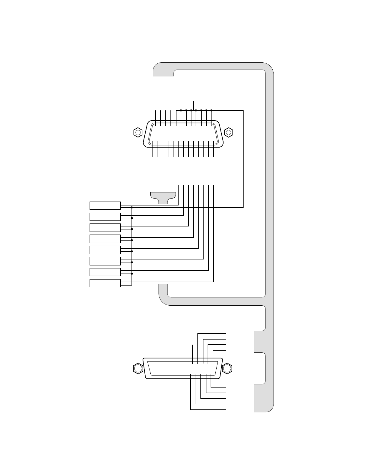
● Control Device Connection on the Remote Site
TRIGGER OUT 8
q
!4 !5 !6 !7 !8 !9 @0 @1 @2 @3 @4 @5
wertyuio!0 !1 !2 !3
TRIGGER OUT 6
TRIGGER OUT 7
TRIGGER OUT 4
TRIGGER OUT 2
G
N
D
G
N
D
TRIGGER OUT 5
TRIGGER OUT 3
TRIGGER OUT 1
SENSOR IN 8
SENSOR IN 7
SENSOR IN 6
SENSOR IN 5
SENSOR IN 4
SENSOR IN 3
SENSOR IN 2
SENSOR IN 1
ALARM
RECALL
OUT
RECOVER OUT
RESET IN
IN
G
Digital Disk Recorder
Sensor
Network Interface Unit
1. SENSOR IN/TRIGGER OUT Connections
Two connection examples are shown in this page, but there may be more applications. Consult the manuals included in
the equipment for the system configuration you need.
<First example>
In the first example, a sensor input lets the Network Interface Unit supply the sensor-related camera picture to the
MON/SPOT terminal. Sensor input signals are relayed to the trigger out terminals. A TRIGGER OUT lets the Digital Disk
Recorder enter the Alarm recording in that the sensor-related images are recorded.
See page 26 for electrical specifications.
24
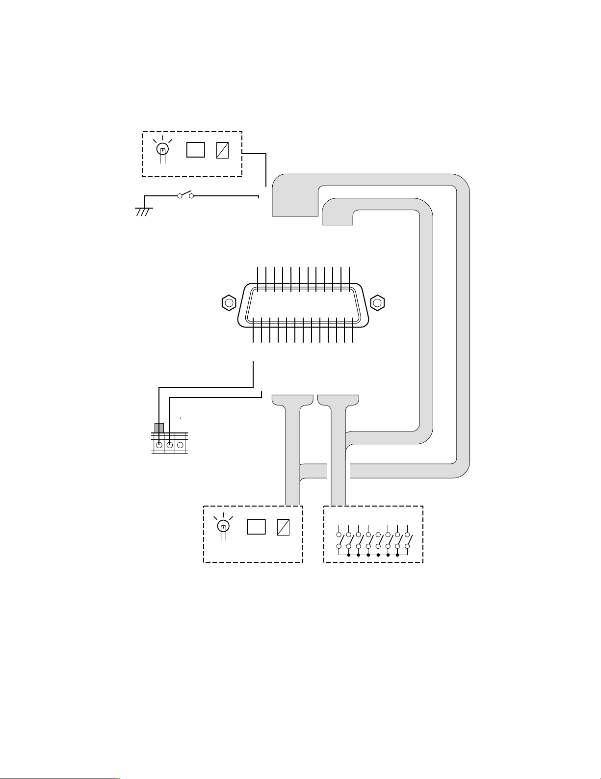
<Second example>
TRIGGER OUT 8
q
!4 !5 !6 !7 !8 !9 @0 @1 @2 @3 @4 @5
wertyuio!0 !1 !2 !3
TRIGGER OUT 6
TRIGGER OUT 7
TRIGGER OUT 4
TRIGGER OUT 2
G
N
D
TRIGGER OUT 5
TRIGGER OUT 3
TRIGGER OUT 1
SENSOR IN 8
SENSOR IN 7
SENSOR IN 6
SENSOR IN 5
SENSOR IN 4
SENSOR IN 3
SENSOR IN 2
SENSOR IN 1
G
N
D
Sensor 8
Sensor 7
Sensor 6
Sensor 5
Sensor 4
Sensor 3
Sensor 2
Sensor 1
!3
@5 @4 @3@2 @1 @0 !9 !8 !7 !6 !5 !4
!2 !1 !0oi ytrewqu
Alarm In 4
Alarm In 3
Alarm In 2
Alarm In 1
GND
Alarm In 5
Alarm In 6
Alarm In 7
Alarm In 8
Open
Network Interface Unit
SENSOR IN/TRIG OUT
Video Multiplexer WJ-FS416
ALARM/REMOTE Connector
In the second example there are 8 sensors relayed to a Video Multiplexer. The Video Multiplexer will enter the Alarm mode
when an alarm is input. For more details, read the manual included in the Multiplexer.
See page 26 for electrical specifications.
25

Sensor In Trigger Out Specifications
Pin# Name Specification/Note
1 GND
2 TRIGGER OUT 7 Open Collector Output, Low Active, Hold Time≈300 ms, Controllable Capacity 25 V DC 50 mA maximum
3 TRIGGER OUT 5 Same as TRIGGER OUT 7
4 TRIGGER OUT 3 Same as TRIGGER OUT 7
5 TRIGGER OUT 1 Same as TRIGGER OUT 7
6 SENSOR IN 8
7 SENSOR IN 7 Same as SENSOR IN 8
8 SENSOR IN 6 Same as SENSOR IN 8
9 SENSOR IN 5 Same as SENSOR IN 8
10 SENSOR IN 4 Same as SENSOR IN 8
11 SENSOR IN 3 Same as SENSOR IN 8
12 SENSOR IN 2 Same as SENSOR IN 8
13 SENSOR IN 1 Same as SENSOR IN 8
Connect an Open Collector or non-voltage make-contact, Low Active (≤0.2 V), Hold Time≥100 ms,
Controllable Capacity 5 V DC maximum
14 TRIGGER OUT 8 Same as TRIGGER OUT 7
15 TRIGGER OUT 6 Same as TRIGGER OUT 7
16 TRIGGER OUT 4 Same as TRIGGER OUT 7
17 TRIGGER OUT 2 Same as TRIGGER OUT 7
18-25 GND
26
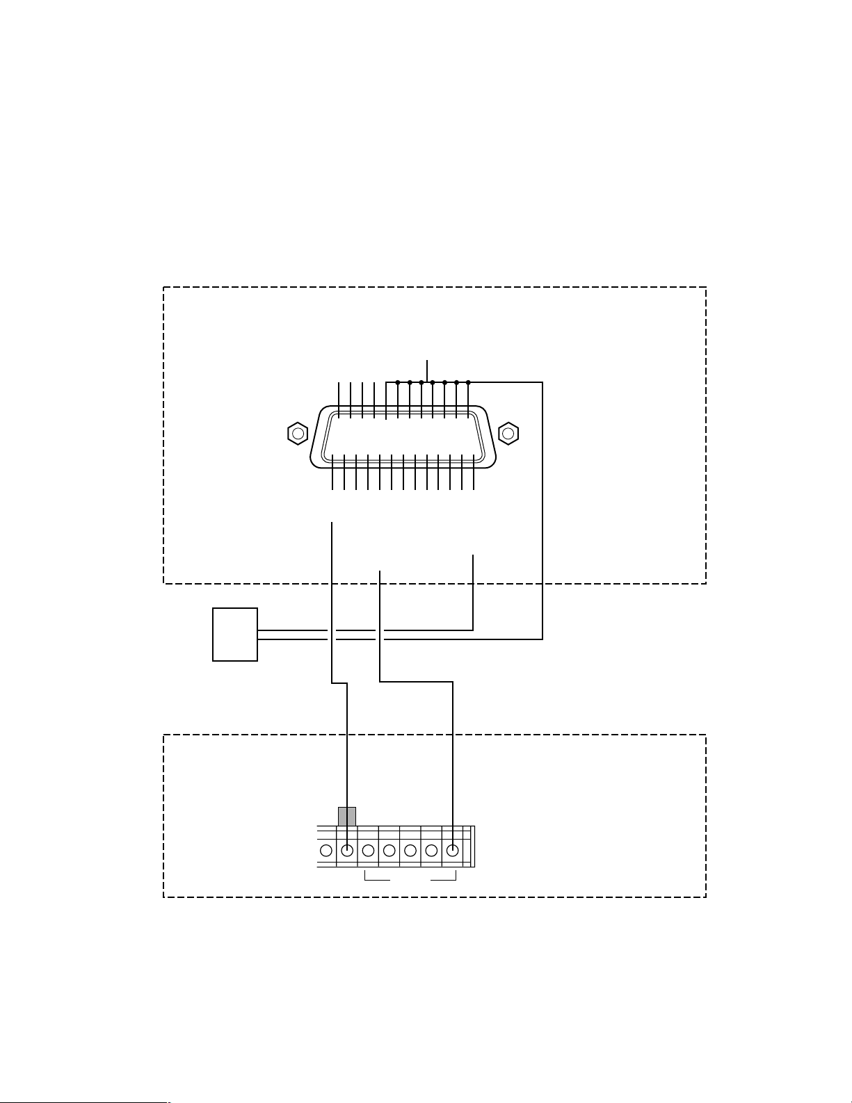
2. PARALLEL IN-OUT Connection
Forced Disconnection
q
!4 !5 !6 !7 !8 !9 @0 @1 @2 @3 @4 @5
wertyuio!0 !1 !2 !3
Mid-Communication OUT
Clock Adjust IN
Strobe OUT
Parallel OUT 8
Parallel OUT 6
Parallel OUT 3
Parallel OUT 1
Parallel IN 8
Parallel IN 6
Parallel IN 4
Parallel IN 2
+12 V OUT
GND
GND
+12 V OUT
Parallel OUT 7
Parallel OUT 5
Parallel OUT 4
Parallel OUT 2
GND
Parallel IN 7
Parallel IN 5
Parallel IN 3
Parallel IN 1
TIME
ADJUST
G
OUT
IN
12345678
BZ
Lamp Buzzer Relay
Auxiliary Control SwitchAuxiliary Devices
BZ
Lamp Buzzer Relay
Auxiliary Devices
Digital Disk
Recorder
The signal inputs entering the parallel inputs 1-8 on the control site are output to the parallel outputs 1-8 on the remote site.
(Similarly, the signals entering the remote site are output to the control site.) If any one of the parallel inputs is closed, then
the corresponding parallel output is generated.
The switches connected to the control site can be used for the shut/release of the electronic lock connected to the parallel
port of the remote site via relays, etc., or for ON/OFF switching of lighting.
● Forced disconnection input terminal
Communication is forcibly finished if the making condition continues for more than 100 ms between the forced
disconnection input terminal and the nearest GND terminal.
● Mid-communication output terminal
When the line is connected and communication is started with the destination, this connector is closed.
There is no perfect coincidence between video or audio
and output timing. This is an open-collector output.
● Strobe output terminal
When data at the parallel output connector is updated,
the strobe pulse output is generated from this connector.
● Clock adjust input terminal
When this input terminal is closed, the clock incorporated in the WJ-NT204 can be corrected. The electrical
conditions are the same as those for parallel input.
Closure should be maintained for more than 100 ms.
27

Parallel In/Out Specifications
Pin# Name Specification/Note
1 GND
2 Clock Adjust In
3 GND Open Collector Output, Low Active, Hold Time≈300 ms, Controllable Capacity 25 V DC 50 mA maximum
4 +12 V Out DC source for relay driving, Current pin#4+#19≤50 mA
5 Parallel Out 7 Open Collector Output, Low Active, Hold Time≈300 ms, Controllable Capacity 25 V DC 50 mA maximum
6 Parallel Out 5 Same as Parallel Out 7
7 Parallel Out 4 Same as Parallel Out 7
8 Parallel Out 2 Same as Parallel Out 7
9 GND
10 Parallel In 7
11 Parallel In 5 Same as Parallel In 7
12 Parallel In 3 Same as Parallel In 7
13 Parallel In 1 Same as Parallel In 7
Forced Disconnection
14
In
Mid-Communication
15
Out
16 Strobe Out
Connect an Open Collector or non-voltage make-contact, Low Active (≤0.2 V), Hold Time≥100 ms,
Controllable Capacity 5 V DC maximum
Connect an Open Collector or non-voltage make-contact, Low Active (≤0.2 V), Hold Time≥100 ms,
Controllable Capacity 5 V DC maximum
Communication Break /Specifications are same as other In terminals.
Active (low) while the unit is in communication/Specifications are same as other Out terminals.
A 300 ms negative pulse generated by any change of the parallel input to update 8 of parallel outputs /
Specifications are same as other Out terminals.
17 Parallel Out 8 Same as Parallel Out 7
18 Parallel Out 6 Same as Parallel Out 7
19 +12v Out DC source for relay driving, Current pin#4+#19≤50 mA
20 Parallel Out 3 Same as Parallel Out 7
21 Parallel Out 1 Same as Parallel Out 7
22 Parallel In 8 Same as Parallel In 7
23 Parallel In 6 Same as Parallel In 7
24 Parallel In 4 Same as Parallel In 7
25 Parallel In 2 Same as Parallel In 7
28
3. Data Communication Connection
ON
OFF
POWER
RS–232C
RS–485
AUX
I N
REMOTE SETUPHOST PORT DATA PORT DATA PORT
10BASE-T/100BASE-TX
OUT
OUT
I N
SENSOR IN/TRIGGER OUT PARALLEL PORT
MON/SPOT AUDIO
ESC
MENU
AF NEAR FARTELE WIDE
Remote Controller WV-CU20
123
456
7809
12345
#
STEP 1
DIAL
PRESET SET
QUICK
STEP 2 STEP 3
CALL
REDIAL
DELETE
ENTER
AUDIO MUTE
ALM ACKVIDEOSWITCH
ONE TOUCH DIAL
AUTO/MANU
SITE
POWER
ON
OFF
ALARM
Data Multiplex Unit WJ-MP204
ALARM
SUSPEND
POWER
ON
OFF
ALARM
Data Multiplex Unit WJ-MP204
ALARM
SUSPEND
POWER
ON
OFF
OPERATE
TIMER HDD
ALARM
SUSPEND
DAYLIGHT
SAVINGS
FULL
LOCK
MEMORY CARD
DISPLAY SELECT
STOP
PLAY REC
PUSH– PAUSE
SET
ALARM SEARCH STEP REW/FF
PLAY MODE SELECT
//
/
/
10/100BASE-T Cable
Cameras
Monitor
WV-CU20
To Network
Remote Site Connection
Data Multiplex Unit
Video Multiplexer
Digital Disk Recorder
Network Interface Unit
(Transmitter)
RS-485 Cable
RS-485 Cable
For maintenance
Set #3 to ON
Connect the 10/100BASE-T terminal to an Ethernet with a 10BASE-T or 100BASE-TX cable.
Connect the RS-485 DATA PORT to other PS
Use the REMOTE terminal to connect WV-CU20 Remote Controller with the supplied cable (6-conductor, straight wiring
included in the WV-CU20) for maintenance.
•
Data equipment with RS-485 cable.
29
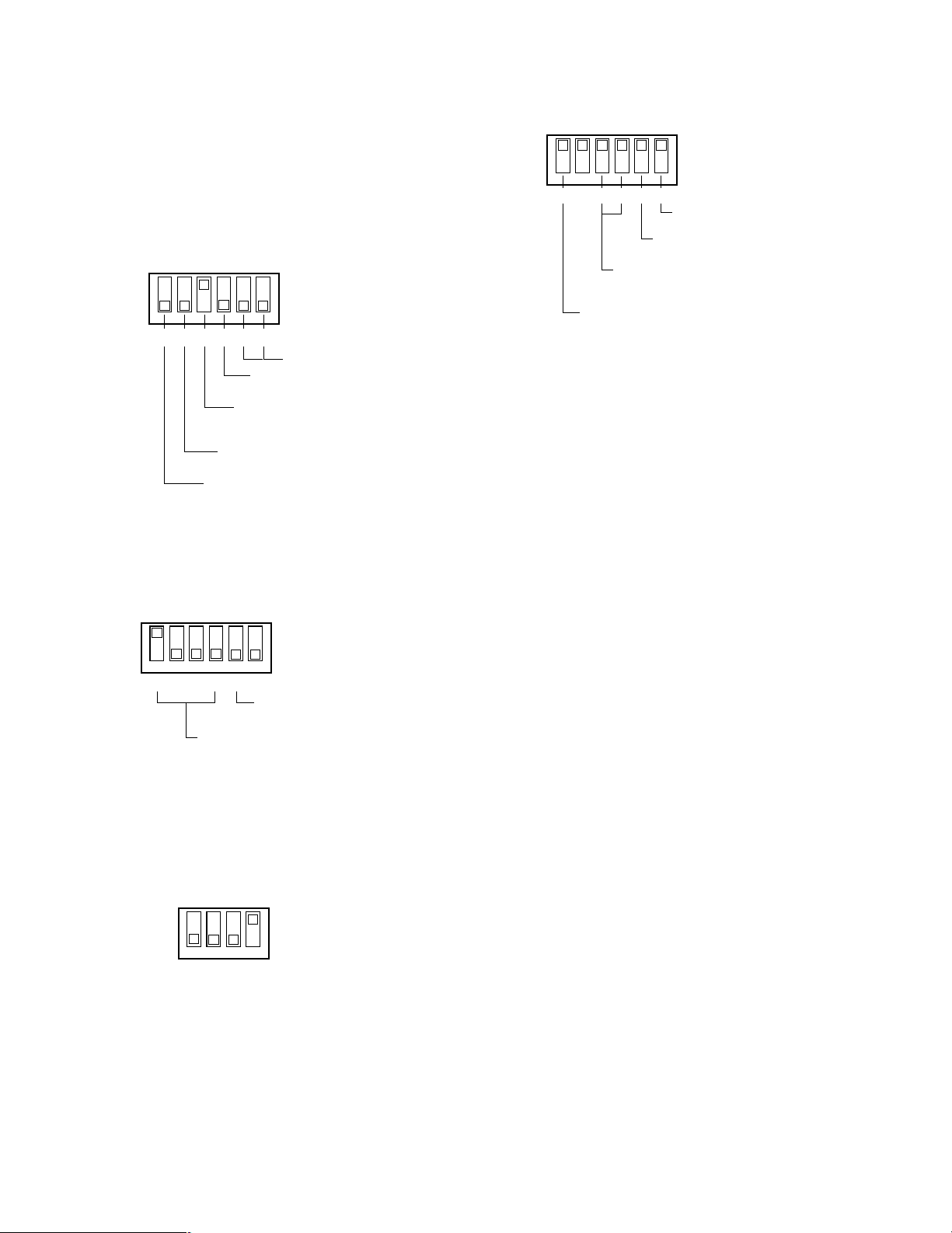
● DIP Switch Setting on the Remote Site
ON
OFF
654321
Keep in the OFF position.
Keep in the OFF position.
RS-485 Wiring Selection
OFF: Straight, ON: Cross
(Change the ON position)
Termination for Remote Site
OFF: Open, ON: Terminate
DATA PORT Selection
OFF: RS-485, ON: RS-232C
WJ-NT204 (Transmitter)
SETUP DIP Switch
1234 56
OFF
ON
Unit Address Bit #1 #2 #3 #4
1 ON OFF OFF OFF
2 OFF ON OFF OFF
3 ON ON OFF OFF
RS-485 Termination
OFF:Open, ON:Terminate
Digital Disk Recorder
WJ-HD100
ON
OFF
Sync Out (VS/VD) Selection
OFF: Looped Through, ON: Internal VD
Termination
OFF: Open, ON: Terminate
Data Line Selection
OFF: 4-Line, ON: 2-Line
Data Communication Mode Bit #3 #4
PS.Data OFF OFF
Camera Mode ON OFF
Data Multiplex Unit
1234 56
ON
OFF
Digital Disk Recorder
WJ-HD500
See the manual included in the peripheral equipment for
more information on DIP switch settings.
1. WJ-NT204
The setting shown in the figure is applied when connecting with PS
Recorder, Data Multiplex Unit and Video Multiplexer on
the Remote site. The termination must be set to ON
when the unit is at the end position in the RS-485 chain,
otherwise keep it in the OFF position.
•
Data devices such as Digital Disk
4. Data Multiplex Unit, WJ-MP204
Set the DIP Switch on the rear of the Data Multiplex Unit
as follows.
2. Digital Disk Recorder, WJ-HD100
Set the DIP Switch on the rear of the Digital Disk
Recorder as follows. Remember the RS-485 line termination rule that is the same as described above.
3. Digital Disk Recorder, WJ-HD500
Set the DIP Switch on the rear of the Digital Disk
Recorder as follows.
30
 Loading...