

Page 1

Quad Unit
WJ-MS488
Before attempting to connect or operate this product, please read these instructions completely
Page 2

The serial number of this product may be found on the
rear of the unit.
You should note the serial number of this unit in the
space provided and retain this book as a permanent
record of your purchase to aid identification in the event
of theft.
Model No.
Serial No.
THIS APPARATUS MUST BE EARTHED.
To ensure safe operation the three-pin plug supplied must be inserted only into a standard three-pin power point which is effectively
earthed through the normal household wiring. Extension cords used
with the equipment must be three-core and be correctly wired to provide connection to earth. Wrongly wired extension cords are a major
cause of fatalities.
The fact that the equipment operates satisfactorily does not imply
that the power point is earthed and that the installation is completely
safe. For your safety, if in any doubt about the effective earthing of
the power point, consult a qualified electrician.
The lightning flash with arrowhead symbol, within an equilateral triangle, is
interned to alert the user to the presence
of uninsulated "dangerous voltage" within the product's enclosure that may be of
sufficient magnitude to constitute a risk
of electric shock to persons.
The exclamation point within an equilateral triangle is intended to alert the user
to the presence of important operating
and maintenance (servicing) instructions
in the literature accompanying the appliance.
WARNING:
TO PREVENT FIRE OR ELECTRIC SHOCK HAZARD, DO NOT EXPOSE THIS APPLIANCE TO RAIN OR MOIS
TURE.
CAUTION:
TO REDUCE THE RISK OF ELECTRIC SHOCK,
DO NOT REMOVE COVER (OR BACK), NO USER
SERVICEABLE PARTS INSIDE.
REFER SERVICING TO QUALIFIED SERVICE
PERSONNEL.
CAUTION
RISK OF ELECTRIC SHOCK
DO NOT OPEN
For Australia
FOR YOUR SAFETY PLEASE READ THE FOLLOWING TEXT CAREFULLY.
This appliance is supplied with a moulded three pin mains plug for your
safety and convenience.
A 13 amp fuse is fitted in this plug.
Should the fuse need to be replaced please ensure that the replacement
fuse has a rating of 13 amp and that it is approved by ASTA or BSI to
BS1362.
Check for the ASTA mark
H or the BSI mark G on the body of the
fuse.
If the plug contains a removable fuse cover you must ensure that it is
refitted when the fuse is replaced.
If you lose the fuse cover the plug must not be used until a replacement
cover is obtained.
A replacement fuse cover can be purchased from your local Panasonic
Dealer.
IF THE FITTED MOULDED PLUG IS UNSUITABLE FOR THE SOCKET OUTLET IN YOUR HOME THEN THE FUSE SHOULD BE
REMOVED AND THE PLUG CUT OFF AND DISPOSED OF SAFELY.
THERE IS A DANGER OF SEVERE ELECTRICAL SHOCK IF THE
CUT OFF PLUG IS INSERTED INTO ANY 13 AMP SOCKET.
If a new plug is to be fitted please observe the wiring code as shown
below.
If in any doubt please consult a qualified electrician.
WARNING: This apparatus must be earthed.
IMPORTANT
The wires in this mains lead are coloured in accordance with the following code.
Green-and-yellow: Earth
Blue: Neutral
Brown: Live
As the colours of the wire in the mains lead of this appliance may not
correspond with the coloured markings identifying the terminals in your
plug, proceed as follows.
The wire which is coloured green-and-yellow must be connected to
the terminal in the plug which is marked with the letter E or by the earth
symbol
I or coloured green or green-and-yellow.
The wire which is coloured blue must be connected to the terminal in
the plug which is marked with the letter N or coloured black.
The wire which is coloured brown must be connected to the terminal
in the plug which is marked with the letter L or coloured red.
How to replace the fuse
Open the fuse compartment with
a screwdriver and replace the fuse
and fuse cover.
For U.K.
CAUTION:
Before attempting to connect or operate this product, please read the label on the bottom.
Page 3

-1-
The Panasonic WJ-MS488 Quad Unit is ideal for CCTV
applications where multiple surveillance cameras are
required. Most 2 : 1 interlace cameras available today,
either colour or black and white, are compatible with the
WJ-MS488. Up to eight cameras may be connected to
the system, and if desired, the monitor can be divided
PREFACE
1. Compatible with Most 2 : 1 Interlace cameras
Advanced digital processing technology allows connection of most 2 : 1 interlace cameras available
today without the requirement for synchronization of
the eight video inputs.
The system may be added to existing security systems and makes possible displays in black and
white or full colour.
2. Alphanumeric Character Generator
Title insertion of up to 8 characters in each of the
windows is possible. This promotes easy identification of the separate camera locations.
3. Alarm with Built-in Buzzer
Upon receiving an alarm signal, a full-sized camera
picture of the site is displayed. By setting the “CAM
TITLE ON” and “ALARM TITLE ON” modes from the
TITLE SETUP menu, “ALARM” and the camera title
will appear intermittently in the picture.
The Automatic alarm reset time is adjustable from 1
to 30 sec.,1, 2, 3, 4, 5 min. or Off.
4. Multi Picture Borderlines
A borderline can be inserted in the quad or 3x3 pictures by setting “BORDER ON” from the SYSTEM
SETUP menu.
5. Two kinds of Video Output Connectors
This system offers two kinds of video output connectors :
FEATURES
(a) VIDEO OUT : A quad, 3x3, or full-size single pic-
ture can be selected with the front panel switches.
(b) VCR OUT : A quad or 3x3 display is always sup-
plied by setting the VCR OUT menu.
6. A back-up memory inside maintains preset title
character information.
7. Video Loss Checking Function
If the video signal is lost due to a disconnected
cable or other reasons, an alarm buzzer beeps and
a caution message is displayed on the monitor
screen.
8. Using RS232C connector by connecting with computer makes possible to remote access with no distance limit.
9. The Quad Shift function allows you to shift between
two quad pictures (each consisting of 4 picture segments).
10. Pauses can be inserted in the pictures (STILL
mode) only in multi picture mode when monitoring
camera picture.
11. You can monitor sequentially, full-size single or multi
pictures (quad or 3x3).
up to nine windows (3x3) for simultaneous display of the
nine different images.
Simple front panel switch operation allows quick selection between single, quad, and 3x3 camera display
modes.
PREFACE ................................................................... 1
FEATURES ................................................................. 1
PRECAUTIONS .......................................................... 2
MAJOR OPERATING CONTROLS AND
THEIR FUNCTIONS ................................................... 3
RACK MOUNTING ..................................................... 6
SETTING UP THE MENUS ......................................... 7
CONTENTS
OPERATION ............................................................... 15
SYSTEM CONNECTIONS .......................................... 22
BLOCK DIAGRAM ..................................................... 26
APPENDIX .................................................................. 27
SPECIFICATIONS ...................................................... 29
STANDARD ACCESSORIES ...................................... 29
Page 4

-2-
PRECAUTIONS
• Refer all work related to the installation of this
pro-duct to qualified service personnel or system
installers.
• Do not block the ventilation opening or slots on
the cover.
To prevent the appliance from overheating, place it
at least 5 cm (2 inches) away from the wall.
• Do not drop metallic parts through slots.
This could permanently damage the appliance. Turn
the power off immediately and contact qualified service personnel for service.
• Do not attempt to disassemble the appliance.
To prevent electric shock, do not remove screws or
covers.
There are no user-serviceable parts inside. Contact
qualified service personnel for maintenance.
• Handle the appliance with care.
Do not strike or shake, as this may damage the
appliance.
• Do not expose the appliance to water or moisture, nor try to operate it in wet areas.
Do take immediate action if the appliance becomes
wet. Turn the power off and refer servicing to qualified service personnel. Moisture may damage the
appliance and also cause electric shock.
• Do not use strong or abrasive detergents when
cleaning the appliance body.
Use a dry cloth to clean the appliance when it is
dirty.
When the dirt is hard to remove, use a mild detergent and wipe gently.
• Do not operate the appliance beyond its specified temperature, humidity or power source ratings.
Do not use the appliance in an extreme environment
where high temperature or high humidity exists.
Use the appliance at temperatures within –10°C to
+50°C (14°F to 122°F) and a humidity below 90%.
The input power source for this appliance is 220 240 V AC 50 Hz.
Page 5

-3-
1. Power ON/OFF Switch (POWER)
This switch turns the power of this unit on or off. The
POWER indicator lights when the power of this unit
is on.
Switch Protector (Standard Accessory)
To prevent that the power of this unit is turned off accidentally, install the supplied switch protector as shown
below.
• MULTISCREEN button
Pressing this button changes the camera picture to
quad picture (QUAD A or QUAD B) or to 3x3 picture. To display the multiscreen, the setting of the
VTR OUT menu is required. See page 8 for details.
• QUAD SHIFT button
When monitoring a quad picture, pressing this button shifts to another quad picture.
4. VIDEO SELECT (1....8)/CURSOR
(CC,DD,AA, BB)/SELECT (–, +) Buttons
These buttons select the video signal to monitor it in
full-size single picture or move the cursor on the
setup menus.
• VIDEO SELECT (1....8) buttons
When the setup menu is not displayed, these button
work as VIDEO SELECT button.
Pressing one of these buttons selects a channel to
be displayed in single picture mode.
The indicator in the button lights to indicate the
number of the selected camera.
• CURSOR (CC,DD,AA, BB)/SELECT (–, +) buttons
When the setup menu is displayed, these buttons
work as CURSOR (CC,DD,AA, BB)/SELECT (–, +) but-
tons.
Pressing these buttons moves the cursor or selects
a mode or a parameter.
Except for buttons No. 7 and 8, the function of these
buttons according to the selected mode. The functions of each button are as follows:
MAJOR OPERATING CONTROLS AND THEIR FUNCTIONS
SIGNAL
GND
RS-232CPLAY IN ALARM/REMOTE
(VS1Vp-p)
GENLOCK
IN
VIDEO
OUT
GENLOCK
OUT
VTR
OUT
OUT
IN
765
VIDEO
321
876544321
8
85 7641 32
POWER ALARM
MULTISCREEN
QUAD SHIFT
CURSOR
VIDEO SELECT
SELECT
ALARM RESET
ON
OFF
ESC
MENU MODE
SEQ
SET/
RESET
PLAY
EL-ZOOM
STILL
MODE SELECT
Quad System WJ-MS
SWITCH
PROTECTER
SWITCH
PROTECTOR
2. Alarm LED (ALARM)
This LED flashes to indicate an alarm condition
exists.
It changes to steady light when the alarm is reset
automatically.
To turn the LED off, press the ALARM RESET/QUAD
SHIFT/MULTISCREEN button.
3. Alarm Reset/Quad Shift/Multiscreen Button
(ALARM RESET/QUAD SHIFT/MULTISCREEN)
This button has different functions in different
modes, as described below.
• ALARM RESET button
When an alarm signal is received, this button works
as the ALARM RESET button.
Pressing this button in an alarm situation cancels
the alarm mode with the following results:
1. The alarm LED stops flashing.
2. The alarm output is stopped.
3. The alarm buzzer stops beeping.
4. The video loss caution message on the monitor
screen disappears.
Page 6

-4-
Button No. 1 (CC) Button
Moves the cursor downward when the setup menu
is monitored.
Moves the zoomed picture to downward when the
zoomed picture is monitored.
Button No. 2 (DD) Button:
Moves the cursor upward when the setup menu is
monitored.
Moves the zoomed picture to upward when the
zoomed picture is monitored.
Button No. 3 (AA) Button
Moves the cursor on the menu when the setup menu
is monitored.
Moves the zoomed picture to left when the zoomed
picture is monitored.
Button No. 4 (BB) Button
Moves the cursor on the menu when the setup menu
is monitored.
Moves the zoomed picture to right when the
zoomed picture is monitored.
Button No. 5 (–) Button
Zooms out the zoomed picture displayed on the
monitor screen.
Moves the character selection cursor in reverse
alphabetical order.
Button No. 6 (+) Button
Zooms the picture currently displayed on the monitor screen.
Moves the character selection cursor in alphabetical
order.
5. Menu/Escape Button (MENU/ESC)
This button has different functions in different
modes, as described below.
• MENU button
When monitoring picture, this button works as the
MENU button. Pressing this button for approx. 2
seconds displays the MAIN menu. Pressing it again
cancels the display of the MAIN menu.
• ESC button
When the setup menu (MAIN) is displayed on the
monitor screen, this button works as the ESC button.
Pressing this button returns to picture monitoring
from the MAIN menu.
Pressing this button returns to the previous setup
menu during the setup.
6. Mode Button (MODE)
This button selects mode from SEQ, PLAY, ELZOOM, or STILL. Press this button to select the
desired mode. The modes you can select are as follows:
SEQ: When this mode is selected, the currently
monitoring pictures are displayed in the sequential order with the dwell time you set on the SEQ
SETUP menu. See page 12 for details.
Note: To use this mode for multi picture, setting
of the VTR OUT menu is required in advance. See page 8 for details.
PLAY: When this mode is selected, the playback
picture from the VTR that is connected with the
PLAY IN connector on the rear panel is displayed on the monitor screen. See page 19 for
details.
Note: The full-size single picture is not recorded
on VTR.
EL-ZOOM: When this mode is selected, the select-
ed playback picture is zoomed in or out by
operating the CURSOR (CC, DD, AA, BB) and the
SELECT (+, –) buttons. See page 20 for details.
Note: This mode is not available when the full-
size single picture or camera picture is monitored.
STILL: When this mode is selected, the selected
picture appears still on the monitor screen. See
page 18 for details.
Note: This mode is not available when the full-
size single picture or playback picture is
monitored.
7. Mode Indicators (SEQ, PLAY, EL-ZOOM, STILL)
These indicators are used to select desired mode.
Note: These indicators are used only to select the
mode. These do not indicate an activating
mode. To check the activating mode, refer “To
Check the Current Mode” on page 15.
8. Set/Reset Button (SET/RESET)
This button sets the mode that is selected by pressing the MODE button. Press this button after selecting desired mode by the MODE button.
To reset the mode, press this button after selecting
the mode to be reset by the MODE button.
9. Video Input Connector (VIDEO IN 1....8)
These connectors accept a composite video signal
from a camera.
They are automatically terminated.
Note: If the input signals have a high jitter content,
as in the case of a VTR playback picture, it may
not be possible to synchronize this unit.
10. Video Output Connectors (VIDEO OUT 1....8)
The video input signals connected to the VIDEO IN
connector are looped through to these connectors
with an automatic 75Ω termination.
Page 7

-5-
11. Video Output Connector (VIDEO OUT)
The video signal selected by the ALARM RESET/
QUAD SHIFT/MULTISCREEN button (quad or 3x3)
or the VIDEO SELECT button (full-size single picture) is supplied to the Video Monitor from this connector.
12. VTR Output Connector (VTR OUT)
The video signal for the multi picture mode (QUADA, QUAD-B, or 3x3) is always provided at this connector. By connecting it to the VIDEO IN connector
of the VTR, you can record the quad or 3x3 picture.
13. Gen-Lock In Connector (GEN-LOCK IN)
The VS signals (B/W composite signal or composite
sync signal) is supplied to this connector for external synchronization.
14. Gen-Lock Out Connector (GEN-LOCK OUT)
The VS signals (B/W composite signal or composite
sync signal) connected to the Gen-Lock In connector is looped through to this connector. The connector connected with a coaxial cable to this connector
cancels the termination.
15. Play Input Connector (PLAY IN)
The playback signal from the VTR is supplied to this
connector.
16. Alarm/Remote Control Connector
(ALARM/REMOTE)
This connector accepts the alarm signal from associated alarm sensor units or the remote control signal from the external equipment. See page 25 for
details.
17. RS232C Connector (RS232C)
Connecting a PC to this connector will allow you to
remote control to monitor.
18. Ground Terminal (GND)
19. Power Cord
Page 8
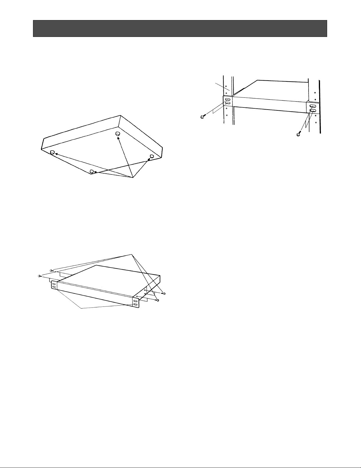
-6-
To install the WJ-MS488 Quad Unit in an EIA 19-inch
rack, use the rack mounting brackets (provided) and
eight screws (provided, M3x10).
1. Turn off the power of the unit.
2. Remove the four screws fixing the rubber legs, and
remove the four rubber legs from the unit.
RACK MOUNTING
Remove four rubber legs.
3. Attach the rack mounting brackets on both sides
and fix them with eight screws (provided).
Eight screws (Provided)
4. Install the unit in the rack with four screws (to be
procured locally).
Cautions:
1. Leave one space free both above and below the
unit, or install a cooling fan in the rack.
Do not block the ventilation opening or solts in the
cover to prevent the appliance from overheating.
Always keep the temperature in the rack within 50°C
(122°F).
2. If the rack is subject to vibrations, secure the rear of
the unit to the rack using additional rack mounting
brackets (to be procured locally).
EIA 19”
rack
Fix the rack mounting brackets
Page 9
MENU
ESC
** MAIN **
SYSTEM SETUP
*
ALARM BUZZER 2SEC
ALARM OUT 2SEC
ALARM AUTO RESET OFF
SEQ SETUP
*
TITLE SETUP
*
CH SETUP
*
-7-
Before the Settings
1. Confirm that the cameras and peripherals are connected correctly and firmly.
2. Turn on the power of this unit and connected
peripherals.
1. Displaying the Menus
Press the MENU button for 2 seconds or more.
The MAIN menu appears.
You can setup the following items:
• SYSTEM SETUP
• ALARM BUZZER
• ALARM OUT
• ALARM AUTO RESET
• SEQ SETUP
• TITLE SETUP
• CH SETUP
See the following pages for details about the functions and settings.
2. How to Operate the Menus
Precaution:
Entering the setup menu is not possible while
the ALARM LED is flashing. Make sure the alarm
mode is canceled. To cancel the alarm mode,
press the ALARM RESET button.
To select the desired item, press the CURSOR
(CC,DD,AA, BB) buttons. Each time you press a button,
the cursor moves to the next (CC, BB) or previous (DD,
AA) item.
SETTING UP THE MENUS
To select the desired parameter of the selected
item, press the SELECT (–, +) buttons.
5 6
To return to normal picture, press the MENU button
when the MAIN menu is displayed.
Note:
Some items have a sub menu (The
“
*
”
mark
indicates that a setting menu exists, for example, SYSTEM SETUP.), press the SELECT (–, +)
buttons to display the selected sub menu.
To return to the previous menu, press the MENU
button again.
All Reset Operation
All reset allows you to reset all setup menu items to
the factory settings if you are unsure about the correct settings.
Proceed as follows:
1. Turn the power of this unit off.
2. While holding down the (BB), (+), and MENU
button simultaneously, and press the POWER
button.
The buzzer beeps when all settings are reset to
the factory settings.
41 32
Page 10

-8-
3-1-1. Border (BORDER)
This parameter lets you set the appearance of the borders that divide the monitor screen.
1. Move the cursor to the BORDER parameter.
2. Select the desired colour of the borders.
OFF: No borders
BLACK: Black Borders
GREY: Grey Borders
WHITE: White Borders
The initial factory setting is WHITE.
** SYSTEM SETUP **
BORDER WHITE
VTR OUT *
AUTO SKIP OFF
VIDEO LOSS ON
ZOOM SETUP *
START SCREEN 3x3
PLAY TITLE ON
STILL-SEL TITLE ON
5 6
** SYSTEM SETUP **
BORDER WHITE
VTR OUT *
AUTO SKIP OFF
VIDEO LOSS ON
ZOOM SETUP *
START SCREEN 3x3
PLAY TITLE ON
STILL-SEL TITLE ON
** SYSTEM SETUP **
BORDER WHITE
VTR OUT *
AUTO SKIP OFF
VIDEO LOSS ON
ZOOM SETUP *
START SCREEN 3x3
PLAY TITLE ON
STILL-SEL TITLE ON
Borderline
3-1-2. VTR Output (VTR OUT)
This parameter lets you select the multi pictures to be
recorded on a VTR.
1. Move the cursor to VTR OUT.
3. Setup Menu Description
3-1. SYSTEM SETUP
The SYSTEM SETUP menu lets you set the following items:
• BORDER
• VTR OUT
• AUTO SKIP
• VIDEO LOSS
• ZOOM SETUP
• START SCREEN
• PLAY TITLE
• STILL-SEL TITLE
1. Move the cursor to SYSTEM SETUP.
2. Press one of the SELECT (–, +) buttons. The SYSTEM SETUP menu appears on the monitor screen.
Note: To return to the MAIN menu, press the MENU
button.
2. Press the SELECT (+, –) buttons. The VTR OUT
menu appears on the monitor screen.
3 Move the cursor to the parameters and select ON or
OFF.
ON: The picture is recorded with the selected mode
(3x3, QUAD-A, or QUAD-B) on a VTR.
OFF: The selected multi picture mode is not avail-
able for displaying the picture on the monitor
screen and recording on a VTR.
The factory setting is 3x3.
Notes:
• Setting all parameters to OFF is not available.
• If the parameter selected for START SCREEN on
the SYSTEM SETUP menu is set to OFF on the
VTR OUT menu, it will be automatically changed
to ON.
Refer to the Startup Screen on page 10 for detail
setting.
**VTR OUT**
QUAD A OFF
QUAD B OFF
3x3 ON
Page 11

-9-
3-1-3. Auto Channel Skipping (AUTO SKIP)
This parameter lets you enable or disable automatic
skipping of channels to which no camera is connected.
1. Move the cursor to the AUTO SKIP parameter.
** SYSTEM SETUP **
BORDER WHITE
VTR OUT *
AUTO SKIP OFF
VIDEO LOSS ON
ZOOM SETUP *
START SCREEN 3x3
PLAY TITLE ON
STILL-SEL TITLE ON
** SYSTEM SETUP **
BORDER WHITE
VTR OUT *
AUTO SKIP OFF
VIDEO LOSS OFF
ZOOM SETUP *
START SCREEN 3x3
PLAY TITLE ON
STILL-SEL TITLE ON
2. Select ON or OFF.
ON: Channels to which no camera is connected are
skipped when the sequence mode is selected.
Note: When QUAD-A, QUAD-B, or 3x3 is dis-
played on the monitor screen, the multi picture is skipped only when no camera is connected to all of the channels.
OFF: No channels are skipped.
1
2
3
4
1
3
4
d
3-1-4. Video Loss Checking (VIDEO LOSS)
This parameter lets you activate a function that checks
whether the video signal is being supplied to the VIDEO
IN connector.
1. Move the cursor to the VIDEO LOSS parameter.
2. Select ON or OFF.
ON: When video loss is detected, the picture
switches to the quad format. The message
“CHXX LOSS” appears on the monitor screen
and the alarm buzzer starts beeping.
OFF: The video loss alarm is ignored.
3-1-5. Zoom Setting (ZOOM SETUP)
The ZOOM SETUP menu lets you set the following
items:
• ZOOM POSITION
• ZOOM TITLE
1. Move the cursor to ZOOM SETUP.
2. Press one of the SELECT buttons (+ or −). The
ZOOM SETUP menu appears on the monitor screen.
3-1-5-1. Zooming Position (ZOOM POSITION)
This parameter lets you select whether to display the
zoomed picture in fixed area or variable when the playback multi picture (quad or 3x3) is monitored.
1. Move the cursor to ZOOM POSITION parameter.
** SYSTEM SETUP **
BORDER WHITE
VTR OUT *
AUTO SKIP OFF
VIDEO LOSS OFF
ZOOM SETUP *
START SCREEN 3x3
PLAY TITLE ON
STILL-SEL TITLE ON
** ZOOM SETUP **
ZOOM POSITION QUADRANT
ZOOM TITLE ON
Page 12

-10-
No. 1
button
No. 2
button
No. 3
button
No. 4
button
2. Select QUADRANT or VARIABLE.
QUADRANT: When the playback multi picture
(QUAD-A, QUAD-B, or 3x3) is monitored, pressing a desired VIDEO SELECT (1, 2, 3, or 4) button switches the currently monitored multi picture to twofold zoomed picture of the selected
fixed area.
The VIDEO SELECT (1, 2, 3, or 4) buttons select
following fixed areas. See page 20 for operation.
VARIABLE: When the playback multi picture is
monitored, the position to be zoomed is selectable by pressing the CURSOR (CC, DD, AA, BB) in
EL-ZOOM mode.
See page 21 for operation.
Note: This function is available only when the
playback multi picture is monitored.
3-1-5-2. Zoom Title (ZOOM TITLE)
This parameter lets you enable or disable “ZOOM” display on the monitor screen when zoomed playback picture is monitored.
1. Move the cursor to ZOOM TITLE parameter.
2. Select ON or OFF.
ON: “ZOOM” is displayed.
OFF: “ZOOM” is not displayed.
Notes:
• Moving the position of the title is not available.
• When the camera title is displayed upper side of
the monitor screen, the zoom title is displayed in
the bottom of the right corner of the monitor
screen.
** SYSTEM SETUP **
BORDER WHITE
VTR OUT *
AUTO SKIP OFF
VIDEO LOSS OFF
ZOOM SETUP *
START SCREEN 3x3
PLAY TITLE ON
STILL-SEL TITLE ON
3-1-6. Startup Screen (START SCREEN)
This parameter lets you select a display pattern for your
startup screen. When the power is turned on, the picture
is displayed in the selected pattern.
1. Move the cursor to the START SCREEN parameter.
ZOOM-PLAY
2. Select one of the desired pattern.
QUAD-A: The QUAD-A picture is displayed. You
can select channels to be displayed for QUADA on the CH SETUP menu. See page 14 for
details.
QUAD-B: The QUAD-B picture is displayed. You
can select channels to be displayed for QUADB on the CH SETUP menu. See page 14 for
details.
3x3: Nine screen segments (3x3) are displayed.
FULL: A full-size single picture is displayed.
1-SEQ: A sequence of a full-size single picture is
displayed.
4-SEQ: A sequence of quad pictures is displayed.
Note: If you select QUAD-A, QUAD-B, or 3x3 on the
START SCREEN menu, set the selected parameter to ON on the VTR OUT menu. When OFF
is selected on the VTR OUT menu, the parameter selected on the START SCREEN menu will
be automatically changed to ON on the VTR
OUT menu.
3-1-7. Play Title (PLAY TITLE)
This parameter lets you enable or disable “PLAY” display on the monitor screen when playback picture is
monitored.
1. Move the cursor to the PLAY TITLE parameter.
** SYSTEM SETUP **
BORDER WHITE
VTR OUT *
AUTO SKIP OFF
VIDEO LOSS OFF
ZOOM SETUP *
START SCREEN 3x3
PLAY TITLE ON
STILL-SEL TITLE ON
2. Select ON or OFF.
ON: “PLAY” is displayed.
OFF: “PLAY” is not displayed.
Note: Moving the position of the title is not available.
** ZOOM SETUP **
ZOOM POSITION QUADRANT
ZOOM TITLE ON
Page 13

-11-
** MAIN **
SYSTEM SETUP
*
ALARM BUZZER 2SEC
ALARM OUT 2SEC
ALARM AUTO RESET OFF
SEQ SETUP
*
TITLE SETUP
*
CH SETUP
*
OFF 1SEC 2SEC
......
30SEC
1MIN
......
5MIN EXT
3-3. ALARM OUT
This parameter lets you select the duration the alarm
signal is output.
1. Move the cursor to ALARM OUT.
2. Select the desired duration the alarm signal is output.
1-30 SEC, 1-5 MIN: The alarm signal is output for
the duration you set.
3-1-8. Still Mode Selected Channel Title (STILL-SEL TITLE)
This parameter lets you enable or disable “STILL?” display on the monitor screen when the the still mode is
activating.
1. Move the cursor to the STILL-SEL TITLE parameter.
** MAIN**
SYSTEM SETUP
*
ALARM BUZZER 2SEC
ALARM OUT 2SEC
ALARM AUTO RESET OFF
SEQ SETUP
*
TITLE SETUP
*
CH SETUP
*
1SEC
......
30SEC 1MIN
......
5MIN
3-2. ALARM BUZZER
This parameter lets you select the beeping duration of
alarm buzzer when alarm is activated.
1. Move the cursor to ALARM BUZZER.
2. Select the buzzer time.
OFF: Disables alarm buzzer output.
1-30 SEC, 1-5 MIN: The buzzer keeps on beeping
for the duration you set.
EXT: The alarm buzzer keeps on beeping until the
alarm recover signal is received from an external equipment, such as a VTR.
** SYSTEM SETUP **
BORDER WHITE
VTR OUT *
AUTO SKIP OFF
VIDEO LOSS OFF
ZOOM SETUP *
START SCREEN 3x3
PLAY TITLE ON
STILL-SEL TITLE ON
3-4. ALARM AUTO RESET
This parameter lets you select the duration that the
alarm is automatically reset after the selected duration
has passed (programmed).
1. Move the cursor to ALARM AUTO RESET.
2. Select the desired curation.
OFF: The alarm condition continues until the
ALARM RESET button on the front panel is
pressed or the alarm recover signal from the
VTR is supplied to the ALARM/REMOTE connector.
1-30 SEC, 1-5 MIN: The alarm condition is automati-
cally reset after the selected duration has
passed.
** MAIN **
SYSTEM SETUP
*
ALARM BUZZER 2SEC
ALARM OUT 2SEC
ALARM AUTO RESET OFF
SEQ SETUP
*
TITLE SETUP
*
CH SETUP *
OFF 1SEC
......
30SEC 1MIN
......
5MIN
2. Select ON or OFF.
ON: “STILL?” is displayed.
OFF: “STILL?” is not displayed.
Note: Moving the position of the title is not available.
Page 14

-12-
3-5. SEQ SETUP
This parameter lets you set the sequential order and
dwell time for camera switching.
Note: Before you set up the SEQ SETUP menu, the set-
ting of the VTR OUT menu is required.
1. Move the cursor to SEQ SETUP.
2. Press one of the SELECT (–, +) buttons. The SEQ
SETUP menu appears on the monitor screen, and “1
CH” starts blinking.
** MAIN **
SYSTEM SETUP
*
ALARM BUZZER 2SEC
ALARM OUT 2SEC
ALARM AUTO RESET OFF
SEQ SETUP
*
TITLE SETUP
*
CH SETUP
*
** SEQ SETUP **
FULL SEQ QUAD SEQ
1: 1CH 2SEC 1: 4A 2SEC
2: 2CH 2SEC 2: 4B 2SEC
3: 3CH 2SEC
4: 4CH 2SEC
5: 5CH 2SEC
6: 6CH 2SEC
7: 7CH 2SEC
8: 8CH 2SEC
9: OFF
10: OFF
5 6
** SEQ SETUP **
FULL SEQ QUAD SEQ
1: 1CH 2SEC 1: 4A 2SEC
2: 2CH 2SEC 2: 4B 2SEC
3: 3CH 2SEC
4: 4CH 2SEC
5: 5CH 2SEC
6: 6CH 2SEC
7: 7CH 2SEC
8: 8CH 2SEC
9: OFF
10: OFF
4. Move the cursor to dwell time area by pressing the
CURSOR (CC,DD,AA, BB) buttons.
5. Select the deisred dwell time by pressing the
SELECT (–, +) buttons. The dwell time changes as
below:
1SEC 2SEC 3SEC • • • • 30SEC
6. Repeat steps 3 to 5 to determine the sequential
order and dwell time for others.
Note: The picture is recorded in QUAD-A, QUAD-B, or
3x3 according to the settings of the VTR OUT menu.
In FULL SEQ, the order and the dwell time of the
pictures to be recorded may be changed if QUADA, QUAD-B, or 3x3 is assigned in the FULL SEQ
order.
<QUAD SEQ Setup>
7. Select the desired dwell time for QUAD-A or QUADB by pressing the SELECT(–, +) buttons.
<FULL SEQ Setup>
3. Select the desired channel or multiscreen pattern by
pressing the SELECT (–, +) buttons.
1CH 2CH 3CH
4CH 5CH 6CH 7CH
OFF 3x3 4B (QUAD-B) 4A (QUAD-A) 8CH
** TITLE SETUP **
CAM TITLE ON
TITLE SET
*
TITLE POSI
*
ALARM TITLE ON
STILL TITLE ON
** MAIN **
SYSTEM SETUP
*
ALARM BUZZER 2SEC
ALARM OUT 2SEC
ALARM AUTO RESET OFF
SEQ SETUP
*
TITLE SETUP
*
CH SETUP
*
5 6
3-6. TITLE SETUP
A title consisting of up to 8 alphanumeric characters
can be displayed on the monitor.
1. Move the cursor to TITLE SETUP.
2. Press one of the SELECT (– , +) buttons. The TITLE
SETUP menu appears on the monitor screen.
Page 15

-13-
You can set the following items:
• CAM TITLE
• TITLE SET
• TITLE POSI
• ALARM TITLE
• STILL TITLE
Note: To return to the MAIN menu, press the ESC
button.
3-6-1. CAM TITLE
This parameter lets you enable or disable the camera
title display on the monitor screen.
1. Move the cursor to the CAM TITLE parameter.
2. Select ON or OFF.
ON: Title display.
OFF: No title display.
** TITLE SETUP **
CAM TITLE ON
TITLE SET
*
TITLE POSI
*
ALARM TITLE ON
STILL TITLE ON
3-6-2. TITLE SET
This parameter lets you edit a camera title.
1. Move the cursor to TITLE SET.
2. Press one of the SELECT (–, +) buttons. The EDITTING menu appears on the monitor screen and “1”
starts blinking.
3. Move the cursor to the channel number whose title
is to be edited by pressing the CURSOR (CC,DD,AA,
BB) buttons.
4. Select a character by pressing the SELECT (–, +)
buttons.
5. After selecting the first character, press the CURSOR button (BB). Then select the second character.
6. Repeat steps 3 to 5 above to complete the title.
7. Repeat steps 3 to 6 to edit the other channels.
8. Press the ESC button to return to the previous
menu.
** TITLE SETUP **
CAM TITLE ON
TITLE SET
*
TITLE POSI
*
ALARM TITLE ON
TITLE EDIT ON
STILL ALARM ON
** TITLE **
1: 1.......
2: 2.......
3: 3.......
4: 4.......
5: 5.......
6: 6.......
7: 7.......
8: 8.......
41 32
Camera title edit area
Channel numbers
ABCDEFGHIJKLM
NOPQRSTUVWXYZ
ДЬЦЖСЕШ
0123456789
←→=?'"#&()*+,
-./:;
E
(blank)
To erase a specific character
1. Select a character to be erased.
2. Select “•” (blank mark) to erase the character.
To erase the title of a specific channel
1. Move the cursor to a character of the title to be
erased.
2. Press the SELECT (– and +) buttons simultaneously.
3-6-3. TITLE POSI
This parameter lets you select the position on the monitor screen where you want the title to be displayed.
1. Move the cursor to TITLE POSI.
2. Press one of the SELECT (–, +) buttons. The TITLE
POSITION menu appears with the title of the channel 1 on the monitor screen.
3. Select the position where the title is to be displayed
by pressing the CURSOR (CC,DD,AA, BB) buttons.
4. Press the MENU button to return to the previous
menu.
** TITLE SETUP **
CAM TITLE ON
TITLE SET
*
TITLE POSI
*
ALARM TITLE ON
STILL TITLE ON
Page 16

-14-
ALARM
3-6-5. STILL TITLE
This parameter lets you enable or disable "STILL" display while a picture is paused.
1. Move the cursor to the STILL TITLE parameter.
2. Select ON or OFF.
ON: “STILL” is displayed
OFF: “STILL” is not displayed
** TITLE SETUP **
CAM TITLE ON
TITLE SET
*
TITLE POSI
*
ALARM TITLE ON
STILL TITLE ON
STILL?
STILL
3-7. CH SETUP
This parameter lets you select the position where the
camera picture will be displayed on the multi screen.
Note: Before you set up the CH SETUP menu, the set-
ting of the VTR OUT menu is required.
1. Move the cursor to CH SETUP.
2. Press the SET button. The CH SETUP menu appears
on the monitor screen.
3. Move the cursor to the number of the picture segment in the multi screen by pressing the CURSOR
(CC, DD, AA, BB) buttons.
4. Select the channel number to be assigned to the
selected picture segment by pressing the SELECT
(–, +) buttons.
5. Repeat steps 3 and 4 above to assign the other
channels to the picture segments.
6. Press the SET button to finalize channel assignment.
Notes:
• QUAD A consists of QUAD SET 1-4, and QUAD
B consists of QUAD SET 5-8.
• When OFF is selected, no picture assigned for
that channel so that no picture is displayed on
the monitor screen.
• When OFF is selected, “CHXX LOSS” does not
appear for that channel on the monitor screen if
the video loss alarm is detected even though the
VIDEO LOSS parameter is ON.
** MAIN **
SYSTEM SETUP
*
ALARM BUZZER 2SEC
ALARM OUT 2SEC
ALARM AUTO RESET OFF
SEQ SETUP
*
TITLE SETUP
*
CH SETUP
*
**CH SETUP**
3X3 SET QUAD SET
1: 1CH 1: 1CH
2: 2CH 2: 2CH
3: 3CH 3: 3CH
4: 4CH 4: 4CH
5: 5CH 5: 5CH
6: 6CH 6: 6CH
7: 7CH 7: 7CH
8: 8CH 8: 8CH
9: OFF
Note: All channel titles will be displayed in the same
position. You cannot specify a different position
for each title.
3-6-4. ALARM TITLE
This parameter lets you enable or disable "ALARM" display when the alarm is activated.
1. Move the cursor to ALARM TITLE .
2. Select ON or OFF.
ON: “ALARM” is displayed
OFF: “ALARM” is not displayed.
1 (5) 2 (6)
3 (9) 4 (8)
123
456
789
** TITLE SETUP **
CAM TITLE ON
TITLE SET
TITLE POSI
ALARM TITLE ON
STILL TITLE ON
*
*
Page 17

-15-
With this unit, different multi picture never can be sent to
the VTR OUT connector (VTR) and the VIDEO OUT connector (Video Monitor) simultaneously. See block diagram of this unit on page 26.
You can monitor camera picture and playback picture in
various ways by selecting each mode (SEQ, PLAY, ELZOOM, and STILL). See page 4 for details about each
mode.
To Set the Mode
1. Select the desired mode by pressing the MODE button. (Indicator lights to show selected mode.)
2. After selecting the desired mode, press the SET button.
The selected mode indicator goes off and next indicator lights.
To Reset the Mode
1. Select the mode to be reset by pressing the MODE
button. (Indicator lights to show selected mode.)
2. After selecting the mode to be reset, press the
RESET button.
The selected mode indicator goes off and next indicator lights.
To Check the Current Mode
Note: The mode indicators do not indicate an activating
mode. These are used only to select the mode. You
can check the current mode by setting the parameters of PLAY TITLE, STILL-SEL TITLE ( on SYSTEM
SETUP menu), and ZOOM TITLE (on ZOOM SETUP
menu) to ON.
You can check which mode is currently selected on the
monitor screen:
SEQ: When the picture (full size single or quad) is dis-
played sequentially, the current mode is SEQ. See
page 17 for details.
PLAY: When the word “PLAY” is displayed, the current
mode is PLAY. To display the word “PLAY”, the setting of PLAY TITLE parameter is required. See page
10 for details.
EL-ZOOM: When the word “ZOOM” is displayed, the
current mode is EL-ZOOM. To display the word
“ZOOM”, the setting of ZOOM TITLE parameter is
required. See page 10 for details.
STILL: When the word “STILL?” is displayed, the cur-
rent mode is STILL. To display the word “STILL?”,
the setting of STILL-SEL parameter is required. See
page 11 for details.
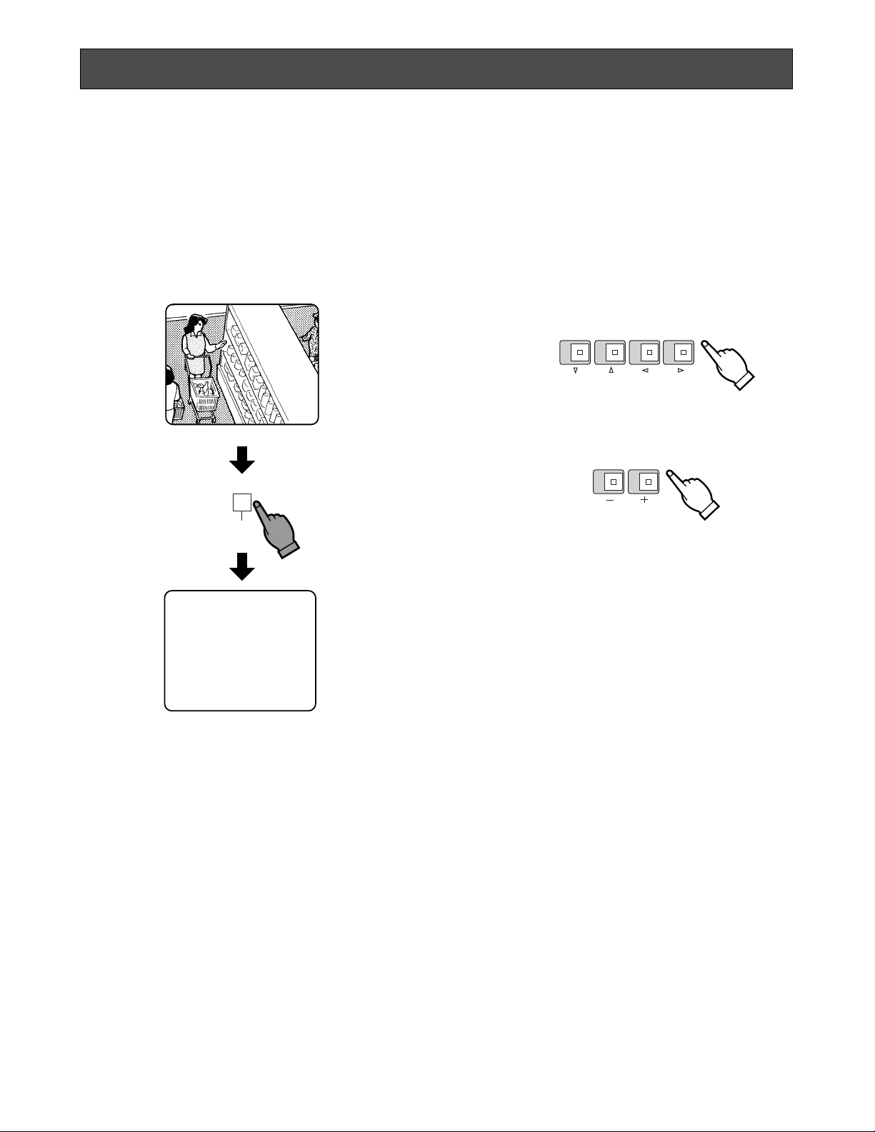
■ Monitoring the Camera Picture
A. Full Size Single Picture
1. Confirm the current mode is neither the SEQ, PLAY,
EL-ZOOM, nor STILL mode. If the current mode is
any mode above, reset the current selected mode.
2. Press the desired VIDEO SELECT button. The
selected camera picture appears on the monitor
screen.
ENTRANCE
Camera Picture
OPERATION
Page 18

-16-
B. Multi Picture
Note: To display the multi screen, the setting of the VTR
OUT menu is required. See page 8 for details.
1. Confirm the current mode is neither the SEQ, PLAY,
EL-ZOOM, nor STILL mode. If the current mode is
any mode above, reset the current selected mode.
2. Press the MULTISCREEN button to select the
QUAD-A, QUAD-B, or 3x3.
The multiscreen changes each time you press the
MULTISCREEN button as follows when all parameters on the VTR OUT menu are ON.
The channel assignment is as shown in the following
diagrams at factory setting. You can change the
assignment by setting the CH SETUP menu. See
page 14 for details.
12
34
QUAD-A
12
34
QUAD-B
3 x 3
123
456
789
The LEDs on the VIDEO SELECT buttons light to
indicate the channels now displayed on the monitor
screen.
Notes:
• Some frames are skipped as the picture segments are displayed.
• Multi pictures being monitored may sometimes
vibrate vertically, but this does not indicate a
malfunction.
• When 3x3 is displayed on the monitor screen
with factory setting, no picture is assigned for
the 9th channel. To assign the channel, see “3-7
CH SETUP” on page 14 for details.
• Quad Shift
When you monitor the quad picture, the quad picture will be switched to another quad picture by
pressing the QUAD SHIFT button.
12
34
56
78
(QUAD-A)
(QUAD-B)
Page 19

-17-
Example of Full Picture Pattern Sequences.
1 CH
4A (QUAD-A)
8 CH
3 x 3
4B (QUAD-B)
4A (QUAD-A)
3 CH
2 CH
D. Quad Picture Sequences
Notes:
• The setting of the VTR OUT menu is required in
advance. See page 8 for details.
• The setting of the SEQ SETUP menu is required in
advance. See page 12 for details.
1. Press the MULTISCREEN button to display the quad
picture.
2. Select the SEQ mode (indicator lights) by pressing
the MODE button.
3. Press the SET button. The SEQ indicator goes off
and the PLAY indicator lights, then the QUAD-A and
QUAD-B are displayed alternatively with the dwell
time you set on the SEQ SETUP menu.
Camera 1
Picture
Camera 2
Picture
Camera 5
Picture
Camera 6
Picture
Example of quad picture sequence
Camera 3
Picture
Camera 4
Picture
Camera 7
Picture
Camera 8
Picture
QUAD-A
QUAD-B
Note: When 3x3 picture is displayed, this mode is
not available.
C. Full Picture Pattern Sequences
Notes:
• The setting of the SEQ SETUP menu is required in
advance. See page 12 for details.
• To display the multiscreen in this mode, the setting
of the VTR OUT menu is required. See page 8 for
details.
• See page 19 about recording pictures in this mode.
1. Press one of the VIDEO SELECT buttons to display
the full size single picture.
2. Select the SEQ mode (indicator lights) by pressing
the MODE button.
3. Press the SET button. The SEQ indicator goes off
and the PLAY indicator lights, then the picture is displayed in the sequential order with the dwell time
you set on the SEQ SETUP menu.
** VTR OUT **
QUAD A ON
QUAD B ON
3x3 ON
** SEQ SETUP **
FULL SEQ QUAD SEQ
1: 1CH 1: 4A 2SEC
2: 4A 2: 4B 2SEC
3: 8CH
4: 3x3
5: 2CH
6: 3CH
7: 4A
8: 4B
9: OFF
10: OFF
Page 20

-18-
Normal Camera Picture
ENTRANCE
Still Picture
(The word "STILL" blinks)
STILL?
STILL?
STILL
E. Still Multi Picture
This function is available for multiscreen camera
picture only.
1. Confirm the current mode is neither the PLAY, ELZOOM nor STILL mode. If the current mode is any
mode above, reset the current selected mode.
2. Display the multiscreen on the monitor screen.
3. Select the STILL mode by pressing the MODE button.
4. After confirming the STILL indicator is lit, press the
SET button.
5. Press the desired VIDEO SELECT button. The
selected picture appears still on the monitor screen.
Notes:
• If you press the VIDEO SELECT button for a
camera whose picture is not displayed on the
monitor screen, the operation is ignored.
• The word “STILL?” appears only when ON is
selected for STILL-SEL TITLE on the SYSTEM
SETUP menu.
• During the STILL mode is activating, setting the
SEQ or PLAY mode switches to the STILL mode
to the SEQ mode.
• When the alarm signal is received the STILL
mode is canceled automatically.
• When the camera title is displayed, the word
“STILL” and the camera title appear alternatively
on the monitor screen.
• The word “STILL” appears only when ON is
selected for STILL TITLE on the TITLE SETUP
menu.
Page 21

-19-
■ Monitoring the Playback Picture
A. Playback Picture
1. Confirm the current mode is the PLAY mode. If the
current mode is any other mode, reset the current
selected mode and select and set the PLAY mode.
The word “PLAY” appears on the monitor screen.
2. Operate the VTR.
Notes:
• Zoomed picture is available for playback picture. See “B. Zoomed Playback Picture” below.
• The word “PLAY” appears only when ON is
selected for PLAY TITLE on the SYSTEM SETUP
menu.
When the SEQ mode is selected, the order of the pictures to be recorded changes as follows if you assigned
QUAD-A, QUAD-B, or 3x3 in the sequential order of
FULL SEQ (setting of the VTR OUT menu is required):
When the Single or Multi picture is selected
When two or three parameters of the VTR OUT menu
are ON, the pictures are recorded as following example.
In case the VTR OUT menu is set as below:
** VTR OUT **
QUAD A ON
QUAD B OFF
3x3 ON
** VTR OUT **
QUAD A ON
QUAD B ON
3x3 ON
** SEQ SETUP **
FULL SEQ QUAD SEQ
1: 1CH 1: 4A 2SEC
2: 2CH 2: 4B 2SEC
3: 3CH
4: 4CH
5: 4A
6: 3x3
7: OFF
8: OFF
9: OFF
10: OFF
When the SEQ mode is selected
Even though you set all parameters of the VTR OUT
menu are ON, unassigned multi picture in order of FULL
SEQ is not recorded. See following example:
In case the VTR OUT menu and the SEQ SETUP menu
setting are as below:
Full Size Spot
QUAD-A
QUAD-A
QUAD-A
QUAD-A
3 x 3 3 x 3
Full Size Spot
Pictures to be recorded
on the VTR
QUAD-A is selected.
3 x 3 is selected.
Full size spot picture
is selected.
Pictures to be monitored
on the screen
Full size spot picture is selected
after power is turned on.
1CH
2CH
QUAD-AQUAD-A
QUAD-A
3 x 3 3 x 3
3 x 3
Pictures to be recorded
on the VTR
QUAD-A and 3x3
are recorded
alternatively.
Pictures to be monitored
on the screen
Page 22

-20-
B. Zoomed Playback Picture
To zoom the playback picture, setting of the ZOOM
POSITION parameter on the ZOOM SETUP menu is
required. The operation procedure is different according to the ZOOM POSITION parameter. See page 9 for
setting.
In case of QUADRANT is selected for ZOOM POSITION
1. Confirm the current mode is the PLAY mode. If the
current mode is any other mode, reset the current
selected mode and select and set the PLAY mode.
2. Select the EL-ZOOM mode by pressing the MODE
button.
3. After confirming the EL-ZOOM indicator is lit, press
the SET button.
4. Press the desired VIDEO SELECT (1, 2, 3, or 4) button. The selected area is zoomed twofold. Each
VIDEO SELECT (1, 2, 3, or 4) button selects the following areas.
Note: If you press the VIDEO SELECT button whose
picture is not displayed on the monitor screen,
the operation is ignored.
Quad playback picture
12
34
Zoomed playback picture (Quad)
(In case the button No.2 is pressed)
2
ZOOM
PLAY
PLAY
41 32
Button
No. 1
Button
No. 3
In quad picture
Button
No. 1
Button
No. 3
In 3x3 picture
Button
No. 2
Button
No. 4
Button
No. 2
Button
No. 4
3x3 playback picture
41 32
ZOOM
PLAY
PLAY
Zoomed playback picture (3x3)
(In case the button No.2 is pressed)
Page 23

-21-
In case of VARIABLE is selected for ZOOM
POSITION
1. Confirm the word “PLAY” is displayed on the monitor screen.
2. Select the EL-ZOOM mode by pressing the MODE
button.
3. After confirming the EL-ZOOM indicator is lit, press
the SET button.
The “+” sign and the word “ZOOM” appear on the
monitor screen.
Note: The “+” sign disappears if no operation is
performed within approx. 4 seconds.
4. Press the No.6 (+) button to zoom the picture
twofold.
5. Move the zoomed picture by pressing the CURSOR
(CC, DD, AA, BB) button.
6. To return the picture to the original size, press the
No.5 (–) button.
Page 24

-22-
SYSTEM 1
A system consisting this quad unit and the specified cameras should include the WV-PS104C camera drive unit.
Notes :
• When pressing the ALARM RESET/MULTISCREEN/QUAD SHIFT button or the VIDEO SELECT/CURSOR/SELECT buttons, the picture on the video monitor may roll briefly at the time of switching.
SIGNAL
GND
RS-232CPLAY IN ALARM/REMOTE
(VS1Vp-p)
GENLOCK
IN
VIDEO
OUT
GENLOCK
OUT
VTR
OUT
OUT
IN
765
VIDEO
321
876544321
8
Monitor
Computer
VTR
VTR OUT VIDEO OUT
VIDEO
VIDEO OUT
VIDEO IN
WJ-MS488
CAMERA 5
CAMERA 1CAMERA 4
CAMERA 8
IN
CAMERA
OUT
VIDEO
OUT
AUDIO
4ch
IN
CAMERA
OUT
VIDEO
OUT
AUDIO
3ch
IN
CAMERA
OUT
VIDEO
OUT
AUDIO
2ch
IN
CAMERA
OUT
VIDEO
OUT
AUDIO
1ch
IN
VD/SYNC
OUT
VD/SYNC
(4Vp-p 75Ω)
CAUTION
VIDEO
WV-PS104C
SYSTEM CONNECTIONS
Page 25

-23-
SYSTEM 2
The input video signals for this unit are synchronized, and synchronization noise or disturbances in the video output signal
will not occur when the multi or single picture mode is selected.
Connections
• Connect the VIDEO IN connectors of this unit to the video output connectors of the cameras.
• Connect the VTR OUT connector of this unit to the video input connector of the video distribution amplifier (V.D.A).
• Connect the output of the video distribution amplifier (V.D.A.) to the video input connector of the VTR and to the genlock input connectors of the cameras.
• Connect the VIDEO OUT connector of this unit to the video input connector of the monitor.
SIGNAL
GND
RS-232CPLAY IN ALARM/REMOTE
(VS1Vp-p)
GENLOCK
IN
VIDEO
OUT
GENLOCK
OUT
VTR
OUT
OUT
IN
765
VIDEO
321
876544321
8
Monitor
Monitor
VTR
VDA
VIDEO VIDEO
VIDEO
VIDEO
WJ-MS488
GENLOCK
GENLOCK
GENLOCK GENLOCK
VIDEO
VIDEO
VIDEO
VIDEO
GENLOCK
GENLOCK
GENLOCK GENLOCK
Page 26

-24-
SYSTEM 3
Connections
• Connect the VIDEO IN connectors of this unit to the video output connectors of the cameras.
• Connect the VTR OUT connector of this unit to the input connector of the VTR.
• Connect the VIDEO OUT connector of this unit to the input connector of the monitor.
• Connect the wires of the alarm sensors to the alarm input pins of ALARM/REMOTE connector.
SIGNAL
GND
RS-232CPLAY IN ALARM/REMOTE
(VS1Vp-p)
GENLOCK
IN
VIDEO
OUT
GENLOCK
OUT
VTR
OUT
OUT
IN
765
VIDEO
321
876544321
8
WJ-MS488
Monitor
Monitor
VTR
Sensor Sensor Sensor Sensor
Sensor Sensor SensorSensor
Page 27

-25-
Buzzer
NO
C
NC
To Buzzer
Relay
+24V
NC: Normally Closed Contact
NO: Normally Open Contact
C: Common
• Connection with the Alarm Output Connector
Power capacity of alarm output connector less than
100 mA:
• Make sure to match the polarity when connecting the buzzer to the alarm output connector.
• Connect the positive pole (+) of the buzzer to
pin 11 of the alarm output connector.
Power capacity of alarm output connector more than
100 mA:
• Connect the buzzer through a relay circuit to pin
11 of the alarm output connector. Do not connect it directly.
• Remote Control
You can control the SEQUENCE, PLAY, EL-ZOOM, STILL mode, and the MULTISCREEN/QUAD SHIFT, VIDEO SELECT,
and MENU/ESC buttons from a remote controller. Connect ALARM/REMOTE Connector (pin 5) to the ground terminal.
These functions are activated by contact with the ground terminal. The assignment of each pin is as follows.
13251224112310229218207196185174163152141
Ground
Ground
ALARM/REMOTE (CH5)
ALARM/REMOTE (CH6)
ALARM/REMOTE (CH7)
ALARM/REMOTE (CH8)
Ground
Alarm Out
Play back
Alarm Reset Out
Alarm Recover In
ALARM/REMOTE (CH2)
ALARM/REMOTE (CH1)
ALARM/REMOTE (CH3)
ALARM/REMOTE (CH4)
ALARM/REMOTE Select
MENU/ESC
Multiscreen Select
Ground
Still
Sequence
Zoom
Ground
Page 28

-26-
BLOCK DIAGRAM
This unit is consisted as below.
When the multi picture is displayed, the same multi picture is recorded at that moment. See “Monitoring the Playback
Picture” on page 19 about differences of recording way.
TL TL
VTRVTR
WJ-MS488
DIGITAL BLOCK
Video Monitor
Single spot or single sequence
Selected in Setup menu
VTR
OUT
EL-ZOOM
STILL
QUAD A
QUAD B
3 x 3
1 to 8
Analog
Select
VIDEO
OUT
Up to 8 cameras
PLAY
IN
CAMERA
IN
Page 29

m=0 Still OFF
m=1 Still ON
nn=00
All video channels specify
nn=01 - 08 Camera Number
Item
OZM
Item
-27-
Parameter (ASCII)Response Command (ASCII)Command (ASCII)
OCS : mm
OST : m : nn OST
VTR/Camera Select OVC : m OVC
m=0
Camera Mode
m=1 VTR Mode
Still ON/OFF
Multiscreen / Quad
Shift
OTC : m OTC
m=0
QUAD-A I : Increment
*1
m=1 QUAD-B D : Decrement
*1
m=2 3 x 3
Sequence OSQ : m OSQ
m=0
End Sequence
m=1 Activate Sequence
Electronic Zoom
ON/OFF
OZM : m : nn
m=0 Zoom OFF nn=01 - 04
*2
m=1 Zoom ON
Full Size Single CH
Select
OCS mm=01 - 08 Camera Number
Alarm Reset OAL : m OAL
m=0
Manual Reset
m=1 Auto Reset
APPENDIX
The values for the RS232C site communication setting of this unit are as follows.
Baud Rate: 9 600
Parity Bit: Odd
Data Bit: 8 bit
Stop Bit: 1 bit
Note: These values are fixed.
● Communication Protocol
• The data format is shown below.
[STX] [ ] [ ] [ ] [ETX]
ASCII (02H) ( ) ( ) ( ) (03H)
● Command T able
A transmission command consists of 3 alphanumeric characters following an address. If a command requires a parameter,
add a colon (:) after the command. If it needs a second, insert a colon (:) between them.
If a command with a parameter has no parameter value specified, it will be processed at the underlined parameter value.
Note:
• When remote controlling this unit by computer through the RS232C port, add the unit address to the transmission com-
mand.
For example,
ADuu; OCS: mm (uu=01 - 04 unit number)
(1) Main Unit Operation Control
(2) Mode Change
Command (ASCII) Response Command (ASCII) Parameter (ASCII)
Setup MSU : m MSU
m=0
End Setup
m=1 Begin Setup
*1: Selecting "I" shifts pictures as: QUAD-A → QUAD-B → 3 x 3
Selecting "D" shifts pictures as: 3 x 3 → QUAD-A → QUAD-B
*2: 01-04 indicate area number.
Page 30

Item
-28-
mm=UU Move Upward
mm=DD Move Downward
mm=RR Move to Right
mm=LL Move to Left
mm=ES Previous Directory
(ESC)
mm=IC Select parameter (+)
mm=DC Select parameter (–)
*3
DCR : mm DCR
(3) Cursor
Command (ASCII) Response Command (ASCII) Parameter (ASCII)
Cursor Movement
Select Parameter
*3 The parameter valid on the main unit setup menu is:
mm=UU, DD, RR, LL, ES,IC, DC
The parameter valid for zoom position move during electronic zooming is:
mm=UU, DD, RR, LL
Notes:
• When you operate with the buttons on the front panel before finishing data processing commanded by PC, this unit puts
the operation by the buttons above the operation by PC.
• If commands are sent by PC continuously, transmission error occurs infrequently. When it occurs and commands are
not executed, send the unexecuted commands again.
Page 31

-29-
Video Input : 2:1 interlace, composite 1 V [p-p] 75 Ω, auto termination or loop-through, black and white or
colour video signal x 8 (Each video signal should be synchronized vertically for vertical inter-
val switching. Does not have to be synchronized in case vertical interval switching is not
required.)
Video Output : Video Output x 1, composite, 1 V [p-p] 75 Ω, colour or black and white video signal with com-
posite sync and burst signal.
Recording Output : 1.0V[p-p]/75 Ω x 1 (BNC)
External Sync Input : VS 1.0V[p-p]/75 Ω/looping through x 1 (BNC)
Playback Input : 2:1 interlaced VBS 1.0V[p-p]/75 Ω/automatic termination/looping through x 1 (BNC)
Title : Up to 8 characters per window
Alarm Input : One per 8 video inputs (max. DC 5 V and make-contact for ground)
Alarm Output : One (max. DC 100 mA, open collector circuit)
Alarm Duration : Adjustable approx. 1s to 30 s, 1, 2, 3, 4, 5 min. or EXT
Recover Input : One (max. DC 5 V and make-contact for ground)
Auto Reset Time : Adjustable approx. 1s to 30s, 1, 2, 3, 4, 5 min. or OFF
Ambient Operating Temperature : −10˚C to +50˚C (14˚F to 122˚F)
Power Source and
Power Consumption: AC 220 - 240 V, 50 Hz, 18 W
Dimensions : 420 (W) x 44 (H) x 350 (D) mm
[16-1/2” (W) x 1-3/4” (H) x 13-3/4” (D)]
Weight : 4.0 kg (8.9 lbs.)
Weight and Dimensions shown above are approximate.
Specifications are subject to change without notice.
SPECIFICATIONS
STANDARD ACCESSORIES
Rack Mounting Brackets ................................................1 set
Rack Mounting Bracket Fixing Screws ..........................8 pcs
Switch Protector .............................................................1 pc
Page 32

N0998-0 YWV8QA4913AN Printed in Japan
N 30
Matsushita Electric Industrial Co., Ltd.
Central P.O. Box 288, Osaka 530-91, Japan
 Loading...