

Page 1

Before attempting to connect or operate this product,
please read these instructions carefully and save this manual for future use.
No model number suffix is shown in this manual.
Admin Console
User's Guide
Model No. WJ-MPU955A
Page 2

The contents of this document are subject to change without notice and do not constitute
a commitment on the part of Matsushita Electric Industrial Co., Ltd. Every effort has
been made to ensure the accuracy of this document. However, due to ongoing product
improvements and revisions, Matsushita Electric Industrial Co., Ltd. cannot guarantee the
accuracy of printed material after the date of publication, nor can it accept responsibility
for errors or omissions. Matsushita Electric Industrial Co., Ltd. will update and revise
this document as needed.
The software and hardware described in this document may be copied or used only in
accordance with the terms of the license pertaining to said software or hardware.
Reproduction, publication, or duplication of this manual, or any part thereof (with an
exception - listed below), in any manner, mechanically, electronically, or
photographically, is prohibited without permission of the Matsushita Electric Industrial
Co., Ltd.
Permission is given to reproduce or duplicate the entire “Worksheets” section at the end
of this manual as needed, and the “Definition” topics within the “Configuration” section.
©2001 - 2006 by Matsushita Electric Industrial Co., Ltd.
All rights reserved.
Trademarks
Microsoft and Windows are registered trademarks of Microsoft Corporation in the United
States and other countries.
Intel and Pentium is a registered trademark of Intel Corporation in the United States and
other countries.
Other products and company names mentioned herein may be the trademarks of their
respective owners.
Page 3

Table of Contents
Welcome...............................................................................................................1
Introduction ...........................................................................................................3
Control of the System........................................................................................3
How It Works.....................................................................................................4
Configuration Management ...........................................................................4
User Control...................................................................................................4
What Happens Next ..........................................................................................4
Installation.............................................................................................................5
System Requirements .......................................................................................5
Minimum Hardware Requirements ................................................................5
Minimum Video Display Setting Requirements ..............................................5
Operating System Requirements...................................................................5
Installing MPU955A Admin Console..................................................................6
What Happens Next ..........................................................................................6
Configuration ........................................................................................................7
Worksheet Tasks...............................................................................................7
Instructions........................................................................................................8
Checklist............................................................................................................8
Starting the Program .........................................................................................9
Logging In .........................................................................................................9
First Time Operation........................................................................................10
CPU Setup...................................................................................................10
Scheduled Modes ........................................................................................ 13
Main Window................................................................................................... 15
Database Management ...................................................................................16
At Installation ...............................................................................................16
Database Archive ........................................................................................16
Creating a Database....................................................................................17
Selecting a Database...................................................................................18
Renaming a Database .................................................................................20
Deleting a Database .................................................................................... 21
Backing up or Restoring a Database ........................................................... 22
CPU System File .........................................................................................28
Resetting the Main CPU ..............................................................................35
Shutting Down the Main CPU ......................................................................36
Redundant CPU Control ..............................................................................37
Configuring a System ......................................................................................40
Overview...................................................................................................... 40
Switch Nodes...............................................................................................41
GX Digital Nodes .........................................................................................41
SX850 – Matrix Frames ...............................................................................44
SX650 – Switch Nodes ................................................................................47
Components ................................................................................................50
Alarms .........................................................................................................51
Cameras ......................................................................................................63
System Controllers ......................................................................................73
i
Page 4

Table of Contents
Digital Recorders .........................................................................................77
Viewing and Programming Modes ............................................................... 82
Controllers Recorder Tab.............................................................................83
Adding or Removing Cameras for a Defined Recorder................................85
Alarm Input/Output.......................................................................................87
Monitors.......................................................................................................90
Operators..................................................................................................... 96
Automate.......................................................................................................104
Tour Sequences ........................................................................................105
Group Presets............................................................................................111
Group Sequences......................................................................................117
Event Scheduler ........................................................................................123
Tools .............................................................................................................126
Log Manager..............................................................................................127
AC Log....................................................................................................... 132
Areas .........................................................................................................134
Account Manager.......................................................................................136
Help ...........................................................................................................139
Uninstalling .......................................................................................................139
Appendix A .......................................................................................................140
Appendix B .......................................................................................................150
Glossary............................................................................................................151
Acronyms ......................................................................................................151
Terms ............................................................................................................ 152
General Index ...................................................................................................157
Worksheets.......................................................................................................161
Instructions....................................................................................................161
Teamwork .....................................................................................................162
Checklist........................................................................................................ 162
ii
Page 5

Welcome
Welcome
Welcome to the MPU955A
guide is organized in a logical step-by-step sequence that will allow for both an easy and
accurate configuration.
First, an explanation of what MPU955A Admin Console is and how it works in a
Network Security System (NSS) is presented in general terms. Next, you will be guided
through installing the software, creating a configuration database, and loading the
database into the Network Security System’s CPU.
While creating the configuration database, you will find that many components interact
with each other, and are dependent on specific values. It will be important to utilize the
worksheets provided at the end of this manual to gather the data necessary to create the
configuration database, and to develop an understanding of your Network Security
System. These worksheets, once completed, should also be utilized when making
updates or changes to the system’s configuration, to ensure accurate results.
This part of the process will be explained in the Configuration section of this manual,
which is divided into three phases: physical planning, worksheet tasks, and keying in the
data.
*
Admin Console Installation and Configuration manual. This
*
Throughout this document, MPU955A refers to WJ-MPU955A.
1
Page 6

This page intentionally left blank.
2
Page 7

Introduction
Introduction
MPU955A Admin Console enables an administrator and other users to closely control the
operation of a Network Security System (NSS). Such a system can include as many as
1,024 cameras and 256 monitors. You will be guided through the process of installing
MPU955A Admin Console to manage an NSS, creating the databases that dictate the
operation of the NSS, and allowing an administrator to easily change the system’s
configuration when necessary.
Control of the System
MPU955A Admin Console enables an administrator to utilize an NSS’s performance
capabilities to meet the surveillance needs of a facility during initial installation, as well
as when conditions change.
The NSS can be configured to help security personnel respond in different ways using
MPU955A Admin Console. For example, based on:
• Time of day - such as when open to the public, closed, and after-hours cleaning
and maintenance.
• Night quiet time.
• Quiet day of the week - which would be a 24-hour period of quiet time without
any activity except security personnel doing rounds.
• Special business activity - such as taking physical inventory, restocking, and
doing routine maintenance of special equipment.
• Visits by celebrities, dignitaries, or officials.
In addition, the NSS can be configured using MPU955A Admin Console to allow for
quick responses to unexpected disruptions of normal activity that could be caused by
power, fire, police, health, or other emergencies.
3
Page 8

Introduction
How It Works
MPU955A Admin Console is a management tool that maintains tracking, reporting, and
functional relationships between the various components in a network security system.
Configuration Management
It is possible for MPU955A Admin Console to maintain several separate configurations
for a given system.
One configuration, for example, could differ greatly from the typical configuration used,
because its purpose may be to watch over a particular activity, such as the taking of an
equipment and supplies inventory when the facility is closed to the public.
User Control
In addition to controlling individual cameras, MPU955A Admin Console provides the
user with selections from lists of presets and sequences.
• If the user chooses a group preset, a group of monitors will display a set of video
outputs from a group of cameras at preset positions.
• A sequence, on the other hand, is a system-controlled series of views - one of
several cameras on one monitor (a Tour Sequence) or of group presets (a Group
Sequence on several monitors).
What Happens Next
Installing the MPU955A Admin Console software only takes a few minutes and is very
simple to complete. A series of Windows dialog boxes guide the installation onto the PC.
The subsequent task of configuring the software, once installed, can range from modest,
for a small system, to complex, for a very large system, such as in an airport.
When it comes to security surveillance, all potential contingencies should be considered
when planning a system’s functionality. MPU955A Admin Console is the tool that
simplifies this process.
4
Page 9

Installation
Installation
Part of installing MPU955A Admin Console means copying program files from a CDROM onto the hard drive of a dedicated PC. MPU955A Admin Console is a tool that
allows an administrator to configure the NSS (Network Security System) with
information compiled about components and users, and to use well-planned presets and
sequences.
System Requirements
As with any PC application that must be reliable, MPU955A Admin Console should be
the primary program running on the computer it is installed on. There should be little
other than MPU955A Admin Console running on the same computer.
Minimum Hardware Requirements
• PC with an Intel® Pentium
• 64 MB memory
• 20 MB free hard drive space
• 10/100 Mbps Ethernet network interface card
Minimum Video Display Setting Requirements
• 256 colors
• 800 x 600 resolution
Operating System Requirements
• Microsoft
2000 Professional SP4, XP Professional SP2
®
Windows® (English Version)
®
III processor
5
Page 10

Installation
Installing MPU955A Admin Console
1. Insert the MPU955A CD-ROM into the CD-ROM drive on your computer – an
installation menu will appear
2. Select Admin Console and click the Next button – MPU955A Admin Console
will begin installing automatically
3. Respond to the dialog boxes by following the directions given
What Happens Next
The next section will guide you through the phases involved with the setup and
configuration of a MPU955A System, using the Admin Console.
6
Page 11

Configuration
Configuration
MPU955A Admin Console configuration is a three-step process:
1. Mark copies of drawings of the facility under surveillance.
2. Fill in the appropriate worksheets provided at the end of this manual. (This will
result in a survey of all the components in your system, and how they interact
with one another.)
3. Enter the values collected on the worksheets into MPU955A Admin Console.
(The values entered determine the operation of the Network Security System
(NSS) in complete detail by creating relationships among all of the components,
including the users.)
Once existing copies of the facility’s drawings are marked, there is a basis for assigning
logical or area/local numbers, titles, and practical names for the various components of
the surveillance system. With this information, you can then continue with the
MPU955A Admin Console worksheet tasks indicated below.
Worksheet Tasks
The MPU955A Admin Console worksheets aid in the collection and organization of
information needed to configure the NSS. One person can complete all of the worksheets
in a smaller system, but to speed up any installation, consider assigning a team of several
individuals to complete different worksheets concurrently.
Perhaps the surveillance system you are working with is small enough for you to collect
the required information, and input those values directly on to the MPU955A Admin
Console screens.
However, if the system is more complex, it is best to gather and write down the
information needed for the initial configuration of MPU955A Admin Console.
If settings need to be modified or updated in the future because of a change in
surveillance needs, or changes made in the components of the system, the worksheets can
be used to track past, current, and future configurations. The worksheets make it very
easy to do this, regardless of the size of your system.
7
Page 12

Configuration
As with any system configuration, it is wise to keep initial and updated worksheets on file,
just in case there is ever a need to re-enter the data, or troubleshoot the system.
Instructions
The title of each worksheet is the same as the title of the MPU955A Admin Console
window it supports. For example, the “Operators” worksheet supports the “Operators”
window. The fields that need to be filled in on the various MPU955A Admin Console
windows correspond to the sequence presented on the worksheets.
Reproduce the worksheets supplied with the system.
Copy pages from the actual worksheets located in the back of this manual.
You may only need a single copy of a certain worksheet, but dozens of copies of others,
depending on the number of components that make up your surveillance system.
Checklist
Worksheets are arranged alphabetically to make them easy to find. However, you can
follow the checklist below vertically for a workable sequence.
For a team approach to information collection, use best judgment to decide how to
distribute the worksheet among several individuals.
CPU Setup
Node Definition
(GX, SX850, SX650)
Camera Definition
System Controllers
Monitor Definition
Operator Definition
Digital Recorder
Definition(s)
Alarm Input/Output
Tour Sequences
Camera Presets
Group Presets
Group Sequences
Alarm Target
Definition(s)
Alarm Definition(s)
Alarm Target Assignment(s)
Camera-to-Monitor Permission(s)
Controller-to-Camera View Permission(s)
Controller-to-Camera Control Permission(s)
Controller-to-Monitor Permission(s)
Controller-to-Group Sequence Permission(s)
Controller-to-Alarm IO Permission(s)
Controller-to-Alarm Permission(s)
Controller-to-Alarm Permission(s)
Controller-to-Alarm Permission(s)
Controller-to-Digital Recorder Permission(s)
Operator-to-Controller Permissions
Event Scheduler
8
Page 13
Configuration
Starting the Program
To start MPU955A Admin Console:
1. On the taskbar, click the Start button, click on Programs, click on Panasonic,
and then click MPU955A Admin Console
Logging In
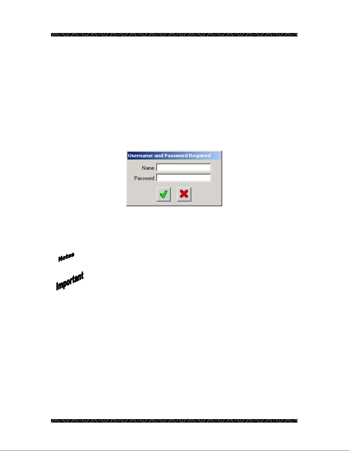
Each time MPU955A Admin Console is run, this login screen will appear.
1. Enter the user login name (default = admin) and click the green check mark
(or press ENTER on your computer’s keyboard)
By default, there is no password defined.
Both the user login name and password fields are case sensitive.
It is recommended that after entering MPU955A Admin Console the first
time, that the admin user login password is changed, in order to control
administrative access.
During the configuration, add user names and passwords at various access levels as
needed. See the Account Manager section on page 136.
9
Page 14
Configuration
First Time Operation
CPU Setup
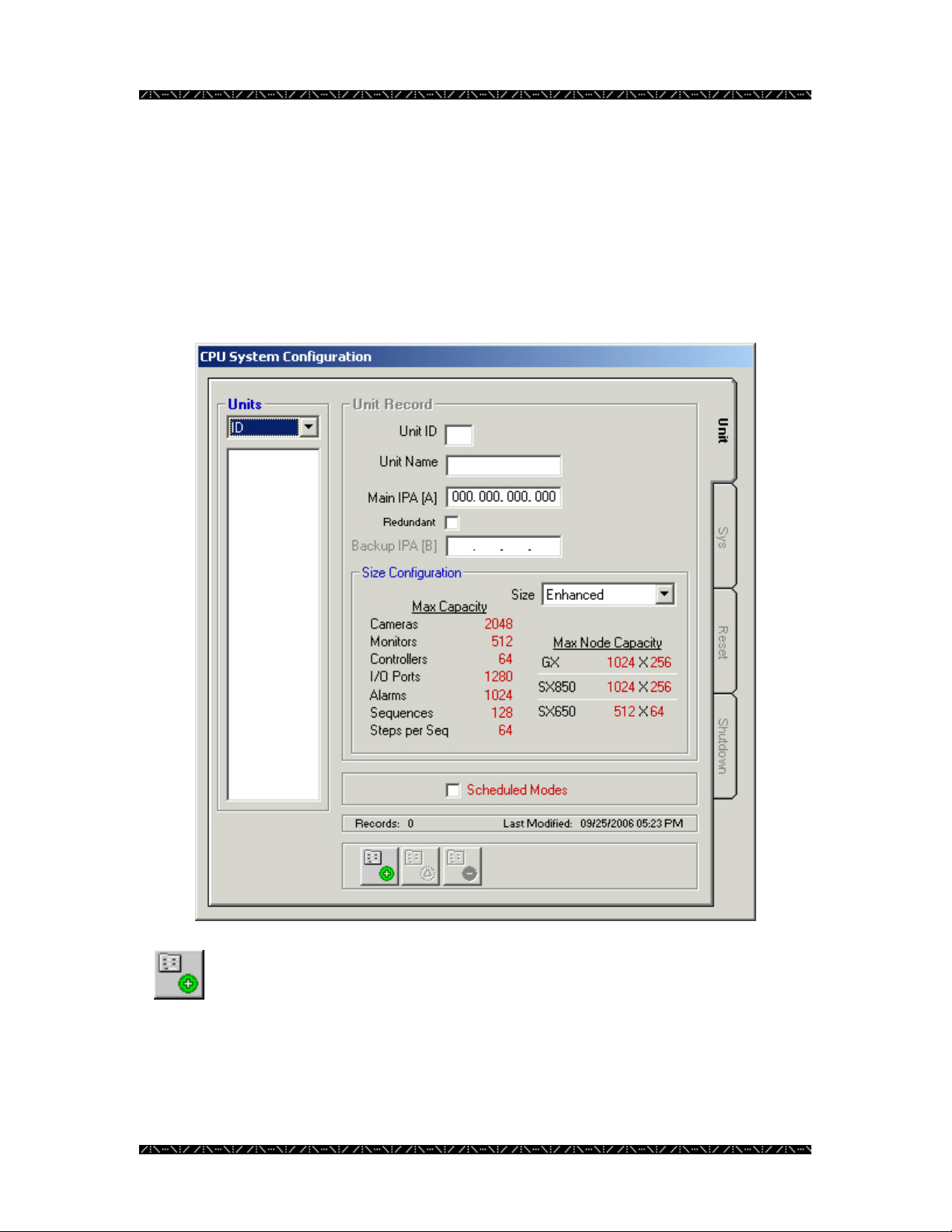
When MPU955A Admin Console is run the first time, the following window will appear
after you enter the default login name.
1. Click the Add Record button
10
Page 15
Configuration
2. Enter a Unit Number for the system unit
Unit ID automatically begins with “1”, however any two-digit number may be entered.
Several separate units may be configured with a single MPU955A Admin Console,
however, Admin Console must be upgraded in order for those units to be linked together.
The unit number must match the number in the CPU System File, which resides on the
actual CPU, with the IP address that will be entered below. Contact your installer or
network administrator for more information on the CPU System File.
3. Enter a Unit Name for the system unit
It is best if the name is practical, and easy to understand by anyone using the system.
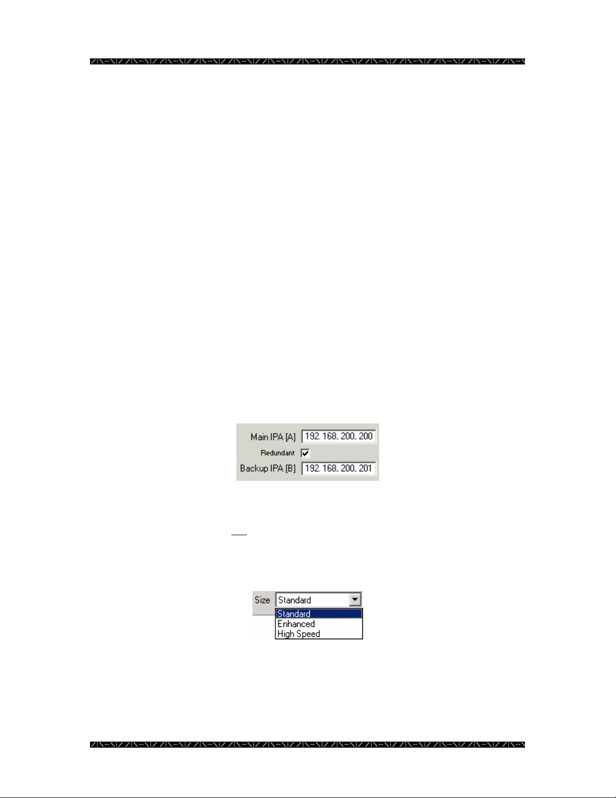
4. Enter the IP address for the Main A CPU
Ask your installer or network administrator for the IP address for the Main A CPU. This
will let the MPU955A Admin Console software know where to send the configuration
database later.
5. If your system is equipped with a redundant CPU, then select the Redundant
check box and enter the IP address for the Main B CPU
Ask your installer or network administrator for the IP address for the Main B CPU. If the
system has just a single CPU, leave the redundant check box blank. In that case, the
Main B CPU IP address will not
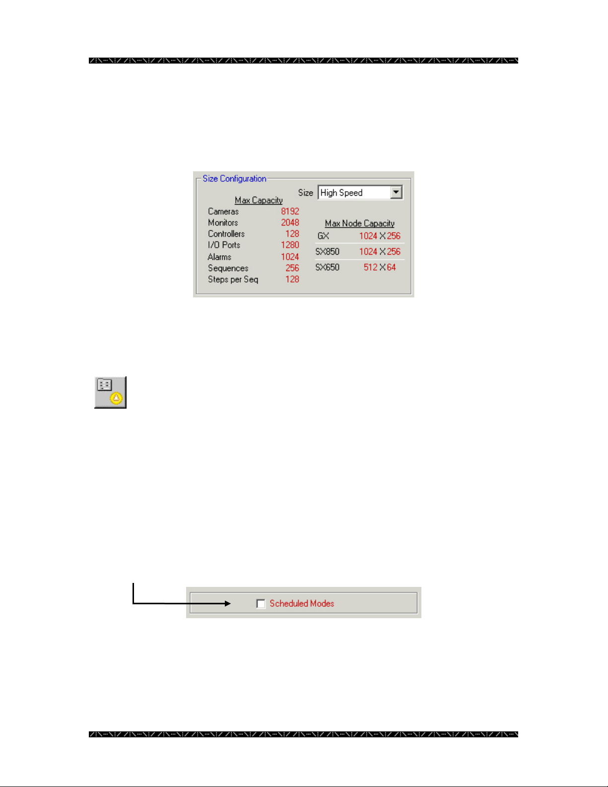
6. Choose the configuration size for the NSS CPU from the Size drop-down
menu
The Size Configuration section of this window is where you will see the details on the
size the CPU you select. As you choose Standard, Enhanced, or High-Speed, from the
Size drop-down menu, the maximum capacities of each size will display. The maximum
capacity is the largest supported number of each of the components listed. You must
match the actual CPU Unit capacity with the capacity in this window.
be required.
11
Page 16
Configuration
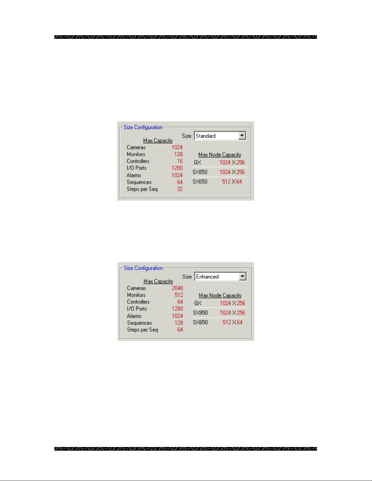
Standard
If any of the components in your system exceed the maximum capacity listed, you must
choose the next highest system type. For example, if the number of each of your
system’s components are less than the maximums listed for “Standard”, but you have 129
monitors, you would need to select “Enhanced” as your system type.
Enhanced
This is the next NSS CPU type available. Using the Enhanced CPU type will increase
the capacity of the system. This can be chosen as long as your system MPU is the correct
version for this type.
12
Page 17
Configuration
High-Speed
This is the largest CPU type available, providing the capacity for handling the largest
number of components.
5. After making your selection, click the green check mark to save.
6. You can then enter the information for another unit, or click the red “X” to
exit the Add mode
7. If an error has been made, click the Edit Record button and make
your changes
8. Click on the EXIT button to leave this window
Scheduled Modes
If the Scheduled Modes check box is selected on the CPU System Configuration
window’s Unit tab, an administrator can configure up to four different modes of
operation that can then be scheduled to become active as desired. The configuration of
these modes are programmed or set by an administrator during the configuration of the
system’s components through MPU955A Admin Console.
13
Page 18
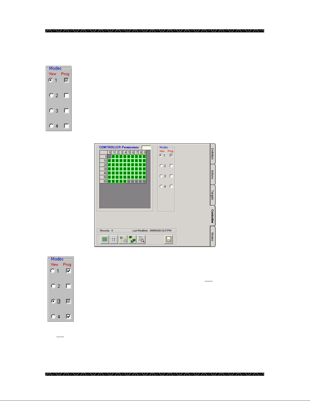
Viewing and Programming
In each of the components’ permissions tabs that contain a section like the
one shown to the left, modes can be viewed and programmed.
Clicking the View option button allows you to view permissions for the
mode chosen, and defaults to programming for the same mode. In the
case of the graphic to the left, mode 1 is set for viewing, and thereby
programming.
The permissions grid reflects the contents of the mode whose view is
selected with the View option button. In the image below, the permission
grid is displaying the contents of mode 1.
Configuration
More than one mode can be programmed at the same time by clicking on
the Prog check boxes of the other mode numbers that you wish to
program simultaneously. This will append, or add any permissions that
are then changed on the permissions grid, but will not
modes or overwrite existing permissions in the other modes.
The image to the left indicates that the permissions grid would now be
displaying the contents of mode 3 (which is also by default being
programmed), and would simultaneously be programming any subsequent
changes into modes 1 and 4 as well.
It is not necessary to perform a Save for each mode viewed or programmed. Saving
permissions, when completed, automatically saves all four modes, regardless of the
current View or Prog selection. Permissions are described on page 67.
14
duplicate entire
Page 19
Configuration
Main Window
After entering the CPU number, IP address, CPU name, selecting your system’s size, and
exiting, the following window will appear, which is the MPU955A Admin Console main
window. This window will be the first one you see from now on whenever you enter
MPU955A Admin Console.
The main window is the heart of the MPU955A Admin Console configuration software.
Each component, sequence, setup, and management task will be accessed from the menus
on this window.
Each section will be utilized in order to configure and maintain the NSS.
15
Page 20
Configuration
py
p
Database Management
The active database for this system is the one residing within the Network Security
System (NSS). MPU955A Admin Console is used to create that database initially, and
from that point forward works with copies of it in order to establish and maintain useful
variations.
At Installation
When MPU955A Admin Console is first installed, an administrator must create and name
a new database. The database is stored on the MPU955A Admin Console computer’s
hard drive.
The administrator then enters all the information available about devices, components,
users, and sequences, and saves these details into the database using the Database
Manager.
See Creating a Database on page 17 for initial and subsequent database creations.
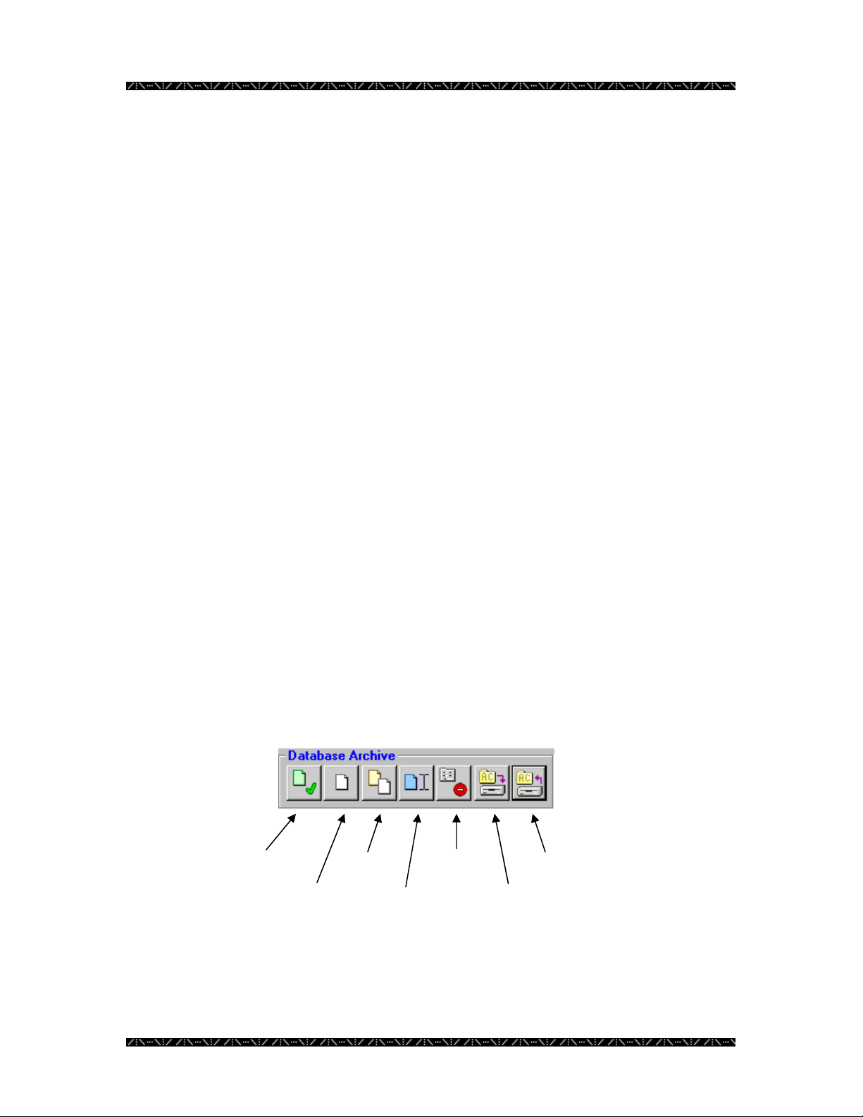
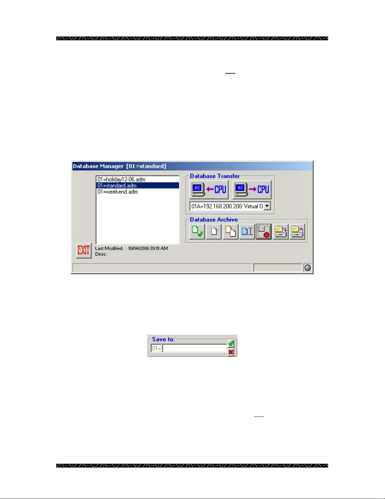
Database Archive
The Database Archive section of the Database Manager window is where each
configuration file (database) is manipulated. Several functions that can be performed
with the configuration files are selecting, creating, copying, renaming, or deleting.
This section also includes options to backup or restore a configuration file to or from
removable media or an alternate location, such as a floppy diskette or network drive.
Select
New
Co
Rename
Delete
Backu
Restore
16
Page 21
Configuration
Creating a Database
When entering Database Manager for the first time, there will not
as none have yet been created. An administrator must create and name a new database
for configuration.
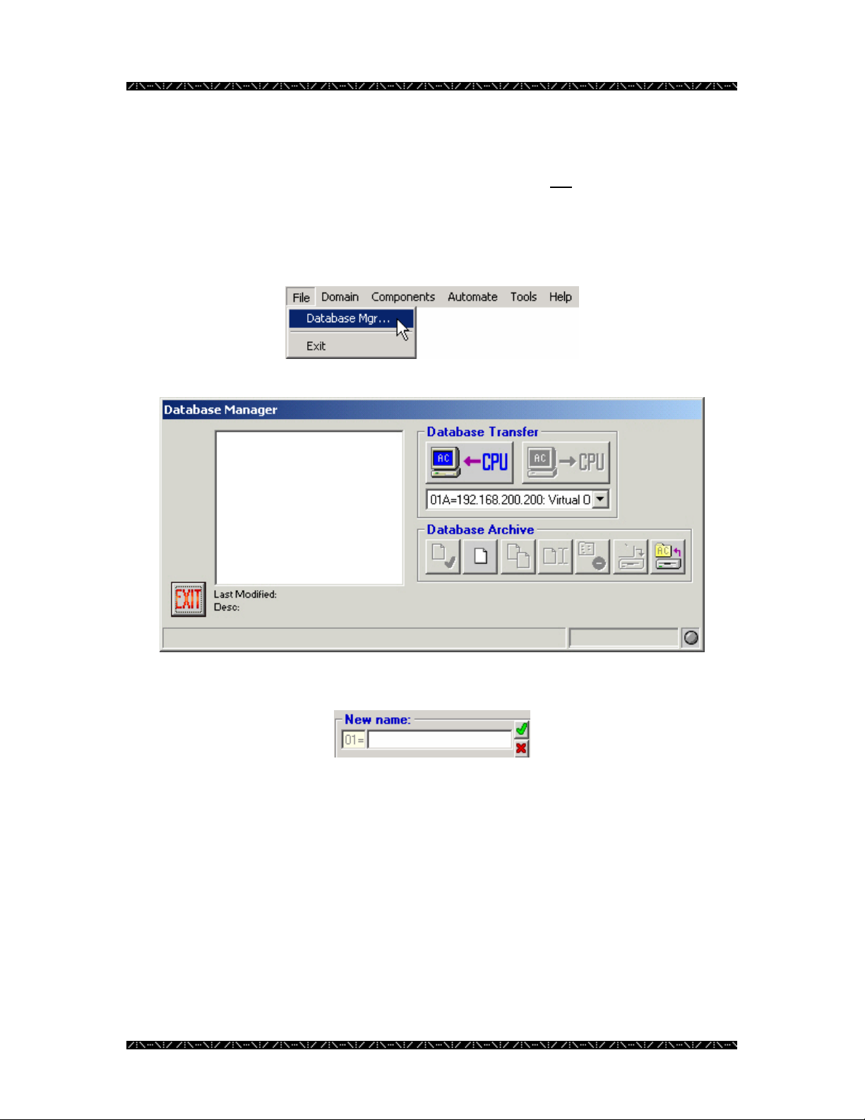
1. Select Database Manager from the File menu
be any .adm files listed,
2. Click on the “New” button – the 2nd button in the Database Archive section
3. Type in a new name for the new database in this field
4. Click the green check mark
Enter any name that fits in the space provided. It is best if the name is practical, and easy
to understand by anyone using the system. You will be returned to the main menu after
naming the database.
This database will reside in MPU955A Admin Console. Adding and saving information
about the components and desired operation of the system will configure it.
17
Page 22
Configuration
Selecting a Database
Viewing and Reconfiguring
Whenever you wish to view or edit settings from the components, sequences, or setup
choices on the main menu, you must have the database, whose contents you wish to work
with, selected. If you have just entered MPU955A Admin Console, and click on one of
those options, you will automatically be prompted to select a database. The database you
choose will open, and will immediately be followed by the option window you have
chosen. The database you select becomes the default database for all settings until you
go back to Database Manager to choose or create a different one.
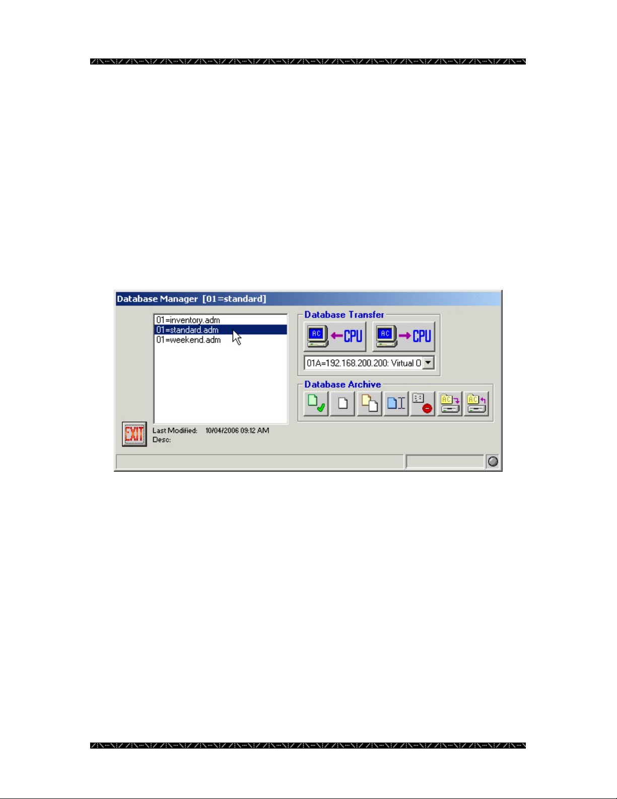
1. Select the name of a database by clicking on it
2. Click the Select button - the button with the green check mark - or double-
click on the desired database
You will notice that the system unit ID number and the name of the database currently in
use are displayed on the title bar of this window. In the example above, the system unit
number is 01, and the database currently being used is “standard”.
When changing the database you are working with, MPU955A Admin Console will open
the selected database, making it the default, and will close the Database Manager window.
You will be returned to the main menu, ready for the configuration or review of the
database you just selected.
18
Page 23
Configuration
Copying a Database
Making Similar or Alternative Databases
An administrator can make copies of a database, as desired, and name them to reflect
their purpose. This would normally be done to enable the system to respond to changing
conditions and surveillance needs without having to completely recreate a database to
accommodate these changes.
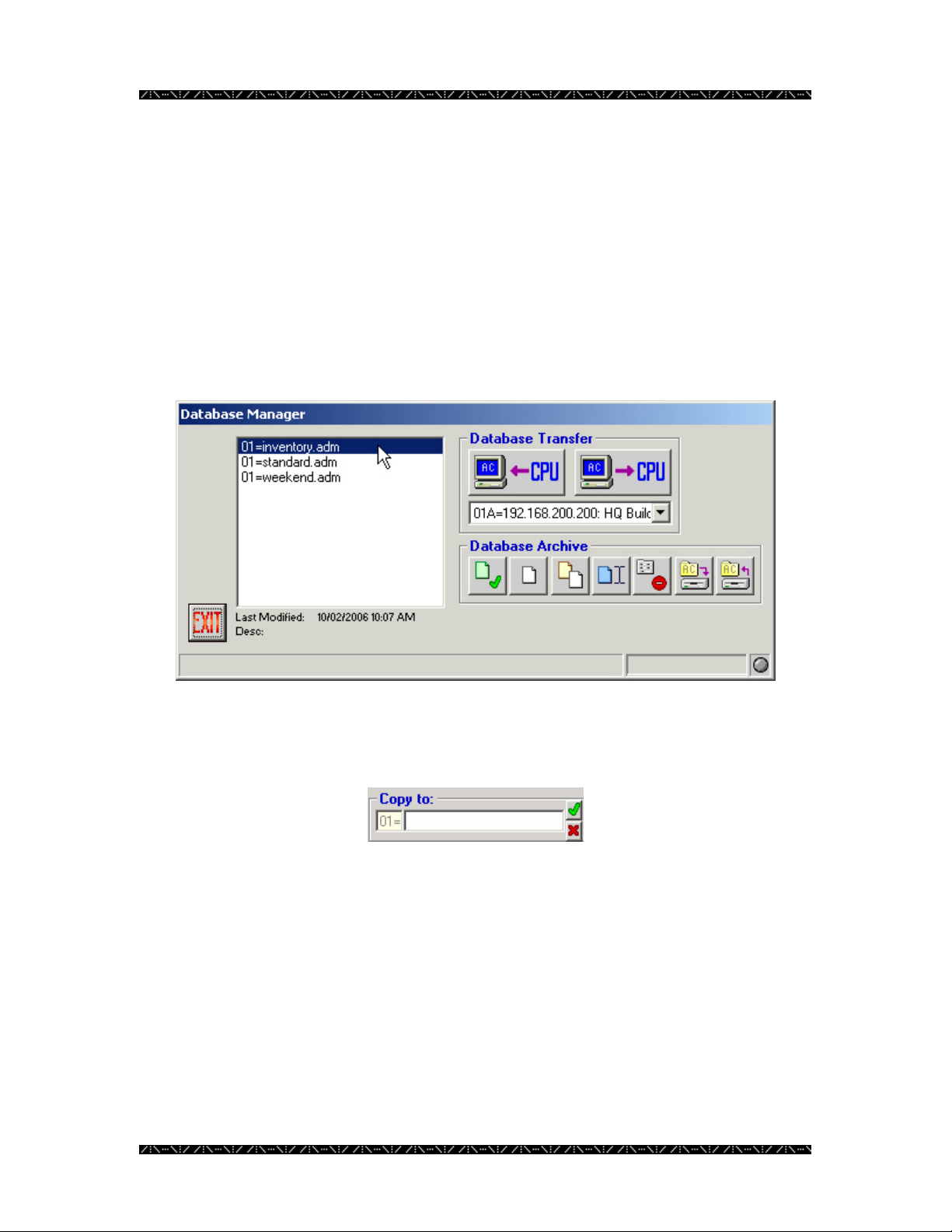
1. Highlight the name of the database you wish to copy in the Database
Manager window
2. Click the Copy button - the button with the yellow and white sheets displayed
3. Name the new copy in the space provided
4. Click the green check mark
Enter any name that fits the space provided. It is best if the name is practical and easy to
understand by anyone using the system.
19
Page 24
Configuration
Renaming a Database
Renaming a database is useful when creating several configurations to fit the needs of
specific occasions, and changing the name to ensure each file has been updated. For
example, if date codes or initials are used in the name or description of a database, an
administrator may want to revise the date code or user initials as necessary.
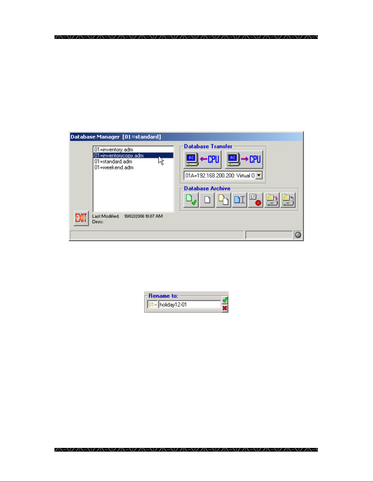
1. To rename a database, highlight a database name
2. Click the Rename button - the button with the blue sheet and cursor
displayed
3. In the “Rename to:” box, type the new name desired
4. Click the green check mark
20
Page 25
Configuration
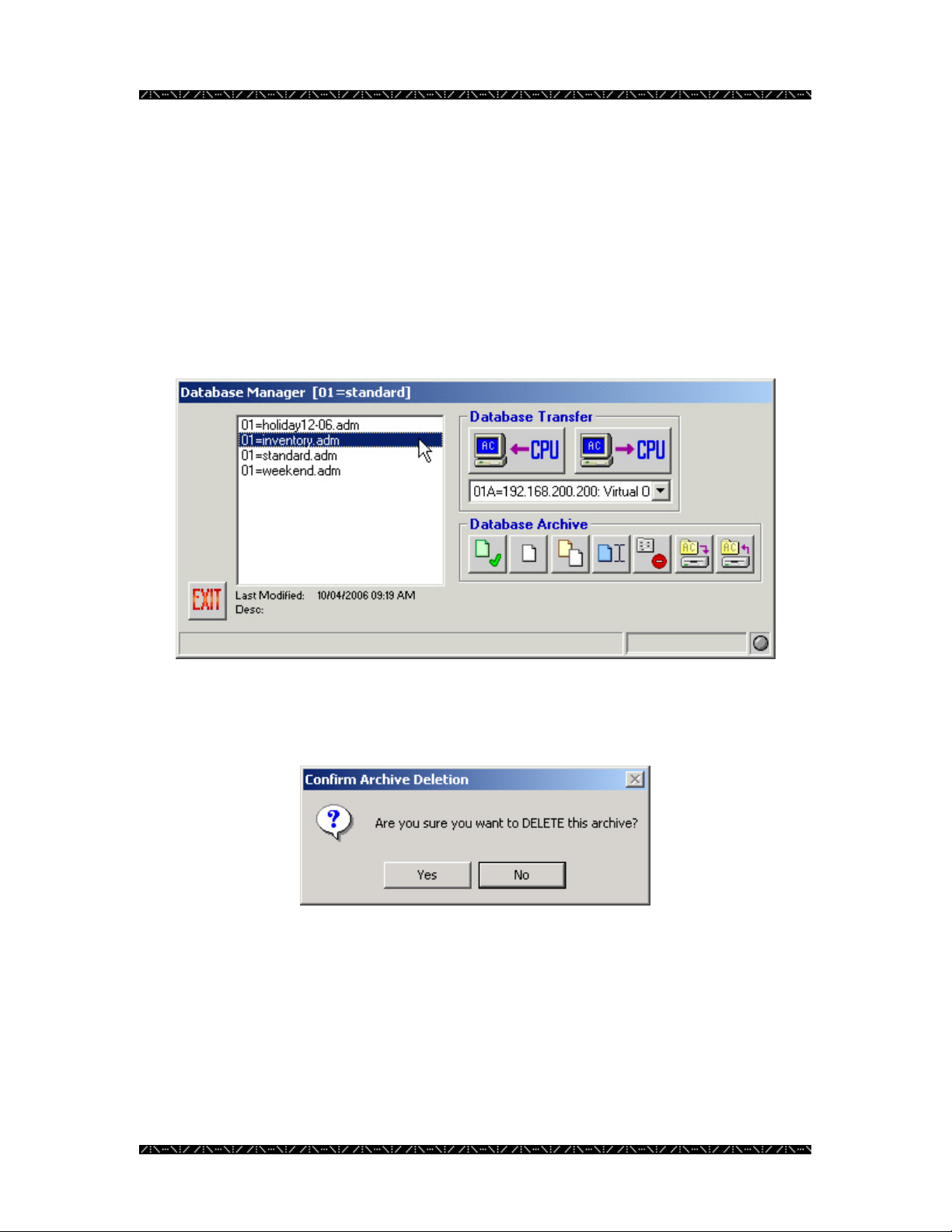
Deleting a Database
In order to reduce the number of configuration files listed in Database Manager, and
thereby decrease the potential for confusion as to which file is loaded on the NSS CPU,
outdated or unused configuration files can be deleted. If the files may be needed again in
the future, it is recommended that you backup the files to an alternate location (see page
22) so they can be deleted from MPU955A Admin Console, and restored later if
necessary.
1. To delete a database, highlight the database name
2. Click the Delete button - the button with the red “X” displayed
The following confirmation message will appear:
3. Click Yes to delete, or No to cancel.
21
Page 26
Configuration
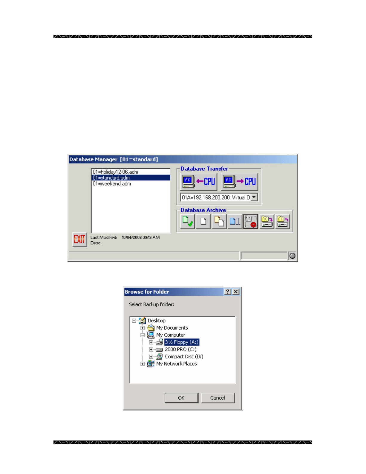
Backing up or Restoring a Database
It may be necessary at times to save a copy of a particular database for backup,
troubleshooting, or other purposes. MPU955A Admin Console allows an administrator
to perform both backup and restore functions in order to maintain copies of the
configuration files outside of the MPU955A Admin Console system.
Backing up a Database
1. Within Database Manager, highlight a database name and click the Backup
button – the button 6
th
from the left in the Database Archive section
The following window will appear.
22
Page 27
Configuration
2. Choose the drive and folder you wish to backup to, just as you would in
Windows Explorer
3. Click OK
This procedure will only copy the highlighted configuration file to the specified location.
It will not remove it from the Database Manager.
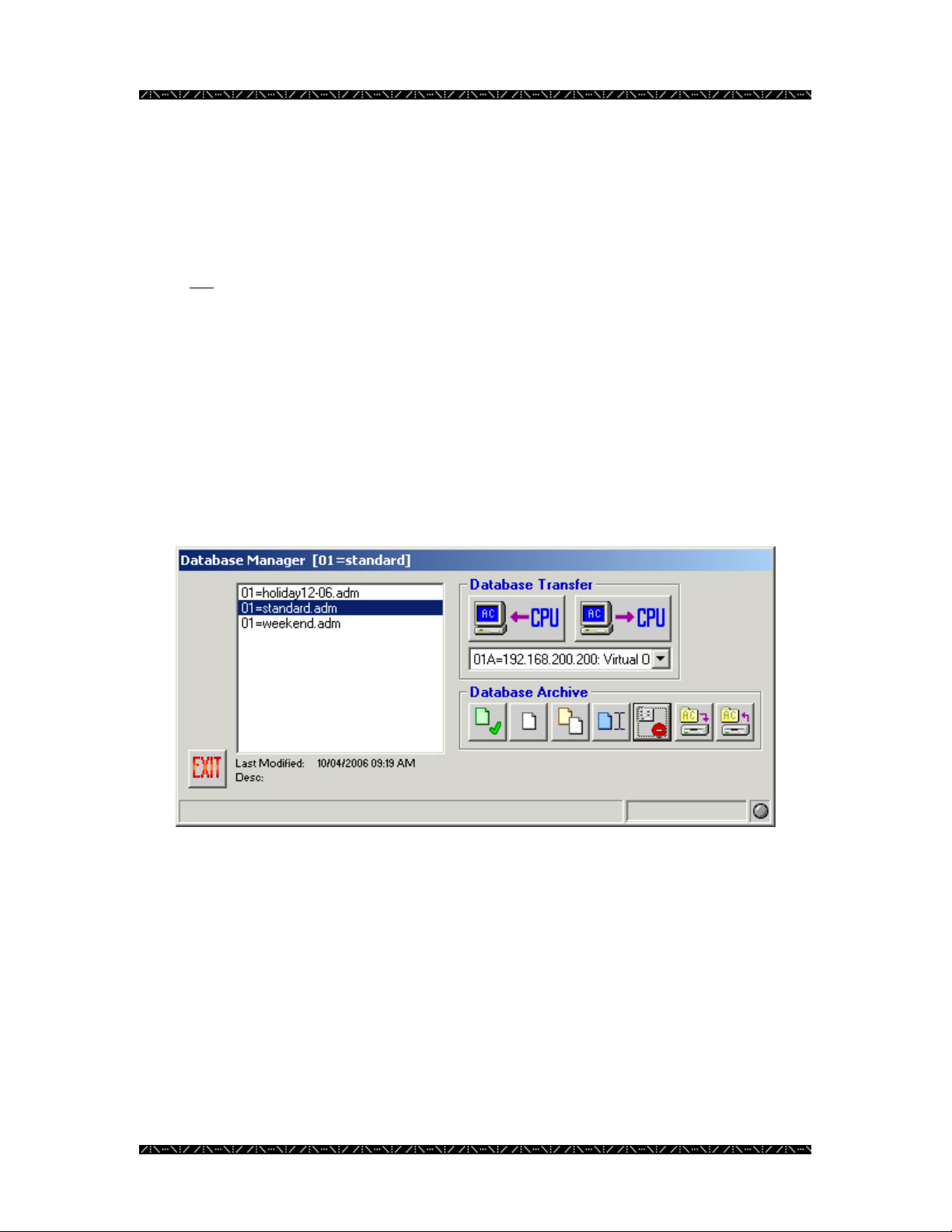
Restoring a Database
In addition to backing up a configuration file, it may also be necessary at times to restore
a copy of a particular database from a backup, an e-mail, or from troubleshooting
personnel. MPU955A Admin Console allows an administrator to perform a database
restore from a source outside of MPU955A Admin Console.
1. Within Database Manager, click the Restore button - the last button from the
left under the Database Archive section
The following window will appear.
23
Page 28
Configuration
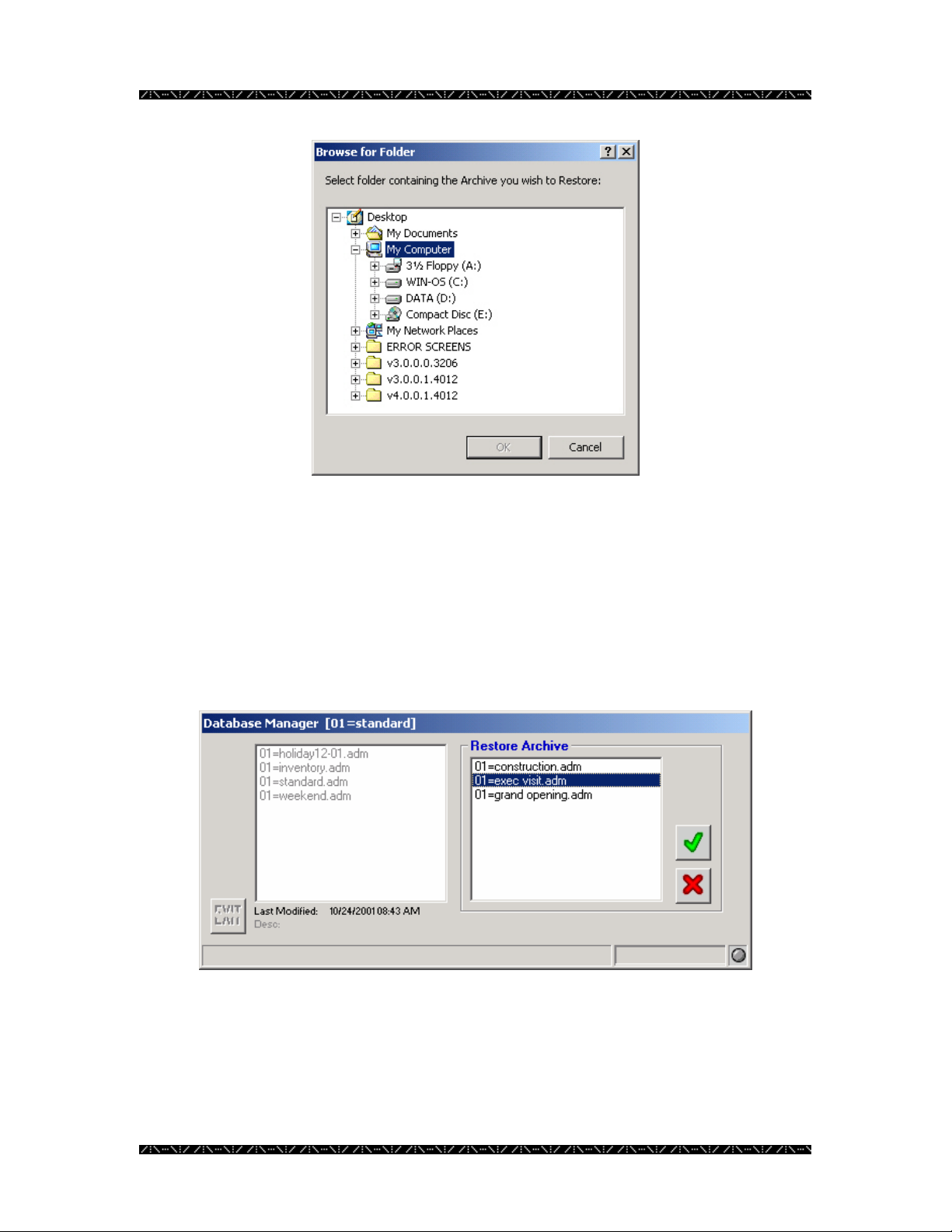
2. Choose the drive and folder that contains the desired .adm file, just as you
would in Windows Explorer
3. Click OK
Because you may have multiple files saved in the same location, the restore feature
allows you to choose which file to restore.
4. Select the desired file to restore, and click the green check mark
The left side of the Database Manager window represents the configuration files already
stored within MPU955A Admin Console. The right side of the window represents the
files stored in the folder that you have just specified.
24
Page 29
Configuration
This procedure will copy the selected configuration file into MPU955A Admin Console
from removable media or an alternate location, but will not remove it from its current
location.
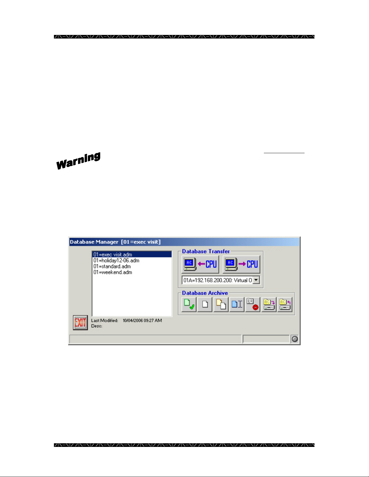
Getting the Current Database
In order to retrieve a copy of the configuration currently running on the system, and to
bring it into MPU955A Admin Console, an administrator must retrieve it using the
Database Transfer section’s “GET from CPU” option. This option allows the
administrator to view, modify, copy, or create new versions of the current configuration
once it is imported into MPU955A Admin Console.
1. From the drop-down menu in the Database Transfer section select either 01A
or 01B CPU
2. Click the “GET from CPU” button - the left button under the Database
Transfer section
3. Enter the new name for this particular database in the “Save to:” box
4. Click the green check mark
A copy of the database that is currently running on the selected NSS CPU is now saved
on the MPU955A Admin Console computer’s hard drive. It will not
the Main CPU. At this time, you may select the file to view or modify the configuration.
be removed from
25
Page 30
Configuration
Loading a Database
In order to copy a configured database from MPU955A Admin Console onto the NSS
Main CPU, an administrator would need to use the Database Transfer section’s “PUT to
CPU” option.
Although not mandatory, first saving the current database residing on the CPU would
allow for a manual comparison of any differences prior to loading the new database.
MPU955A Admin Console itself cannot detect differences. (Unless this is a first time
operation.)
PUTting a configuration database onto the NSS CPU will overwrite its
entire existing database. It is recommended that you GET and save the
database currently running on the Main CPU under a distinctive name
before loading a new database.
The following instruction will guide you through loading a database from MPU955A
Admin Console to the CPU. See the Getting the Current Database section on page 25 to
save the database that is currently loaded in the CPUs.
1. Select the name of the database to load by clicking on the .adm file name
2. From the drop-down menu, select the proper CPU, by number and IP
Address
For a redundant CPU system, you must load the database onto both CPUs to ensure they
are each using the same configuration.
For single CPU systems, choose 01A.
26
Page 31

Configuration
3. Click the “PUT to CPU” button - the right button under the Database
Transfer section
A “Confirm PUT Transfer” window will appear.
If you choose to continue, the new database will be loaded, overwriting the existing
database, and it will remain on the CPU to run the NSS according to the configuration.
4. Click Yes to continue the transfer, or No to cancel
27
Page 32

Configuration
CPU System File
The system file (##A=sys.ini – where ## is the system unit ID number) resides on the
main system CPU, and contains information that is critical for proper operation. On
systems with a redundant CPU, it may be necessary to modify the system file on both of
the NSS CPUs individually, in order to maintain proper operation. DO NOT
file unless instructed to do so by qualified technical support personnel.
MPU955A Admin Console allows an administrator to work with this file. When
instructed, follow the steps below for viewing, modifying, backing up, and restoring the
##A=sys.ini file.
For the purposes of this document, the system unit ID will be 01, so the CPU system file
name will be 01A=sys.ini.
System Transfer
When transferring a system file, the system file is written to the MPU955A Admin
Console computer’s hard drive as “01A=sys.ini” and “01B=sys.ini” - depending on
which CPU this function was performed. In most cases, the system file(s) residing on the
MPU955A Admin Console computer’s hard drive will be an exact duplicate(s) of the
file(s) being used on the system’s CPU(s).
It is possible for the file on the local drive to differ from the one being used by the system,
when using the restore function. An administrator must be very careful when using the
backup and restore functions, as well as when retrieving and replacing the system file on
the CPU(s). It is very important that the administrator be aware of which CPU is being
updated.
Retrieving the System File from the Main CPU
1. Select CPU Units from the Domain menu
modify this
28
Page 33

Configuration
2. Click on the SYS tab on the right side of the window
The following window will appear.
3. Choose “01A” from the SYS Transfer drop-
down menu (01 is the system unit ID in this
example)
4. Click the “GET from CPU” button – the left button under
SYS Transfer
MPU955A Admin Console will retrieve the system file from the selected CPU and
display it in the window provided.
At the same time, the system file is saved in the “\Program
Files\Panasonic\GXLAC\SysIni” folder as “01A=sys.ini” (or “01B=sys.ini” if from the
redundant CPU).
29
Page 34

Configuration
5. Modify the system file as needed
Modifications will not
until a “PUT to CPU” is performed, which replaces the system file in the CPU selected.
See “Replacing the System File in the Main CPU” below, in order to send the updated
file information to the system CPU.
Replacing the System File in the Main CPU
1. From the CPU System Configuration window (accessed by selecting CPU
Units from the Domain menu), click on the SYS tab on the right side of the
window
2. Choose “01A” from the SYS Transfer drop-down menu (01 is the system unit
ID in this example)
This will replace the existing system file in the specified CPU with the modified one.
4. A “Confirm PUT Transfer” window will appear. Click Yes to continue with
the transfer, or No to cancel the transfer
Repeat the steps for Main B CPU, as needed, selecting “01B” from the drop-down menu
in step 2 of the Retrieving the System File from the Main CPU and Replacing the System
File from the Main CPU procedures. (01 is the system unit ID in this example)
It will be necessary to reboot each CPU when finished so that the updated
information is read and executed correctly. See Resetting the Main CPU on
page 35.
be saved on the MPU955A Admin Console computer’s hard drive
3. Click the “PUT to CPU” button – the right button under
SYS Transfer
01A and 01B system files differ slightly. It is not
identical system files be loaded into both Main A and Main B CPUs.
Your system administrator should be consulted when files are changed.
recommended that
30
Page 35

Configuration
System Archive
After the Main A and Main B CPU system files have been
retrieved for the first time, it will be possible to view these files
at a later date without actually performing a transfer. These files
(“01A=sys.ini” and “01B=sys.ini”) will be stored in the
“\Program Files\Panasonic\GXLAC\SysIni” folder on the
MPU955A Admin Console computer’s hard drive.
Selecting
In order to view the system file stored on the MPU955A Admin Console computer’s hard
drive:
1. From the CPU System Configuration window (accessed by selecting CPU
Units from the Domain menu), click on the SYS tab on the right side of the
window
2. Choose “01A” from the SYS Archive drop-down menu
3. Click the “Select” button
31
Page 36

Configuration
Backing Up
After the “01A” and “01B” CPU system files have been retrieved for the first time, it will
be possible to save these files to a different location, such as to floppy diskette. These
files (01A=sys.ini and 01B=sys.ini) are stored in the “\Program
Files\Panasonic\GXLAC\SysIni” folder on the MPU955A Admin Console computer’s
hard drive. Performing a backup from the SYS Archive section will save a copy of the
specified system file to an alternate location of your choice.
1. Choose “01A” from the SYS Archive drop-down menu
2. Click the Backup button under the SYS Archive section
3. When the “Browse for Folder” window appears, browse to the desired
location
4. Click the OK button
5. Repeat for the “01B” system file if needed
Restoring
At some time, it may be necessary to restore or replace the current system files with a
saved (backed up) version, for example, during system troubleshooting. The restore
function will copy the “01A=sys.ini” and “01B=sys.ini” files from the location you
specify, and put them into the “\Program Files\Panasonic\GXLAC\SysIni” directory on
the MPU955A Admin Console computer’s hard drive.
1. Choose “01A” from the SYS Archive drop-down menu
2. Click the Restore button under the SYS Archive section
3. When the “Browse for Folder” window appears, browse to the location that
the saved system file resides
This should be the location you backed the file up to.
4. Click the OK button
The system file (01A=sys.ini) that is stored in the “\Program
Files\Panasonic\GXLAC\SysIni” folder will be replaced with the file from the location
that you specified.
32
Page 37

Configuration
5. Load the restored file into the Main A CPU if desired
See “Replacing the System File in the Main CPU” section on page 30
6. Repeat for the “01B” system file, if needed
Wizard
When you want to make changes to the system file’s [System] section - which defines the
values for Cameras, Monitors, and Keyboards - you can use the wizard function in the
SYS Archive section of the CPU Configuration Window to do this automatically.
If the values for these components already exist in your system file, they will be edited, if
necessary, to reflect the recommended settings. If the values for these components do not
already exist in your system file, the wizard will add them to the system file.
1. Choose “01A” from the SYS Transfer drop-down menu
2. Click the Wizard button under the SYS Archive section.
3. When the Confirm window opens for you to confirm the changes to be made,
click Yes to continue and edit the file, or click No to cancel the wizard
function
33
Page 38

Configuration
The Wizard button’s appearance will change to indicate if any changes to the system file
are recommended. The gauge area on the left side of this icon indicates if the [System]
components’ settings are: A) too low for the CPU size selected (yellow), B) matching the
CPU size selected (yellow and green), or C) too high for the CPU size selected (yellow,
green, and red).
Too low
for CPU
setting
Matches
CPU
setting
Too high
for CPU
setting
When the icon displays yellow and green, indicating that the settings match the CPU size
selected, there is no action required. If the icon indicates settings are too low or too high,
click the Wizard button to have the settings changed to match your system. You will
then be prompted to confirm that you want the suggested modifications of the CPU
system file to take place.
34
Page 39

Configuration
Resetting the Main CPU
After replacing the system file in the main CPU, each CPU needs to be rebooted so that
the updated information is read and executed correctly (See Replacing the System File in
the Main CPU on page 30).
1. Select CPU Units from the Domain menu, and select the Reset tab
2. Select the CPU you wish to reset from the drop-down box
3. Click the red Reset button to reset the selected CPU
4. Verify that you wish to reset the selected CPU by clicking Yes on the
Confirm Reset window that appears
If a backup CPU is in place, you will be asked to reset that CPU as well. Reset
that CPU as well, so that both CPUs are using the update system file.
35
Page 40

Configuration
Shutting Down the Main CPU
To properly shutdown the main CPU, please, follow the shutdown procedure.
1. Select CPU Units from the Domain menu, and select the Shutdown tab
2. Select the CPU you wish to shutdown from the drop-down box
3. Click the red Shutdown button to shutdown the selected CPU
4. Verify that you wish to shutdown the selected CPU by clicking Yes on the
Confirm Shutdown window that appears
After the shutdown procedure is complete you will be notified that it is safe to
turn the power of selected CPU off.
36
Page 41

Configuration
Redundant CPU Control
When a System Unit includes both a Main CPU and a Backup CPU, it is called a
Redundant System Unit. In this case, one of the CPUs will be running in the Active
mode and will actually be controlling the system operation. The other CPU will be
running in Standby mode and will be following all the system activity in order to take
over system operation, in case the Active CPU fails or otherwise can no longer operate.
Admin Console allows an administrator to find the status of both CPUs and display the
results via the software “lights” on the CPU Unit screen, to the right of the Unit IPA
fields on the Unit tab. The Administrator can also set and switch the status of the CPUs.
The colors of the “lights” have the following meaning:
• White means the status is unknown
• Green means the CPU is in Active mode
• Yellow means the CPU is in Standby mode
• Red means there was an error setting or retrieving CPU Status
This feature is only available when Redundant box is checked in the CPU Units screen,
and an IP Address has been entered for both the Main CPU and the Backup CPU.
37
Page 42

Configuration
Get CPU Status
Follow the steps below to determine the status of both Main and Backup CPUs.
1. Select CPU Units from the Domain menu, and select the Unit tab
2. Click the GET CPU Status button
3. The CPU Status “lights”, to the right of the Main and Backup CPU IPA
boxes, will display the Status by color
If valid status cannot be retrieved from either CPU, the administrator will be
asked to try to correct the status. The default status of Main CPU as Active
and Backup CPU as Standby can be downloaded. A message will appear
asking the administrator if it is desired.
38
Page 43

Configuration
Switching CPU Modes
Once the current status of the Main and Backup CPUs is known, the administrator may
change the Active CPU to Standby and the Standby CPU to active. This might be done
to remove the Active CPU for maintenance, for instance. In this case, The Standby CPU
will become Active in approximately 20 seconds, and the Active CPU will re-boot.
Follow the procedure below to switch the CPU operation Modes.
1. Select the CPU Unit from the Domain menu, and select the Unit tab
2. Click the Switch CPU button to the right of the green and yellow CPU Status
“lights”
3. Observe the CPU Status “lights” change colors appropriately
If valid status cannot be retrieved from the newly made Active CPU, the
administrator will be asked to check CPU operation. The Switch CPU button
will return to a Get CPU Status button so that once CPU operation is corrected,
Status may again be retrieved.
39
Page 44
Configuration
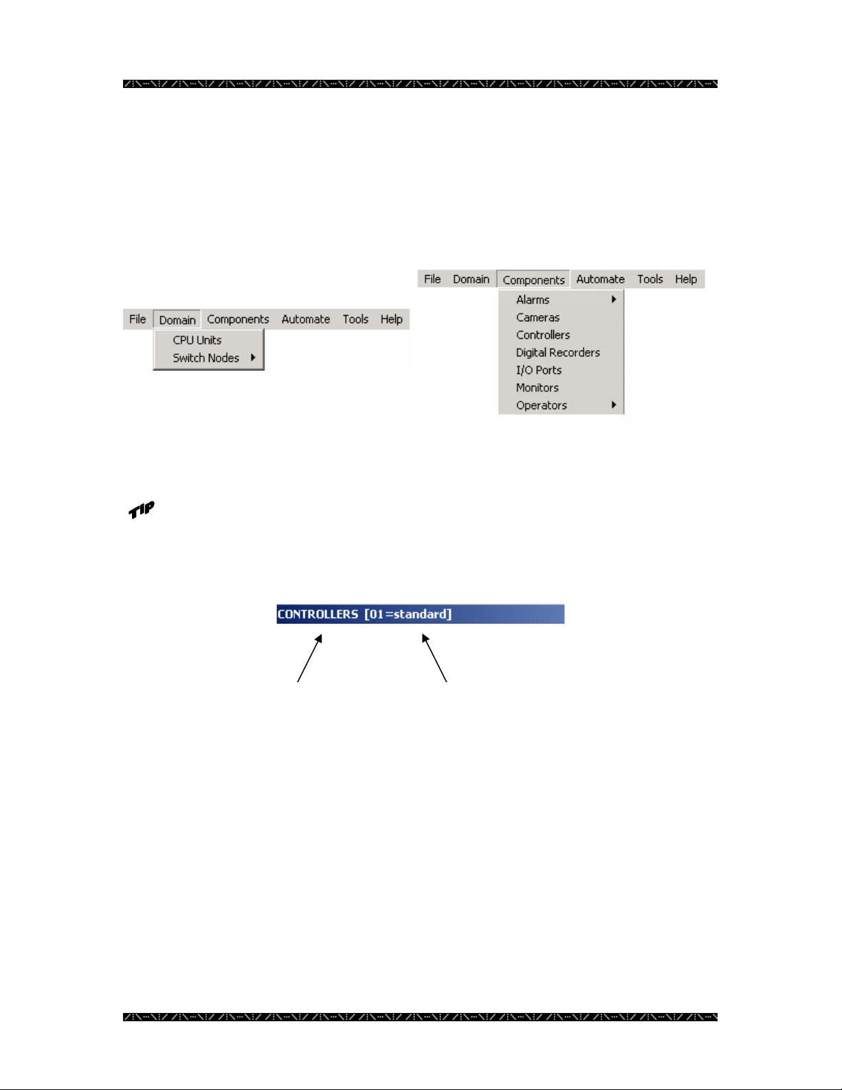
Configuring a System
Overview
You will begin configuring the database using the Domain and Components menus on
the main window:
The title bar of each option window you enter will show the name of the main
menu option being displayed, followed by the name of the current default
database (.adm) file being viewed or edited. In the case below, the option being
displayed is controllers, and the database file being used is standard.adm.
Main menu
option you are
working with.
System unit number, and
database (.adm) file you
are working with.
40
Page 45

Configuration
Switch Nodes
GX Digital Nodes
GX devices include both encoders and decoders. Encoders convert analog video signals
to digital data (MPEG2). Decoders convert digital data (MPEG2) to analog video signals.
Definition
1. Select the Switch Nodes command from the Domain menu, and then select
Digital (GX)
41
Page 46

Configuration
2. Click the Add Record button
3. Enter all information required about each GX Device
GX DEVICES - Definition
Field Data
Unique record ID assigned by MPU955A Admin Console as a device is added, in order to
ID
identify one device to the system. 1 to 1,024.
MPU955A Admin Console automatically generates this number in consecutive order. Upon
adding devices, the system will automatically assign the next available number.
Component ID and sequence ID numbers are used primarily in the permission tabs to identify
one component or sequence from another in row and column style. Since logical and local
numbers are not necessarily unique or consecutive; and the permission grids are displayed as
consecutive, unique numbers; MPU955A Admin Console generates these ID numbers.
Numeric Ethernet interface number identifying a port on a CPU where the device will connect.
I/F
0 to 15, though generally 0, 1, or 2.
Unique Internet Protocol address assigned by the system administrator. Dotted decimal, 15
IPA
characters (including dots). Example: 128.010.050.125
Numeric address for an Ethernet controller. Dotted hexadecimal Example: 23.56.82.13.60.82
EA
(Also known as MAC address.)
A name for the device. Alphanumeric, 16 characters.
Name
Location
Encoder / Decoder
(device type)
A name for the device location. Alphanumeric, 16 characters.
Manufacturer’s serial number. Alphanumeric, 16 characters.
Ser.
If the device is an encoder, select the Encoder button, and choose the range of input ports from
the Input Ports drop-down menu. The range must be unique for each encoder.
For GXDIN, select its Input Ports; for GXDOUT, select its Output Ports; and for GXRS485,
enter its Port number.
Enter the hexadecimal Address [SW1] in the A, B, and C fields.
If the device is a decoder, select the Decoder button, and choose the range of output ports from
the Output Ports drop-down menu. The range must be unique for each decoder.
For GXDOSD Output Ports, select the output ports from the drop-down menu.
Enter the hexadecimal Address [SW1] in the A, B, and C fields.
4. Click the green check mark to save
You will remain in the “Add” mode, allowing you to enter information about another
device.
5. To exit the “Add” mode, click the red X
You will exit the “Add” mode.
6. To edit a configured device, highlight a device ID and click the Edit
button
You may also double-click on a device ID in the list to enter the edit mode.
42
Page 47

Configuration
7. Edit the desired fields
8. Click the green check mark to save and exit the edit mode, or click the red X
to cancel
9. To delete a device, highlight a device ID and click the Delete Record
button
A confirmation message will appear.
10. Click No to cancel, or click Yes to delete the selected device
11. To view details about a device, highlight the device ID and click the
Advanced Config button (see warning below)
A message window appears asking you to confirm that you want to access these settings.
If you answer “Yes”, a GX Details window appears, showing details about the selected
device.
Do not change any of the values in the GX Details table that
appears.
These default settings ensure proper operation in almost all cases.
Refer to the Appendix section of this manual for additional details.
Consult with your surveillance system’s design and
implementation professional before changing any values.
Analog (MX) switch nodes are only configurable in ASC960
Admin Console 4.0. Contact your Panasonic representative for
details.
43
Page 48

Configuration
SX850 – Matrix Frames
Providing local management of the I/O ports they contain, matrix frames communicate
with the system’s main CPU, and allow it to access and utilize the various I/O functions.
Definition
1. Select the Switch Nodes command from the Domain menu, and then select
SX850
Each field preceded by purple text on your computer’s display must be given
a unique number - different from other configured frame records.
44
Page 49

Configuration
2. Click the Add Record button
3. Enter all information required about each Matrix Frame
SX850 MATRIX FRAMES - Definition
Field Data
Unique record ID assigned by Admin Console as a frame is added, in order to identify one frame to the
ID
system. 1 to 1,098.
Admin Console automatically generates this number in consecutive order. Upon adding frames, the
system will automatically assign the next available number.
Component ID and sequence ID numbers are used primarily in the permission tabs to identify one
component or sequence from another in row and column style. Since logical and local numbers are not
necessarily unique or consecutive; and the permission grids are displayed as consecutive, unique
numbers; Admin Console generates these ID numbers.
Numeric Ethernet interface number identifying a port on a CPU where the matrix frame will connect. 0 to
I/F
15, though generally 0, 1, or 2.
Unique Internet Protocol address assigned by the system administrator. Dotted decimal, 15 characters
IPA
(including dots). Example: 128.010.050.125
A name for the matrix frame. Alphanumeric, 16 characters.
Name
The name of the file used by the frame’s booting process. Use the default filename unless instructed to
Boot
do otherwise by qualified personnel. The file name IS case sensitive.
Be sure to check a frame type first, such as controller, OSD, switch, or alarm I/O so that the default frame
boot name will be filled in automatically.
If the boot name field is filled in before the type is selected, the default boot name will not be inserted.
Location
MXCONT
MXOSD
MXSW
MXALM
LCPU Address
A name for the matrix frame location. Alphanumeric, 16 characters.
Manufacturer’s serial number. Alphanumeric, 16 characters.
Ser.
Check 9 if one (or more) WJ-PB85X08 input cards is installed.
If MXCONT (camera control function) is checked, then select range of numbers in Input Ports.
This range will be unique to the entire frame for the controller function, regardless of the number of input
cards installed within the frame.
Check 9 if one (or more) WJ-PB85T0B OSD cards is installed.
If MXOSD (on screen display function) were checked, you would need to select a range of numbers in
Output Ports.
This range will be unique to the entire frame for the OSD function regardless of the number of OSD cards
installed within the frame.
Check 9 if one (or more) WJ-PB85C16 video crosspoint input cards and WJ-PB85M16 video crosspoint
output cards are installed.
If MXSW (switching function) were checked, you would need to select a range of numbers in Input Ports
and Output Ports.
These ranges will be unique to the entire frame for the switching function regardless of the number of
input or output cards installed within the frame.
Check 9 if one (or more) Alarm Input WJ-PB85A32 or Alarm Output WJ-PB85L32 card(s) is installed in
this frame.
If MXALM (alarm I/O function) is checked, then select a range of numbers in I/O Ports.
This range will be unique to the entire frame for the alarm I/O function, regardless of the number of alarm
I/O cards installed within the frame.
Set the matrix frame LCPU identifier on the rotary switches SW12, SW10, and SW9. 0-0-1 to F-F-F.
45
Page 50

Configuration
4. Click the green check mark to save
You will remain in the “Add” mode, allowing you to enter information about another
frame.
5. To exit the “Add” mode, click the red X
You will exit the “Add” mode.
6. To edit a configured frame, highlight a frame ID and click the Edit
button
You may also double-click on a frame ID in the list to enter the edit mode.
7. Edit the desired fields
8. Click the green check mark to save and exit the edit mode, or click the red X
to cancel
9. To delete a frame, highlight a frame ID and click the Delete Record
button
A confirmation message will appear.
10. Click No to cancel, or click Yes to delete the selected frame
46
Page 51

Configuration
SX650 – Switch Nodes
Providing local management of the I/O ports they contain, SX650 Switch Nodes
communicate with the system’s main CPU, and allow it to access and utilize their various
resources.
Definition
1. Select the Switch Nodes command from the Domain menu, and then select
SX650
Each field preceded by purple text on your computer’s display must be given
a unique number - different from other configured frame records.
47
Page 52

Configuration
2. Click the Add Record button
3. Enter all information required about each Switch Node
SX650 Switch Node - Definition
Field Data
Unique record ID assigned by Admin Console as a node is added, in order to identify one node to the
ID
system. 1 to 1,098.
Admin Console automatically generates this number in consecutive order. Upon adding nodes, the
system will automatically assign the next available number.
Since logical and local numbers are not necessarily unique or consecutive, and the permission grids are
displayed as consecutive, unique numbers; Admin Console generates these ID numbers.
Numeric Ethernet interface number identifying a port on a CPU where the matrix frame will connect. 0 to
I/F
15, though generally 0, 1, or 2.
Unique Internet Protocol address assigned by the system administrator. Dotted decimal, 15 characters
IPA
(including dots). Example: 128.010.050.125
A name for the switch node. Alphanumeric, 16 characters.
Name
Location
BRIDGE
CONTROL
SWITCH
ALARM
Node Address
A name for the matrix frame location. Alphanumeric, 16 characters.
Check 9 if this SX650 switch sub-node will be used as a node bridge.
If BRIDGE (system interface function) is checked, then select range of Output Ports.
This range will be unique to the entire system for the bridge function; port range is 1 - 64.
Check 9 if this SX650 sub-node will use camera control function.
If CONTROL (controlling function) is checked, you would need to select a range of numbers in Input
Ports.
This range will be unique to the entire node for the control function based on the number of input cards
installed within the sub-node; input ports are 1 – 1024.
Check 9 if this SX650 sub-node will provide OSD function.
OSD
If OSD (character overlay function) is checked, you would need to select a range of numbers in Output
Ports.
This range will be unique to the entire node for the OSD function based on the number of output cards
installed within the sub-node.
Check 9 if this SX650 sub-node will provide switching function.
If SWITCH (matrix switching function) is checked, then select a range of numbers in Input Ports and
Output Ports.
This range will be unique to the entire system function, based on the number of input and output cards
installed within the sub-node; input port range is 1 – 1024; output port range is 1 - 64.
Check 9 if this SX650 sub-node will provide alarm control.
If ALARM (alarm I/O function) is checked, then select a range of numbers in I/O Ports.
This range will be unique to the entire node for the alarm I/O function, based on the number of output
cards installed within the sub-node.
Set the Node Address to the [MODE] switches of the BRIDGE sub-node. 0 0-0-0 to 1-1-0-1.
Numeric address for an Ethernet controller. This field is only required if MODE switch
EA
Address is not chosen. Dotted hexadecimal Example: 23.56.82.13.60.82 (Also known as MAC
address.) Use all zeroes if not using DHCP.
4. Click the green check mark to save
48
Page 53

Configuration
You will remain in the “Add” mode, allowing you to enter information about another
switch node.
5. To exit the “Add” mode, click the red X
You will exit the “Add” mode.
6. To edit a configured switch node, highlight a frame ID and click the
Edit button
You may also double-click on a frame ID in the list to enter the edit mode.
7. Edit the desired fields
8. Click the green check mark to save and exit the edit mode, or click the red X
to cancel
9. To delete a switch node, highlight a frame ID and click the Delete
Record button
A confirmation message will appear.
10. Click No to cancel, or click Yes to delete the selected switch node
49
Page 54

Configuration
Components
Selecting any of the components listed on the Components menu opens a window that
requires information from one or more of the Setup Worksheets that you have completed.
Input the required information for each of these components separately: alarms, cameras,
system controllers, digital recorders, alarm I/O ports, monitors, and operators.
50
Page 55

Configuration
Alarms
Alarms play an important role within an NSS. Alarms can automatically trigger up to ten
actions, such as camera spots, tour sequences, or group sequences, in any combination.
These actions allow the system to open or close a contact connected to an I/O port that
will start a siren or possibly turn on a spotlight. They also can alert the operator by
displaying cameras on a monitor during a triggered alarm.
In order to configure alarms successfully, an administrator must first create the alarm
targets, and then create records that will initiate the actions. Targets are defined as a
group of monitors. The alarm actions are then linked to available alarm targets.
The following are rules to follow when configuring alarms:
• An alarm can invoke up to ten actions
• A monitor can be a member of only one target
• A target can contain several monitors exclusively
• Many targets can be linked to each alarm
• The same target can be assigned to more than one alarm
Defining an alarm can be a challenging task. ID numbers identify each alarm, source,
action type, and target. The following procedure will explain each step so that an alarm
target can be defined, an alarm can be identified by the source, actions can be taken when
the alarm is triggered, and a target can be defined and assigned to display the specified
action.
51
Page 56

Configuration
Alarm Target
An alarm target is an ID number that defines a group of one or more monitors.
Alarm targets are assigned to alarms in order to link alarm actions to specific monitors.
At least one alarm target must be created before you can create an alarm.
When an alarm is triggered, an action will occur. For example, causing a camera spot
(configured in the alarm definition) to display on an array of monitors assigned to a
specific target.
Be careful when assigning monitors across areas to the same target.
This will be important when assigning a target that contains monitors
in a different area than the Alarm Action Tour Sequence.
1. Select the Alarms command from the Component menu, and then select
Target Setup
52
Page 57

Configuration
2. Click the Add Record button to add a target record
3. Double-click on each monitor ID that you wish to add to this target record
As you double-click on a monitor ID number’s corresponding box, the representative box
will turn green, indicating that it is now part of this record.
First row = monitor IDs 0-9, second row = monitor IDs 10-19, etc.
Besides choosing which monitors will be part of a specific target ID, you must also
choose either Hold or Sequence from the Display Mode section of this window to define
the display mode for the entire target record.
When more than one monitor is selected, alarm actions are distributed across those
monitors.
When “Hold” is chosen, the alarm action with the highest priority for each monitor is
displayed, and remains until it is acknowledged. Once acknowledged, the next queued
action with next-highest priority is then displayed – again until acknowledged. When
“Sequence” is chosen, the alarm actions for each monitor are displayed in sequence
without requiring acknowledgement.
You will also select the first and last Output Port for the entire target record. The First
port indicates which port will be triggered when there is an alarm action to the target
53
Page 58

Configuration
monitor. The Last port indicates which port will be triggered when the alarm actions are
removed from the target monitor.
4. Click the green check mark to add the series of monitors, or click the red X
to cancel
The permission grid is shown by monitor ID only.
A monitor can only be a member of one target. Therefore, when adding
additional targets, monitors that are already assigned to a different target
appear as yellow blocks. Green blocks indicate monitors assigned to the
highlighted target ID. White blocks are either unassigned or undefined
monitor IDs.
To re-assign a monitor to a different target, remove the monitor from its
current target, thus making it available for re-assignment. You can determine
what target ID it is currently assigned to by clicking on it and seeing the ID
number that appears in the Target box under the grid.
Targets cannot be deleted if they are assigned. The assignment must be
removed from the Alarms window prior to deleting it.
The Other tab shows the alarm(s) that the selected target is assigned to. Targets are
assigned to alarms from the Target tab of the Alarms (Records) window as described
below.
Use the Edit Record or Delete Record icons at the bottom of this window to edit or delete
alarm target records as needed.
54
Page 59

Configuration
Alarm Definition
1. To define an alarm record, select Alarms from the Components menu,
2. Then select Records. An Alarm Target must be created before an alarm can be
defined.
3. Add, edit, or delete alarm records as needed using the three icons at the bottom of
this window.
55
Page 60

Alarms – Definition
Field Data
Unique record ID assigned by MPU955A Admin Console as an alarm is added, in order to
ID
identify the alarm to the system.
MPU955A Admin Console automatically generates this number in consecutive order. Upon
adding alarms, the system will automatically assign the next available number.
Component ID and sequence ID numbers are used primarily in the permission tabs to identify one
component or sequence from another in row and column style. Since logical and local numbers
are not necessarily unique or consecutive, and the permission grids must be displayed as
consecutive, unique numbers, MPU955A Admin Console generates these ID numbers. 1 to
1,024.
Logical
Priority
Enable
Auto Arm
Allow Disarm
One State
Output Port:
Active
Source:
Unique number assigned by an NSS administrator. An operator will view alarms by this logical
number. 1 to 99999.
Level that determines an order of precedence between alarms. Alarm priorities work in
conjunction with the operator priority and determine the order of precedence between alarms and
operators. (Smaller number has higher priority) 0 to 65534.
Defines whether or not an alarm is enabled. Check the box to enable the specific alarm.
If checked, the specified alarm will automatically re-arm itself after being acknowledged
If checked, operator will be allowed to disarm the specified alarm.
If checked, the specified alarm, once triggered, will not be monitored for its return from the
triggered state.
This is useful when you are only concerned that the alarm was triggered, but do not need to know
the duration of the triggered state.
An alarm set for One State can be reset even if the alarm condition still exists. Without this
option checked, if an alarm is triggered and you attempt to reset it, it will continuously trigger
again until the triggered state has ended.
If checked, the indicated output port will be turned ON when this alarm is active.
If not checked, the indicated output port will be turned OFF when the alarm is active.
Enter an output port number to specify which port will be turned ON or OFF when the alarm is
active.
If no output port action is required when the alarm is active, uncheck and leave the output port
number blank.
If checked, the indicated output port will be turned ON when this alarm is acknowledged.
Ack
If not checked, the indicated output port will be turned OFF when the alarm is acknowledged.
Enter an output port number to specify which port will be enabled when the alarm is
acknowledged.
If no output port action is required when the alarm is acknowledged, uncheck and leave the
output port number blank.
If checked, the indicated output port will be turned ON when this alarm is reset.
Reset
If not checked, the indicated output port will be turned OFF when the alarm is reset.
Enter an output port number to specify which port will be enabled when the alarm is reset.
If no output port action is required when the alarm is reset, uncheck and leave the output port
number blank.
Type
Identifies the source of the specified alarm, camera (motion detection), or I/O (external source
connected to an alarm input card), RS232 (external source connected to an RS232 port), Vid Loss
(any) (detects video loss from any port in the system), or Vid Loss (cam) (detects video loss only
from the single specified camera).
Configuration
56
Page 61

Alarms – Definition
Field Data
Uniquely identifies the chosen source that will trigger the specified alarm by its ID number.
ID
Camera = port number of camera connected to the controller card. I/O Port = port number of the
Input port that the external source is connected. RS232 = port number of the external source that
will be connected through the RS232 port. Vid Loss (port) = port number of the input port that
will be detecting video loss. Note: When the source type is Vid Loss (any), this selection is
unavailable since multiple ports on the system can serve as the source.
Acknowledge:
On-Screen
Display
Location
Reset – Mode
Determines whether a user must manually respond to an alarm when triggered or if an automatic
Mode
response is generated requiring no user intervention. Choose Manual, Auto, or Both.
Defines the delay in seconds when an alarm is in Auto Acknowledge mode before the alarm is
Delay
automatically acknowledged. (min:sec) Up to 59:59
In the Text box enter the text that you want to appear on the screen when an alarm is triggered.
This text will be displayed on all of the monitors that are part of the actions you select on the
Actions tab.
Practical name to help an administrator select an alarm by location. Alphanumeric. Examples:
Main concourse, loading dock, boiler room.
Chooses the method by which the alarm will be reset. Manual, Auto, and Both are options.
Specify the amount of delay time prior to resetting the alarm using the mode selected. In Auto
Delay
mode, the reset delay is started after the alarm is acknowledged.
Configuration
57
Page 62

Configuration
Alarm Actions
The Actions tab allows an administrator to specify up to ten alarm actions for each alarm.
1. To add an action to the list, click anywhere on the next available empty row (or
row 0 if this is the first entry), make your action selections, and then click:
The green check mark to confirm the action, or
the red “x” to cancel its entry.
2. To remove an existing action from an alarm, click on the line that
contains the action you wish to remove, select the delete check box
and then click the green check mark to confirm the removal of the
selected action.
58
Page 63

Alarms – Actions
Field Data
Choose the type of action to perform when the alarm is triggered. Click on the first
Type
blank box under this column, and select Cam Spot (camera spot), Tour Seq (tour
sequence), Grp Seq (group sequence), or Text Only.
Identifies the ID number of the camera, tour sequence, or group sequence depending on
ID
what was selected as the action type. Choose the ID number off of the list that appears
at the right of the Alarms window when on this tab.
CPreset. Number identifying a preset position of the camera specified. 0 to 255 (0 =
CPre
no preset). This setting is only available and necessary when Cam Spot is the selected
action type.
Choose if an auxiliary function will take place. An auxiliary function requires
Aux
additional hardware at the chosen camera – such as a camera receiver switch. If
unavailable or not desired, choose None. If available and desired, choose Aux1, Aux2,
or Both as the function to perform during that action. This setting is only available and
necessary when Cam Spot is the selected action type.
Amount of time that a monitor maintains a view. Up to 59:59 (hr:min)
Dwell
Practical name given to an action, or in the case of the action type of Text Only,
Text
specifies the text that will be displayed.
Configuration
Assign an Available Target
The Target tab from the Alarms window allows an administrator to assign an existing
target ID to a specific alarm. The existing target IDs appear under the Available section
of this window.
The Monitors section of this window shows the administrator which monitors are part of
the highlighted target ID; and the display mode section shows the mode for the target.
Monitors can also be viewed by area\local number.
59
Page 64

Configuration
1. Highlight the available target ID you wish to assign to the selected action for
the selected alarm
2. Click the Assign Target icon to assign the selected target to the
selected action for the selected alarm
The Display Mode and Output Port sections are informational only.
3. Click EXIT when finished assigning targets to actions associated with alarms
More than one alarm target can be assigned to each action. A target can be
assigned to more than one action. More than one alarm ID can contain the
same alarm targets in its actions.
Removing an Assigned Target
From the Target tab of the Alarms window:
1. Highlight the alarm you wish to remove a target from
2. Highlight the assigned target you wish to remove
3. Click the Remove Assigned Target button
4. Click EXIT to exit
60
Page 65

Configuration
Alarm Permissions
Modify or copy alarm permissions in the same manner described in the Camera
Permissions section, beginning on page 67.
The Controller permission tab allows an administrator to permit or deny a controller the
ability to seize a specific alarm. The Modes section of this tab is described on page 13.
The permission grid’s dimensions are based on the maximum capacity for
the chosen CPU size, not on physically installed components already in the
database.
61
Page 66

Configuration
The Modes tab on the Alarms window allows an administrator to determine what modes
are active for an alarm. By default, all four modes are active, even if all four have not yet
been defined. This tab will be grayed out and inaccessible unless Scheduled Modes
have been selected. See page 13 for full details on modes.
62
Page 67

Configuration
Cameras
Every camera in the system can be identified in several ways. Not only is there a
physical identification to a particular installation (such as the cabling run and port
connection), but there is also information that may change when a camera is removed or
replaced at any given location. For each camera there is a record that contains its details.
An operator calls a camera by its logical camera number. However, configurations can
be viewed in MPU955A Admin Console not only by logical number, but also by ID
number, control port, or video port.
Definition
1. Select the Cameras command from the Component menu
63
Page 68

Configuration
2. Add, delete, edit, or replicate camera records as necessary using the four icons at
the bottom of this window.
When deleting or modifying a camera, be sure to check the Other tab to find
references to other sections that refer to the camera.
Deleting a camera will automatically delete the referenced permissions,
but will not
change any other references, such as sequences or alarms.
64
Page 69

Configuration
CAMERAS – Definition
Field Data
Unique record ID assigned by MPU955A Admin Console as a camera is added, in order to identify one
ID
camera to the system. 1 to 8,192.
MPU955A Admin Console automatically generates this number in consecutive order. Upon adding
cameras, the system will automatically assign the next available number.
Component ID and sequence ID numbers are used primarily in the permission tabs to identify one
component or sequence from another in row and column style. Since logical and local numbers are not
necessarily unique or consecutive, and the permission grids must be displayed as consecutive, unique
numbers, MPU955A Admin Console generates these ID numbers.
Logical
Model
Video: - Switch
- Port
Control: - Switch
- Port
Video Signal
Compensation
Loss Threshold
Alarm Trigger
Digital Bitrate
On-Screen Display
Location
Unique number assigned by an NSS administrator, usually designated by combining two references, such
as having the first 2 digits represent a logical group (such as a group of cameras surveying a loading
dock), and up to three serial digits assigned for other logical reasons. 1 to 99999. Examples: 84 001,
84002, 84003, 84004; 3 6 001, 36002, 36003, 36004. An operator will select cameras to view by this
logical number. 1 to 99999.
Choose from the drop-down list the correct camera model connected to the specified ports. MPU955A
Admin Console will automatically enable the features available with the specific camera model, such as
pan/tilt, iris control, motion detection, configuration menu, control data, zoom/focus, presets, VD2
synchronization, RS485, or function codes.
If the desired camera model is not listed, choose <Other>. Enable the appropriate features manually,
according to the manufacturer’s camera description, by checking the associated check boxes.
Check the “control data” box when a control data signal should be sent to the camera.
When RS485 is chosen, the Cfg (configure) button will become enabled. Click the Cfg button to
configure the RS485 port for the following settings: baud rate, parity, data length, stop bits, daisy on/off,
and choosing a 2 or 4 wire connection.
Choose the switch type to which the camera video is physically connected from the drop-down list.
Number of the input port to which the camera video cable is connected. 1 to 8,192.
Choose the switch type to which the camera control is physically connected from the drop-down list.
Number of the input port to which the camera control cable is connected. 1 to 8,192.
Cable length from camera to the video import board: short, medium, or long. The system compensates
for these three values by modifying the signal strength.
Note: Only applicable to SX850 switch nodes. Contact your Panasonic representative for details.
Select this checkbox if you wish to use the video loss alarm as an alarm trigger.
Choose the bitrate (Mbps) from the drop-down list. Select “Shutdown” from this list to close this video
channel.
Enter an alphanumeric Title to be displayed.
Only a decoder generates the time and date (T&D), the camera ID (ID), and the Title specified.
Name to help an administrator identify a camera by location. Alphanumeric, 16 characters. Examples:
main concourse, loading dock, boiler room.
Manufacturer’s serial number. Alphanumeric, 16 characters.
Ser.
65
Page 70

Configuration
Replicating a Camera Definition
1. Highlight a configured camera ID and click the “Replicate Record”
button
A confirmation message will appear asking “Are you sure you want to REPLICATE this
Camera?” and explaining the replication rules:
[1] Records will be generated according to ID.
[2] ID will be incremented to the next available value.
[3] Logical # and Control and Video Ports will be incremented from a specified base
value you assign.
[4] If a record already exists with a matching value for any of these unique fields, that
Target assignment will be skipped.
[5] All other record values will be identical to the Source record.
2. Click Yes to continue or No to cancel
3. Enter the number of camera records to create in the Target Size box
4. Enter the beginning Base Values of the logical camera number and control
port from where you wish to begin incrementing
5. Click the green check mark to add the series of cameras, or click the red X to
cancel
After clicking the green check mark, a Replication Summary window will
appear, which will let you know how many records were actually generated,
and indicate if any records could not be created due to a conflict with an
exiting record. If any of the required unique values involved are already in
use, the entire record will be skipped; existing records will not be overwritten.
If a conflict exists, you will be asked if you wish to see a list of the records
that were skipped. Click Yes to see the Replication Activity Log list, or click
No if you do not wish to see the list. It is recommended that you view the list,
66
Page 71

Configuration
so that you can modify the conflicting values as necessary, and add the
records you desire.
Permissions
The permission tabs allow an administrator to easily permit or deny components access to
other components.
By default, all components are allowed to access all other components. An administrator
must deny permissions.
1. Highlight a camera and click on the Cam Ctrl permission tab
The Cam Ctrl permission tab allows an administrator to permit or deny a system
controller to control specific cameras. The Modes section of this tab is described on page
13.
Allowing a system controller to control a certain camera will automatically
allow the same controller to view the specified camera.
67
Page 72

Configuration
Cameras are displayed in the list on the left by ID number, but can also be viewed by
logical number, control port, or video port. The grid on the right represents the
following:
First row = controller IDs 0-9, second row = controller IDs 10-19, etc.
Green blocks indicate an allowed permission, and white blocks indicate that permission is
denied.
2. Double-click on a specific controller to invert or alternate between permit or
deny
Be sure to click the save button (the picture of the floppy disk) before exiting
each particular permission tab to ensure the changes will be saved correctly.
The permission grid’s dimensions are based on the maximum capacity for the
chosen CPU size, not on physically installed components already in the
database.
3. Highlight a row, a column, or click and hold the mouse button to highlight a
group of controllers
4. Click the Invert Grid Selection button to change the state of
the permission for the highlighted group, or
5. Click on the Permit All button to turn the entire grid green –
allowing all controllers permission to control the specified
camera, or
6. Click on the Deny All button to turn the entire grid white –
denying all controllers permission to control the specified
camera, or
7. Click on the Copy Grid button to copy the permission grid
from a specific camera to other cameras
Copying Cam Ctrl permissions to other cameras will also copy Cam
View permissions to the specified cameras.
A confirmation message will appear asking “Are you sure you want to COPY the Cam
Ctrl & Cam View permission for this Camera?” and explaining the copying rules:
[1] Permissions will be copied by Camera ID.
68
Page 73

Configuration
[2] If permission already exists for a Camera that falls within the Target range, that
original permission will be overwritten.
8. Click Yes to continue or No to cancel
The copy source is the highlighted camera ID from where the Cam Ctrl permissions will
be copied.
9. Enter the Target ID range of camera ID numbers, with the beginning
number in the START box, and the ending number in the END box
Permissions existing for cameras within the specified range will be
overwritten.
10. Repeat steps 1-9 for all other permission tabs
The Cam View permission tab allows an administrator to permit or deny a system
controller to view specific cameras. The Modes section of this tab is described on page
13.
Denying a system controller to view a certain camera will
automatically deny the same controller permission to control the
specified camera.
The Monitor permission tab allows an administrator to permit or deny a camera the
ability to be displayed on a monitor.
A monitor ID can be determined by its area and local number by entering
each value into the appropriate box, and then clicking the “Search for
Monitor by Area & Local” button.
11. Highlight a component within the permission grid, and click the
definition button.
A window will appear; giving a quick view of that component’s configured definition.
69
Page 74

Configuration
This button is available: 1) on each of the permission tabs for each component; 2) on the
Other tab in the Cameras window; and 3) on the Areas window.
12. Click on the “x” in the upper right corner to close.
70
Page 75

Configuration
Other
The Other tab shows which other NSS components or sequences are configured to
include the highlighted camera.
This section is informational only. Changes cannot be made to other components or
sequences from this window. Changes must be made from each specific component or
sequence’s menu option.
On the next image, for example, tour sequence number 1 is configured to include camera
ID 1. The Tour Sequence section of this tab for camera ID 1 was automatically updated
when tour sequence 1 was created to include this camera. To remove camera 1 from tour
sequence 1, you would need to exit the Cameras window, enter the Tour Sequences
window from the main menu, and edit sequence number 1.
71
Page 76
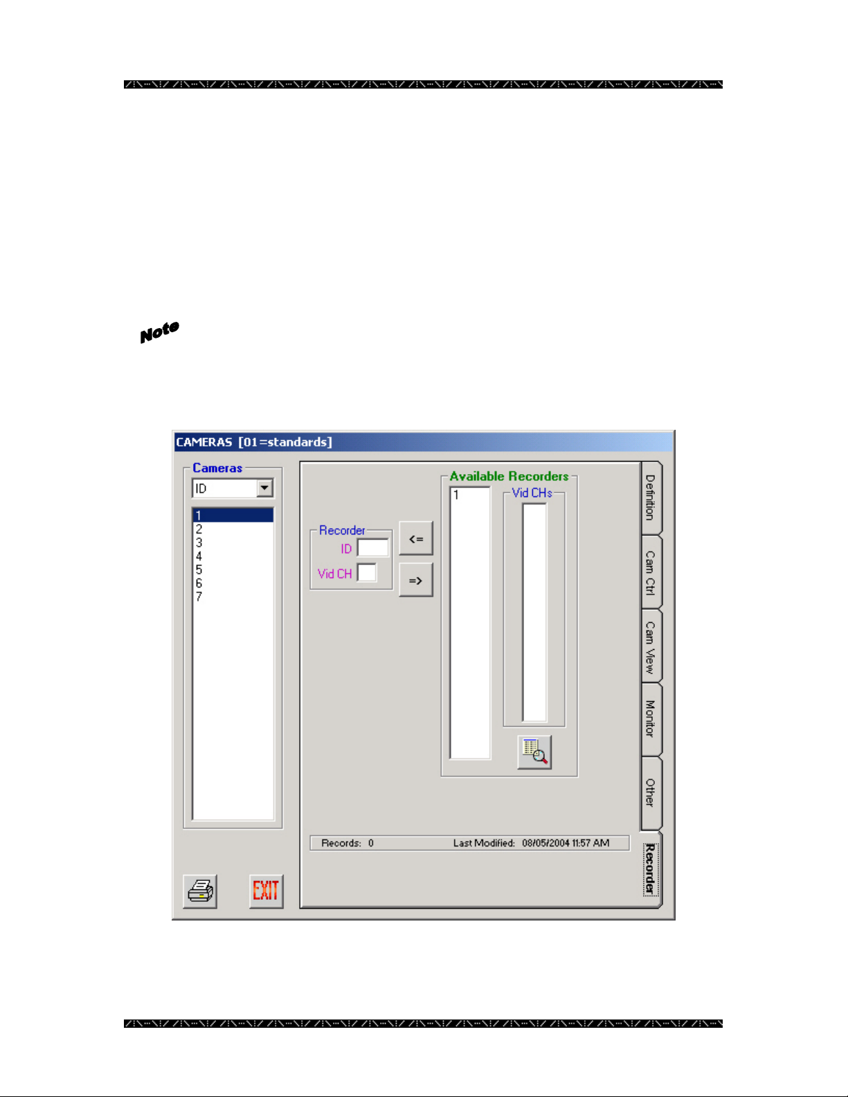
Configuration
Recorder
The Recorder tab allows the administrator to attach cameras to recorders, once a digital
recorder has been defined in Admin Console.
Click the ID number of the recorder you wish to work with from the Available
Recorders list, then select the camera ID from the Cameras list. Next, select the channel
you wish to specify from the Vid CHs (video channels) list.
Only channels that are available are listed in the Channels list.
Click the Assign Recorder button (<=) to assign the specified camera to the specified
channel, or the Remove Assign button (=>) to remove the selected camera from the
recorder ID and channel showing in the Recorder section of the screen.
72
Page 77

Configuration
System Controllers
A system controller is a device used by an operator to control specific components within
the NSS, such as: cameras, monitors, alarms, alarm outputs, etc. Controllers are
generally identified to an operator using their ID number, but can be viewed in
MPU955A Admin Console by ID, IPA, EA, or Area.
Definition
1. Select the Controllers command from the Component menu
2. Add, edit, or delete controller records as necessary using the three icons at the
bottom of this window.
73
Page 78

Configuration
SYSTEM CONTROLLERS – Definition
Field Data
Unique record ID assigned by MPU955A Admin Console as a system controller is added, in order
ID
to identify one controller to the system.
MPU955A Admin Console automatically generates this number in consecutive order. Upon adding
controllers, the system will automatically assign the next available number.
Component ID and sequence ID numbers are used primarily in the permission tabs to identify one
component or sequence from another in row and column style. Since logical and local numbers are
not necessarily unique or consecutive, and the permission grids must be displayed as consecutive,
unique numbers, MPU955A Admin Console generates these ID numbers. 1 to 128.
Unique number identifying a Monitor Surveillance Area (MSA) comprised of an array of monitors
Area
and one or more keyboard controllers. 1 to 64.
Inserting a “0” indicates area 0. This will disable the Area field in the OSD on the monitor. The
use of areas is restricted to values of 1 to 64. Only use area “0” when no areas are needed within
the entire system.
Click the Area button on the main window to view all components defined in a specific area.
Priority
Boot File
Timeout
Model
This number assigns this controller an order of precedence. Applies only when operator priorities
are the same. The controller with the lower number priority takes over the part of the system it is
addressing.
If more than one controller with the same priority is operating at the same time, access is given and
held for the latest call to a function, in other words, on a last-come first-served basis. Alarm
priorities have precedence over operator priorities. 0 to 65,534.
The name of the file used by the Ethernet keyboard’s boot process. Use the default filename unless
instructed otherwise by qualified personnel. Alphanumeric, 12 characters. The file name IS case
sensitive.
Be sure to select WV-CU850 Controller type FIRST so that the default boot name will be filled in
automatically. This is the only system controller type that will require a boot name.
If the boot name field is filled in before WV-CU850 type is selected, the default boot name will not
be inserted.
Amount of time that must elapse after the user stops entering keystrokes, before the system logs off
the operator from this controller. (hr:min:sec) 00:00:00 to 11:59:59
The controller timeout works in conjunction with the operator timeout. The system will choose the
lowest timeout value of the two.
Entering a “0” into this field will cause the timer to never expire regardless of the operator timeout
value.
Drop-down and select the correct type of system controller. This will enable or disable fields that
are specific to each particular controller. CU350 or CU360 (RS485), CU650 or CU650:64 (RS485),
CU850 (Ethernet), CU950 or CU950:64 (Ethernet), PFW100 [CU350] (RS485), PFW100 [CU850]
(Ethernet), PFW850 (Ethernet), RS232 (serial), or ActiveX.
74
Page 79

Configuration
SYSTEM CONTROLLERS – Definition
Field Data
Unique Internet Protocol Address assigned by the system administrator. Dotted decimal, 15
IPA
characters. Example: 128.010.050.125. Each of the four groups of numbers with values between 0
and 255.
Depending on the model number chosen, the following will apply:
WV-CU350: No longer supported.
WV-CU360: No longer supported.
WV-CU650, WV-CU650:64: No longer supported.
WV-CU850: A unique IPA is necessary within the scheme of the MCPU interface IPA.
WV-CU950, WV-CU950:64: A unique IPA is necessary within the scheme of the MCPU interface
IPA.
PFW100 [CU350]: Same as the WV-CU350.
PFW100 [CU850]: Same as the WV-CU850.
PFW850: Enter the IPA of the desktop computer where the PFW850 is installed, making sure it is
within the scheme of the MCPU interface IPA.
RS-232: Use the default IPA.
ActiveX: Enter the IPA of the desktop computer that ActiveX is running from, making sure it is
within the scheme of the MCPU interface IPA.
Numeric address for an Ethernet controller. This field is only required if Model WV-CU850 or
EA
WV-CU950 is chosen. Dotted hexadecimal Example: 23.56.82.13.60.82 (Also known as MAC
address.) Use all zeroes if not using DHCP.
Numeric identifier of the port used by an RS-485 controller (CU350, CU360, CU650, and
Port
PFW100A) (port 1-12) or RS232 controller (Port 1 or 2). Match the data port that this keyboard is
connected and use the proper IPA for the MCPU. Note that Port 2 is used for redundant CPU
connection, if selected by MCPU front panel switch.
This port address will be unique within the IPA specified for the MCPU.
Location
A practical name that will identify where this controller can be found. Alphanumeric, 16
characters.
A name for the controller, easy to remember, and practical. Alphanumeric, 16 characters.
Name
Manufacturer’s serial number. Alphanumeric, 16 characters.
Ser.
Permissions
Modify or copy system controller permissions in the same manner described in the
Camera Permissions section, beginning on page 67.
The Cam Ctrl permission tab allows an administrator to permit or deny a system
controller the ability to control specific cameras. The Modes section of each of the
permissions tabs is described on page 13
Copying Cam Ctrl permissions to other system controllers will also copy Cam
View permissions to the specified controller.
Allowing a system controller to control a certain camera will automatically
allow the same controller to view the specified camera.
75
Page 80

Configuration
The permission grid’s dimensions are based on the maximum capacity for the
chosen CPU size, not on physically installed components already in the
database.
The Cam View permission tab allows an administrator to permit or deny a controller to
view specific cameras.
Copying Cam View permissions to other system controllers will also copy
Cam Ctrl permissions to the specified controllers.
Denying a system controller to view a certain camera will automatically deny
the same controller to control the specified camera.
The Monitor permission tab allows an administrator to permit or deny a controller’s
ability to seize a specific monitor.
A monitor ID, if unknown, can be determined by its area and local number,
by entering each value into the appropriate boxes, and then clicking the
“Search for Monitor by Area & Local” button.
The Group Seq permission tab allows an administrator to permit or deny a controller’s
ability to control a group sequence.
If the group sequence ID is unknown, you can enter the area and local
numbers of the sequence in the appropriate boxes, and click the “Search
for Group Seq by Area & Local” button.
The Alarm permission tab allows an administrator to permit or deny a controller’s ability
to seize a specific alarm.
The Recorder permission tab allows an administrator to permit or deny a controller’s
ability to seize a specific recorder (see section on Digital Recorders)
The Alarm I/O permission tabs allows an administrator to permit or deny a controller’s
ability to seize a specific IO port.
76
Page 81

Configuration
Digital Recorders
The NSS can utilize the features of digital video recorders, once they are defined by the
Admin Console. Cameras connected to the digital recorders are configured to the video
input channel they are using.
Definition Tab
1. Select the Digital Recorders command from the Component menu
2. Add, edit, or delete recorder records as necessary using the three icons at the
bottom of the window.
Each field preceded by purple text on your computer’s display must be given
a unique number - different from other configured digital recorder records.
77
Page 82

Configuration
DIGITAL RECORDERS - Definition
Field Data
Unique record ID assigned by Admin Console as a Digital Recorder is added, in order to
ID
identify one recorder to the system. 1 to 64.
Admin Console automatically generates this number in consecutive order. Upon adding
recorders, the system will automatically assign the next available number.
Component ID and sequence ID numbers are used primarily in the permission tabs to identify
one component or sequence from another in row and column style. Since logical and local
numbers are not necessarily unique or consecutive; and the permission grids are displayed as
consecutive, unique numbers; Admin Console generates these ID numbers.
Logical
Video: - Switch
- Port
Unit Address
Digital Bitrate
Ser. (optional)
Model
Unique number assigned by an NSS administrator, usually designated by combining two
references, such as having the first 2 digits represent a logical group (such as a group of
recorders surveying a loading dock), and up to three serial digits assigned for other logical
reasons. 1 to 99,999. Examples: 8 4 001, 84002, 84003, 84004; 36 001, 36002, 36003, 36004.
An operator will select recorders to view by this logical number.
Choose the switch type to which the recorder output is connected from the drop-down list.
The video input port that is connected to the output from the recorder.
Unique Internet Protocol address assigned by the system administrator. Dotted decimal, 15
IPA
characters (including dots). Example: 128.010.050.125
Enter the recorder’s internally defined Unit Address.
Choose from the dropdown the bitrate that the recorder will support.
The serial number of the recorder.
Choose the recorder model from the dropdown. Admin Console uses this information to
determine the total number of available channels.
78
Page 83

Configuration
Channels Tab
Each digital recorder provides a number of video channels (depending on the model of
recorder). The Channels tab is used to specify which camera is connected to each of the
recorder’s channels.
1. Click in the blank LCh field and enter the Logical channel number you want to
specify for this camera
2. Click in the blank Cam field and double-click, in the panel that appears on the
right, on the camera that you wish to specify for this video channel
3. Click the green check mark to save the selection
You can only select cameras that are already configured for use by Admin
Console, and you need to know which channel they are connected to before
working on this tab. Recording is only possible from cameras that are
physically connected.
Permissions
Controller Tab
79
Page 84

Configuration
The Controller permission tab on the Digital Recorder window allows an administrator
to specify which controllers can seize the selected recorder. It shows permissions from
the recorder’s point of view. Permissions from the controller’s point of view can be found
in the Recorder Tab of the Controllers window (described in the previous section).
The last permission change made is the one that remains set. By default, all components
are allowed to access all other components. The administrator must deny permissions.
1. Click on the Controller permission tab from the Digital Recorders window
Allowing a system controller to control a certain recorder will automatically
allow the same controller to view video from the specified recorder.
Recorders are displayed in the list on the left by ID number, but can also be viewed by
logical number, IP address, or video port. The grid on the right represents the following:
First row = controller IDs 0-9, second row = controller IDs 10-19, etc.
Green blocks indicate an allowed permission, and white blocks indicate that permission is
denied.
2. Double-click on a specific controller to invert or alternate between permit or
deny
Be sure to click the save button (the picture of the floppy disk) before exiting
the Controller tab to ensure the changes will be saved correctly.
3. Highlight a row, a column, or click and hold the mouse button
to highlight a group of controllers
4. Click the Invert Grid Selection button to change the state of
the permission for the highlighted group, or
5. Click on the Permit All button to turn the entire grid green –
allowing all controllers permission to control the specified
camera, or
6. Click on the Deny All button to turn the entire grid white –
denying all controllers permission to control the specified
camera, or
7. Click on the Copy Grid button to copy the permission grid
from a specific recorder to other recorders
80
Page 85

Configuration
When copying a grid, a confirmation message will appear asking “Are you sure you want
to COPY the Controller permission for this Digital Recorder?” and explaining the
copying rules:
[1] Permissions will be copied by Digital Recorder ID.
[2] If permission already exists for a Digital Recorder that falls within the
Target range, that original permission will be overwritten.
8. Click Yes to continue or No to cancel
The copy source is the highlighted recorder ID from where the controller permissions
will be copied.
9. Enter the Target ID range of recorder ID numbers, with the beginning
number in the START box, and the ending number in the END box
Permissions existing for recorders within the specified range will be
overwritten.
81
Page 86

Viewing and Programming Modes
Clicking the View option button allows you to view permissions for the
mode chosen, and defaults to programming for the same mode. In the
case of the graphic to the left, mode 1 is set for viewing, and thereby
programming. See Scheduled Modes in the Admin Console manual.
The permissions grid reflects the contents of the mode whose view is
selected with the View option button. In the image that follows, the
permission grid is displaying the contents of mode 1.
Configuration
82
Page 87

Configuration
More than one mode can be programmed at the same time by clicking on
the Prog check boxes of the other mode numbers that you wish to
program simultaneously. This will append, or add any permissions that
are then changed on the permissions grid, but will not duplicate entire
modes or overwrite existing permissions in the other modes.
The image to the left indicates that the permissions grid would now be
displaying the contents of mode 3 (which is also by default being
programmed), and would simultaneously be programming any subsequent
changes into modes 1 and 4 as well.
It is not necessary to perform a Save for each mode viewed or programmed. Saving
permissions, when completed, automatically saves all four modes, regardless of the
current View or Prog selection.
Controllers Recorder Tab
The Recorder permission tab on the Controller window allows an administrator to specify
which recorders can be seized by the selected controller. It shows permissions from the
controller’s point of view.
By default, all components are allowed to access all other components. An administrator
must deny permissions.
1. Click on the Recorder permission tab from the Controllers window
Allowing a system controller to control a certain recorder will automatically
allow the same controller to view video from the specified recorder.
Controllers are displayed in the list on the left by ID number, but can also be viewed by
IP address (IPA), Ethernet address (EA), or area. The grid on the right represents the
following:
First row = recorder IDs 0-9, second row = recorder IDs 10-19, etc.
Green blocks indicate an allowed permission, and white blocks indicate that permission is
denied.
2. Double-click on a specific recorder to invert or alternate between permit or
deny
Be sure to click the save button (the picture of the floppy disk) before exiting
the Recorder tab to ensure the changes will be saved correctly.
83
Page 88

Configuration
3. Highlight a row, a column, or click and hold the mouse button
to highlight a group of recorders
4. Click the Invert Grid Selection button to change the state of
the permission for the highlighted group, or
5. Click on the Permit All button to turn the entire grid green –
allowing all recorders to be seized by the specified controller,
or
6. Click on the Deny All button to turn the entire grid white –
denying the selected controller access to all recorders, or
7. Click on the Copy Grid button to copy the permission grid
from a specific controller to other controllers
When copying a grid, a confirmation message will appear asking “Are you sure you want
to COPY the Recorder permission for this Controller?” and explaining the copying rules:
[1] Permissions will be copied by Controller ID.
[2] If permission already exists for a Controller that falls within the Target
range, that original permission will be overwritten.
8. Click Yes to continue or No to cancel
The copy source is the highlighted controller ID from where the recorder permissions
will be copied.
9. Enter the Target ID range of recorder ID numbers, with the beginning
number in the START box, and the ending number in the END box
Permissions existing for controllers within the specified range will be
overwritten.
84
Page 89

Configuration
10. Highlight a component within the permission grid, and click
the definition button.
A window will appear; giving a quick view of that component’s
configured definition.
For the Modes section of this tab, see on page 82.
Adding or Removing Cameras for a Defined Recorder
Once a digital recorder has been defined in Admin Console, adding or reconfiguring
cameras attached to it can be done from the Recorder tab of the Cameras screen.
1. Click the Cameras icon from the Components row of the main
menu
2. Define new cameras if necessary
3. Click the Recorder tab
4. Click the ID number of the recorder you wish to work with
5. Select the camera ID from the Cameras list
85
Page 90

Configuration
6. Select the channel you wish to specify for the camera from the
Vid CHs (video channels) list
Only channels that are available are listed in the Channels list.
7. Click the Assign Recorder ( <= ) button to assign the specified
camera to the specified channel OR the Remove Assigned
Recorder Button ( => ) to remove the selected camera from
the recorder ID and channel showing in the Recorder section
of the screen
8. Click EXIT when finished
86
Page 91

Configuration
Alarm Input/Output
Alarm input and alarm output ports are used for alarm action purposes, and although each
has a specific function, both are configured within this section. Although the system
controller operator must control the I/O ports by logical number, these ports are viewable
within MPU955A Admin Console by both ID and logical port numbers.
Although I/O Ports may be assigned individually, the assignments must conform to the
following constraints.
Each GX encoder supplies 8 ports – 4 are input ports, 4 are output ports. Because of this,
4 consecutive Ports must be configured with the same directional type - either input or
output. For example, if Port 1 is configured as an input port, then Ports 2 - 4 must be
input ports as well. Then, another group of 4 ports may be configured as output ports. In
this manner, a maximum of 1024 GX ports may be defined, unless mixed with ports from
other node types.
Similarly, SX850 ports must be configured in groups of 8 with the same directional type.
Using the same example, if Port 1 is configured as an output port, then Ports 2 – 8 must
be output ports also. A maximum of 1024 (512 for Standard CPU size) SX850 ports may
be defined, unless mixed with ports from other node types.
SX650 ports are similarly defined in groups of 256 as input ports or groups of 64 as
output ports. A maximum of 1280 SX650 ports may be defined, unless mixed with ports
from other node types.
Definition
1. Select the I/O Ports command from the Controller menu
87
Page 92

Configuration
2. Add, Edit, Delete, or Replicate alarm I/O port records as needed using the four
icons at the bottom of this window. Deleting a port will delete the entire bank that
port is part of.
88
Page 93

Configuration
A l a r m I/O PORTS – Definition
Field Data
Unique record ID assigned by MPU955A Admin Console as an I/O port is added, in order to identify the
ID
port to the system.
MPU955A Admin Console automatically generates this number in consecutive order. Upon adding I/O
ports, the system will automatically assign the next available number.
Component ID and sequence ID numbers are used primarily in the permission tabs to identify one
component or sequence from another in row and column style. Since logical and local numbers are not
necessarily unique or consecutive, and the permission grids must be displayed as consecutive, unique
numbers, MPU955A Admin Console generates these ID numbers. 1 to 1,280.
Logical
Switch Node
Dwell Time
Assigned by an NSS administrator, enabling operators to address this port. An operator will select alarm
I/O ports by logical number. 1 to 65,534.
Choose the switch type that the I/O Ports are physically connected to from the drop-down list.
Click on either Input or Output. Input Example: Fire exit door opening. Output Examples: Unlock/lock
Type
a door. Alarm to firefighters. Call for police. Call for medical rescue.
Each type must be configured in groups (banks) of 4, 8 or 256. (See below)
Choose a Bank from the drop-down list.
Bank
For each bank, 4 (for GX), 8 (for SX850) or 256 (for SX650) records are added. Although 1280 I/O
ports allowed for SX650, GX and SX850 ports are limited to 1024.
Once a record is created, only Logical number and Dwell Time can be edited.
Note that deleting a single port will delete the entire bank of which that port is member.
Input or Output port numbers are individually assigned, but automatically grouped.
I/O
Time available for a momentary output. Up to 59:59 (min:sec)
Dwell time will only be enabled for output type I/O circuits.
Permissions
Modify or copy I/O port permissions in the same manner described in the Camera
Permissions section, beginning on page 67.
The Controller permission tab allows an administrator to permit or deny a system
controller the ability to seize a specific I/O port. The Modes section of this tab is
described on page 13
The Other tab shows which Alarm ID numbers are using a particular Alarm I/O port.
The permission grid’s dimensions are based on the maximum capacity for
the chosen CPU size, not on physically installed components already in the
database.
89
Page 94

Configuration
Monitors
Monitors are generally viewed within MPU955A Admin Console by ID number, but can
be viewed by area\local number, since the user will operate the NSS by selecting a
monitor by local number within a specific area.
Area\local numbers are displayed in MPU955A Admin Console as one whole number.
The four right-most digits represent the local number and the left-most one or two digits
will represent the area. For example, 10034 represents area 1 and local number 34, or
251100 represents area 25 and local number 1100.
Definition
1. Select the Monitors command from the Components menu
90
Page 95

Configuration
2. Add, edit, delete, or replicate monitor records as needed using the four icons at
the bottom of this window.
When deleting or modifying a monitor, be sure to check the Other tab to find
references to other sections that the monitor will influence.
When changing the Monitor Surveillance Area (MSA) of a monitor, make
sure that any affected presets or alarm action target assignments are within the
same area.
Deleting a monitor will automatically delete the referenced
permissions, but will not
sequences, presets, etc.
change any other references, such as
91
Page 96

Configuration
MONITORS – Definition
Field Data
Unique record ID assigned by MPU955A Admin Console as a monitor is added, in order to identify one
ID
programmed monitor to the system.
MPU955A Admin Console automatically generates this number in consecutive order. Upon adding
monitors, the system will automatically assign the next available number.
Component ID and sequence ID numbers are used primarily in the permission tabs to identify one
component or sequence from another in row and column style. Since logical and local numbers are not
necessarily unique or consecutive, and the permission grids must be displayed as consecutive, unique
numbers, MPU955A Admin Console generates these ID numbers. 1 to 1,024.
Unique number identifying a Monitor Surveillance Area (MSA) comprised of an array of monitors and
Area
one or more keyboard controllers. 1 to 64.
Inserting a “0” indicates area 0. This will disable the Area field in the OSD on the monitor.
The use of areas is restricted to values of 1 to 64. Only use area “0” when no areas are needed within the
entire system.
Click the Area button on the main window to view all components defined in a specific area.
Unique number assigned by an NSS administrator, enabling operators to address this particular monitor
Local
within an area. 1 to 9,999.
Operators will address specific monitors by selecting the local number with an area.
Video: - Switch
- Ports
Location
Model
Choose the switch type that the monitor is physically connected to from the drop-down list.
Enter the video port number, which can be different from the ID number, if desired.
Practical name indicating where this monitor is located. Alphanumeric.
Monitor model number assigned by its manufacturer. Alphanumeric.
Monitor serial number assigned by its manufacturer. Alphanumeric.
Ser.
92
Page 97

Configuration
Replicating a Monitor Definition
1. Highlight a configured monitor and click the Replicate button
A confirmation message will appear asking “Are you sure you want to REPLICATE this
monitor within this Area?” and explaining the replication rules:
[1] Records will be generated according to ID.
[2] ID will be incremented to the next available value.
[3] Local #, Video Port will be incremented from a specified base value you assign.
[4] If a record already exists with a matching value for any of these unique fields, that
Target assignment will be skipped.
[5] All other record values will be identical to the Source record.
2. Click Yes to continue or No to cancel
Monitors can only be replicated within an area. If you wish to replicate
monitors in several areas, at least one monitor must be configured in each area.
3. Enter the number of monitors to create in the Target Size box
4. Enter the beginning base value of the local monitor number that you wish to
begin incrementing from
5. Click the green check mark to add the series of monitors, or click the red X
to cancel
After clicking the green check mark, a message will appear letting you know how many
records were actually generated, indicating if any records were skipped. See Note section
of page 66.
Monitors existing within the specified range will not be overwritten.
93
Page 98

Configuration
Permissions
Modify or Copy Monitor permissions in the same manner described in the Camera
Permissions section, beginning on page 67.
The Camera permission tab allows an administrator to permit or deny a monitor the
ability to display a specific camera.
The Controller permission tab allows an administrator to permit or deny a system
controller the ability to seize a specific monitor. The Modes section of this tab is
described on page 13
94
Page 99

Configuration
Other
The Other tab displays additional sections that a highlighted monitor will affect.
This section is informational only, and changes cannot be made to the Targets which the
specified monitor will affect. Changes must be made within the Alarm Target window.
95
Page 100

Configuration
Operators
Class Setup
An operator is one who accesses the system via a system controller, selects resources, and
controls selected system resources, such as cameras, monitors, sequences, etc.
Before an operator can be defined, an operator class needs to be created.
An operator class defines which functions an operator or groups of operators have
privileges to perform.
1. Select the Operators command from the Component menu, and then select
Class Setup
96
 Loading...