

Page 1
Central Processing Unit
Operating Instructions
Model No. WJ-MPU955
RESET
OPERATE
FAN ALARM
HDD
ACTIVE
Central Processing Unit WJ-MPU
955
Before attempting to connect or operate this product,
please read these instructions carefully and save this manual for future use.
Page 2
Caution:
Before attempting to connect or operate this product,
please read the marking on the rear panel.
CAUTION
RISK OF ELECTRIC SHOCK
DO NOT OPEN
CAUTION: TO REDUCE THE RISK OF ELECTRIC SHOCK,
DO NOT REMOVE COVER (OR BACK).
NO USER-SERVICEABLE PARTS INSIDE.
REFER SERVICING TO QUALIFIED SERVICE PERSONNEL.
The lightning flash with arrowhead symbol,
within an equilateral triangle, is intended to
alert the user to the presence of uninsulated
"dangerous voltage" within the product's
enclosure that may be of sufficient magni-
SA 1965
SA 1966
tude to constitute a risk of electric shock to
persons.
The exclamation point within an equilateral
triangle is intended to alert the user to the
presence of important operating and maintenance (servicing) instructions in the literature accompanying the appliance.
Power disconnection. Unit with or without
ON-OFF switches has power supplied to the
unit whenever the power cord is inserted
into the power source; however, the unit is
operational only when the ON-OFF switch is
in the ON position. Unplug the power cord
to disconnect the main power for all unit.
For U.S.A
NOTE: This equipment has been tested and found to comply with the limits for a Class A digital device, pursuant to
Part 15 of the FCC Rules. These limits are designed to provide reasonable protection against harmful interference
when the equipment is operated in a commercial environment. This equipment generates, uses, and can radiate
radio frequency energy and, if not installed and used in
accordance with the instruction manual, may cause harmful
interference to radio communications.
Operation of this equipment in a residential area is likely to
cause harmful interference in which case the user will be
required to correct the interference at his own expense.
FCC Caution: To assure continued compliance, (example use only shielded interface cables when connecting to computer or peripheral devices). Any changes or modifications
not expressly approved by the party responsible for compliance could void the user’s authority to operate this equipment.
The serial number of this product may be found on the bottom of the unit.
You should note the serial number of this unit in the space
provided and retain this book as a permanent record of your
purchase to aid identification in the event of theft.
Model No. WJ-MPU955
Serial No.
2
WARNING: To prevent fire or electric shock hazard, do not expose this appliance to rain or moisture. The apparatus shall not be exposed to
dripping or splashing and that no objects filled with liquids, such as vases, shall be placed on the apparatus.
Page 3

IMPORTANT SAFETY INSTRUCTIONS
1) Read these instructions.
2) Keep these instructions.
3) Heed all warnings.
4) Follow all instructions.
5) Do not use this apparatus near water.
6) Clean only with dry cloth.
7) Do not block any ventilation openings. Install in accordance with the manufacturer's instructions.
8) Do not use near any heat sources such as radiators, heat registers, stoves, or other apparatus (including amplifiers) that produce heat.
9) Do not defeat the safety purpose of the polarized or grounding-type plug. A polarized plug has two blades with
one wider than the other. A grounding-type plug has two blades and a third grounding prong. The wide blade or
the third prong are provided for your safety. If the provided plug does not fit into your outlet, consult an electrician for replacement of the obsolete outlet.
10)Protect the power cord from being walked on or pinched particularly at plugs, convenience receptacles and the
points where they exit from the apparatus.
11)Only use attachments/accessories specified by the manufacturer.
12)Use only with the cart, stand, tripod, bracket, or table specified by the manufacturer, or sold with the apparatus.
When a cart is used, use caution when moving the cart/apparatus combination to avoid injury from tip-overs.
S3125A
13)Unplug this apparatus during lightning storms or when unused for long periods of time.
14)Refer all servicing to qualified service personnel. Servicing is required when the apparatus has been damaged
in any way, such as power-supply cord or plug is damaged, liquid has been spilled or objects fallen into the
apparatus, the apparatus has been exposed to rain or moisture, does not operate normally, or has been
dropped.
3
Page 4

CONTENTS
IMPORTANT SAFETY INSTRUCTIONS ............................. 3
Introduction ....................................................................... 5
■ Overview .................................................................... 5
■ Purpose ...................................................................... 5
■ Precaution .................................................................. 5
■ Network Environment ................................................. 5
■ Limitation of Liability ................................................... 5
■ WJ-GXE900/GXD900 Version .................................... 5
■ References ................................................................. 5
■ Trademarks and Registered Trademarks .................. 5
Central Processing Unit .................................................... 6
■ Layout ........................................................................ 6
■ Panel Details .............................................................. 6
■ Mounting into the Rack .............................................. 8
■ Configuration File Modification .................................. 8
■ System Database ....................................................... 8
Connect with System Devices .......................................... 9
■ System Controllers ..................................................... 9
■ CPU Switch Unit ......................................................... 10
■ Digital Video Encoder Devices .................................. 11
■ Digital Video Decoder Devices .................................. 13
■ Setup Layer 3 Switching (L3SW) ............................... 14
■ Administration Tool .................................................... 14
■ Time Management Utility ........................................... 14
Network Security System Examples ................................. 15
■ Standard System ........................................................ 15
■ Redundant System ..................................................... 16
Main Features ................................................................... 17
■ Operator Functions .................................................... 17
■ Video Switch and Video Routing ................................ 17
■ Video Camera Function ............................................. 17
■ Tour Sequences ......................................................... 17
■ Alarm Programming and Handling ............................ 18
■ Event Operation ......................................................... 18
■ Digital Input and Output Functions ............................ 18
■ System Log ................................................................ 18
Default SYS.INI Configuration ........................................... 19
Default Database Contents .............................................. 24
OPERATING PROCEDURES (with WV-CU850) ............ 43
Log-in and Log-out ........................................................... 28
■ Log-in ......................................................................... 28
■ Log-out ....................................................................... 28
Monitor and Camera Selection ......................................... 29
■ Monitor Selection ....................................................... 29
■ Camera Selection ....................................................... 29
■ Priority Lock ............................................................... 30
Display Setting for Controller ............................................ 31
■ Adjustment of LCD Display ........................................ 31
■ Adjustment of LED Display ........................................ 31
■ IDs Display Function .................................................. 31
Controlling Camera Site Accessories ............................... 32
■ Lens Control ............................................................... 32
■ Pan/Tilt Control ........................................................... 32
■ Receiver Control ........................................................ 34
Camera Function Control .................................................. 35
■ Camera Setup ............................................................ 35
■ Changing to Black and White Pictures ...................... 35
■ Patrol Learn and Play ................................................. 36
■ Camera Panning Function ......................................... 36
Running Sequence ........................................................... 37
■ Tour Sequence ........................................................... 37
Monitor Display Control .................................................... 38
■ On-Screen Display Control ........................................ 38
Alarm Control .................................................................... 40
■ Alarm Arming Control ................................................. 40
■ To Cancel Alarms ....................................................... 40
Other Functions ................................................................ 41
■ Digital Output Function .............................................. 41
■ Area Control Function ................................................ 41
■ Joystick Calibration .................................................... 41
OPERATING PROCEDURES (with WV-CU360C) .......... 43
Log-in and Log-out ........................................................... 44
■ Log-in ......................................................................... 44
■ IDs Display Function .................................................. 45
■ Log-out ....................................................................... 45
Monitor and Camera Selection ......................................... 46
■ Monitor Selection ....................................................... 46
■ Camera Selection ....................................................... 46
■ Priority Lock ............................................................... 47
Controlling Camera Site Accessories ............................... 48
■ Lens Control ............................................................... 48
■ Pan/Tilt Control ........................................................... 48
■ Receiver Control ........................................................ 50
Camera Function Control .................................................. 51
■ Camera Setup ............................................................ 51
■ Changing to Black and White Pictures ...................... 51
■ Patrol Learn and Play ................................................. 52
■ Camera Panning Function ......................................... 52
Running Sequence ........................................................... 53
■ Tour Sequence ........................................................... 53
Monitor Display Control .................................................... 54
■ On-Screen Display Control ........................................ 54
Alarm Control .................................................................... 56
■ Alarm Arming Control ................................................. 56
■ To Cancel Alarms ....................................................... 56
TROUBLESHOOTING ..................................................... 57
Troubleshooting ................................................................ 58
Specifications .................................................................... 60
4
Page 5

Introduction
■ Overview
The WJ-MPU955 is the Central Processing Unit for the
Network Security System. The Network Security System is a
high quality video imaging system offering complete management of medium and large-scale installations. The WJMPU955 is capable of controlling up to 1,024 video inputs
and 256 video outputs with 64 system controllers. The
Network Security System is a truly network-based system,
and all the devices in the system are connected through IPbased networks.
■ Purpose
This document is to provide end users with the product
information about the WJ-MPU955 and the Network
Security System based upon it.
■ Precaution
• We recommend that you refer all tasks related to the
system installation to qualified service personnel or
system installers.
• We recommend that you make a note of all your system
settings and save them. This will help you if you are
required to change the system configuration, or if an
unexpected event or failure occurs.
• We encourage you to obtain and read all the related
documents in reference section and become familiar
with the CPU unit and other related devices and software.
• Built-in backup battery
The built-in backup battery will last approximately 3
years. The replacement cost of the built-in battery is not
covered by the warranty even if it needs to be done
within the warranty period. Consult your dealer for servicing.
• Cooling Fan
The cooling fan will operate for approximately 30 000
hours. The replacement cost of the cooling fan is not
covered by the warranty even if it needs to be done
within the warranty period. Consult your dealer for servicing.
• Hard Disk Drive
The Hard Disk Drive will operate for approximately
30 000 hours. The replacement cost of the hard disk
drive is not covered by the warranty even if it needs to
be done within the warranty period. Consult your dealer
for servicing.
■ Network Environment
The Network Security System is an IP network-based system. Creating a reliable network is the key to a successful
system. Please note that the encoder device sends a multicast stream (9.2 Mbps max. X 4 streams). Obtain confirmation from the network administrator that this bandwidth
usage will not cause a network failure.
■ Limitation of Liability
In no event shall Matsushita Electric Industrial Co., Ltd. be
liable to any party or any person, except for replacement or
reasonable maintenance of the product, for the cases
including, but not limited to below:
• Any damage and/or loss, including without limitation,
direct or indirect, special, consequential or exemplary,
arising out of, or relating to, the product;
• Personal injury and/or any damage caused by inappropriate use or negligent operation by the user;
• Unauthorized disassembly, repair, or modification of
the product by the user;
• Any problem, consequential inconvenience, or loss or
damage, arising out of the system being combined with
devices from a third party
■ WJ-GXE900/GXD900 Version
• To use WJ-GXE900 and WJ-GXD900 devices with WJMPU955, the devices' firmware must be version 2.00 or
later.
• The version is displayed on the home page of either
device when accessed via a web browser.
• If the version is earlier than 2.00, contact your sales
representative.
■ References
[1] Admin Console User's Guide
[2] MPEG2 Encoder and MPEG2 Decoder Operating
Instructions
[3] WJ-MPS850 Instructions
[4] Time Management Utility User's Guide
■ Trademarks and Registered Trademarks
• Intel and Pantium are trademarks of Intel Corporation.
• Other names of companies and products contained in
this operating instructions may be trademarks or registered trademarks of their respective owners.
5
Page 6
PARALLEL
REDUNDANT
CPU
SATELLITE
MODE
10BASE-T / 100BASE-TX
3
OTHER
ENCODER
DECODER
SYSTEM
CONTROLLER
DATA 12 DATA 11 DATA 10 DATA 9 DATA 8 DATA 7 DATA 6 DATA 5 DATA 4 DATA 3 DATA 2 DATA 1
PERIPHERAL INTERFACE (RS-232C
)
(
RS-485
)
SYSTEM
CONTROLLER
21
SATELLITE
STANDALONE
YESNO
AC IN125V 6.3A
SIGNAL
GND
y u !2
i
o
!0 !1 !3 !4
Central Processing Unit
OPERATE
RESET
FAN ALARM
Central Processing Unit WJ-MPU
HDD
ACTIVE
tr
qw!5 !5e
The WJ-MPU955 is a main component of the Network Security System. It uses an Intel®X86 processor based computer running in the multiple tasks operating environment. The system also supports two WJ-MPU955 working together to form a redundant system.
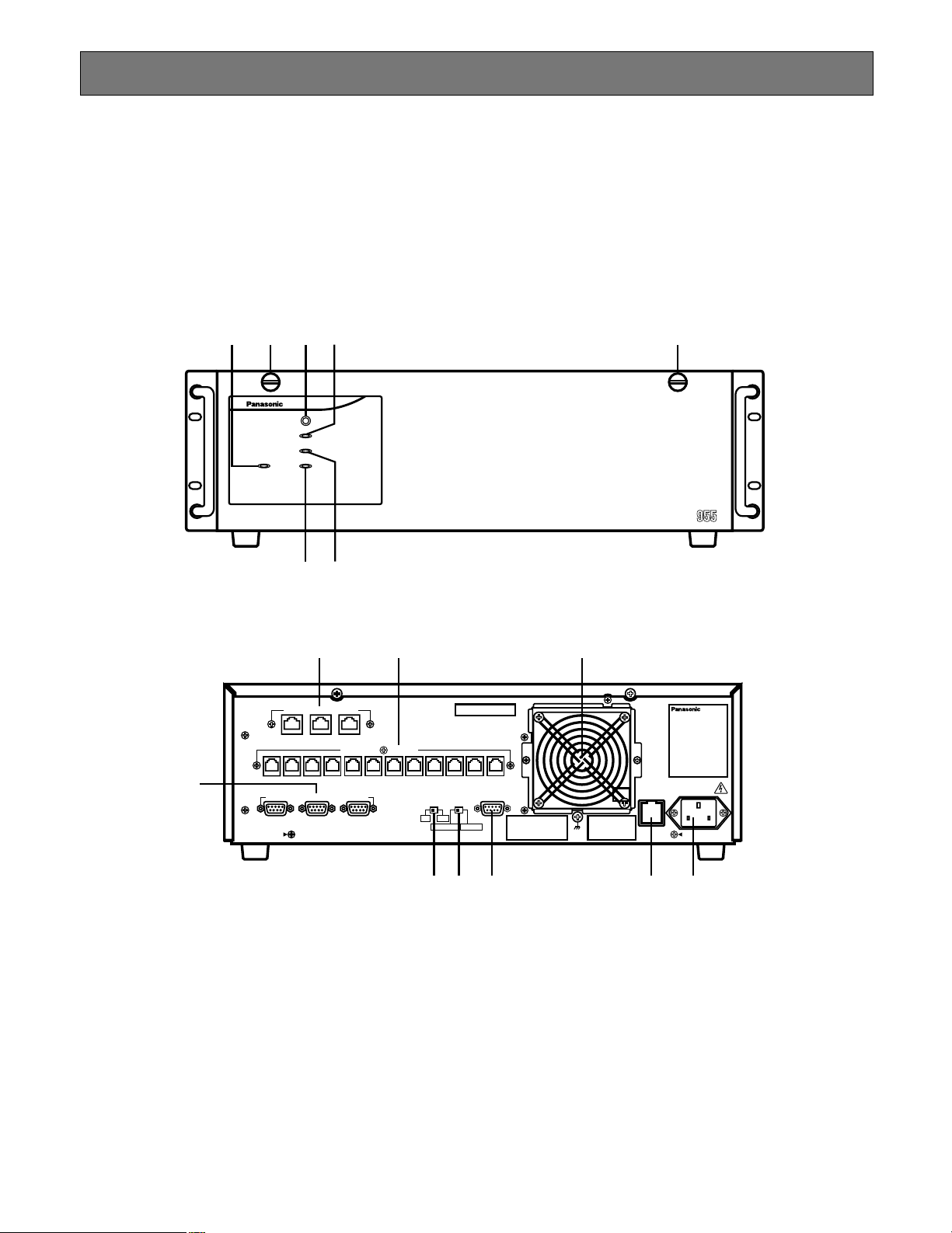
■ Layout
The following diagrams are the front panel and the rear panel of the WJ-MPU955.
● Front Panel
● Rear Panel
■ Panel Details
q Operation Indicator (OPERATE)
Operation indicator q is on when the power of the WJMPU955 is turned on. The power switch of the CPU is
located underneath the front panel. Remove the front
panel by removing the two screws on the panel.
w Reset Button (RESET)
The RESET button w is recessed inside the front panel
hole to the right on the OPERATE indicator. Press this
button when the CPU rejects control from outboard
equipment.
Since the reset button is located 2/3 of an inch behind
the front panel, you will need to use a small screwdriver
or other tool that is less than 1/6 of an inch in diameter,
and more than 1 inch long. If you are unable to access
the reset button using this method, remove the front
panel and press the button.
e Fan Alarm Indicator (FAN ALARM)
The FAN ALARM indicator e indicates the cooling fan
status. This LED lights when a temperature rise in the
CPU is detected. Turn the power off and refer servicing
to qualified service personnel.
6
Page 7

r Hard Disk Drive Indicator (HDD)
The HDD indicator r indicates the hard disk drive status.
t Active Indicator (ACTIVE)
The ACTIVE indicator t indicates the system status of
the WJ-MPU955.
y Ethernet Ports (10BASE-T/100BASE-TX)
The Ethernet Ports y exchange control data via
Ethernet. The CPU can contain up to three Ethernet
ports. In a standard setup, we suggest you use the first
Ethernet port [SYSTEM CONTROLLER] for system controllers while the second port [ENCODER/DECODER]
for video encoders and decoders. The third port
[OTHER] is reserved for future use.
u Controller Ports [SYSTEM CONTROLLERS (RS-485)]
The controller ports u are provided for controlling the
system with WV-CU360C system controllers. Up to 12
controllers can be connected.
i Peripheral Interface Ports [PERIPHERAL INTER-
FACE (RS-232C)]
These ports i are reserved for future use or factory
tests.
o Redundant CPU Selector (REDUNDANT CPU)
The selector o can be set to either a redundant system
or a standalone system. The factory default setting is
NO, for standalone.
!0 Mode Selector (SATELLITE MODE)
The mode selector !0 is always kept in STANDALONE
position.
!1 Parallel Port (PARALLEL)
The parallel port !1 is used to connect to the WJMPS855 CPU Switch Unit for a redundant system.
!2 Cooling Fan Unit
The cooling fan unit !2 prevents the temperature of the
CPU from rising. Do not block the ventilation opening
on the cover.
!3 Fuse Holder
The fuse holder !3 is shown in rear view diagram.
!4 AC Inlet Socket (AC IN)
Plug the power cord (supplied as a standard accessory) into this socket !4 and connect it to an AC outlet.
!5 Screws to access the power switch.
7
Page 8
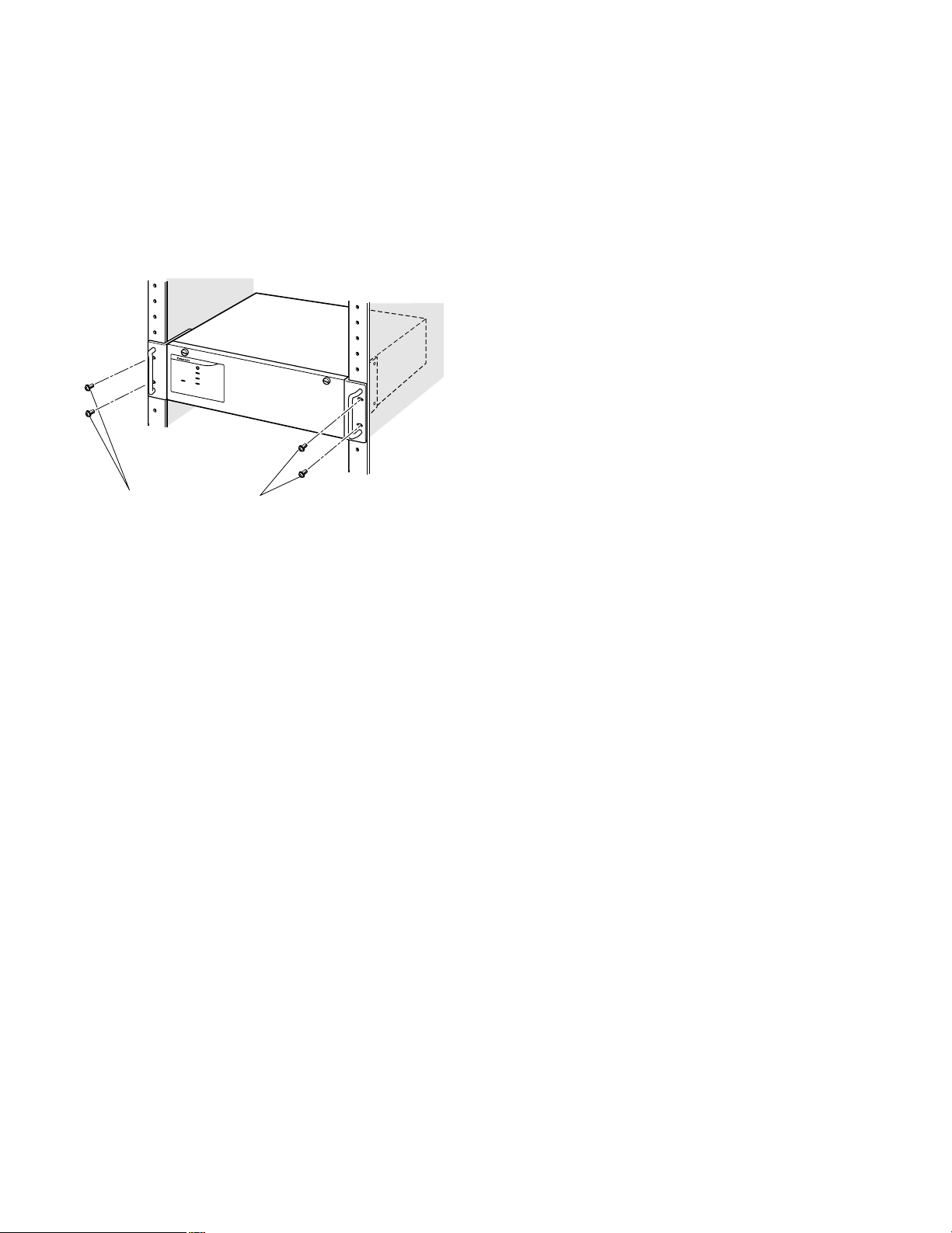
■ Mounting into the Rack
The CPU unit (WJ-MPU955) should be mounted into the
rack as shown in the following diagram. Here are the steps:
1. Remove the four rubber feet by removing four screws
from the bottom of the CPU unit
2. Install the CPU unit in the rack, securing it with the four
screws
3. Secure the rear of the appliance to the rack by using
the additional mounting brackets procured locally if the
rack is subject to vibration
RESET
FAN ALARM
OPERATE
HDD
ACTIVE
Rack mounting screws
(Local content)
■ System Database
The system database contains system devices, system
resources, and system programmable events and automation information. The system administrator can configure the
system database using the administration tool. The CPU
unit contains a default database when it arrives from the
factory.
A default database file is also provided on the CD-ROM.
The contents of the default database file – 01= sample.adm
– appear in the Default Database Contents section. (Refer
to p.24)
The cooling fans inside the CPU unit keep the CPU unit
working properly. They are subject to wear and need to be
replaced periodically. Do not block the ventilation slots on
the cover to prevent the appliance from overheating.
Always keep the temperature in the rack below 45 °C
(113 °F).
■ Configuration File Modification
The system configuration file is referred to as the SYS.INI
file. It contains system-wide configuration information, and
can be modified by the operators through an administration
tool. See reference [1].
The CPU unit contains default SYS.INI file. (Refer to p.19)
The CPU unit should work with the default system configuration file set by the factory at the time of shipping. To modify the default configuration file, you can use the administration tool (Admin Console). From the Admin Console main
menu:
• Select CPU Units from the main bar’s Domain;
• Select Sys tab from the CPU System Configuration
screen;
• Upload the SYS.INI file from the CPU unit using the ‘Get
from CPU’ button in the SYS Transfer section;
• Modify the system configuration file that appears in the
document area of the window;
• Save the system configuration file using the ‘Save’ button in the SYS Archive section;
• Download the configuration file using the ‘Put to CPU’
button in the SYS Transfer section;
• Reboot the CPU unit
8
Page 9
Connect with System Devices
In addition to the WJ-MPU955, users require other system
devices in order to form the Network Security System.
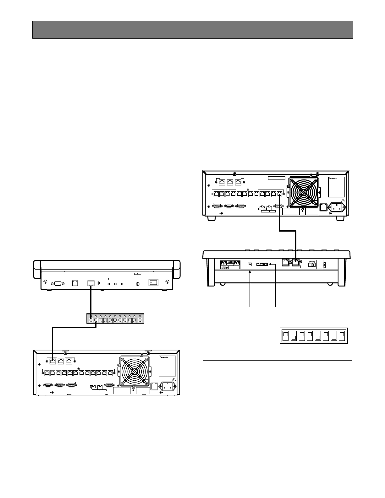
■ System Controllers
A system controller is an operator console, and it provides
a user interface for operators to interact with the Network
Security System. The system can support up to 64 system
controllers.
● Ethernet-Based Controllers
The Ethernet-based controller is called a CU850 controller
(WV-CU850). It connects to the CPU unit’s Ethernet port
(see Panel Details y) through an Ethernet hub in an IPbased local area network.
● Ethernet-Based Controller Setup
To add CU850 controllers to the system, use the administration tool (Admin Console) and add an entry to the system
controller database. You need to assign a controller ID for
each controller, and enter the Ethernet address from the
bottom of the each controller. See reference [1] for more
information.
● RS485-Based Controllers
There is an RS485-based controller - the CU360C (WVCU360C). The controller connect to the CPU unit through its
RS485 controller port (see Panel Details u). The system
can support up to twelve RS485 based controllers.
● RS485-Based Controller Setup
To add a CU360C controller to the system, use the administration tool (Admin Console) and add an entry to the system
controller database. You need to assign a controller ID for
each controller, and enter the RS485 port number where
the controller is going to connect to. See reference [1] for
more information.
10BASE-T / 100BASE-TX
ENCODER
SYSTEM
OTHER
DECODER
CONTROLLER
DATA 12 DATA 11 DATA 10 DATA 9 DATA 8 DATA 7 DATA 6 DATA 5 DATA 4 DATA 3 DATA 2 DATA 1
PERIPHERAL INTERFACE (RS-232C
SYSTEM
(
)
RS-485
CONTROLLER
)
3
21
REDUNDANT
CPU
STANDALONE
PARALLEL
SATELLITE
MODE
YESNO
SATELLITE
SIGNAL
GND
AC IN125V 6.3A
WV-CU360C
RS-232C DATA
ETHERNET
CONTRAST BRIGHT BRIGHT
172.18.0.1
ETHERNET
GYGTEM
CAMERA
OTHER
CONTROLLER
CROSS POINT
OSD
SYSYTEM
(
)
RS–485
CONTROLLER
DATA 12 DATA 11 DATA 10 DATA 9 DATA 8 DATA 7 DATA 6 DATA 5 DATA 4 DATA 3 DATA 2 DATA 1
PERIFERAL INTERFACE (RS–232C
)
1
23
REDUNDANT
CPU
STANDALONE
YESNO
RSATELLITE
MODE
PARALLEL
SATELLITE
LEDLCD
DC12V IN
Switching HUB
SIGNAL
GND
WV-CU850
POWER
ON OFF
125V 3.0A
Central Processing Unit
AC IN
0
1
9
RISK OF ELECTRIC
SHOCK. DO NOT OPEN
RISQUE DE CHOCK ELECTRODES
NE PAS OUVRIR
2
8
3
7
4
6
5
CONTROLLER No.
DATAMODE
CONTROLLER No. MODE
Set this switch always
Set as shown in below
to 1
OFF
ON
12345678
DC 9V IN
MODE
9
Page 10
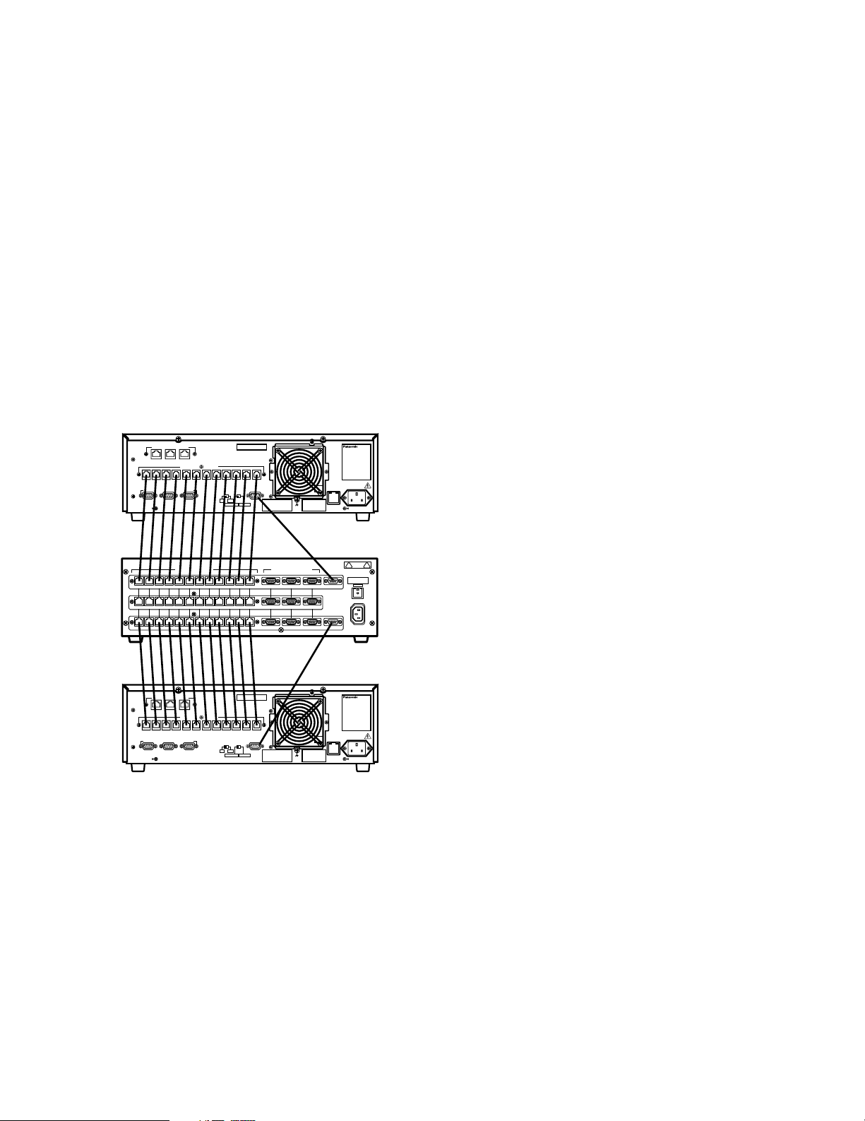
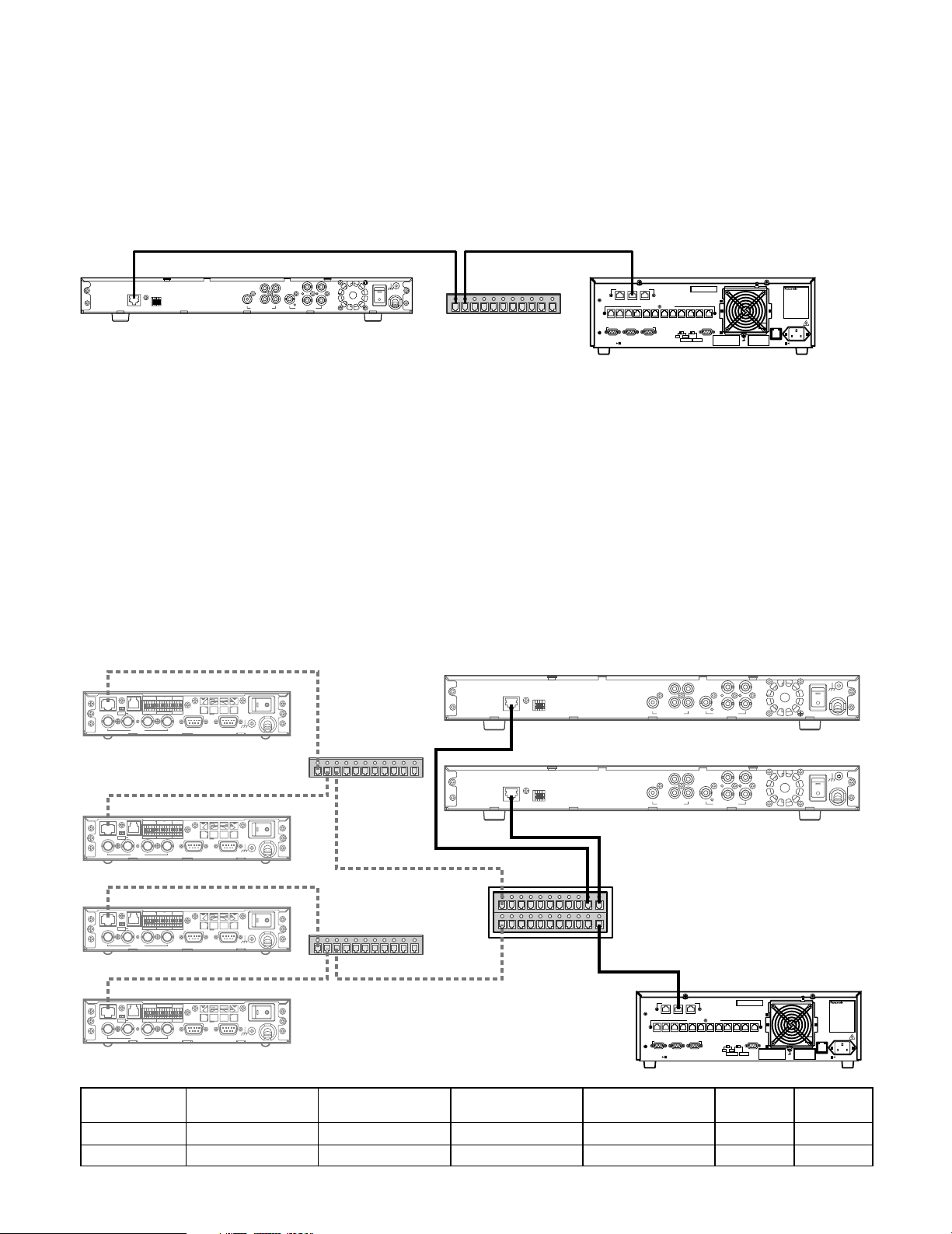
■ CPU Switch Unit
The standard system consists of one CPU unit. In order to
create a redundant Network Security System, customers
would need to purchase two CPU units (or one additional
CPU unit if the system is already in place) plus a CPU
Switch Unit, WJ-MPS850. The CPU Switch Unit is a computer that monitors and manages both CPU units.
● Operation
At any given time that the system is running, one of the
CPU units is in an Active state and the other is in a Standby
state. If the Active CPU fails, the CPU Switch Unit will automatically switch the Standby unit to an Active state.
● Connect with CPU Units
The CPU Switch Unit connects to the CPU units through its
parallel port (see section !1).
A CPU
10BASE-T / 100BASE-TX
ENCODER
SYSTEM
OTHER
DECODER
CONTROLLER
SYSTEM
(
)
RS-485
CONTROLLER
DATA 12 DATA 11 DATA 10 DATA 9 DATA 8 DATA 7 DATA 6 DATA 5 DATA 4 DATA 3 DATA 2 DATA 1
PERIPHERAL INTERFACE (RS-232C
)
3
21
REDUNDANT
CPU
STANDALONE
PARALLEL
SATELLITE
MODE
YESNO
SATELLITE
SIGNAL
GND
AC IN125V 6.3A
SYSTEM CONTROLLER (RS-485)
DATA 3
DATA 4
DATA 5
DATA 6
DATA 7
DATA 8
DATA 9
DATA 10
DATA 11
DATA 12
DATA 3
DATA 4
DATA 5
DATA 6
DATA 7
DATA 8
DATA 9
DATA 10
DATA 11
DATA 12
DATA 1
DATA 2
DATA 1
DATA 2
DATA 1DATA 2DATA 3DATA 4DATA 5DATA 6DATA 7DATA 8DATA 9DATA 10DATA 11DATA 1 2
PERIPHERAL INTERFACE (RS-232C)
3 2 1
321
321
DIAGNOSTIC
INPUT
MAIN CPU-ACT
TARGET
MAIN CPU-STANDBY
CAITION
PUSH
FUSE
AC IN
B CPU
10BASE-T / 100BASE-TX
OTHER
ENCODER
SYSTEM
DECODER
CONTROLLER
SYSTEM
(
)
RS-485
CONTROLLER
DATA 12 DATA 11 DATA 10 DATA 9 DATA 8 DATA 7 DATA 6 DATA 5 DATA 4 DATA 3 DATA 2 DATA 1
PERIPHERAL INTERFACE (RS-232C
)
3
21
REDUNDANT
CPU
STANDALONE
PARALLEL
SATELLITE
MODE
YESNO
SATELLITE
SIGNAL
GND
AC IN125V 6.3A
• Connect the RS485 modular cables between the controller ports (RS-485) of the CPU units and the controller ports (RS-485) of the CPU Switch Unit.
• Connect the diagnostic cables between parallel ports
of the CPU units and the diagnostic input ports of CPU
Switch Unit.
• Set the redundant CPU selector to YES on the rear of
the A and B CPU units.
10
Page 11
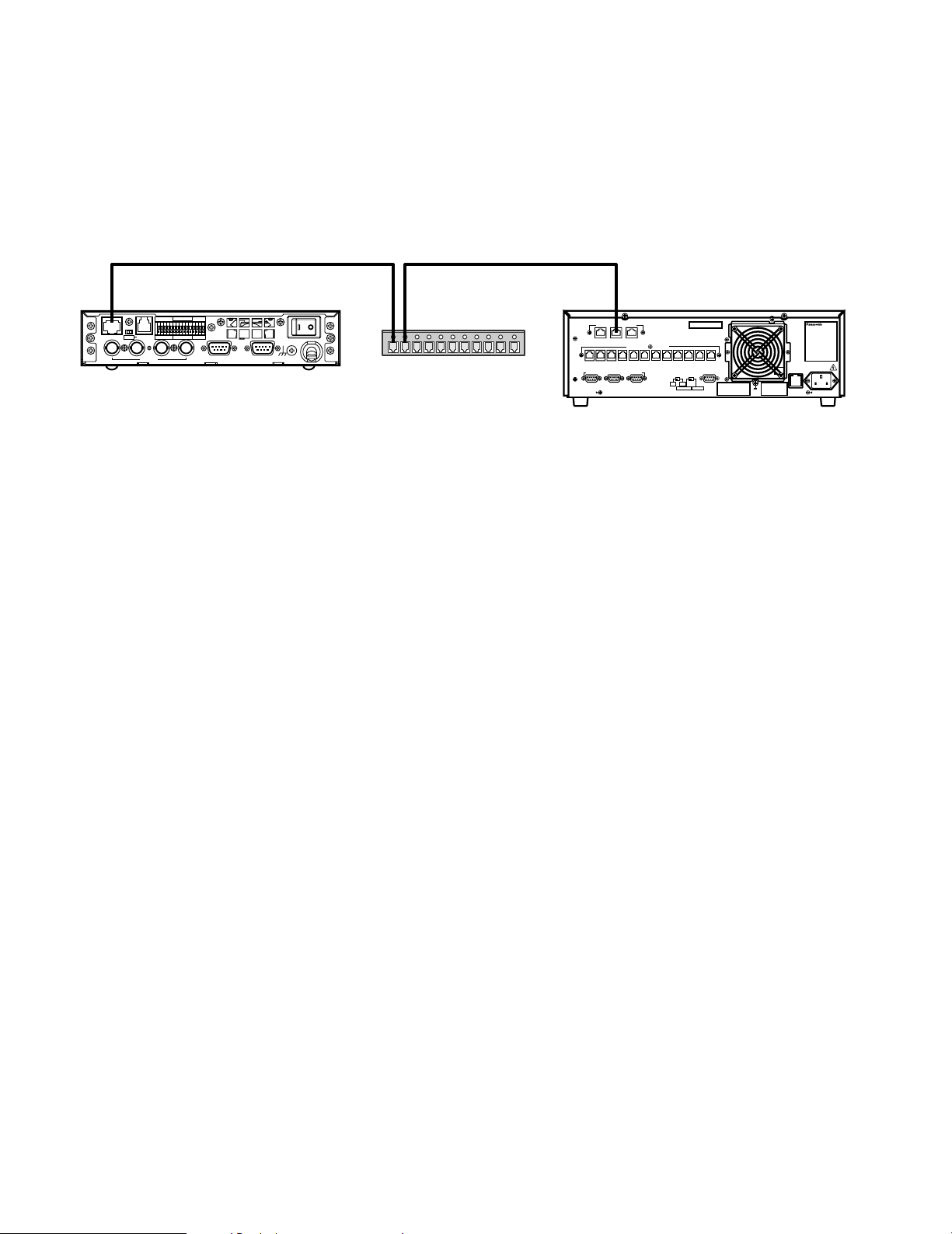
■ Digital Video Encoder Devices
Digital video encoder devices refer to MPEG2 video encoder devices (WJ-GXD900). They connect to the CPU unit through an
Ethernet switching hub in an IP based network. See reference [2].
● Connect with CPU unit
The video encoders connect with the CPU unit through its Ethernet port (see Panel Details y) and one or more switching hub
units. The system can support up to 256 video encoder devices.
ON OFF
TERM
100BASE-TX RS-485
4
432 1G4321GGV
23
RESET
+
–
G
1
POWER
ON OFF
AUDIO INVIDEO OUTVIDEO IN
GND
SIGNAL
Switching HUB
10BASE-T / 100BASE-TX
ENCODER
SYSTEM
OTHER
DECODER
CONTROLLER
SYSTEM
(
)
RS-485
CONTROLLER
DATA 12 DATA 11 DATA 10 DATA 9 DATA 8 DATA 7 DATA 6 DATA 5 DATA 4 DATA 3 DATA 2 DATA 1
PERIPHERAL INTERFACE (RS-232C
)
3
21
REDUNDANT
CPU
STANDALONE
PARALLEL
SATELLITE
MODE
YESNO
SATELLITE
AC IN125V 6.3A
SIGNAL
GND
ALARM IN
TRIGGER OUT
● Setup from Administration Tool
In order to be added to the Network Security System, an encoder device must be entered into the digital device database. In
Admin Console, select Switch Nodes from the Domain menu, select Digital (GX) from the sub-menu that appears, and then
enter the information for the encoder device. Please note, you need to know the Rotary Switch (SW1 A, B, C) readings from the
encoder device. Rotary Switch settings must be unique for all the encoder and decoder devices. See reference [1].
192.168.200.200
11
Page 12
● Setup Encoder Itself
In order to communicate with the CPU unit, the encoder device must also be configured. You can access the encoder device
through its Web interface using Microsoft
be filled into the table.
192.168.1.10
POWER
AUDIO INVIDEO OUTVIDEO IN
SIGNAL
ON OFF
GND
ON OFF
100BASE-TX RS-485
TERM
4
WJ-GXE900
TRIGGER OUT
4321G4321GGV
23
ALARM IN
1
RESET
+
–
G
®
Internet Explorer. Following is an example of the system layout and information to
WJ-GXD900
1000BASE-T
100BASE-TX
2
RESET
V+–G
MIX
QUAD
3
4
3
4
VIDEO OUTAUDIO OUT
ON
SIGNAL GND
OFF
POWER
1
2
1
192.168.3.11
WJ-GXD900
1000BASE-T
100BASE-TX
2
RESET
V+–G
MIX
QUAD
3
4
4
3
VIDEO OUTAUDIO OUT
ON
SIGNAL GND
OFF
POWER
1
2
1
192.168.4.11
Switching HUB
ON OFF
100BASE-TX RS-485
TERM
4
WJ-GXE900
ON OFF
100BASE-TX RS-485
TERM
4
WJ-GXE900
ON OFF
100BASE-TX RS-485
TERM
4
WJ-GXE900
Encoder #
1
2
3
4
TRIGGER OUT
4321G4321GGV
23
TRIGGER OUT
4321G4321GGV
23
TRIGGER OUT
4321G4321GGV
23
ALARM IN
RESET
+
–
G
1
ALARM IN
RESET
+
–
G
1
ALARM IN
RESET
+
–
G
1
Operation Mode
Main CPU mode
Main CPU mode
Main CPU mode
Main CPU mode
192.168.1.11
POWER
SIGNAL
AUDIO INVIDEO OUTVIDEO IN
192.168.2.10
POWER
SIGNAL
AUDIO INVIDEO OUTVIDEO IN
192.168.2.11
POWER
SIGNAL
AUDIO INVIDEO OUTVIDEO IN
ON OFF
GND
ON OFF
GND
ON OFF
GND
Switching HUB
IP Address
192.168.1.10
192.168.1.11
192.168.2.10
192.168.2.11
192.168.4.1192.168.3.1192.168.1.1
L3SW
192.168.2.1 192.168.200.1
Subnet Mask
255.255.255.0
255.255.255.0
255.255.255.0
255.255.255.0
Default Gateway
192.168.1.1
192.168.1.1
192.168.2.1
192.168.2.1
192.168.200.200
10BASE-T / 100BASE-TX
OTHER
ENCODER
SYSTEM
DECODER
CONTROLLER
SYSTEM
(
)
RS-485
CONTROLLER
DATA 12 DATA 11 DATA 10 DATA 9 DATA 8 DATA 7 DATA 6 DATA 5 DATA 4 DATA 3 DATA 2 DATA 1
)
PERIPHERAL INTERFACE (RS-232C
REDUNDANT
SATELLITE
CPU
MODE
YESNO
3
21
SATELLITE
STANDALONE
DNS
0.0.0.0
0.0.0.0
0.0.0.0
0.0.0.0
PARALLEL
WJ-MPU955
SIGNAL
GND
Rotary
Switch
0-0-1
0-0-2
0-0-3
0-0-4
AC IN125V 6.3A
12
Page 13
■ Digital Video Decoder Devices
Decoder devices refer to MPEG2 video decoder devices (WJ-GXD900). They connect with the CPU unit through an Ethernet
switching hub in an IP based network. See reference [2].
● Connect with CPU unit
The video decoders connect with CPU unit through its Ethernet port (see Panel Details y) and one or more switching hub
units. The system can support up to 64 video decoder devices.
1000BASE-T
100BASE-TX
WJ-GXD900
2
RESET
V+–G
MIX
142
QUAD
314
VIDEO OUTAUDIO OUT
ON
3
SIGNAL GND
OFF
POWER
Switching HUB
10BASE-T / 100BASE-TX
OTHER
ENCODER
SYSTEM
DECODER
CONTROLLER
SYSTEM
(
)
RS-485
CONTROLLER
DATA 12 DATA 11 DATA 10 DATA 9 DATA 8 DATA 7 DATA 6 DATA 5 DATA 4 DATA 3 DATA 2 DATA 1
)
PERIPHERAL INTERFACE (RS-232C
REDUNDANT
SATELLITE
CPU
MODE
YESNO
3
21
SATELLITE
STANDALONE
PARALLEL
AC IN125V 6.3A
SIGNAL
GND
● Setup from Administration Tool
In order to be added to the Network Security System, a decoder device must be entered into the digital device database. In
Admin Console, select Switch Nodes from the Domain menu, select Digital (GX) from the sub-menu that appears, and then
enter the information for the decoder device. Please note, you need to know the Rotary Switch (SW1 A, B, C) readings from the
decoder device. Rotary Switch settings must be unique for all the encoder and decoder devices. See reference [2].
● Setup Decoder Itself
In order to communicate with the CPU unit, the decoder device must also be configured. You can access the decoder device
through its Web interface using Microsoft
be filled into the table.
192.168.1.10
POWER
SIGNAL
AUDIO INVIDEO OUTVIDEO IN
192.168.1.11
POWER
SIGNAL
AUDIO INVIDEO OUTVIDEO IN
192.168.2.10
POWER
SIGNAL
AUDIO INVIDEO OUTVIDEO IN
192.168.2.11
POWER
SIGNAL
AUDIO INVIDEO OUTVIDEO IN
ON OFF
GND
ON OFF
GND
ON OFF
GND
ON OFF
GND
ON OFF
TERM
100BASE-TX RS-485
4
WJ-GXE900
ON OFF
100BASE-TX RS-485
TERM
4
WJ-GXE900
ON OFF
TERM
100BASE-TX RS-485
4
WJ-GXE900
ON OFF
TERM
100BASE-TX RS-485
4
WJ-GXE900
TRIGGER OUT
4321G4321GGV
23
TRIGGER OUT
4321G4321GGV
23
TRIGGER OUT
4321G4321GGV
23
TRIGGER OUT
4321G4321GGV
23
ALARM IN
1
ALARM IN
1
ALARM IN
1
ALARM IN
1
RESET
+
–
G
RESET
+
–
G
RESET
+
–
G
RESET
+
–
G
®
Internet Explorer. Following is an example of the system layout and information to
WJ-GXD900
1000BASE-T
100BASE-TX
2
RESET
V+– G
MIX
QUAD
3
4
3
4
VIDEO OUTAUDIO OUT
ON
SIGNAL GND
OFF
POWER
1
2
1
192.168.3.11
Switching HUB
1000BASE-T
100BASE-TX
2
1
2
RESET
V+– G
MIX
QUAD
3
4
4
VIDEO OUTAUDIO OUT
1
3
WJ-GXD900
ON
SIGNAL GND
OFF
POWER
192.168.4.11
192.168.4.1192.168.3.1192.168.1.1
L3SW
Switching HUB
192.168.2.1 192.168.200.1
192.168.200.200
10BASE-T / 100BASE-TX
OTHER
ENCODER
SYSTEM
DECODER
CONTROLLER
SYSTEM
(
)
RS-485
CONTROLLER
DATA 12 DATA 11 DATA 10 DATA 9 DATA 8 DATA 7 DATA 6 DATA 5 DATA 4 DATA 3 DATA 2 DATA 1
)
PERIPHERAL INTERFACE (RS-232C
21
REDUNDANT
SATELLITE
CPU
MODE
YESNO
3
SATELLITE
STANDALONE
PARALLEL
WJ-MPU955
SIGNAL
GND
AC IN125V 6.3A
Decoder #
1
2
Operation Mode
Main CPU mode
Main CPU mode
IP Address
192.168.3.11
192.168.4.11
Subnet Mask
255.255.255.0
255.255.255.0
Default Gateway
192.168.3.1
192.168.4.1
DNS
0.0.0.0
0.0.0.0
Rotary
Switch
1-0-0
1-0-1
13
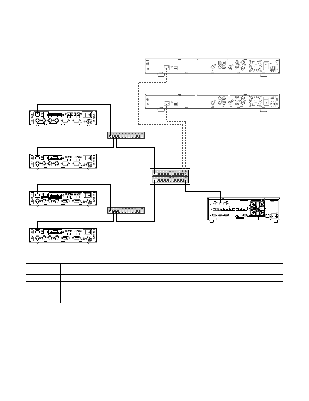
Page 14
■ Setup Layer 3 Switching (L3SW)
Layer 3 Switching refers to a class of high-performance routers optimized for wire speed Ethernet routing and switching services. It is required to support Internet Group Management Protocol (IGMPv2).
Based on the sample described in "Digital Video Encoder Devices" and "Digital Video Decoder Devices", the following table
contains Ethernet ports information for the L3SW.
Port #
1
2
3
4
5
IP Address Connection
192.168.1.1
192.168.2.1
192.168.3.1
192.168.4.1
192.168.200.1
Encoder #1,2
Encoder #3,4
Decoder #1
Decoder #2
WJ-MPU955
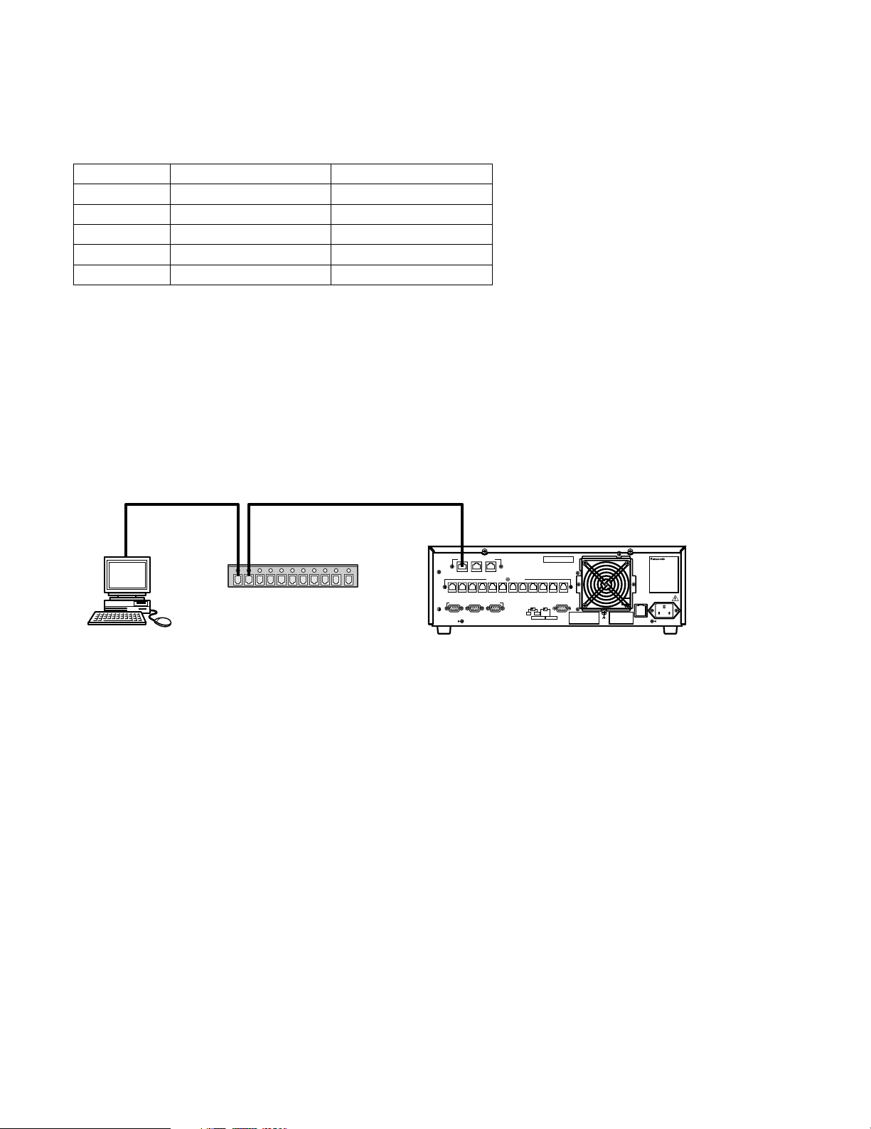
■ Administration Tool
The administration tool (Admin Console) is a system database management software. The software operates in the Microsoft
Windows®environment. See reference [1] for details.
To connect an administration station with the CPU unit, first install the Admin Console software to a Microsoft
based personal computer, and then enter the CPU unit IP address in the tool’s CPU screen which appears when the tool is ran
the first time. The tool communicates with the CPU using the IP/FTP protocol.
Switching HUB
PC
with Admin Console
10BASE-T / 100BASE-TX
ENCODER
SYSTEM
OTHER
DECODER
CONTROLLER
SYSTEM
(
)
RS-485
CONTROLLER
DATA 12 DATA 11 DATA 10 DATA 9 DATA 8 DATA 7 DATA 6 DATA 5 DATA 4 DATA 3 DATA 2 DATA 1
PERIPHERAL INTERFACE (RS-232C
)
3
21
REDUNDANT
CPU
STANDALONE
PARALLEL
SATELLITE
MODE
YESNO
SATELLITE
AC IN125V 6.3A
SIGNAL
GND
®
Windows®-
®
■ Time Management Utility
The Time Management Utility (TMU) is software used for time configuration. The software operates in the Microsoft®Windows
environment. We recommend that the Time Management Utility be installed on the same computer that runs the administration
tool.
To connect the TMU to the CPU unit, operators should select IPA setup from the TMU main menu, and enter the IP address of
the CPU unit. See the Time Management Utility Installation and configuration manual for more details See reference [4].
14
®
Page 15
Network Security System Examples
850
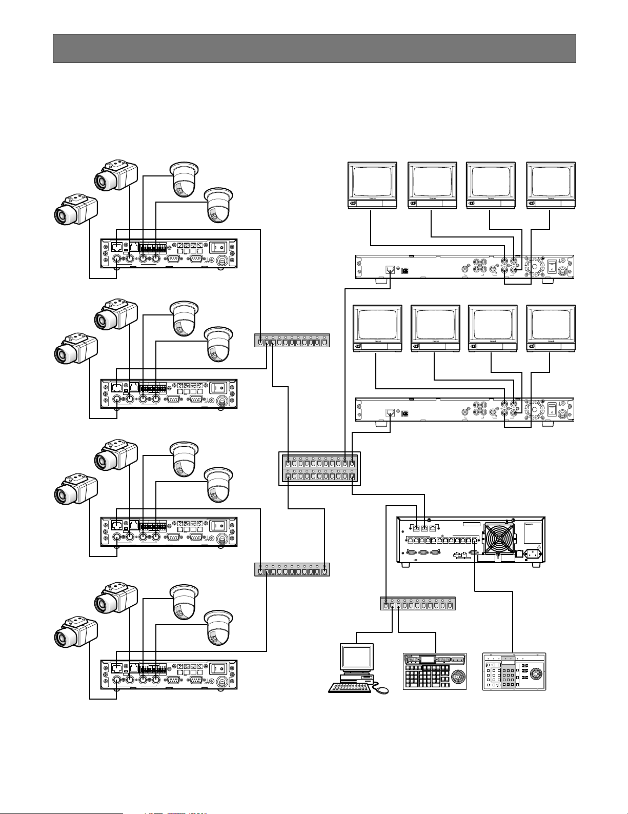
■ Standard System
The standard system contains one CPU unit. It can handle up to 256 encoder devices, up to 64 decoder devices, one administration station, and up to 64 system controllers. The IP addresses in the following diagram are the default addresses of the
CPU network ports.
ON OFF
100BASE-TX RS-485
TERM
4
ON OFF
100BASE-TX RS-485
TERM
4
ON OFF
TERM
100BASE-TX RS-485
4
TRIGGER OUT
4321G4321GGV
23
TRIGGER OUT
4321G4321GGV
23
TRIGGER OUT
4321G4321GGV
23
ALARM IN
1
ALARM IN
1
ALARM IN
1
RESET
+
–
G
192.168.1.10
POWER
ON OFF
SIGNAL
AUDIO INVIDEO OUTVIDEO IN
GND
WJ-GXE900
1000BASE-T
100BASE-TX
192.168.3.11
2
RESET
V+–G
MIX
314
142
QUAD
VIDEO OUTAUDIO OUT
ON
3
SIGNAL GND
OFF
POWER
WJ-GXD900
Switching HUB
RESET
+
–
G
192.168.1.11
POWER
ON OFF
AUDIO INVIDEO OUTVIDEO IN
GND
SIGNAL
WJ-GXE900
192.168.1.1 192.168.3.1 192.168.4.1
1000BASE-T
100BASE-TX
192.168.4.11
2
RESET
V+–G
MIX
314
142
QUAD
VIDEO OUTAUDIO OUT
ON
3
SIGNAL GND
OFF
POWER
WJ-GXD900
L3SW
192.168.2.1 192.168.200.1
192.168.200.200172.18.0.1
10BASE-T / 100BASE-TX
OTHER
ENCODER
SYSTEM
DECODER
CONTROLLER
SYSTEM
(
)
RS-485
CONTROLLER
DATA 12 DATA 11 DATA 10 DATA 9 DATA 8 DATA 7 DATA 6 DATA 5 DATA 4 DATA 3 DATA 2 DATA 1
)
PERIPHERAL INTERFACE (RS-232C
21
REDUNDANT
SATELLITE
CPU
MODE
YESNO
3
SATELLITE
STANDALONE
PARALLEL
SIGNAL
GND
WJ-MPU955
AC IN125V 6.3A
AUDIO INVIDEO OUTVIDEO IN
192.168.2.10
POWER
ON OFF
SIGNAL
GND
RESET
+
–
G
WJ-GXE900
Switching HUB
ON OFF
TERM
100BASE-TX RS-485
4
TRIGGER OUT
4321G4321GGV
23
ALARM IN
1
Switching HUB
INFORMATION
RESET
+
–
G
192.168.2.11
POWER
ON OFF
SIGNAL
AUDIO INVIDEO OUTVIDEO IN
GND
WJ-GXE900
PC
MONITOR
ACK
BUSY
ALARM
ACK
PREV
GROUP
PRESET
S-CTL IDOPE ID
GROUP
PAUSE STOP
SEQ
TOUR
REV
SEQ
RUN
OSD
OSD SERVICE
CAMERA
ALARM LINK OPERATE
BUSY
LOCK
F.1 F.2 F.3
F.4
F.5 F.6
RESET
ARM
CMENU
CMENU
ALL
RESET
NEXT
VER
FWD
RUN
MONITOR
LOCK
CAM
OFF
ON
FUNC
IRIS
CLOSE
OPEN
LOGOUT
AREA
231
CAM ID
T&D
GEN
AUX1 OFF AUX1 ON
WIPER
VLD S
ALM S
SYS S
DEFAULT
CALL
PGM
(
)
ALARM
5964
PRESET
PRESET
FOCUS
L
ALL
MSTATUS
AUX2 OFF AUX2 ON
VLD H
ALM H
NEAR FAR
DIGITAL
CAM
87
OUT
POSI
DEF OFF
DEF ON
AUTO FOCUS
ZOOM
CAMERA
CLEAR
0
(ENTER)
WIDE TELE
(
)
ESC
AUTO PAN
EXIT
BLK
System Controller WU–CU
DOWN
UP
850
R
OPERATE LINK ALARM MONITOR CAMERA BUSY PROHIBITED
ALARM
RESETACK
ALL RESET
DISARM
PROGRAM
GROUP
PRESET
PRESET
CAM ID
GEN
NEXTPREV
AUX1 OFF
AUX1 ON
WIPER
S-CTL ID
OPE ID
LOG OUT
MON STATUS
ALL
STOPPAUSE
CALL
PRESET
CAM MENU ONCAM MENU OFF
AUX2 OFF
AUX2 ON
GROUP
TOUR
F1
SEQ
SEQ
DEF OFF DEF ON
CLEAR
CAMERA
(
)
(
ESC
F2
SHIFT
ENTER
MONITOR
OSD
AUTO
LOCK
PAN
)
WV-CU850 WV-CU360C
AUTO FOCUS
IRIS
AUTO IRIS
FOCUS
ZOOM
System ControllerWV-CU
For Matrix Switcher (System 850
OPENCLOSE
FARNEAR
TELEWIDE
DOWN
350
)
UP
RL
with Admin Console
15
Page 16
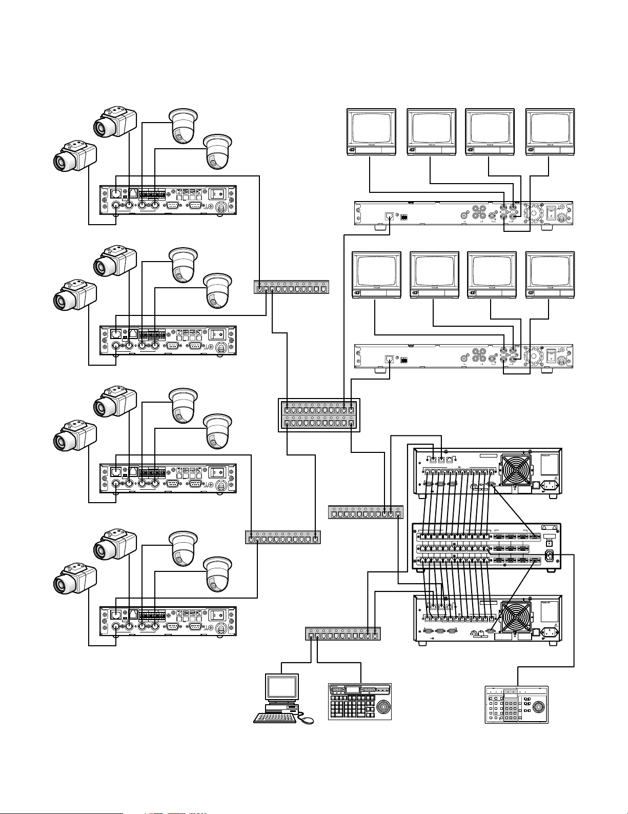
■ Redundant System
850
The redundant system requires two CPU units and a CPU Switch Unit. It can also handle up to 256 encoder devices, up to 64
decoder devices, one administration station, and up to 64 system controllers.
ON OFF
TERM
100BASE-TX RS-485
4
ON OFF
TERM
100BASE-TX RS-485
4
ON OFF
TERM
100BASE-TX RS-485
4
TRIGGER OUT
4321G4321GGV
23
TRIGGER OUT
4321G4321GGV
23
TRIGGER OUT
4321G4321GGV
23
ALARM IN
1
ALARM IN
1
ALARM IN
1
RESET
+
–
G
192.168.1.10
POWER
ON OFF
AUDIO INVIDEO OUTVIDEO IN
GND
SIGNAL
WJ-GXE900
1000BASE-T
100BASE-TX
192.168.3.11
2
RESET
V+–G
MIX
142
QUAD
314
VIDEO OUTAUDIO OUT
ON
3
SIGNAL GND
OFF
POWER
WJ-GXD900
Switching HUB
RESET
+
–
G
192.168.1.11
POWER
ON OFF
AUDIO INVIDEO OUTVIDEO IN
GND
SIGNAL
WJ-GXE900
192.168.1.1 192.168.3.1 192.168.4.1
1000BASE-T
100BASE-TX
192.168.4.11
2
RESET
V+–G
MIX
142
QUAD
314
VIDEO OUTAUDIO OUT
ON
3
SIGNAL GND
OFF
POWER
WJ-GXD900
L3SW
192.168.2.1 192.168.200.1
AUDIO INVIDEO OUTVIDEO IN
192.168.2.10
POWER
ON OFF
GND
SIGNAL
RESET
+
–
G
WJ-GXE900
172.18.0.1
192.168.200.200
10BASE-T / 100BASE-TX
OTHER
ENCODER
SYSTEM
DECODER
CONTROLLER
CONTROLLER
DATA 12 DATA 11 DATA 10 DATA 9 DATA 8 DATA 7 DATA 6 DATA 5 DATA 4 DATA 3 DATA 2 DATA 1
PERIPHERAL INTERFACE (RS-232C
21
SYSTEM
(
)
RS-485
)
3
REDUNDANT
PARALLEL
SATELLITE
CPU
MODE
YESNO
SATELLITE
STANDALONE
SIGNAL
GND
AC IN125V 6.3A
WJ-MPU955
16
ON OFF
TERM
100BASE-TX RS-485
4
TRIGGER OUT
4321G4321GGV
23
ALARM IN
1
Switching HUB
Switching HUB
192.168.200.201
SYSTEM CONTROLLER (RS-485)
DATA 4
DATA 5
DATA 6
DATA 7
DATA 8
DATA 9
DATA 10
DATA 11
DATA 12
DATA 4
DATA 5
DATA 6
DATA 7
DATA 8
DATA 9
DATA 10
DATA 11
DATA 12
DATA 3
DATA 3
DATA 1
DATA 2
DATA 1
DATA 2
DATA 1DATA 2DATA 3DATA 4DATA 5DATA 6DATA 7DATA 8D ATA 9DATA 10DATA 1 1DATA 12
PERIPHERAL INTERFACE (RS-232C)
3 2 1
321
321
DIAGNOSTIC
MAIN CPU-ACT
TARGET
MAIN CPU-STANDBY
INPUT
CAITION
PUSH
FUSE
AC IN
WJ-MPS850
INFORMATION
F.1 F.2 F.3
231
CAM ID
VLD S
5964
MSTATUS
VLD H
87
0
BLK
172.18.0.2
CAMERA
ALARM LINK OPERATE
BUSY
F.4
F.5 F.6
CAM
CMENU
CMENU
FUNC
OFF
ON
UP
IRIS
CLOSE
OPEN
LOGOUT
AREA
GEN
AUX1 OFF AUX1 ON
WIPER
SYS S
DEFAULT
CALL
PGM
PRESET
PRESET
FOCUS
R
L
ALL
AUX2 OFF AUX2 ON
NEAR FAR
DIGITAL
CAM
OUT
POSI
DEF OFF
DEF ON
AUTO FOCUS
ZOOM
CAMERA
CLEAR
DOWN
(ENTER)
WIDE TELE
(
)
ESC
AUTO PAN
EXIT
System Controller WU–CU
850
RESET
+
–
G
192.168.2.11
POWER
ON OFF
AUDIO INVIDEO OUTVIDEO IN
GND
SIGNAL
WJ-GXE900
PC
Switching HUB
MONITOR
ACK
LOCK
BUSY
ALARM
ACK
RESET
ARM
ALL
RESET
PREV
NEXT
GROUP
PRESET
T&D
S-CTL IDOPE ID
VER
ALM S
GROUP
PAUSE STOP
(
)
ALARM
SEQ
ALM H
TOUR
REV
FWD
SEQ
RUN
RUN
MONITOR
OSD
LOCK
OSD SERVICE
WV-CU850
with Admin Console
10BASE-T / 100BASE-TX
OTHER
ENCODER
SYSTEM
DECODER
CONTROLLER
SYSTEM
(
)
RS-485
CONTROLLER
DATA 12 DATA 11 DATA 10 DATA 9 DATA 8 DATA 7 DATA 6 DATA 5 DATA 4 DATA 3 DATA 2 DATA 1
PERIPHERAL INTERFACE (RS-232C
21
)
3
REDUNDANT
PARALLEL
SATELLITE
CPU
MODE
YESNO
SATELLITE
STANDALONE
SIGNAL
GND
WJ-MPU955
OPERATE LINK ALARM MONITOR CAMERA BUSY PROHIBITED
ALARM
RESETACK
ALL RESET
DISARM
PROGRAM
GROUP
PRESET
PRESET
CAM ID
GEN
NEXTPREV
AUX1 OFF
AUX1 ON
WIPER
OPE ID
S-CTL ID
LOG OUT
MON STATUS
ALL
STOPPAUSE
CALL
PRESET
CAM MENU ONCAM MENU OFF
AUX2 OFF
AUX2 ON
GROUP
TOUR
F1
SEQ
SEQ
DEF OFF DEF ON
CLEAR
CAMERA
(
)
(
ESC
F2
SHIFT
ENTER
MONITOR
OSD
AUTO
LOCK
PAN
WV-CU360C
AC IN125V 6.3A
System ControllerWV-CU
350
)
For Matrix Switcher (System 850
IRIS
OPENCLOSE
UP
AUTO IRIS
FOCUS
FARNEAR
AUTO FOCUS
RL
ZOOM
TELEWIDE
DOWN
)
Page 17

Main Features
■ Operator Functions
● Operator Area Changes
The system can be divided into multiple areas (up to 64),
and an operator can change from one area to another if
they have the necessary permission.
● Operator Log On and Off
Operators are assigned a user ID and password by a system administrator. A user ID and password are required for
any operator to log on to the system. System administrators
can specify to automatically log operators off if there is no
activity for a pre-defined time period.
● Operator Class
The system allows administrators to define operator classes
with up to 29 different privileges, and then assign each
operator to one of the defined classes. The privileges are:
permission override, area change, alarm select, all alarm
reset, alarm acknowledge and reset, all alarm arm and disarm, alarm arm and disarm, alarm status (not currently supported), alarm history (not currently supported), digital output port control, camera select, camera position, camera
preset programming, camera menu on and off, camera
function enable, camera receiver, camera setup data, camera lock, camera lock override, tour sequence, group
sequence (not currently supported), group preset (not currently supported), all sequence stop (not currently supported), sequence controller programming, video loss, monitor
select, monitor lock, on screen display on and off, time and
date on and off.
● Operator Priority
The system administrator can assign a priority to each
operator. When two operators compete for system
resources, only the operator with the higher priority gets the
resources.
■ Video Camera Function
● Camera Control
The system provides operators with the camera control
functions. The supported functions are: pan, tilt, zoom,
focus, and iris.
● Camera Operation
The system provides operators with the following camera
operation functions:
• Camera menu control
• Camera preset call and programming
• Camera receiver control
■ Tour Sequences
● Program the Tour Sequences
This function allows administrators to program tour
sequences, and store them in the system database.
The WJ-MPU955 can execute 20 tour sequence steps per
second. If the WJ-MPU955 is asked to perform more than
20 steps in a single second, it will automatically form 20step groups, and alternate their execution over a period of
two or more seconds.
● Tour Sequence Operation
The tour sequence operation includes start, stop, pause,
run, next step, and previous step.
■ Video Switch and Video Routing
This function allows operators to switch video from one
video source to another, if the permission is granted. For
multiple operators competing for the same resource, it only
allows the highest priority operator to perform this function.
The next highest priority operator gains control when the
highest priority operator releases the resource.
17
Page 18

■ Alarm Programming and Handling
● Program the Alarm
This function allows administrators to program alarms,
assign alarm display targets, and define alarm actions.
● Control Alarm
Alarm controls are operator functions. These functions allow
the highest priority operator to seize the alarm and control
it. These functions also allow the next highest priority operator to gain control after the highest priority operator releases the alarm.
The alarm controls include:
• Arm and disarm alarms
• Acknowledge active alarms
• Reset acknowledged or active alarms
The system also supports automatically resetting and
acknowledging alarms through configuration by the administration tool (Admin Console).
■ System Log
The system supports following system logs:
• Operator log
• Alarm log
• Video loss log
● Control Alarm Action
The system supports the following alarm actions:
• Camera spots
• Tour sequences
• Text display
The system supports up to 10 alarm actions, and allows
operators to control acknowledged alarm actions.
■ Event Operation
The function allows administrators to program system
events. The event function currently supports following
operations:
• Camera spot
• Tour sequence
• Arm and disarm alarm
• Up to 4 system modes
■ Digital Input and Output Functions
This function allows operators to select and set digital output ports. The system alarm function can program the digital output ports as part of the alarm state change indication.
The system alarm function can also program the digital
input ports as alarm trigger sources.
18
Page 19

Default SYS.INI Configuration
In most cases, you will not need to change the settings in the sys.ini file. However, if changes are necessary, the MPU955 CPU
must be rebooted.
Text appearing in blue is explanatory, and not part of the sys.ini file.
Interface section
The CPU can incorporate up to three Ethernet network interface cards.
[INTERFACES]
***{ Number of interfaces in the system}
Numinterfaces=3
The number used here is the number of the Ethernet ports on MPU955 CPU.
***{ Interface Definitions }
***{ Interface<Number>=<IPA>,<SUBNET MASK>,<BOOT SERVER IPA> }
***{ !! Note: The InterfaceX IPAs must match the MainX CPU }
***{ hardware settings in order for the System to }
***{ operate correctly!!
***{ MainA CPU }
In a standalone system, the MPU955 CPU should use the IP addresses that follow. In this case, the {MainB
CPU}’s interface numbers should be commented with asterisks.
Interface0=192.168.200.200,255.255.255.0,192.168.200.200
Interface0 is an interface for GX devices.
Interface1=172.18.0.1,255.255.0.0,172.18.0.1
Interface1 is an interface for system controller.
Interface2=172.16.192.1,255.255.0.0,172.16.192.1
Interface2 is used for SNMP, SNTP feature. (Not currently supported)
***{ MainB CPU }
In a redundant system, the second MPU955 CPU should use following IP addresses (remove the asterisks
below). In this case, {MainA CPU}’s interface numbers should be commented with asterisks.
*Interface0=192.168.200.201,255,255,255,0,192.168.200.201
*Interface1=172.18.0.2,255.255.0.0,172.18.0.2
*Interface2=172.16.192.2,255.255.0.0,172.16.192.2
Frames section
[CAUTION] This section does not apply to the MPU955 system, and should not be changed.
[FRAMES]
***{ MX Frame definition from Admin file }
***{ MXSW has format <num_rows>,<num_cols>,<interface_num> }
***{ All others use <num_functions>,<interface_num> }
***{ All 0's used for digital-only systems. }
MXSWFunction=0,0,0
MXCONTFunction=0,0
MXOSDFunction=0,0
MXDIOFunction=0,0
MXRMSFunction=0,0
19
Page 20

Procs section
This section tells the system which interface is to be used by certain process files.
[PROCS]
***{ Process Interface Assignments }
***{ Format: <Process Name>=<interface_num> }
***{ Set these three to the interface_num of the Ethernet keyboards: }
Keybp=1
Mxconts=1
Mxpfw=1
“1” means interface1 in [INTERFACES] section. MPU955 CPU has 3 software processes (listed above) to communicate to a CU850. All processes should use same interface number. Factory default setup is interface “1”.
***{ Set Swcpu to the same interface_num for all unit CPUs: }
Swcpu=1
“1” measn interface1 in [INTERFACES] section. In case of redundant system, Both CPUA and CPUB must be
assigned the same interface_num. Factory default setup is interface “1”.
***{ Set UnitManager to the same interface_num for all system CPUs: }
UnitManager=2
Not currently supported
***{ Set CSntp to the interface_num for EXTERNAL SNTP operation: }
CSntp=2
Not currently supported
***{ Set SSntp to the same interface_num for all system CPUs: }
SSntp=2
Not currently supported
***{ Set SNMPAgent to the same interface_num for all system CPUs: }
SNMPAgent=2
“1” means interface1 in [INTERFACES] section. Factory default setup is interface “2”.
OSD section
All settings in this section are set to factory default, which provide the best monitor layout.
[OSD]
***{ Initial OSD display position }
***{ Alarm text is placed on the General Status line. }
***{ Format: <DisplayItemPosition>=<x-position>,<y-position> }
TimeDatePosition=1,1
CamTitlePosition=1,16
MonStatusPosition=1,15
GenStatusPosition=1,14
***{ Time-Date, Camera Title and Camera ID Controls }
***{ Code 2 takes effect only if source is MXOSD }
***{ Format: <Control Name>=<control code> }
***{ control code 0 - OFF }
***{ control code 1 - ON }
***{ control code 2 - By Operator }
TimeDateControl=2
CamTitleControl=2
CamIDControl=2
***{ Time and Date display format }
***{ Format: TimeDateFormat=<format> }
***{ format 0 - DD/MM/YYYY }
***{ format 1 - MM/DD/YYYY }
***{ format 2 - DD/Mmm/YYYY }
***{ format 3 - YYYY/MM/DD }
***{ format 4 - Mmm/DD/YYYY }
***{ format 5 - DD/MM/'YY }
***{ format 6 - MM/DD/'YY }
***{ format 7 - DD/Mmm/'YY }
***{ format 8 - 'YY/MM/DD }
***{ format 9 - Mmm/DD/'YY }
20
Page 21

TimeDateFormat=1
***{ Time-Hour Display format }
***{ Format: TimeHourFormat=<format> }
***{ format 0 - 12 Hour }
***{ format 1 - 24 Hour }
TimeHourFormat=0
UNIT section
[CAUTION] This section should not be changed.
[UNIT]
***{ The unit ID should be the same as the one defined in }
***{ the Global Admin database for this unit. }
***{ For single-unit systems, use ID=1. (ID=0 is invalid) }
ID=1
RMS section
[CAUTION] This section does not apply to the MPU955 system, and should not be changed.
[RMS]
***{ This section is optional. It is not required unless }
***{ System defaults are not acceptable. Delete the }
***{ single asterisks below to make this section active. }
***{ Required only for PSDIC RMS
*NumDedicatedRecorders=0
*NumBackupRecorders=0
*Review=0,0,0
*Backup=0,0,0
*IdleSource=0
*Links=0,0
LOG section
This section sets the frequency with which log files are saved to hard disk. The defaults below have the logs being
copied every 10 minutes and stored for 7 days.
[LOG]
***{ This section is optional. It is not required unless }
***{ System defaults are not acceptable. Delete the }
***{ single asterisks below to make this section active. }
***{ Log generation/save characteristics }
***{ Format: <LogFileName>=<Minutes>,<Days> }
***{ Minutes = Frequency to copy to HD (1 - 30 min) }
***{ Note: Values outside this range = 1 min. }
***{ Days = days to save on HD (5 - 30) }
UserLog=10,7
SwLog=10,7
(SwLog is not currently supported)
AlarmLog=10,7
VideoLossLog=10,7
21
Page 22

RS232ALARM section
[CAUTION] This section should not be changed.
All RS232C ports can be set in Admin Console for the alarm interface. This section describes the characteristics
for the external alarm port only. Other use of the port, such as for an external controller, must be configured using
Admin Console.
[RS232ALARM]
***{ This section is optional. It is not required unless }
***{ System defaults are not acceptable. Delete the }
***{ single asterisks below to make this section active. }
***{ Enable/Disable Serial Alarms by port }
***{ Format: AlarmPort=<port 1>,<port 2>,<port 3> }
***{ port # = use "1" to indicate desired port (only one) }
***{ port # = use "0" to indicate ports not desired }
*AlarmPort=1,0,0
ALARMTEXTDISPLAY section
This section sets up the characteristics of the alarm text - whether alarm text only or alarm and action text.
There is a 40 character maximum for alarm text.
[ALARMTEXTDISPLAY]
***{ This section is optional. It is not required unless }
***{ System defaults are not acceptable. Delete the }
***{ single asterisks below to make this section active. }
***{ Alarm Text Display format }
***{ Format: AlarmTextDisplay=<option> }
***{ option 0 - Display Alarm Text only }
***{ option 1 - Display both Alarm Text (20 chars) }
***{ and Action Text (20 chars) }
*AlarmTextDisplay=0
SYSTEM section
[CAUTION] This section should not be changed.
Use Admin Console to select the correct CPU size.
[SYSTEM]
***{ This section is optional. It is not required unless }
***{ System defaults are not acceptable. Delete the }
***{ single asterisks below to make this section active. }
***{ Format: Keyboards=<num of controllers on this unit> }
***{ Cameras=<num of cameras on this unit> }
***{ Monitors=<num of monitors on this unit> }
*Keyboards=64
*Cameras=1024
*Monitors=256
ROUTING section
[CAUTION] This section should not be changed.
This section allows the setting of certain network parameters. If you believe changes are necessary, consult your
network administrator.
***{ This section is optional to the system. It is only required for external gateway. }
***{ Only one default gateway entry is allowed! }
***{ Format: default=<gateway IPA> }
22
Page 23

The factory default settings below are up is commented out by “*”.
default=192.168.200.1
***{ Network entries must be grouped together although any number of entries is allowed. }
***{ Format: network=<destination>,<gateway>,<netmask> }
*network=64.0.0.0,192.168.200.44,255,0,0,0
*network=88.0.0.0,192.168.200.88,255,0,0,0
*network=33.5.0.0,192.168.200.66,255,0,0,0
*network=64.0.0.0,192.168.200.55,255,0,0,0
***{ Host entries must be grouped together although any number of entries is allowed. }
***{ Format: host=<destination>,<gateway> }
*host=33.44.55.66,192.168.200.66
*host=11.22.33.44,192.168.200.44
SNTP section
[CAUTION] This section should not be changed.
This section allows changes to Simple Network Time Protocol parameters, if SNTP is implemented.
***{ This section is optional. It is not required unless }
***{ System defaults are not acceptable. Delete the }
***{ single asterisks below to make this section active. }
***{ This section lists user-defined client SNTP values, }
***{ sync rates and an external server address. }
***{ }
***{ Format: (VALUES INTERNAL TO THIS UNIT) }
***{ ClientMode=<mode> (act as an SNTP client) }
***{ modes: 0 - Internal (default) }
***{ 1 - Unicast }
***{ 2 - Anycast }
***{ 3 - Broadcast }
***{ ServerMode=<mode> (to expose its timestamp to }
***{ other units) }
***{ modes: 0 - Off }
***{ 1 - On (default) }
***{ InternalFrequency=<time frequency of sync (secs)> }
***{ -default is 600 sec (10 min) }
***{ }
***{ (VALUES FOR EXTERNAL CONNECTION) }
***{ NTPServerIPA=<IPA> of SNTP server }
***{ -for Unicast mode only; optional for }
***{ modes 0,2,3. }
***{ ExternalFrequency=<time frequency of sync (secs)> }
***{ -default is 18000 sec (5 hrs) }
***{ TZOffset=<hour> time zone offset from GMT }
***{ (+,-12 in integer values) }
***{ DaylightSaving=<on/off> (applies for the local }
***{ time zone) }
***{ on/off: 0 - off }
***{ 1 - on }
*ClientMode=1
*ServerMode=1
*InternalFrequency=600
*NTPServerIPA=192.168.200.XXX
*ExternalFrequency=18000
*TZOffset=5
*DaylightSaving=1
23
Page 24

Default Database Contents
This section indicates the contents of the default database - sample.adm - that is included on the CD-ROM.
GX DEVICES
ID
I/F
IPA
EA
ENC
Input port
DEC
Output port
GXDIN
Input port
Address
1
2
3
4
5
6
CAMERAS
ID
1
2
3
4
5
6
7
8
9
10
11
12
13
14
15
16
0
192.168.1.1
0
192.168.1.2
0
192.168.2.1
0
192.168.2.2
0
192.168.3.1
0
192.168.4.1
Logical #
1
2
3
4
5
6
7
8
9
10
11
12
13
14
15
16
00:00:00:00:00:00
00:00:00:00:00:00
00:00:00:00:00:00
00:00:00:00:00:00
00:00:00:00:00:00
00:00:00:00:00:00
Switch
Digital
Digital
Digital
Digital
Digital
Digital
Digital
Digital
Digital
Digital
Digital
Digital
Digital
Digital
Digital
Digital
Ports
1
2
3
4
5
6
7
8
9
10
11
12
13
14
15
16
1 - 4
5 - 8
9 - 12
13 - 16
–
–
Compensation
Short
Short
Short
Short
Short
Short
Short
Short
Short
Short
Short
Short
Short
Short
Short
Short
Bitrate
6.144
6.144
6.144
6.144
6.144
6.144
6.144
6.144
6.144
6.144
6.144
6.144
6.144
6.144
6.144
6.144
–
–
–
–
1 - 4
5 - 8
Model
WV-CS854A
WV-CS854A
WV-CS854A
WV-CS854A
WV-CS854A
WV-CS854A
WV-CS854A
WV-CS854A
WV-CS854A
WV-CS854A
WV-CS854A
WV-CS854A
WV-CS854A
WV-CS854A
WV-CS854A
WV-CS854A
–
–
–
–
–
–
CAMERA1
CAMERA2
CAMERA3
CAMERA4
CAMERA5
CAMERA6
CAMERA7
CAMERA8
CAMERA9
CAMERA10
CAMERA11
CAMERA12
CAMERA13
CAMERA14
CAMERA15
CAMERA16
AB
00
00
00
00
10
10
OSD
C
1
2
3
4
0
1
24
Page 25

CONTROLLERS
ID
Area
1
0
2
0
3
0
4
0
5
0
6
0
7
0
8
0
9
0
10
11
12
13
14
15
16
0
0
0
0
0
0
0
Priority
3
3
3
3
3
3
3
3
3
3
3
3
3
3
3
3
Boot File
–
–
–
–
–
–
–
–
–
–
–
–
–
–
–
keyether
Model
WV-CU350
WV-CU350
WV-CU350
WV-CU350
WV-CU350
WV-CU350
WV-CU350
WV-CU350
WV-CU350
WV-CU350
WV-CU350
WV-CU350
RS232
RS232
RS232
WV-CU850
IPA
127.0.0.1
127.0.0.1
127.0.0.1
127.0.0.1
127.0.0.1
127.0.0.1
127.0.0.1
127.0.0.1
127.0.0.1
127.0.0.1
127.0.0.1
127.0.0.1
127.0.0.1
127.0.0.1
127.0.0.1
172.18.0.200
EA
00:00:00:00:00:00
00:00:00:00:00:00
00:00:00:00:00:00
00:00:00:00:00:00
00:00:00:00:00:00
00:00:00:00:00:00
00:00:00:00:00:00
00:00:00:00:00:00
00:00:00:00:00:00
00:00:00:00:00:00
00:00:00:00:00:00
00:00:00:00:00:00
00:00:00:00:00:00
00:00:00:00:00:00
00:00:00:00:00:00
00:80:45:0D:D0:01
Port
1
2
3
4
5
6
7
8
9
10
11
12
1
2
3
0
Note 1: Although actual model number is WV-CU360C, WV-CU350 should be entered to Model field.
Note 2: Actual MAC address that is indicated on a product should be entered to EA field.
MONITORS
ID
1
2
3
4
5
6
7
8
Area
0
0
0
0
0
0
0
0
Local
1
2
3
4
5
6
7
8
Switch
Digital
Digital
Digital
Digital
Digital
Digital
Digital
Digital
Port
1
2
3
4
5
6
7
8
OPERATORS
ID
100
955
Password
100
955
Priority
100
3
Timeout
00:00:00
00:00:00
25
Page 26

26
Page 27

OPERATING PROCEDURES (with WV-CU850)
27
Page 28

Log-in and Log-out
Before starting the following procedures, all system components must be turned on.
The following procedures apply when the WV-CU850
System Controller is connected to the system. Some of
functions are not available when the WV-CU360C System
Controller is connected.
■ Log-in
1. Turn on the power switches of all system components.
2. Press the POWER ON/OFF Switch located on the rear
of the System Controller, to the ON position.
The LINK indicator lights up and the following displays
will appear on the LCD display of the system controller.
INFORMATION
HELLO!
3. Select your registered operator ID number (up to 5 digits) by pressing the numeric keys, then press the
[CAMERA (ENTER)] key.
"PASSWORD" will appear on the LCD display of the
controller.
INFORMATION
ID:100
INFORMATION
ID:
NO OPERATOR
INFORMATION
ID:100
PASSWORD:
–––––
If operator ID and password are correct, "OK" will
appear for 2 seconds on the LCD display.
Note: If an operator ID and password error have
occurred, "NG" will appear for 2 seconds on the
LCD display with a beep sound, then the Log-in
procedure automatically returns to the start.
■ Log-out
This function is used when an operator is leaving the controller, or no longer requires access to the system.
1. Hold down the [LOGOUT] key and then press the
[CAMERA (ENTER)] key to log out.
"NO OPERATOR" is displayed on the LCD display of
the controller.
INFORMATION
ID:
NO OPERATOR
LOGOUT
T&D
ALM S
(
ALARM
ALM H
SHIFT
231
CAM ID
GEN
VLD S
SYS S
)
5964
ALL
MSTATUS
VLD H
87
CLEAR
0
(
)
ESC
EXIT
BLK
AREA
AUX1 OFF AUX1 ON
CALL
PGM
PRESET
PRESET
AUX2 OFF AUX2 ON
DIGITAL
CAM
OUT
POSI
DEF OFF DEF ON
CAMERA
(ENTER)
AUTO PAN
LOGOUT
ALM S
(
ALARM
ALM H
SHIFT
231
CAM ID
T&D
)
VLD S
5964
MSTATUS
VLD H
GEN
SYS S
ALL
87
CLEAR
0
(
)
ESC
EXIT
BLK
AREA
AUX1 OFF AUX1 ON
CALL
PGM
PRESET
PRESET
AUX2 OFF AUX2 ON
DIGITAL
CAM
OUT
POSI
DEF OFF DEF ON
CAMERA
(ENTER)
AUTO PAN
4. Select your registered password (up to 5 digits) by
pressing the numeric keys, then press the [CAMERA
(ENTER)] key.
INFORMATION
ID:100
PASSWORD:
**
(
ALARM
ALM H
SHIFT
T&D
ALM S
231
CAM ID
GEN
VLD S
SYS S
)
5964
ALL
MSTATUS
VLD H
87
CLEAR
0
(
)
ESC
EXIT
BLK
INFORMATION
ID:100
PASSWORD:OK
LOGOUT
AREA
AUX1 OFF AUX1 ON
CALL
PGM
PRESET
PRESET
AUX2 OFF AUX2 ON
DIGITAL
CAM
OUT
POSI
DEF OFF DEF ON
CAMERA
(ENTER)
AUTO PAN
*****
2. Turn off the Power switch located on the rear of the
controller.
28
Page 29

Monitor and Camera Selection
After log-in, the following operations are available for controlling the system.
The operation begins with selecting a monitor; then select a
camera to be displayed on the active monitor screen.
■ Monitor Selection
1. Select the desired monitor number by pressing the
numeric keys, then press the [MONITOR] key to execute the selection.
The selected monitor number is now displayed on the
MONITOR display of the controller.
INFORMATION
Entry:16
PREV
GROUP
PRESET
GROUP
SEQ
TOUR
SEQ
OSD
NEXT
S-CTL IDOPE ID
PAUSE STOP
REV
FWD
RUN
RUN
MONITOR
LOCK
OSD SERVICE
T&D
VER
ALM S
(
ALARM
ALM H
SHIFT
2. Pressing the [NEXT] key while holding down the [MONITOR] key will select the next higher monitor number,
or pressing the [PREV] key while holding down the
[MONITOR] key will select the next lower monitor num-
ber.
INFORMATION
Monitor Next
INFORMATION
Mon16
231
CAM ID
GEN
VLD S
SYS S
)
5964
ALL
MSTATUS
VLD H
87
CLEAR
0
(
ESC
EXIT
BLK
INFORMATION
Monitor Prev
)
■ Camera Selection
1. Select the desired monitor.
Refer to the Monitor Selection.
2. Select the desired camera number by pressing the
numeric keys, then press the [CAMERA (ENTER)] key.
The selected camera picture appears on the active
monitor and the selected camera number is now displayed on the CAMERA display of the controller.
INFORMATION
Entry:128
231
CAM ID
T&D
ALM S
(
ALARM
ALM H
)
VLD S
5964
MSTATUS
VLD H
GEN
SYS S
ALL
87
CLEAR
0
(
)
ESC
EXIT
BLK
SHIFT
3. Pressing the [NEXT] key while holding down the [CAMERA (ENTER)] key will replace the currently selected
camera with the next higher camera number, or pressing the [PREV] key while holding down the [CAMERA
(ENTER)] key will replace the currently selected camera with the next lower camera number.
INFORMATION
Camera Next
INFORMATION
Cam 128
LOGOUT
AREA
AUX1 OFF AUX1 ON
CALL
PGM
PRESET
PRESET
AUX2 OFF AUX2 ON
DIGITAL
CAM
OUT
POSI
DEF OFF DEF ON
CAMERA
(ENTER)
AUTO PAN
INFORMATION
Camera Prev
PREV
GROUP
PRESET
GROUP
SEQ
TOUR
SEQ
OSD
NEXT
S-CTL IDOPE ID
PAUSE STOP
REV
FWD
RUN
RUN
MONITOR
LOCK
OSD SERVICE
231
CAM ID
T&D
VER
ALM S
(
)
ALARM
ALM H
VLD S
5964
MSTATUS
VLD H
GEN
SYS S
ALL
87
CLEAR
0
(
)
ESC
EXIT
BLK
SHIFT
Note: The MONITOR BUSY indicator lights, if the moni-
tor is selected by a higher priority operator. Control
of the same monitor is denied to an operator with a
lower priority.
PREV
GROUP
PRESET
GROUP
SEQ
TOUR
SEQ
OSD
NEXT
S-CTL IDOPE ID
PAUSE STOP
REV
FWD
RUN
RUN
MONITOR
LOCK
OSD SERVICE
LOGOUT
231
CAM ID
T&D
VER
ALM S
(
)
ALARM
ALM H
VLD S
5964
MSTATUS
VLD H
GEN
SYS S
ALL
87
CLEAR
0
(
)
ESC
SHIFT
EXIT
BLK
AREA
AUX1 OFF AUX1 ON
CALL
PGM
PRESET
PRESET
AUX2 OFF AUX2 ON
DIGITAL
CAM
OUT
POSI
DEF OFF DEF ON
CAMERA
(ENTER)
AUTO PAN
Note: The CAMERA BUSY indicator lights, if the cam-
era is selected by a higher priority operator.
Control of the same camera is denied to an operator with a lower priority.
29
Page 30

■ Priority Lock
This function is used to retain control of a monitor for an
operator, even after that operator has selected another
monitor.
Caution: This function will prevent operators with a lower
priority from gaining control of a monitor.
However, higher priority operators may still gain control
of that monitor.
● Applying Priority Lock
1. Select the desired monitor to apply Priority Lock.
Refer to the Monitor Selection.
2. Pressing the [MONITOR] key while holding down the
[SHIFT] key will toggle the Priority Lock mode on and
off on the active monitor.
If the Priority Lock mode is selected, the monitor number with "L" sign is displayed on the active monitor and
the MONITOR LOCK indicator on the controller is on.
INFORMATION
Mon Lock
PREV
GROUP
PRESET
GROUP
SEQ
TOUR
SEQ
OSD
NEXT
S-CTL IDOPE ID
PAUSE STOP
REV
FWD
RUN
RUN
MONITOR
LOCK
OSD SERVICE
231
CAM ID
T&D
VER
ALM S
(
)
ALARM
ALM H
SHIFT
VLD S
5964
MSTATUS
VLD H
87
0
BLK
GEN
SYS S
ALL
CLEAR
(
ESC
EXIT
)
● Releasing Priority Lock
1. Select the desired monitor to release Priority Lock.
Refer to the Monitor Selection.
2. Pressing the [MONITOR] key while holding down the
[SHIFT] key will release the lock mode.
The monitor number is displayed normally on the active
monitor and the MONITOR LOCK indicator on the controller is now off.
INFORMATION
Mon Unlock
30
Page 31

Display Setting for Controller
■ Adjustment of LCD Display
The following procedures let you adjust backlight and contrast of the controller’s LCD display.
● Back Light Adjustment
Adjust the back light by turning the LCD BRIGHT control
located on the rear of the controller.
Clockwise: increases the back light brightness
Counterclockwise: decreases the back light bright-
ness
● Contrast Adjustment
Adjust the contrast of the characters displayed on the LCD
display by turning the LCD CONTRAST control located on
the rear of the controller.
Clockwise: increases the character contrast
Counterclockwise: decreases the character contrast
LCD
CONTRAST BRIGHT
■ Adjustment of LED Display
The following procedure lets you adjust the brightness of
the Monitor and Camera LED displays and LED indicators
on the controller.
Adjust the brightness by turning the LED BRIGHT control
located on the rear of the controller.
Clockwise: increases brightness
Counterclockwise: decreases brightness
LED
BRIGHT
INFORMATION
ID:100
PREV
GROUP
PRESET
GROUP
SEQ
TOUR
SEQ
OSD
NEXT
S-CTL IDOPE ID
PAUSE STOP
REV
FWD
RUN
RUN
MONITOR
LOCK
OSD SERVICE
231
CAM ID
T&D
VER
ALM S
(
)
ALARM
ALM H
VLD S
5964
MSTATUS
VLD H
SYS S
GEN
ALL
87
CLEAR
0
(
)
ESC
EXIT
BLK
SHIFT
● Controller ID Display
Pressing the [PREV] key while holding down the [SHIFT]
key will display the Controller ID number on the LCD display.
INFORMATION
Sys Ctrl ID:1
PREV
GROUP
PRESET
GROUP
SEQ
TOUR
SEQ
OSD
NEXT
S-CTL IDOPE ID
PAUSE STOP
REV
FWD
RUN
RUN
MONITOR
LOCK
OSD SERVICE
231
CAM ID
T&D
VER
ALM S
(
)
ALARM
ALM H
VLD S
5964
MSTATUS
VLD H
SYS S
GEN
ALL
87
CLEAR
0
(
)
ESC
EXIT
BLK
SHIFT
● System Version Display
Pressing the [NEXT] key while holding down the [SHIFT]
key will display the system version number on the LCD display.
INFORMATION
Ver:3.0.0.1
■ IDs Display Function
This controller has the following functions.
● Operator ID Display
Pressing the [GROUP PRESET] key while holding down
the [SHIFT] key will display the Operator ID number on the
LCD display.
GROUP
PRESET
GROUP
SEQ
TOUR
SEQ
OSD
PREV
NEXT
S-CTL IDOPE ID
PAUSE STOP
REV
FWD
RUN
RUN
MONITOR
LOCK
OSD SERVICE
231
CAM ID
T&D
VER
ALM S
(
)
ALARM
ALM H
VLD S
5964
MSTATUS
VLD H
SYS S
GEN
ALL
87
CLEAR
0
(
)
ESC
EXIT
BLK
SHIFT
31
Page 32

Controlling Camera Site Accessories
Controls for camera site accessories are located on the
right side of the front panel of the System Controller.
Included are Zoom Control, Focus Control, Iris Control,
Preset and Pan/Tilt Controls. Normally, combination cameras equipped with the specific feature or a WV-RC100 or
WV-RC150 Receiver are required to utilize these functions.
■ Lens Control
Note: Confirm that the specified lens, with power
zoom/focus functions, is mounted on the camera. Also
confirm that the Lens Selection (DC/VIDEO) on the
camera is set to the DC position.
Function capabilities vary between cameras. Referring
to the operating instructions of each camera is recommended.
1. Select the desired monitor and camera.
Refer to the Monitor Selection and Camera Selection.
2. Press the [FOCUS NEAR/FAR] keys while observing
the monitor to adjust the lens focus to achieve a
sharply focused picture.
FOCUS
NEAR FA R
By pressing these keys at the same time, the lens iris is
reset to the factory default setting.
■ Pan/Tilt Control
● Pan/Tilt Control (Manual Operation)
1. Select the desired monitor and camera.
Refer to the Monitor Selection and Camera Selection.
2. Move the Joystick Controller to move the Pan/Tilt Head
towards the desired direction.
If the joystick is positioned in between UP and R, the
Pan/Tilt Head moves diagonally towards Up and Right.
Eight directions are available: Up / Down / Right / Left /
Up-Right / Up-Left / Down-Right / Down-left.
UP
L
DOWN
R
AUTO FOCUS
By pressing these keys at the same time, the lens focus
is set automatically, if the specified camera with the
auto focus feature is used.
3. Press the [ZOOM TELE/WIDE] keys while observing
the monitor to adjust the lens zoom to achieve the
desired picture.
Press the [TELE] key to optically bring an object closer. Pressing the [WIDE] key has the reverse effect.
ZOOM
WIDE TELE
4. Press the [IRIS CLOSE/OPEN] keys to close/open the
lens iris. Adjust the lens iris by using these keys to
obtain the proper picture exposure.
IRIS
CLOSE
WIPER
OPEN
● Pan/Tilt Control (Auto Panning)
The following function requires the use of cameras
equipped with this specific feature.
1. Select the desired monitor and camera.
Refer to the Monitor Selection and Camera Selection.
2. Pressing the [CAMERA (ENTER)] key while holding
down the [SHIFT] key will activate the Auto Panning
function of the selected camera.
LOGOUT
231
CAM ID
T&D
ALM S
(
ALARM
ALM H
SHIFT
)
VLD S
5964
MSTATUS
VLD H
87
0
BLK
GEN
SYS S
ALL
CLEAR
(
ESC
EXIT
)
3. To cancel the auto panning function, move the Joystick
Controller.
AREA
AUX1 OFF AUX1 ON
CALL
PGM
PRESET
PRESET
AUX2 OFF AUX2 ON
DIGITAL
CAM
OUT
POSI
DEF OFF DEF ON
CAMERA
(ENTER)
AUTO PAN
32
DEFAULT
Page 33

● Pan/Tilt Control
(Program Preset Position)
The following function requires the use of cameras
equipped with this specific feature.
1. Select the desired monitor and camera.
Refer to the Monitor Selection and Camera Selection.
2. Move the camera to the position to be preset by moving the Joystick Controller and pressing the lens control
keys.
3. Select the desired preset position number by pressing
the numeric keys.
3. Press the [CALL PRESET] key to move to the preset
position of the selected camera on the active monitor.
INFORMATION
Entry:52
T&D
ALM S
(
ALARM
ALM H
SHIFT
231
CAM ID
GEN
VLD S
SYS S
)
5964
ALL
MSTATUS
VLD H
87
CLEAR
0
(
)
ESC
EXIT
BLK
INFORMATION
Preset 52
LOGOUT
AREA
AUX1 OFF AUX1 ON
CALL
PGM
PRESET
PRESET
AUX2 OFF AUX2 ON
DIGITAL
CAM
OUT
POSI
DEF OFF DEF ON
CAMERA
(ENTER)
AUTO PAN
4. Holding down the [PGM PRESET] key, and then press
the [CAMERA (ENTER)] key to save a preset position
of the camera.
INFORMATION
Entry:48
T&D
ALM S
(
ALARM
ALM H
SHIFT
231
CAM ID
GEN
VLD S
SYS S
)
5964
ALL
MSTATUS
VLD H
87
CLEAR
0
(
)
ESC
EXIT
BLK
INFORMATION
Prg Preset48
LOGOUT
AREA
AUX1 OFF AUX1 ON
CALL
PGM
PRESET
PRESET
AUX2 OFF AUX2 ON
DIGITAL
CAM
OUT
POSI
DEF OFF DEF ON
CAMERA
(ENTER)
AUTO PAN
Notes:
• If the position number entered has been stored
previously, the old position will be overwritten by
the new one.
• This function is disabled when the WV-CS600
Series or WV-CS650 Series Camera is connected
to the Encoder.
Note: To be able to use the above function, the preset
position number must have been set for that camera.
● Pan/Tilt Control (Call Preset Position)
The following function requires the use of cameras
equipped with this specific feature.
1. Select the desired monitor and camera.
Refer to the Monitor Selection and Camera Selection.
2. Select the preset position number by pressing the
numeric keys.
33
Page 34

■ Receiver Control
● Camera Housing Control
The following function is available only when the WV-RC100
or WV-RC150 Receivers are included in the system and the
specified camera housing is installed.
• Wiper Control
1. Select the desired monitor and camera.
Refer to the Monitor Selection and Camera
Selection.
2. Pressing the [IRIS CLOSE] key while holding down
the [SHIFT] key will turn on the Housing Wiper of
the camera until the keys are released.
INFORMATION
Wiper On
IRIS
CLOSE
LOGOUT
T&D
ALM S
(
ALARM
ALM H
SHIFT
231
CAM ID
GEN
VLD S
SYS S
)
5964
ALL
MSTATUS
VLD H
87
CLEAR
0
(
)
ESC
EXIT
BLK
AREA
AUX1 OFF AUX1 ON
CALL
PGM
PRESET
PRESET
AUX2 OFF AUX2 ON
DIGITAL
CAM
OUT
POSI
DEF OFF
DEF ON
CAMERA
(ENTER)
AUTO PAN
• Defroster Control
1. Select the desired monitor and camera.
Refer to the Monitor Selection and Camera
Selection.
OPEN
WIPER
DEFAULT
FOCUS
NEAR FAR
AUTO FOCUS
ZOOM
WIDE TELE
● Auxiliary Control
The following function is available only when the WV-RC100
or WV-RC150 Receivers are included in the system.
1. Select the desired monitor and camera.
Refer to the Monitor Selection and Camera Selection.
2. Pressing the [AREA] key while holding down the
[SHIFT] key will turn on the user’s auxiliary switch 1 of
the Receiver.
Pressing the [LOG OUT] key holding down the [SHIFT]
key will turn off the user’s auxiliary switch 1 of the
Receiver.
3. Press the [PGM PRESET] key while holding down the
[SHIFT] key will turn on the user’s auxiliary switch 2 of
the Receiver.
Pressing the [CALL PRESET] key while holding down
the [SHIFT] key will turn off the user’s auxiliary switch 2
of the Receiver.
INFORMATION
Aux1 On
LOGOUT
ALM S
(
ALARM
ALM H
SHIFT
231
CAM ID
T&D
)
VLD S
5964
MSTATUS
VLD H
GEN
SYS S
ALL
87
CLEAR
0
(
)
ESC
EXIT
BLK
AREA
AUX1 OFF AUX1 ON
CALL
PGM
PRESET
PRESET
AUX2 OFF AUX2 ON
DIGITAL
CAM
OUT
POSI
DEF OFF DEF ON
CAMERA
(ENTER)
AUTO PAN
2. Pressing the [DIGITAL OUT] key while holding
down the [SHIFT] key will turn on the housing
defroster of the camera.
To turn off the defroster, pressing the [CAM POSI]
key while holding down the [SHIFT] key.
INFORMATION
Def On
LOGOUT
T&D
ALM S
(
ALARM
ALM H
SHIFT
231
CAM ID
GEN
VLD S
SYS S
)
5964
ALL
MSTATUS
VLD H
87
CLEAR
0
(
)
ESC
EXIT
BLK
AREA
AUX1 OFF AUX1 ON
CALL
PGM
PRESET
PRESET
AUX2 OFF AUX2 ON
DIGITAL
CAM
OUT
POSI
DEF OFF DEF ON
CAMERA
(ENTER)
AUTO PAN
34
Page 35

Camera Function Control
■ Camera Setup
The following function requires the use of cameras
equipped with this specific feature.
1. Select the desired monitor and camera.
Refer to the Monitor Selection and Camera Selection.
2. Pressing the [F4] key while holding down the [SHIFT]
key will gain access to the Camera Setup Menu display
on the active monitor.
INFORMATION
Cam Menu On
ALARM
GROUP
PRESET
GROUP
SEQ
TOUR
SEQ
OSD
ACK
PREV
S-CTL IDOPE ID
PAUSE STOP
REV
RUN
MONITOR
LOCK
OSD SERVICE
RESET
ALL
RESET
NEXT
VER
FWD
RUN
ARM
ALM S
(
ALARM
ALM H
SHIFT
T&D
F.1 F. 2 F. 3
231
CAM ID
VLD S
)
5964
MSTATUS
VLD H
87
0
BLK
GEN
SYS S
ALL
CLEAR
(
ESC
EXIT
)
3. Select the desired item in the menu by moving the
Joystick Controller UP and DOWN, and then select the
desired parameter (or mode) in the menu by moving
the Joystick Controller L and R.
Press the [CAMERA (ENTER)] key to execute the currently highlighted selection and to enter a submenu of
the Camera Setup Menu, or press the [CLEAR (ESC)]
key to leave the currently selected menu and return to
the previous page of the menu.
F.4
CMENU
CMENU
OFF
ON
LOGOUT
AREA
AUX1 OFF AUX1 ON
CALL
PGM
PRESET
PRESET
AUX2 OFF AUX2 ON
DIGITAL
CAM
OUT
POSI
DEF OFF DEF ON
CAMERA
(ENTER)
AUTO PAN
F.5 F.6
IRIS
CLOSE
OPEN
WIPER
DEFAULT
FOCUS
NEAR FAR
AUTO FOCUS
ZOOM
WIDE TELE
CAM
FUNC
■ Changing to Black and White Pictures
The following function is available only when specified cameras having a color-black and white switching feature are
used.
1. Select the desired monitor and camera.
Refer to the Monitor Selection and Camera Selection.
2. Press the [F6] key two times.
"B/W Change" as shown in the figure will appear on the
LCD display of the controller.
INFORMATION
B/W change
1:On
2:Off
F.1 F. 2 F. 3
ARM
231
CAM ID
T&D
ALM S
(
ALARM
ALM H
)
VLD S
5964
MSTATUS
VLD H
SYS S
GEN
ALL
87
CLEAR
0
(
)
ESC
SHIFT
EXIT
BLK
3. Press the [1] key to change the picture from color to
black and white on the active monitor.
4. Press the [2] key to change black and white to color
picture on the active monitor.
F.4
CMENU
CMENU
OFF
ON
LOGOUT
AREA
AUX1 OFF AUX1 ON
CALL
PGM
PRESET
PRESET
AUX2 OFF AUX2 ON
DIGITAL
CAM
OUT
POSI
DEF OFF DEF ON
CAMERA
(ENTER)
AUTO PAN
F.5 F.6
IRIS
CLOSE
OPEN
WIPER
DEFAULT
FOCUS
NEAR FAR
AUTO FOCUS
ZOOM
WIDE TELE
CAM
FUNC
4. Press the [RESET] key in the menu to reset the parameter of a selected item to the factory default setting or
enter the Special Camera Menu when the cursor is
positioned on SPECIAL in the menu.
Pressing the [RESET] key while holding down the
[SHIFT] key will restore all factory default settings.
• Refer to the Operating Instructions of the selected
Notes:
camera for more details.
• Moving the joystick while holding down the [SHIFT]
key will move the camera smoothly for presetting
the position in the camera setup menu.
5. To close the Camera Setup Menu, press the [F3] key
while holding down the [SHIFT] key.
5. To exit from the mode, press the [CLEAR (ESC)] key.
Note: When the black and white parameter is set
AUTO in the camera setup menu, this function is
disabled.
35
Page 36

■ Patrol Learn and Play
The following function requires the use of cameras
equipped with this specific feature.
A routine of manual operations can be stored for a specific
time and later reproduced repetitively.
1. Select the desired monitor and camera.
Refer to the Monitor Selection and Camera Selection.
2. Press the [F6] key three times.
"Patrol Learn" as shown in the figure will appear on the
LCD display of the controller.
INFORMATION
Patrol Learn
1:Play
2:Learn(2+Enter)
3:Stop
F.1 F. 2 F. 3
ARM
231
CAM ID
T&D
ALM S
(
ALARM
ALM H
)
VLD S
5964
MSTATUS
VLD H
GEN
SYS S
ALL
87
CLEAR
0
(
)
ESC
SHIFT
EXIT
BLK
To save the patrol sequence, follow the procedure
shown below.
q Press the [2] key, then press the [CAMERA
(ENTER)] key to start Patrol Learn.
F.4
CMENU
CMENU
OFF
ON
LOGOUT
AREA
AUX1 OFF AUX1 ON
CALL
PGM
PRESET
PRESET
AUX2 OFF AUX2 ON
DIGITAL
CAM
OUT
POSI
DEF OFF DEF ON
CAMERA
(ENTER)
AUTO PAN
F.5 F.6
IRIS
CLOSE
OPEN
WIPER
DEFAULT
FOCUS
NEAR FAR
AUTO FOCUS
ZOOM
WIDE TELE
CAM
FUNC
■ Camera Panning Function
The following function requires the use of cameras
equipped with this specific feature.
1. Select the desired monitor and camera.
Refer to the Monitor Selection and Camera Selection.
2. Press the [F6] key four times.
"Pan Action" as shown in the figure will appear on the
LCD display of the controller.
INFORMATION
Pan Action
1:Pan 3:seq
2:Sort 4:Random
F.1 F. 2 F. 3
ARM
231
CAM ID
T&D
ALM S
(
ALARM
ALM H
)
VLD S
5964
MSTATUS
VLD H
GEN
SYS S
ALL
87
CLEAR
0
(
)
ESC
SHIFT
EXIT
BLK
3. Press the assigned numeric key shown below to activate the panning function of the selected camera.
1: Activates Auto Pan.
2: Activates Sort Pan.
3: Activates Sequence Pan.
4: Activates Random Pan.
F.4
CMENU
CMENU
OFF
ON
LOGOUT
AREA
AUX1 OFF AUX1 ON
CALL
PGM
PRESET
PRESET
AUX2 OFF AUX2 ON
DIGITAL
CAM
OUT
POSI
DEF OFF DEF ON
CAMERA
(ENTER)
AUTO PAN
F.5 F.6
IRIS
CLOSE
OPEN
WIPER
DEFAULT
FOCUS
NEAR FAR
AUTO FOCUS
ZOOM
WIDE TELE
CAM
FUNC
w Operate the camera manually. Operations data
(patrol sequence) is stored.
e Press the [3] key to end the learning.
To reproduce the stored data, follow the procedure
shown below.
q Press the [1] key to reproduce the stored Patrol
function.
w Press the [3] key to end the reproduction.
3. To exit from the mode, press the [CLEAR (ESC)] key.
Notes:
• The AUTO MODE parameter previously set in the
camera setup menu will be automatically replaced
to the activated function parameter.
• Random Pan function is not currently supported.
4. To exit from the mode, press the [CLEAR (ESC)] key.
36
Page 37

Running Sequence
■ Tour Sequence
The following functions are available only if a Tour
Sequence has been previously established through the
Administration Console. As described on the setup, any of
the tours can be assigned to any of the monitors.
1. Select the desired monitor.
Refer to the Monitor Selection.
2. Select the desired Tour Sequence Number by pressing
the numeric keys.
3. Pressing the [FWD RUN] key while holding down the
[TOUR SEQ] key will run the tour sequence in forward
direction on the active monitor, or pressing the [REV
RUN] key while holding down the [TOUR SEQ] key will
run the tour sequence in reverse direction on the active
monitor.
The selected Tour Sequence Number (T8) with "R" sign
(indicate running status) is displayed on the active
monitor.
INFORMATION
Entry:8
INFORMATION
Seq 8 Fwd Run
7. Press the [NEXT] key to move the sequence one frame
to the next step (in forward or reverse run direction)
from the step that was previously paused by pressing
the PAUSE key.
8. Press the [PREV] key to move the sequence one frame
to the previous step (in forward or reverse run direction) from the step that was previously paused by
pressing the PAUSE key.
9. To return to Spot monitoring, press the [STOP] key to
end a Tour Sequence that is being run on the active
monitor.
PREV
GROUP
PRESET
GROUP
SEQ
TOUR
SEQ
OSD
NEXT
S-CTL IDOPE ID
PAUSE STOP
REV
FWD
RUN
RUN
MONITOR
LOCK
OSD SERVICE
231
CAM ID
T&D
VER
ALM S
(
)
ALARM
ALM H
SHIFT
VLD S
5964
MSTATUS
VLD H
87
0
BLK
GEN
SYS S
ALL
CLEAR
(
ESC
EXIT
)
Note: By the factory default setting, pressing the
[TOUR SEQ] key after numeric input will run the
selected Tour Sequence forward.
4. Press the [PAUSE] key to pause a Tour Sequence that
is being run on the active monitor.
The "P" sign (indicating the pause status) is displayed
at the Tour Sequence Number on the active monitor.
INFORMATION
Seq 8 Pause
5. Press the [FWD RUN] key to restart a Tour Sequence
forward from the next step that was previously paused
by pressing the PAUSE key.
6. Press the [REV RUN] key to restart a Tour Sequence
backward from the next step that was previously
paused by pressing the PAUSE key.
37
Page 38

Monitor Display Control
■ On-Screen Display Control
The procedure described below lets you determine the display, such as camera title, clock and status, on and off on
the active monitor screen.
Note: The following functions are not available when the
on-screen displays are compounded from the
Character Board that is installed on the Camera Input
Board. Confirm the setting in the Administration
Console for details.
1. Select the desired monitor.
Refer to the Monitor Selection.
2. Pressing the [1] key while holding down the [OSD] key
will toggle the clock (time and date) display on the
active monitor on and off.
07/07/1999 03:37:21 PM
3. Pressing the [2] key while holding down the [OSD] key
will toggle the camera number and title display on the
active monitor on and off.
07/07/1999 03:37:21 PM
M■■■■■ AREA1 ALM T■■■ R A ■■■
C■■■■■ CAMERA TITLE
PREV
GROUP
PRESET
GROUP
SEQ
TOUR
SEQ
OSD
NEXT
S-CTL IDOPE ID
PAUSE STOP
REV
FWD
RUN
RUN
MONITOR
LOCK
OSD SERVICE
231
CAM ID
T&D
VER
ALM S
(
)
ALARM
ALM H
VLD S
5964
MSTATUS
VLD H
GEN
SYS S
ALL
87
CLEAR
0
(
)
ESC
EXIT
BLK
SHIFT
M■■■■■ AREA1 ALM T■■■ R A ■■■
C■■■■■ CAMERA TITLE
PREV
GROUP
PRESET
GROUP
SEQ
TOUR
SEQ
OSD
NEXT
S-CTL IDOPE ID
PAUSE STOP
REV
FWD
RUN
MONITOR
LOCK
OSD SERVICE
231
CAM ID
T&D
VER
ALM S
(
)
ALARM
ALM H
RUN
SHIFT
VLD S
5964
MSTATUS
VLD H
87
0
BLK
GEN
SYS S
ALL
CLEAR
(
ESC
EXIT
)
4. Pressing the [3] key while holding down the [OSD] key
will toggle the general status display on the active monitor on and off.
07/07/1999 03:37:21 PM
M■■■■■ AREA1 ALM T■■■ R A ■■■
C■■■■■ CAMERA TITLE
PREV
GROUP
PRESET
GROUP
SEQ
TOUR
SEQ
OSD
NEXT
S-CTL IDOPE ID
PAUSE STOP
REV
FWD
RUN
RUN
MONITOR
LOCK
OSD SERVICE
231
CAM ID
T&D
VER
ALM S
(
)
ALARM
ALM H
VLD S
5964
MSTATUS
VLD H
GEN
SYS S
ALL
87
CLEAR
0
(
)
ESC
EXIT
BLK
SHIFT
38
Page 39

5. Pressing the [5] key while holding down the [OSD] key
will toggle the monitor status display on the active monitor on and off.
07/07/1999 03:37:21 PM
M■■■■■ AREA1 ALM T■■■ R A ■■■
C■■■■■ CAMERA TITLE
PREV
GROUP
PRESET
GROUP
SEQ
TOUR
SEQ
NEXT
S-CTL IDOPE ID
PAUSE STOP
REV
FWD
RUN
RUN
231
CAM ID
T&D
VER
ALM S
(
)
ALARM
ALM H
VLD S
5964
MSTATUS
VLD H
GEN
SYS S
ALL
87
OSD
MONITOR
LOCK
OSD SERVICE
SHIFT
CLEAR
0
(
)
ESC
EXIT
BLK
6. Pressing the [6] key while holding down the [OSD] key
will toggle the display except clock (time and date) on
the active monitor on and off.
07/07/1999 03:37:21 PM
M■■■■■ AREA1 ALM T■■■ R A ■■■
C■■■■■ CAMERA TITLE
PREV
GROUP
PRESET
GROUP
SEQ
TOUR
SEQ
NEXT
S-CTL IDOPE ID
PAUSE STOP
REV
FWD
RUN
RUN
231
CAM ID
T&D
VER
ALM S
(
)
ALARM
ALM H
VLD S
5964
MSTATUS
VLD H
GEN
SYS S
ALL
87
OSD
MONITOR
LOCK
OSD SERVICE
SHIFT
CLEAR
0
(
)
ESC
EXIT
BLK
39
Page 40

Alarm Control
When cameras and monitor are armed for alarm response
with an alarm input, the camera pictures associated with
that alarm input is displayed on the monitor when the alarm
is received.
When an alarm is received, the ALARM indicator lights. The
indicator remains lit until all alarms are cleared by pressing
the RESET key.
■ Alarm Arming Control
1. Select an alarm number by pressing the numeric keys,
followed by the [ALARM] key.
2. Pressing the [ARM] key repeatedly will arm or disarm
cameras and monitor for alarm response with the
selected alarm.
"Armed" or "Disarmed" will be displayed on the LCD
display.
INFORMATION
Entry:43
ALARM
GROUP
PRESET
GROUP
SEQ
TOUR
SEQ
OSD
ACK
PREV
NEXT
S-CTL IDOPE ID
PAUSE STOP
REV
RUN
MONITOR
LOCK
OSD SERVICE
RESET
ALL
RESET
VER
FWD
RUN
ARM
ALM S
(
ALARM
ALM H
SHIFT
T&D
)
F.1 F. 2
231
CAM ID
VLD S
5964
MSTATUS
VLD H
87
0
BLK
INFORMATION
Alarm 43
Armed
GEN
SYS S
ALL
CLEAR
(
)
ESC
EXIT
■ To Cancel Alarms
1. Select an activated alarm number that is displayed on
the active monitor by pressing the numeric keys, followed by the [ALARM] key.
2. Select the alarm action number by pressing the numeric key, then press the [ACK] key to acknowledge the
activated alarm manually.
The acknowledged alarm picture is displayed on the
active monitor, and the ACK indicator on the controller
is turned on.
Note: By the factory default setting, pressing only the
[ACK] key will interpret it as the alarm action #0.
3. After acknowledging the alarm, press the [RESET] key
to reset the alarm.
The ACK indicator will go off.
INFORMATION
Alarm 43
ALARM
GROUP
PRESET
GROUP
SEQ
TOUR
SEQ
OSD
ACK
RESET
PREV
NEXT
S-CTL IDOPE ID
PAUSE STOP
REV
FWD
RUN
MONITOR
LOCK
OSD SERVICE
ALL
RESET
VER
RUN
ARM
T&D
ALM S
(
ALARM
ALM H
SHIFT
INFORMATION
Alarm 43
Acknowledged
F.1 F. 2
231
CAM ID
GEN
VLD S
SYS S
)
5964
ALL
MSTATUS
VLD H
87
CLEAR
0
(
ESC
EXIT
BLK
)
40
3. Pressing the [NEXT] key while holding down the
[ALARM] key will select the next higher alarm number,
or pressing the [PREV] key while holding down the
[ALARM] key will select the next lower alarm number.
4. Pressing the [ARM] key repeatedly will arm or disarm
cameras and monitor for alarm response with the
selected alarm.
5. To exit from alarm selecting mode, press the [CLEAR
(ESC)] key.
Note: All reset function is available without selecting
the activated alarms. Pressing the [RESET] key
while holding down the [SHIFT] key will cancel all
currently activated alarms at once.
Page 41

Other Functions
■ Digital Output Function
The following function is available only if Digital Outputs has
been previously established through the Administration
Console.
1. Select a Digital Output number by pressing the numeric keys.
2. Press the [DIGITAL OUT] key to produce a one shot
pulse for activating an assigned event.
INFORMATION
Entry:105
(
ALARM
ALM H
SHIFT
T&D
ALM S
231
CAM ID
GEN
VLD S
SYS S
)
5964
ALL
MSTATUS
VLD H
87
CLEAR
0
(
)
ESC
EXIT
BLK
INFORMATION
DigOut105
LOGOUT
AREA
AUX1 OFF AUX1 ON
CALL
PGM
PRESET
PRESET
AUX2 OFF AUX2 ON
DIGITAL
CAM
OUT
POSI
DEF OFF DEF ON
CAMERA
(ENTER)
AUTO PAN
■ Area Control Function
The following function is available only if the monitors are
previously assigned to the areas through the Administration
Console.
■ Joystick Calibration
The following procedure is available at startup after the
"HELLO!" display on the LCD display of the controller or
after logging out.
1. Select [1][2][3][4][5] by pressing the numeric keys,
then press the [F6] key.
INFORMATION
ID:
NO OPERATOR
ARM
T&D
ALM S
(
)
ALARM
ALM H
SHIFT
F.1 F.2 F.3
231
CAM ID
GEN
VLD S
SYS S
5964
ALL
MSTATUS
VLD H
87
CLEAR
0
(
)
ESC
EXIT
BLK
F.4
CMENU
CMENU
OFF
ON
LOGOUT
AREA
AUX1 OFF AUX1 ON
CALL
PGM
PRESET
PRESET
AUX2 OFF AUX2 ON
DIGITAL
CAM
OUT
POSI
DEF OFF DEF ON
CAMERA
(ENTER)
AUTO PAN
F.5 F. 6
CLOSE
WIPER
DEFAULT
FOCUS
NEAR FAR
AUTO FOCUS
WIDE TELE
2. Move the Joystick to the position specified by the LCD
display prompts and hold it, then press the [CLEAR]
key.
Repeat this procedure.
The prompts on the LCD display will be replaced by
pressing the [CLEAR] key as shown below.
IRIS
ZOOM
OPEN
CAM
FUNC
INFORMATION
ID:12345
L
UP
R
DOWN
1. Select an Area number by pressing the numeric keys.
2. Press the [AREA] key to apply all the controller’s functions to the selected area.
INFORMATION
Entry:2
T&D
ALM S
(
ALARM
ALM H
SHIFT
231
CAM ID
GEN
VLD S
SYS S
)
5964
ALL
MSTATUS
VLD H
87
CLEAR
0
(
)
ESC
EXIT
BLK
INFORMATION
LOGOUT
AREA
AUX1 OFF AUX1 ON
CALL
PGM
PRESET
PRESET
AUX2 OFF AUX2 ON
DIGITAL
CAM
OUT
POSI
DEF OFF DEF ON
CAMERA
(ENTER)
AUTO PAN
Area 2
Note: Pressing the [AREA] key with no numeric input
will display currently selected area number on the
LCD display.
Center (Press CLR)
↓
Up (Press CLR)
↓
Right (Press CLR)
↓
Down (Press CLR)
↓
Left (Press CLR)
41
Page 42

42
Page 43

OPERATING PROCEDURES (with WV-CU360C)
43
Page 44

Log-in and Log-out
Before starting the following procedures, all system components must be turned on.
The following procedures apply when the WV-CU360C
System Controller is connected to the system.
■ Log-in
1. Turn on the power switches of all system components.
2. Turn on the power of the WV-CU360C System
Controller by connecting the AC adapter to the AC outlet.
The LINK indicator lights up and "NO USER" will appear
on the LED display of the system controller.
3. Select your registered operator ID number (up to 5 digits) by pressing the numeric buttons, then press the
[CAMERA (ENTER)] button.
The underline display now appears on the LED display
of the controller.
PROGRAM
CAM IDT&D
GEN
PRESET
4. Select your registered Password (up to 5 digits) by
pressing the numeric buttons, then press the [CAM-
ERA (ENTER)] button.
PROGRAM
CAM IDT&D
AUX1 OFF
AUX1 ON
ALM S
VLD S
MON STATUS
AUX2 OFF
AUX2 ON
ALM H
VDL H
DEF OFF DEF ON
SHIFT BLK EXIT
GEN
WIPER
SYS S
ALL
CLEAR
(
ESC
PRESET
CALL
PRESET
CAMERA
)
(
)
ENTER
AUTO
PAN
If operator ID and password are correct, "READY" will
appear on the LED display.
Note: If an operator ID and password error have
occurred, the PROHIBITED indicator on the controller will light up and "NO ACCESS" will blink on
the LED display for about 3 seconds. Then the
Log-in procedure automatically returns to the start.
AUX1 OFF
AUX1 ON
ALM S
VLD S
MON STATUS
AUX2 OFF
AUX2 ON
ALM H
VDL H
DEF OFF DEF ON
SHIFT BLK EXIT
WIPER
SYS S
ALL
CLEAR
(
ESC
CALL
PRESET
CAMERA
)
(
)
ENTER
AUTO
PAN
44
Page 45

■ IDs Display Function
This controller has the following functions.
● Operator ID Display
Pressing the [GROUP PRESET] button while holding down
the [SHIFT] button will display the Operator ID on the LED
display.
■ Log-out
This function is used when an operator is leaving the controller, or no longer requires access to the system.
1. Hold down the [LOGOUT] button and then press the
[CAMERA (ENTER)] button to log out.
"NO USER" is displayed on the LED display of the controller.
GROUP PRESET
OPE ID
LOG OUT
F1
F2
CAM FUNC
S-CTL ID
GROUP
SEQ
OSD
NEXTPREV
STOPPAUSE
CAM MENU ONCAM MENU OFF
TOUR
SEQ
MONITOR
LOCK
OSD SERVICE
CAM IDT&D
AUX1 OFF
AUX1 ON
ALM S
VLD S
MON STATUS
AUX2 OFF
AUX2 ON
ALM H
VDL H
DEF OFF DEF ON
SHIFT BLK EXIT
GEN
WIPER
SYS S
ALL
CLEAR
(
ESC
)
● Controller ID Display
Pressing the [PREV] button while holding down the [SHIFT]
button will display the Controller ID on the LED display.
GROUP PRESET
NEXTPREV
CAM IDT&D
GEN
GROUP PRESET
OPE ID
LOG OUT
F1
F2
CAM FUNC
S-CTL ID
GROUP
SEQ
OSD
NEXTPREV
STOPPAUSE
CAM MENU ONCAM MENU OFF
TOUR
SEQ
MONITOR
LOCK
OSD SERVICE
CAM IDT&D
AUX1 OFF
AUX1 ON
ALM S
VLD S
MON STATUS
AUX2 OFF
AUX2 ON
ALM H
VDL H
DEF OFF DEF ON
SHIFT BLK EXIT
GEN
WIPER
SYS S
ALL
CLEAR
(
ESC
PROGRAM
PRESET
CALL
PRESET
CAMERA
)
(
)
ENTER
AUTO
PAN
OPE ID
LOG OUT
F1
F2
CAM FUNC
S-CTL ID
GROUP
SEQ
OSD
STOPPAUSE
CAM MENU ONCAM MENU OFF
TOUR
SEQ
MONITOR
LOCK
OSD SERVICE
AUX1 OFF
AUX1 ON
ALM S
VLD S
MON STATUS
AUX2 OFF
AUX2 ON
ALM H
VDL H
DEF OFF DEF ON
SHIFT BLK EXIT
WIPER
SYS S
ALL
CLEAR
(
ESC
)
45
Page 46

Monitor and Camera Selection
After log-in, the following operations are available for controlling the system.
The operation begins with selecting a monitor; then select a
camera to be displayed on the active monitor screen.
■ Monitor Selection
1. Select the desired monitor number by pressing the
numeric buttons, then press the [MONITOR] button to
execute the selection.
The MONITOR indicator on the controller is turned on
and the selected monitor number is now displayed on
the LED display of the controller.
CAM IDT&D
VLD S
VDL H
GEN
WIPER
SYS S
ALL
CLEAR
(
ESC
)
NEXTPREV
AUX1 OFF
S-CTL ID
GROUP
SEQ
OSD
STOPPAUSE
CAM MENU ONCAM MENU OFF
TOUR
SEQ
MONITOR
LOCK
OSD SERVICE
AUX1 ON
ALM S
MON STATUS
AUX2 OFF
AUX2 ON
ALM H
DEF OFF DEF ON
SHIFT BLK EXIT
If the selected monitor number is not valid or partitioned, the PROHIBITED indicator is on and the number
on the LED display will blink for about 3 seconds.
Return to step 1 and select a new monitor number.
2. Pressing the [NEXT] button while holding down the
[MONITOR] button will select the next higher monitor
number, or pressing the [PREV] button while holding
down the [MONITOR] button will select the next lower
monitor number.
■ Camera Selection
1. Select the desired monitor.
Refer to the Monitor Selection.
2. Select the desired camera number by pressing the
numeric buttons, then press the [CAMERA (ENTER)]
button.
The selected camera picture appears on the currently
selected monitor and the selected camera number is
now displayed on the LED display of the controller.
PROGRAM
CAM IDT&D
GEN
AUX1 OFF
AUX1 ON
VLD S
AUX2 ON
VDL H
WIPER
SYS S
ALL
CLEAR
(
ESC
ALM S
MON STATUS
AUX2 OFF
ALM H
DEF OFF DEF ON
SHIFT BLK EXIT
If the selected camera number is not valid or partitioned, the PROHIBITED indicator is on and the number
on the LED display will blink for about 3 seconds.
Return to step 2 and select a new camera number.
3. Pressing the [NEXT] button while holding down the
[CAMERA (ENTER)] button will replace the currently
selected camera with the next higher camera number,
or pressing the [PREV] button while holding down the
[CAMERA (ENTER)] button will replace the currently
selected camera with the next lower camera number.
PRESET
CALL
PRESET
CAMERA
)
(
)
ENTER
AUTO
PAN
46
S-CTL ID
GROUP
SEQ
OSD
NEXTPREV
STOPPAUSE
CAM MENU ONCAM MENU OFF
TOUR
SEQ
MONITOR
LOCK
OSD SERVICE
CAM IDT&D
AUX1 OFF
AUX1 ON
ALM S
VLD S
MON STATUS
AUX2 OFF
AUX2 ON
ALM H
VDL H
DEF OFF DEF ON
SHIFT BLK EXIT
GEN
WIPER
SYS S
ALL
CLEAR
(
ESC
)
Note: The BUSY indicator lights, if the monitor is select-
ed by a higher priority operator. Control of the
same monitor is denied to an operator with a lower
priority.
PROGRAM
PRESET
CALL
PRESET
CAMERA
)
(
)
ENTER
AUTO
PAN
S-CTL ID
GROUP
SEQ
OSD
NEXTPREV
STOPPAUSE
CAM MENU ONCAM MENU OFF
TOUR
SEQ
MONITOR
LOCK
OSD SERVICE
CAM IDT&D
AUX1 OFF
AUX1 ON
ALM S
VLD S
MON STATUS
AUX2 OFF
AUX2 ON
ALM H
VDL H
DEF OFF DEF ON
SHIFT BLK EXIT
GEN
WIPER
SYS S
ALL
CLEAR
(
ESC
Note: The BUSY indicator lights, if the camera is
selected by a higher priority operator. Control of
the same camera is denied to an operator with a
lower priority.
Page 47

■ Priority Lock
This function is used to retain control of a monitor for an
operator, even after that operator has selected another
monitor.
Caution: This function will prevent operators with a lower
priority from gaining control of a monitor.
However, higher priority operators may still gain control
of that monitor.
● Applying Priority Lock
1. Select the desired monitor to apply Priority Lock.
Refer to the Monitor Selection.
2. Pressing the [MONITOR] button while holding down
the [SHIFT] button will toggle the Priority Lock mode on
and off on the active monitor.
If the Priority Lock mode is selected, the monitor number with "L" sign is displayed on the active monitor and
the MONITOR LOCK indicator on the controller is on.
GROUP PRESET
OPE ID
LOG OUT
F1
F2
CAM FUNC
S-CTL ID
GROUP
SEQ
OSD
NEXTPREV
STOPPAUSE
CAM MENU ONCAM MENU OFF
TOUR
SEQ
MONITOR
LOCK
OSD SERVICE
CAM IDT&D
AUX1 OFF
AUX1 ON
ALM S
VLD S
MON STATUS
AUX2 OFF
AUX2 ON
ALM H
VDL H
DEF OFF DEF ON
SHIFT BLK EXIT
GEN
WIPER
SYS S
ALL
CLEAR
(
ESC
)
● Releasing Priority Lock
1. Select the desired monitor to release Priority Lock.
Refer to the Monitor Selection.
2. Pressing the [MONITOR] button while holding down
the [SHIFT] button will release the lock mode.
The monitor number is displayed normally on the active
monitor and the MONITOR LOCK indicator on the controller is now off.
47
Page 48

Controlling Camera Site Accessories
Controls for camera site accessories are located on the
right side of the front panel of the System Controller.
Included are Zoom Control, Focus Control, Iris Control,
Preset and Pan/Tilt Controls. Normally, combination cameras equipped with the specific feature or a WV-RC100 or
WV-RC150 Receiver are required to utilize these functions.
■ Lens Control
Note: Confirm that the specified lens, with power
zoom/focus functions, is mounted on the camera. Also
confirm that the Lens Selection (DC/VIDEO) on the
camera is set to the DC position.
Function capabilities vary between cameras. Referring
to the operating instructions of each camera is recommended.
1. Select the desired monitor and camera.
Refer to the Monitor Selection and Camera Selection.
2. Press the [FOCUS NEAR/FAR] buttons while observing the monitor to adjust the lens focus to achieve a
sharply focused picture.
FOCUS
FARNEAR
AUTO FOCUS
■ Pan/Tilt Control
● Pan/Tilt Control (Manual Operation)
1. Select the desired monitor and camera.
Refer to the Monitor Selection and Camera Selection.
2. Move the Joystick Controller to move the Pan/Tilt Head
towards the desired direction.
If the joystick is positioned in between UP and R, the
Pan/Tilt Head moves diagonally towards Up and Right.
Eight directions are available: Up / Down / Right / Left /
Up-Right / Up-Left / Down-Right / Down-left.
UP
L
DOWN
● Pan/Tilt Control (Auto Panning)
The following function requires the use of cameras
equipped with this specific feature.
R
By pressing these buttons at the same time, the lens
focus is set automatically, if the specified camera with
the auto focus feature is used.
3. Press the [ZOOM TELE/WIDE] buttons while observing
the monitor to adjust the lens zoom to achieve the
desired picture.
Press the [TELE] button to optically bring an object
closer. Pressing the [WIDE] button has the reverse
effect.
ZOOM
TELEWIDE
4. Press the [IRIS CLOSE/OPEN] buttons to close/open
the lens iris. Adjust the lens iris by using these buttons
to obtain the proper picture exposure.
IRIS
OPENCLOSE
AUTO IRIS
1. Select the desired monitor and camera.
Refer to the Monitor Selection and Camera Selection.
2. Pressing the [CAMERA (ENTER)] button while holding
down the [SHIFT] button will activate the Auto Panning
function of the selected camera.
PROGRAM
CAM IDT&D
AUX1 OFF
AUX1 ON
ALM S
VLD S
MON STATUS
AUX2 OFF
AUX2 ON
ALM H
VDL H
DEF OFF DEF ON
SHIFT BLK EXIT
GEN
WIPER
SYS S
ALL
CLEAR
(
ESC
PRESET
CALL
PRESET
CAMERA
)
(
)
ENTER
AUTO
PAN
3. To cancel the auto panning function, move the Joystick
Controller.
48
By pressing these buttons at the same time, the lens
iris is reset to the factory default setting.
Page 49

● Pan/Tilt Control
(Program Preset Position)
The following function requires the use of cameras
equipped with this specific feature.
1. Select the desired monitor and camera.
Refer to the Monitor Selection and Camera Selection.
2. Move the camera to the position to be preset by moving the Joystick Controller and pressing the lens control
buttons.
3. Select the desired preset position number by pressing
the numeric buttons.
4. Holding down the [PROGRAM PRESET] button, and
then press the [CAMERA (ENTER)] button to save a
preset position of the selected camera.
PROGRAM
CAM IDT&D
GEN
PRESET
● Pan/Tilt Control (Call Preset Position)
The following function requires the use of cameras
equipped with this specific feature.
1. Select the desired monitor and camera.
Refer to the Monitor Selection and Camera Selection.
2. Select the preset position number by pressing the
numeric buttons.
3. Press the [CALL PRESET] button to move to the preset position of the selected camera on the active monitor.
PROGRAM
PRESET
CALL
PRESET
AUX1 OFF
ALM S
AUX2 OFF
ALM H
CAM IDT&D
AUX1 ON
VLD S
MON STATUS
AUX2 ON
VDL H
GEN
WIPER
SYS S
ALL
AUX1 OFF
AUX1 ON
VLD S
AUX2 ON
VDL H
WIPER
SYS S
ALL
CLEAR
(
ESC
CALL
PRESET
CAMERA
)
(
)
ENTER
AUTO
PAN
ALM S
MON STATUS
AUX2 OFF
ALM H
DEF OFF DEF ON
SHIFT BLK EXIT
Notes:
• If the position number entered has been stored
previously, the old position will be overwritten by
the new one.
• This function is disabled when the WV-CS600
Series or WV-CS650 Series Camera is connected
to the Encoder.
DEF OFF DEF ON
SHIFT BLK EXIT
CLEAR
(
ESC
CAMERA
)
(
)
ENTER
AUTO
PAN
Note: To be able to use the above function, the preset
position number must have been set for that camera.
49
Page 50

■ Receiver Control
● Camera Housing Control
The following function is available only when the WV-RC100
or WV-RC150 Receivers are included in the system and the
specified camera housing is installed.
• Wiper Control
1. Select the desired monitor and camera.
Refer to the Monitor Selection and Camera
Selection.
2. Pressing the [3] button while holding down the
[SHIFT] button will turn on the Housing Wiper of
the camera until buttons are released.
CAM IDT&D
GEN
AUX1 OFF
AUX1 ON
VLD S
AUX2 ON
VDL H
WIPER
SYS S
ALL
CLEAR
(
ESC
)
ALM S
MON STATUS
AUX2 OFF
ALM H
DEF OFF DEF ON
● Auxiliary Control
The following function is available only when the WV-RC100
or WV-RC150 Receivers are included in the system.
1. Select the desired monitor and camera.
Refer to the Monitor Selection and Camera Selection.
2. Pressing the [2] button while holding down the [SHIFT]
button will turn on the user’s auxiliary switch 1 of the
Receiver.
Pressing the [1] button holding down the [SHIFT] button will turn off the user’s auxiliary switch 1 of the
Receiver.
3. Press the [5] button while holding down the [SHIFT]
button will turn on the user’s auxiliary switch 2 of the
Receiver.
Pressing the [4] button while holding down the [SHIFT]
button will turn off the user’s auxiliary switch 2 of the
Receiver.
CAM IDT&D
GEN
AUX1 OFF
AUX1 ON
VLD S
MON STATUS
AUX2 ON
VDL H
WIPER
SYS S
ALL
ALM S
AUX2 OFF
ALM H
SHIFT BLK EXIT
• Defroster Control
1. Select the desired monitor and camera.
Refer to the Monitor Selection and Camera
Selection.
2. Pressing the [8] button while holding down the
[SHIFT] button will turn on the housing defroster of
the camera.
To turn off the defroster, pressing the [7] button
while holding down the [SHIFT] button.
CAM IDT&D
GEN
AUX1 OFF
AUX1 ON
VLD S
AUX2 ON
VDL H
WIPER
SYS S
ALL
CLEAR
(
ESC
)
ALM S
MON STATUS
AUX2 OFF
ALM H
DEF OFF DEF ON
DEF OFF DEF ON
SHIFT BLK EXIT
CLEAR
(
ESC
)
50
SHIFT BLK EXIT
Page 51

Camera Function Control
■ Camera Setup
The following function requires the use of cameras
equipped with this specific feature.
1. Select the desired monitor and camera.
Refer to the Monitor Selection and Camera Selection.
2. Pressing the [STOP] button while holding down the
[SHIFT] button will open the Camera Setup Menu on
the active monitor.
The STOP indicator will light.
ALARM
DISARM
GROUP PRESET
OPE ID
LOG OUT
F1
F2
S-CTL ID
GROUP
SEQ
OSD
RESETACK
ALL RESET
NEXTPREV
STOPPAUSE
CAM MENU ONCAM MENU OFF
TOUR
SEQ
MONITOR
CAM IDT&D
AUX1 OFF
AUX1 ON
ALM S
VLD S
MON STATUS
AUX2 OFF
AUX2 ON
ALM H
VDL H
DEF OFF DEF ON
GEN
WIPER
SYS S
ALL
CLEAR
(
ESC
PROGRAM
PRESET
CALL
PRESET
CAMERA
)
(
)
ENTER
■ Changing to Black and White Pictures
The following function is available only when specified cameras having a color-black and white switching feature are
used.
1. Select the desired monitor and camera.
Refer to the Monitor Selection and Camera Selection.
2. Press the [F2] button two times.
"BLACT" as shown in the figure will appear on the LED
display of the controller.
ALARM
DISARM
GROUP PRESET
RESETACK
ALL RESET
NEXTPREV
PROGRAM
CAM IDT&D
GEN
PRESET
CAM FUNC
LOCK
OSD SERVICE
SHIFT BLK EXIT
AUTO
PAN
3. Select the desired item in the menu by moving the
Joystick Controller UP and DOWN, and then select the
desired parameter (or mode) in the menu by moving
the Joystick Controller L and R.
Press the [CAMERA (ENTER)] button to execute the
currently highlighted selection and to enter a submenu
of the Camera Setup Menu, or press the [CLEAR
(ESC)] button to leave from the currently selected
menu and return to the previous page of the menu.
4. Press the [RESET] button in the menu to reset the
parameter of a selected item to the factory default setting or enter the Special Camera Menu when the cursor
is positioned on SPECIAL in the menu.
Pressing the [RESET] button while holding down the
[SHIFT] button will restore all factory default settings.
• Refer to the Operating Instructions of the selected
Notes:
camera for more details.
• Moving the joystick while holding down the [SHIFT]
button will move the camera smoothly for presetting the position in the camera setup menu.
5. To close the Camera Setup Menu, press the [PAUSE]
button while holding down the [SHIFT] button.
The STOP indicator will go off.
OPE ID
LOG OUT
CAM FUNC
S-CTL ID
STOPPAUSE
CAM MENU ONCAM MENU OFF
GROUP
F1
F2
SEQ
OSD
TOUR
MONITOR
LOCK
OSD SERVICE
SEQ
AUX1 OFF
AUX1 ON
ALM S
VLD S
MON STATUS
AUX2 OFF
AUX2 ON
ALM H
VDL H
DEF OFF DEF ON
SHIFT BLK EXIT
WIPER
SYS S
ALL
CLEAR
(
ESC
CALL
PRESET
CAMERA
)
(
)
ENTER
AUTO
PAN
3. Press the [1] button to change the picture from color to
black and white on the active monitor.
"BL ON" appears on the LED display to indicate the
selected mode.
4. Press the [2] button to change black and white to color
picture on the active monitor.
"BL OF" appears on the LED display to indicate the
selected mode.
5. To exit from the mode, press the [CLEAR (ESC)] button.
Note: When the black and white parameter is set
AUTO in the camera setup menu, this function is
disabled.
51
Page 52

■ Patrol Learn and Play
The following function requires the use of cameras
equipped with this specific feature.
A routine of manual operations can be stored for a specific
time and later reproduced repetitively.
1. Select the desired monitor and camera.
Refer to the Monitor Selection and Camera Selection.
2. Press the [F2] button three times.
"LEARN" as shown in the figure will appear on the LED
display of the controller.
■ Camera Panning Function
The following function requires the use of cameras
equipped with this specific feature.
1. Select the desired monitor and camera.
Refer to the Monitor Selection and Camera Selection.
2. Press the [F2] button four times.
"PAN" as shown in the figure will appear on the LED
display of the controller.
ALARM
DISARM
GROUP PRESET
OPE ID
LOG OUT
F1
F2
CAM FUNC
S-CTL ID
GROUP
SEQ
OSD
RESETACK
ALL RESET
NEXTPREV
STOPPAUSE
CAM MENU ONCAM MENU OFF
TOUR
SEQ
MONITOR
LOCK
OSD SERVICE
CAM IDT&D
AUX1 OFF
AUX1 ON
ALM S
VLD S
MON STATUS
AUX2 OFF
AUX2 ON
ALM H
VDL H
DEF OFF DEF ON
SHIFT BLK EXIT
GEN
WIPER
SYS S
ALL
CLEAR
(
ESC
PROGRAM
PRESET
CALL
PRESET
CAMERA
)
(
ENTER
AUTO
PAN
To save the patrol sequence, follow the procedure
shown below.
q Press the [2] button, then press the [CAMERA
(ENTER)] button to start Patrol Learn.
"LE R" appears on the LED display to indicate the
selected mode.
w Operate the camera manually. Operations data
(patrol sequence) is stored.
e Press the [3] button to end the learning.
"LE S" appears on the LED display to indicate the
selected mode.
To reproduce the stored data, follow the procedure
shown below.
q Press the [1] button to reproduce the stored Patrol
function.
"LE P" appears on the LED display to indicate the
selected mode.
w Press the [3] button to end the reproduction.
ALARM
DISARM
GROUP PRESET
OPE ID
LOG OUT
)
CAM FUNC
S-CTL ID
GROUP
F1
F2
SEQ
OSD
RESETACK
ALL RESET
NEXTPREV
STOPPAUSE
CAM MENU ONCAM MENU OFF
TOUR
SEQ
MONITOR
LOCK
OSD SERVICE
CAM IDT&D
AUX1 OFF
AUX1 ON
ALM S
VLD S
MON STATUS
AUX2 OFF
AUX2 ON
ALM H
VDL H
DEF OFF DEF ON
SHIFT BLK EXIT
GEN
WIPER
SYS S
ALL
CLEAR
(
ESC
PROGRAM
PRESET
CALL
PRESET
CAMERA
)
(
)
ENTER
AUTO
PAN
3. Press the assigned numeric button shown below to
activate the panning function of the selected camera.
The LED display indicates the selected mode as follows.
1: Activates Auto Pan "PA PA".
2: Activates Sort Pan "PA SO".
3: Activates Sequence Pan "PA SE".
4: Activates Random Pan "PA RP".
Notes:
• The AUTO MODE parameter previously set in the
camera setup menu will be automatically replaced
to the activated function parameter.
• Random Pan function is not currently supported.
4. To exit from the mode, press the [CLEAR (ESC)] button.
52
3. To exit from the mode, press the [CLEAR (ESC)] button.
Page 53

Running Sequence
■ Tour Sequence
The following functions are available only if a Tour
Sequence has been previously established through the
Administration Console. As described on the setup, any of
the tours can be assigned to any of the monitors.
1. Select the desired monitor.
Refer to the Monitor Selection.
2. Select the desired Tour Sequence Number by pressing
the numeric buttons.
3. Pressing the [TOUR SEQ] button will run the tour
sequence in forward direction on the active monitor.
The selected Tour Sequence Number (T8) with "R" sign
(indicate running status) is displayed on the active
monitor.
CAM IDT&D
S-CTL ID
NEXTPREV
AUX1 OFF
AUX1 ON
ALM S
STOPPAUSE
MON STATUS
VLD S
GEN
WIPER
SYS S
ALL
8. Press the [PREV] button to move the sequence one
frame to the previous step (in forward or reverse run
direction) from the step that was previously paused by
pressing the PAUSE button.
9. To return to Spot monitoring, press the [STOP] button
to end a Tour Sequence that is being run on the active
monitor.
GROUP
SEQ
OSD
CAM MENU ONCAM MENU OFF
TOUR
MONITOR
LOCK
OSD SERVICE
SEQ
AUX2 OFF
AUX2 ON
ALM H
VDL H
DEF OFF DEF ON
SHIFT BLK EXIT
CLEAR
(
ESC
)
4. Press the [PAUSE] button to pause a Tour Sequence
that is being run on the active monitor.
The "P" sign (indicating the pause status) is displayed
at the Tour Sequence Number on the active monitor,
and a camera number currently selected is displayed
on the LED display.
5. Press the [TOUR SEQ] button to restart a Tour
Sequence forward from the next step that was previously paused by pressing the PAUSE button.
6. Press the [TOUR SEQ] button while holding down the
[SHIFT] button to restart a Tour Sequence backward
from the next step that was previously paused by
pressing the PAUSE key.
7. Press the [NEXT] button to move the sequence one
frame to the next step (in forward or reverse run direction) from the step that was previously paused by
pressing the PAUSE button.
53
Page 54

Monitor Display Control
■ On-Screen Display Control
The procedure described below lets you determine the display, such as camera title, clock and status, on and off on
the active monitor screen.
Note: The following functions are not available when the
on-screen displays are compounded from the
Character Board that is installed on the Camera Input
Board. Confirm the setting in the Administration
Console for details.
1. Select the desired monitor.
Refer to the Monitor Selection.
2. Pressing the [1] button while holding down the [OSD]
button will toggle the clock (time and date) display on
the active monitor on and off.
07/07/1999 03:37:21 PM
3. Pressing the [2] button while holding down the
[OSD] button will toggle the camera title display on
the active monitor on and off.
07/07/1999 03:37:21 PM
M ■■■■■ AREA1 ALM T■■■ R A ■■■
C ■■■■■ CAMERA TITLE
GROUP PRESET
OPE ID
LOG OUT
F1
F2
S-CTL ID
GROUP
SEQ
OSD
NEXTPREV
STOPPAUSE
CAM MENU ONCAM MENU OFF
TOUR
SEQ
MONITOR
CAM IDT&D
AUX1 OFF
AUX1 ON
ALM S
VLD S
MON STATUS
AUX2 OFF
AUX2 ON
ALM H
VDL H
DEF OFF DEF ON
GEN
WIPER
SYS S
ALL
CLEAR
(
ESC
)
M ■■■■■ AREA1 ALM T■■■ R A ■■■
C ■■■■■ CAMERA TITLE
GROUP PRESET
OPE ID
LOG OUT
F1
F2
CAM FUNC
S-CTL ID
GROUP
SEQ
OSD
NEXTPREV
STOPPAUSE
CAM MENU ONCAM MENU OFF
TOUR
SEQ
MONITOR
LOCK
OSD SERVICE
CAM IDT&D
AUX1 OFF
AUX1 ON
ALM S
VLD S
MON STATUS
AUX2 OFF
AUX2 ON
ALM H
VDL H
DEF OFF DEF ON
SHIFT BLK EXIT
GEN
WIPER
SYS S
ALL
CLEAR
(
ESC
)
CAM FUNC
LOCK
OSD SERVICE
SHIFT BLK EXIT
4. Pressing the [3] button while holding down the [OSD]
button will toggle the general status display on the
active monitor on and off.
07/07/1999 03:37:21 PM
M ■■■■■ AREA1 ALM T■■■ R A ■■■
C ■■■■■ CAMERA TITLE
GROUP PRESET
OPE ID
LOG OUT
F1
S-CTL ID
GROUP
SEQ
NEXTPREV
STOPPAUSE
CAM MENU ONCAM MENU OFF
TOUR
SEQ
AUX1 OFF
ALM S
AUX2 OFF
ALM H
CAM IDT&D
AUX1 ON
VLD S
MON STATUS
AUX2 ON
VDL H
GEN
WIPER
SYS S
ALL
54
F2
CAM FUNC
OSD
MONITOR
LOCK
OSD SERVICE
DEF OFF DEF ON
SHIFT BLK EXIT
CLEAR
(
ESC
)
Page 55

5. Pressing the [5] button while holding down the [OSD]
button will toggle the monitor status display on the
active monitor on and off.
07/07/1999 03:37:21 PM
M■■■■■ AREA1 ALM T■■■ R A ■■■
C■■■■■ CAMERA TITLE
GROUP PRESET
OPE ID
LOG OUT
F1
F2
CAM FUNC
S-CTL ID
GROUP
SEQ
OSD
NEXTPREV
STOPPAUSE
CAM MENU ONCAM MENU OFF
TOUR
SEQ
MONITOR
LOCK
OSD SERVICE
CAM IDT&D
AUX1 OFF
AUX1 ON
ALM S
VLD S
MON STATUS
AUX2 OFF
AUX2 ON
ALM H
VDL H
DEF OFF DEF ON
SHIFT BLK EXIT
GEN
WIPER
SYS S
ALL
CLEAR
(
ESC
)
6. Pressing the [6] button while holding down the [OSD]
button will toggle the display except clock (time and
date) on the active monitor on and off.
07/07/1999 03:37:21 PM
M ■■■■■ AREA1 ALM T■■■ R A ■■■
C ■■■■■ CAMERA TITLE
GROUP PRESET
OPE ID
LOG OUT
F1
F2
CAM FUNC
S-CTL ID
GROUP
SEQ
OSD
NEXTPREV
STOPPAUSE
CAM MENU ONCAM MENU OFF
TOUR
SEQ
MONITOR
LOCK
OSD SERVICE
CAM IDT&D
AUX1 OFF
AUX1 ON
ALM S
VLD S
MON STATUS
AUX2 OFF
AUX2 ON
ALM H
VDL H
DEF OFF DEF ON
SHIFT BLK EXIT
GEN
WIPER
SYS S
ALL
CLEAR
(
ESC
)
55
Page 56

Alarm Control
When cameras and monitor are armed for alarm response
with an alarm inputs, the camera pictures associated with
that alarm input is displayed on the monitor when the alarm
is received.
When an alarm is received, the ALARM indicator lights. The
indicator remains lit until all alarms are cleared by pressing
the RESET button.
■ Alarm Arming Control
1. Select an alarm number by pressing the numeric buttons, followed by the [ALARM] button.
ALARM
DISARM
GROUP PRESET
OPE ID
LOG OUT
F1
S-CTL ID
GROUP
SEQ
RESETACK
ALL RESET
NEXTPREV
STOPPAUSE
CAM MENU ONCAM MENU OFF
TOUR
SEQ
AUX1 OFF
ALM S
AUX2 OFF
ALM H
CAM IDT&D
AUX1 ON
VLD S
MON STATUS
AUX2 ON
VDL H
GEN
WIPER
SYS S
ALL
■ To Cancel Alarms
1. Select an activated alarm number that is displayed on
the active monitor by pressing the numeric buttons, followed by the [ALARM] button.
2. Select the alarm action number by pressing the numeric button, then press the [ACK] button to acknowledge
the activated alarm manually.
The acknowledged alarm picture is displayed on the
active monitor, and the ACK indicator on the controller
is turned on.
Note: By the factory default setting, pressing only the
[ACK] button will interpret it as the alarm action #0.
3. After acknowledging the alarm, press the [RESET] but-
ton to reset the alarm.
The ACK indicator will go off.
ALARM
DISARM
GROUP PRESET
RESETACK
ALL RESET
NEXTPREV
CAM IDT&D
GEN
F2
CAM FUNC
OSD
MONITOR
LOCK
OSD SERVICE
DEF OFF DEF ON
SHIFT BLK EXIT
CLEAR
(
ESC
)
2. Pressing the [ALARM] button repeatedly will arm or
disarm cameras and monitor for alarm response with
the selected alarm.
The DISARM indicator will light on the controller when
the alarm disarm mode is selected.
3. Pressing the [NEXT] button while holding down the
[ALARM] button will select the next higher alarm number, or pressing the [PREV] button while holding down
the [ALARM] button will select the next lower alarm
number.
4. Pressing the [ALARM] button repeatedly will arm or
disarm cameras and monitor for alarm response with
the selected alarm.
5. To exit from alarm selecting mode, press the [CLEAR
(ESC)] button.
OPE ID
LOG OUT
CAM FUNC
S-CTL ID
STOPPAUSE
CAM MENU ONCAM MENU OFF
GROUP
F1
F2
SEQ
OSD
TOUR
MONITOR
LOCK
OSD SERVICE
SEQ
AUX1 OFF
AUX1 ON
ALM S
VLD S
MON STATUS
AUX2 OFF
AUX2 ON
ALM H
VDL H
DEF OFF DEF ON
SHIFT BLK EXIT
WIPER
SYS S
ALL
CLEAR
(
ESC
)
Note: All reset function is available without selecting
the activated alarms. Pressing the [RESET] button
while holding down the [SHIFT] button will cancel
all currently activated alarms at once.
56
Page 57

TROUBLESHOOTING
57
Page 58

Troubleshooting
Before asking for technical support, please check the following symptoms and their possible causes and solutions. If the solutions below do not solve the problem, or the symptom is not listed below, contact your installer or sales representative.
Power Related Failure
Symptom
The power cord insulation is
damaged.
The power cord, connector, or
power plug are hot-damaged.
The power cord gets warm or
hot if bent or pulled during use.
The power is not supplied.
CPU-Related Problems
Symptom
Possible cause / Possible solution
The power cord, connectors, or power plug are damaged.
If you continue to use it, a fire or an electric shock may
occur.
Unplug the power plug immediately, and refer servicing of
the plug to qualified service personnel.
Is the power cord connected correctly?
Is the power plug firmly plugged into an outlet?
Insert the power plug firm into an outlet.
Possible cause / Possible solution
Reference page
Reference page
CPU is not in Active state.
Monitor video display is not stable
OSD time and date format is
incorrect
OSD time and date shows 1999
1 1
In case of standard system (no redundant CPU), check the
redundant CPU selector. It must be in NO position.
In case of redundant CPU, check the cable between CPU
parallel port and CPU Switch Unit and make sure that it is
properly connected.
In case of redundant CPU system, check whether both CPU
units are in Active state. If this is the case, reboot the CPU
Switch Unit. If the problem is still there, call technical supports.
Check the time and date format in the SYS.INI file using the
administration tool.
The built-in battery needs to be replaced. Consult your dealer for servicing.
10
10
20, 21
58
Page 59

System Controller-Related Problems
Symptom
Check the network connection between the CPU unit and
CU850 controller fails to start.
LCD shows: "Connecting to
Main CPU…"
CU360C controller fails to display "No User" while power is
on.
CU850 controller. Check the controller database from the
administration tool and make sure it has the correct boot file
name. Check the controller database and make sure it has
the correct controller Ethernet address.
Check the RS485 connection between the WV-CU360C and
CPU unit. Check the controller database from the adminis-
tration tool and make sure it has the proper RS485 port num-
ber assigned.
Encoder and Decoder-Related problems
Symptom
Check whether the rotary switch setting matches the
The encoder or decoder does
not start up normally
encoder or decoder database setting.
Be sure that encoder or decoder is in the main CPU mode.
Possible cause / Possible solution
Possible cause / Possible solution
Reference page
reference [1]
9
reference [1]
9
Reference page
reference [2]
11, 12, 13
59
Page 60

Specifications
Power Supply: 120 V AC 60 Hz
Power Consumption: 98 W
Controllable Encoders: 256 Encoders
Controllable Decoders: 64 Decoders
System Controller Ports:
Ethernet: 10Base-T/100Base-TX, 8-conductor modular jack (x1); maximum 64 controllers (*)
RS-485: 6-conductor modular jack (x12); maximum 12 controllers (*)
Ethernet Ports: 10Base-T/100Base-TX 8-conductor modular jack for Encoder and
Decoder control(1 port); other (1 port)
RS-232C Port: 9-pin D-sub connector (x3)
Ambient Operating Temperature: –10 °C - +50 °C (14 °F - 122 °F)
Ambient Operating Humidity: Less than 90 %
Dimensions: 16-15/16" (W) x 5-3/16" (H) x 13-3/4" (D)
430 (W) x 132 (H) x 350 (D) mm
Weight: 16 kg (35 lbs)
(*) The total number of system controllers connected via RS-485 and Ethernet is limited to 64.
Weight and dimensions indicated are approximate.
Specifications are subject to change without notice.
Standard Accessories
CD-ROM ............................................................................. 1
Installation Guide ................................................................ 1
The following is for installation:
Power Cord ......................................................................... 1
60
Page 61

Page 62

Panasonic Digital Communications & Security Company
Unit of Matsushita Electric Corporation of America
Security Systems Group
www.panasonic.com/cctv
Executive Office: One Panasonic Way 3E-7, Secaucus, New Jersey 07094
Zone Office
Eastern: One Panasonic Way, Secaucus, NJ 07094 (201) 348-7303
Central: 1707 N.Randal Road, Elgin, IL 60123 (847) 468-5205
Western: 6550 Katella Ave., Cypress, CA 90630 (714) 373-7840
PANASONIC CANADA INC.
5770 Ambler Drive, Mississauga,
Ontario, L4W 2T3 Canada (905)624-5010
PANASONIC SALES COMPANY
DIVISION OF MATSUSHITA ELECTRIC OF PUERTO RICO INC.
San Gabriel Industrial Park 65th Infantry Ave. KM. 9.5 Carolina,
P.R. 00985 (809)750-4300
2003 © Matsushita Electric Industrial Co., Ltd. All rights reserved. N1203-1024 3TR002170BAA Printed in Japan
 Loading...