

Panasonic WJ-MPU855 User Manual
Instructions
Panasonic
Central Processing Unit
8«(or« eeenoung lo ccnneci Of operan tw product
pieaM iheae ««elructona ceroKity and save m» manual tor totuie u$e
CAUTION
R'SK C‘ LUC’RCSHCC<
A
CAUTKM TO REOUCt THE RISK OF ELECTRIC SHOCK.
REFER SERVICING TO QUALfCO SERVICE PERSONNEL
A
SA 1965
K» W DPÍN
00 NOT REMOVE COVER (OR BACK)
N0 USER-SERVICEABLE PARTS MSIOE
The lightning flash with arrowhead sym
bol. WTthm an equialeral triangle, is
miended to alert the user to the pres
ence of uninsulated ^dangerous voftage"
within the product's enctoeure that may
be of sufficient magnitude to constitute a
risk of electric shock to persons.
The exclamation point wAhm an equilat
eral triangle is intended to alert the user
to the presence of mportant operaing
and maintenance (servicing) instnjcbona
in ihe literature accompanying the appli
ance.
Î
Model No.
NOTE: This equpmem has been tested and found to comply
with the limits for a Class A digital device, pursuant to Part 15
of the FCC Rules. These limits are designed to provide rea
sonable protection against harmlul interference when the
equipment is operated in a commercial environment. This
equipment generates, uses, and can radiate radio frequency
energy and. • not mstaled and used m accordance with tie
mstruebon manual, may cause harmful treerteranee to racko
commuTcabons
Operation of tfts equipment in a rasKlentiai area « bkefy to
cause hamtul treerference in whch case the user wik be
requved to correct the rterterence at his own expense.
FCC Caution: To assure continued compliance, (example use only shmided interface cables when connecting to com
puter or penpherai devices). Any changes or modihcations
not expressly approved by the paity reeponst)ie tor compkance could vokI the user’s authonty to operate this equip
ment.
The señal number of this product may be found on the rear of
the unit.
You should note the serial number of Ihts unit in the apace
provided and retam this book as a permanent record ot your
purchase to ad xtentificatioo in the event of theft.
Model No.
Señal No.
WJ-MPU855
• ForUSA
.71
i WARNING:
To reduce the riek of fire or electric shock, do not expose this appliance to ram or moisture.
Preface
The WJ-MPU855 CPU Is the Central Processing Unit for the System 850 Matrix Switcher The System 850 Malnx Switcher is
a CCTV surveillance system hav.ng multiple viaeo inputs, multiple video outputs, and multiple control stations. The WJMPUS55 IS capable of controlling a maximum of 1 024 video input sources and a maximum of 256 video outputs, such as
moniiofs. With 64 system controllers
The WJ-MPU855 IS a high-oerformance Intel X66 processor based computer rurning :he OS-9 reai (irTie operating system
aiiowrtg you 10 buid up a redundant system of duplicate CPUs.
1-
Appearance
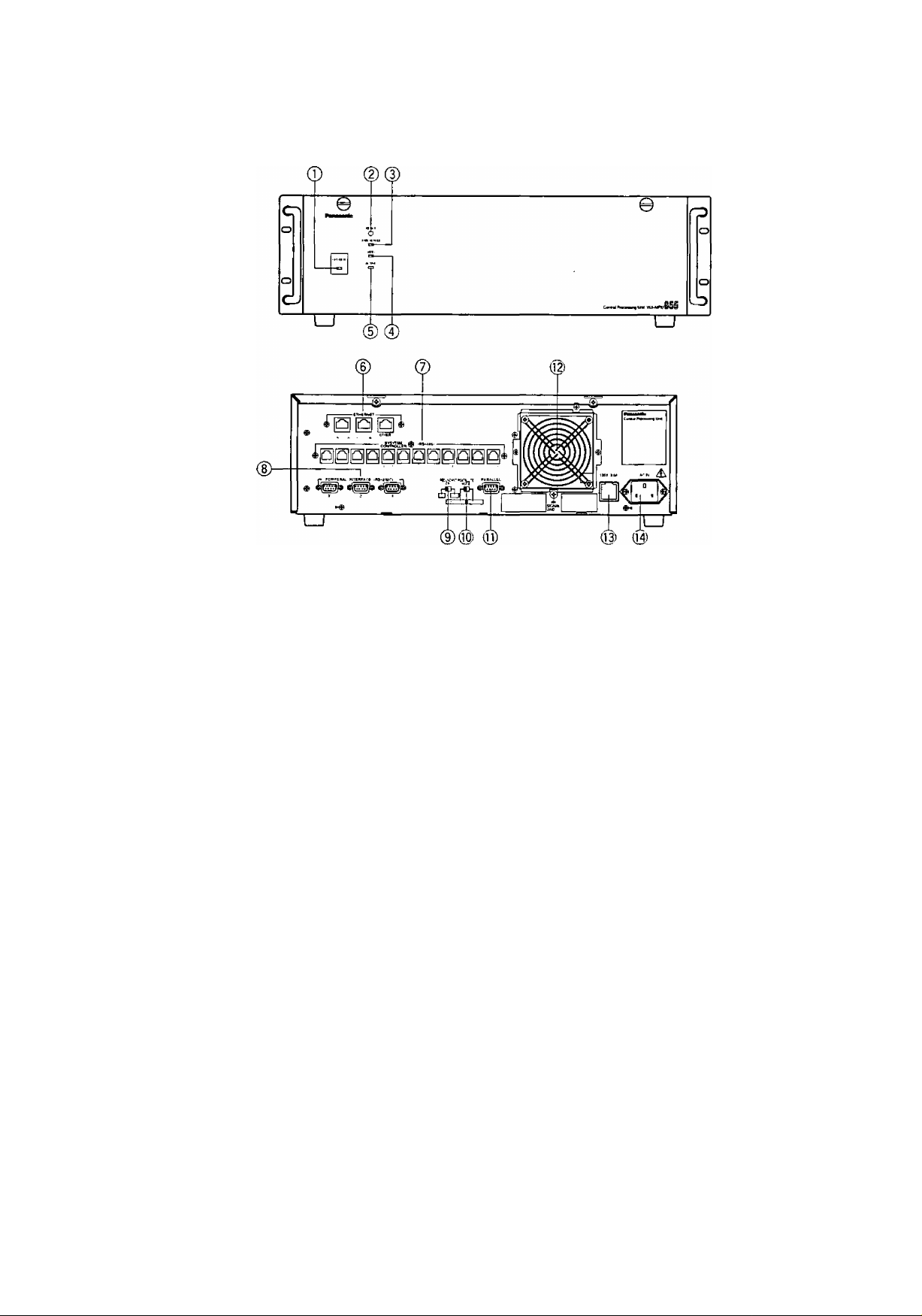
Front View
• Rear View
© Operate Indicator (OPERATE)
Is on when the power of the WJ-MPU855 CPU is
turned on.
Note: The power switch of the CPU is located
underneath the front panel,
Remove the front panel by removing two
screws on the panel.
@ Reset Button (RESET)
The RESET button is recessed inside the front panel
hole to the right of the OPERATE indicator.
Press this button when the CPU rejects control from
outboard equipment.
© Fan Alarm Indicator (FAN ALARM)
Indicates the cooling fan status.
This LED lights when a temperature rise in the CPU
is detected. Turn the power off and refer servicing
to qualified service personnel.
© HDD (Hard Disk Drive) Indicator (HDD)
Indicates the hard disk drive status.
© Active Indicator (ACTIVE)
Indicates the system status of the CPU,
® Ethernet Ports (ETHERNET)
Exchange control data via Ethernet.
• SYSTEM CONTROLLER
This port is provided for controlling the 850 System
with the WV-CU850 system controllers. Up to 64
controllers can be connected to this port through a
hub.
Note: The total number of system controllers con
nected via RS-485 and Ethernet is limited to 64.
• CAMERA/CROSS POINT/OSD
This port is used to exchange control data between
the cages through a hub.
• OTHER
Reserved for future use,
@ Controller Ports [SYSTEM CONTROLLER (RS-
485)]
These ports are provided for controlling the 850
System with the WV-CU350 system controllers. Up
to 12 controllers can be connected
® Peripheral Interface Ports [PERIPHERAL
INTERFACE (RS-232C)]
These ports are reserved for future use or factory
tests.
® Redundant CPU selector (REDUNDANT CPU)
Selects either a redundant system or a standalone
system.
The factory default setting is NO.
® Mode Selector (SATELLITE MODE)
Always keep in STANDALONE position.
® Parallel Port (PARALLEL)
This port is used to connect to the WJ-MPS855 CPU
Switch Unit for a redundant system.
(§) Cooling Fan Unit
Prevents the temperature of the CPU from rising.
Do not block the ventilation opening on the cover.
® Fuse Holder
O AC Inlet Socket (AC IN)
Plug the power cord (supplied as a standard
accessory) into this socket and connect it to an AC
-2-
outlet.
 Loading...