

Page 1
Digital Disk Recorder
WJ-HD316
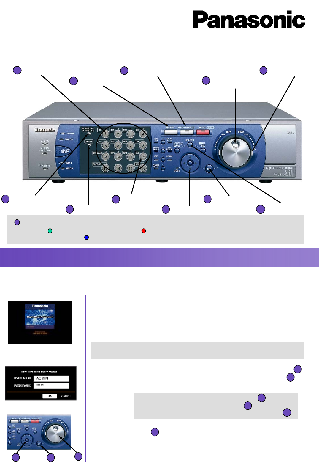
1
Camera Selection Buttons
2
STOP Button
6
Monitor Switch Button
7
SHIFT Button
3
PLAY/PAUSE Button
8
[12] Button
Quick Operation Guide
9
Arrow Button
4
Jog Dial
10
SET Button
5
Shuttle Ring
11
SEARCH Button
1
The Camera Selection Buttons change their color depending on the operation condition.
Startup
Startup
Startup splash image
Login window
Green: Camera live on monitor Orange: Camera under Recording
Blue: Camera live on monitor and under recording
(1) Insert the power plug to an outlet (make sure of the right
power source) and turn on the power switch on the rear panel.
• The OPERATE indicator will light and the system check will start. The startup
splash image to the left will be displayed on monitor 2 and VGA.
(2) Press any button on the front panel and the login window
will be displayed.
* When the auto login is on, live images will be displayed after the system
check. (Step 2 to 4 not required)
(3) Enter a user name and password by rotating the jog dial
to select a character and by pressing the arrow buttons
to move the cursor.
Cursor movement : Arrow button
Character input : Jog dial
Number input : Camera selection button
4
9
9
4
1
(4) Press the SET button to display a live image
• When authenticated, a live image will be displayed.
9
10
4
10
Page 2
Display
Display
Monitor of live images
(1) Press the MONITOR 1 / MONIT OR 2 button to select the monitor
(2)Press a camera selection button
Please check that the SHIFT button is not lit before pressing the camera selection button.
6
1
Live images from the selected camera will be displayed and the respective camera
selection button will light green or blue.
Monitor 1 : Display of live images only
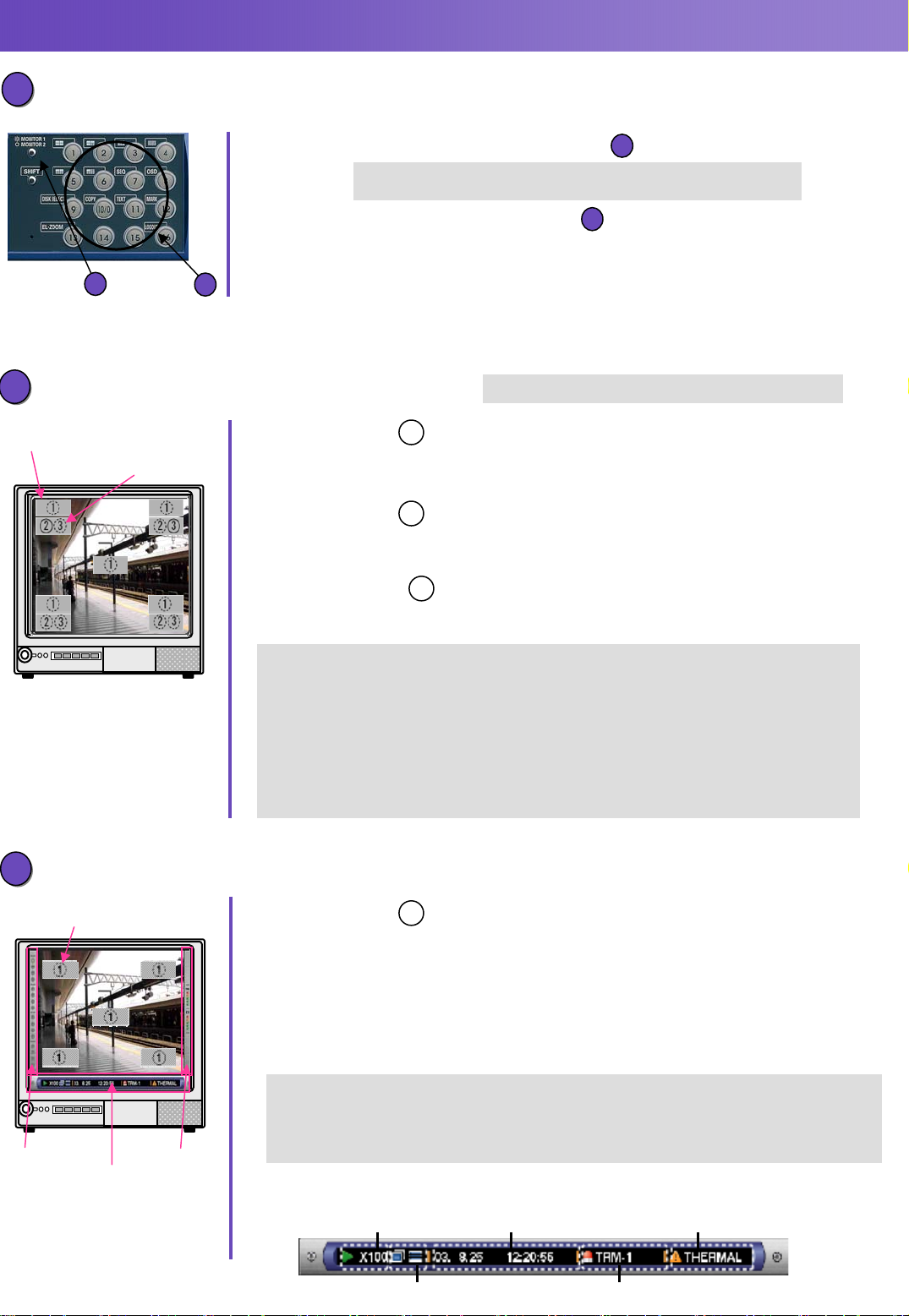
Camera Title Display
Time / Event Display
Camera title
● Camera Title
Displays the edited camera title.
Selectable positions: Upper left, upper right, lower left, lower right (Default), center.
● Time Display
Displays the current time and date.
Selectable positions: Upper left (Default), upper right, lower left, lower right, center.
● Event Display
Displays an alarm when an alarm occurred.
Selectable positions: Upper left, upper right (Default), lower left, lower right, center.
Event display depending on event.
6
When monitor 1 is selected the indicator will light.
When monitor 2 is selected the indicator will not light.
1
※The setup menu is displayed only on monitor 2.
1
2
3
VMD-* : When motion is detected by the motion detection function
LOSS-* : When video loss has occurred
COM-# : When a command alarm is supplied from a PC connected to the SERIAL
connector on the rear panel of this unit.
TRM-# : When a signal is supplied form an external device such as a door sensor
to the ALARM terminal.
(*: Camera number, #: Event
number)
Monitor 2, VGA Monitor: Display of live or recorded images (and setup menu)
1
the left and right bar.
Live/Playback Time
Display Area Error Display Area
Left bar
Camera Title
Main bar
● Camera Title
Displays the edited camera title.
Selectable positions: Upper left, upper right, lower left, lower right (Default), center.
● Task Bar
Displays the current status. The task bar consists of the main bar, the left bar and the
right bar. There are 3 different ways to display the task bar as follows.
Style 1: Displays only the main bar and the status is displayed on it.
Style 2: Displays the status on the main bar, the left bar and the right bar.
Style 3: Displays the status only on the main bar, and does not display information on
Right bar
■Status on the Task Bar
Status Display Area
Copy / Delete Icons Alarm Display Area
Page 3
Playback (1)
Playback (1)
1
Search and Play
1
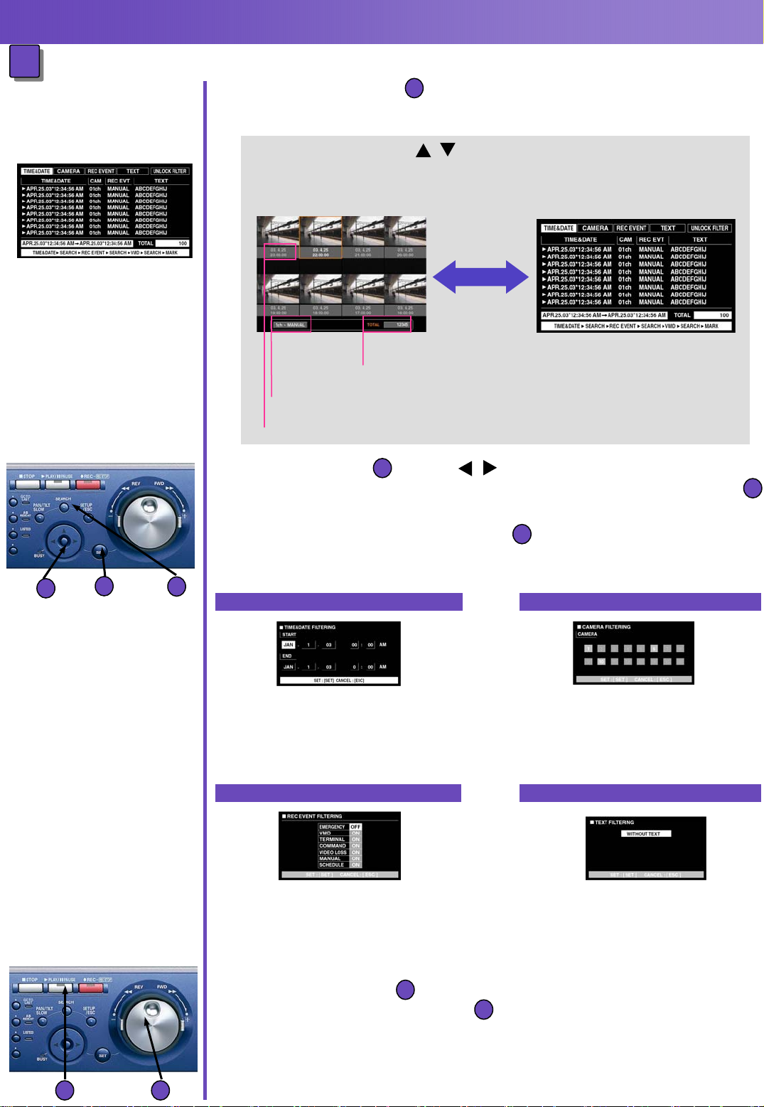
(1) Press the SEARCH button repeatedly until the recording
11
event list window is displayed.
Recording Event List Window
• Use the arrows button ( ) to switch displaying the list and the
thumbnail window alternately.
Recording Event Thumbnail Window
Display of the Number of the listed data.
Display of Camera channel of the recorded image and of the recording Mode.
Display of Time and Date when recording started.
(2)Use the arrows button ( ) to select a searching filter
9
Recording Event List Window
(TIME &DATE, CAMERA, EVENT, TEXT), press the SET button
When a searching filter is selected, the respective searching filter window will be displayed.
Select UNLOCK FILTER and press the SET button to cancel the selected filter.
10
10
(3) Filter recording events.
9
10
11
By time and date
Move the cursor using the arrows
button and rotate the jog dial to enter
time and date. Press the SET button
to determine the selection.
By recording event
Move the cursor to select the recording
event using the arrows button and rotate
the jog dial to ON. Press the SET button
to determine the selection.
By camera and channel
Select camera channel numbers
using the arrows button to apply
filtering and complete by pressing
the SET button.
By text information
Rotate the jog dial to select OFF,
WITH TEXT or WITHOUT TEXT.
Press the SET button to determine
the selection.
(4) Rotate the jog dial to select a recording event to be played
and press the PLAY/PAUSE button.
The LISTED indicator and the indicator on the PLAY/PAUSE button will light
and playback of the selected recording event will start.
43
4
3
Page 4

Playback (2)
Playback (2)
Searching for a marked point and play from that point
2
2
Note: Searching for a marked point, requires preliminary
setting of a mark at a replay position
Marking list window
● About Marking
・ Marking allows to “mark” a replay position for easier data retrieval.
・ Date and time of marked points are displayed on the marking list.
・ Up to 100 points can be marked. When more than 100 points are marked,
the oldest marked point will be overwritten by the new marked point.
・ When marked while displaying in multi-screen, the same numbers of split
screens will be counted as marked points.
(Marking on a 16-screen: 16points will be marked simultaneously)
(1) Press the PLAY/PAUSE button
3
7
8
to start playback
(2) Press the SHIFT button.
The SHIFT indicator will light.
(3) Press the camera selection button
[12] at a desired point to be
marked during playback.
8
7
3
11
(1) Press the SEARCH button repeatedly until the
marking list window is displayed.
(2) Rotate the jog dial to select a desired marked time
4
(3) Press the PLAY/PAUSE button
43
・The LISTED indicator and the indicator on the PLAY/PAUSE button will light,
and playback of the recorded image from the selected marked time will start.
11
1
3
Page 5

Useful Functions
Useful Functions
Multi Screen
1
1
(1) Press the [Monitor] Switch button to select the monitor
6
When monitor 1 is selected, the indicator will light
When monitor 2 is selected the indicator will not light
(2) Press the [Shift] button
7
6
1
(3) Press a camera selection button (1~6) to select
(4) To return to a single screen display press the SHIFT
Fast forward / Fast reverse
2
2
● Rotating the shuttle ring will change the playback speed.
7
・The SHIFT indicator will light
1
a desired multiscreen
Button 1: 4-split screen Button 2: 7-split screen
Button 3: 9-split screen Button 4: 16-split screen
Button 5: 10-split screen Button 6: 13-split screen
7
button. The SHIFT indicator will go off. Press any of the
camera selection buttons.
Clockwise rotating: fast forward
Counterclockwise rotating: fast reverse
1
5
3
3
10
Skip
• Depending on the degree of rotation the speed will change in 6 steps
(1/2x, 1x, 2x, 5x, 10x, 20x).
• When the shuttle ring is held in the 20x position for 5 sec.,
the playback speed will be 50x.
5
• When the shuttle ring held 5 more sec. after the playback speed became 50x,
the playback speed will be 100x.
• To play at normal speed, release the shuttle ring.
● Press the SET button while holding the rotated
shuttle ring to hold a desired playback speed.
• To return to the normal playback speed, press the SET button.
5
● Rotating the jog dial during playback will skip to the
10
4
next or previous recorded image and start playback
Clockwise rotating: skip to start time of next recording.
Counterclockwise rotating: skip to the start time of the previous recording.
4
• If there is no next or previous recorded image, current playback will continue.
Page 6

View images from PC
View images from PC
How to display the operation window
1
1
Browser window
(1) Start up the PC and the Web browser
(2) Enter the IP address set to this WJ-HD316
User authentication window
(3) Enter the user name and password registered on this
About the operation window
2
2
Status display area
Current status such us
playback status or recording
status will be displayed.
(Please use Internet Explorer 5.5 SP2 or 6.0)
in the address box and press the enter key.
unit and click on the LOGIN button
Current time/play time
display area
During live play display of
the current time.
During playback display of the
play time.
Control tab
The switcher
functions such
as switching
camera
channels or
displaying
sequentially,
are operable
on this page.
Search results
of log
information
will also be
displayed on
this page.
Setup tab
Operations for
setup of this
unit can be
performed on
this tab. Refer
to Network
Setup
Instructions for
further
information.
Image display area
Recorded images and live
images will be displayed.
The setup menu will be
displayed while setting up.
Playback point
operation area
It is possible to mark
playback points or skip to the
latest recorded image.
Camera tab
Controlling cameras by zooming, focusing and auto
panning can be performed on this page.
HDD tab
Operation for recorded images such as playback or
downloading (saving) recorded images can be
performed on this page.
Page 7

Troubleshooting
Troubleshooting
Before requesting repair check the Troubleshooting List
1
1
in the Operating Instructions
2
Error Messages
2
If one of the following error message is displayed, follow the instructions listed below.
Indication
ALT-*
SMART
H-METER
THERMAL
POWER
#-nn% (available disk space low)
#-FULL (no available disk space)
MEDIUM-n
Cause / Instructions
Recorder image has been altered. Playback will be paused.
Press the ALARM RESET button to cancel the error status.
Press the PLAY/PAUSE button to resume playback.
The hard disk may be malfunctioning and may not work correctly.
Press the ALARM RESET button to cancel the warning status.
Contact the dealer to replace th e h ar d disk.
The set time for the HOUR METER has passed.
It may be reaching the end of the hard disk’s lifetime.
Press the ALARM RESET button to cancel the warning status.
Contact the dealer to replace th e h ar d disk.
Thermal error of the unit or the optional extension unit has been detected.
Press the ALARM RESET button to cancel the warning status. If thermal errors occur
frequently, the unit may be malfunctioning. Contact the dealer.
The power outage alert signal is supplied from the UPS. When the internal processing
starts, recording will stop and all operations will be invalid.
Press the ALARM RESET button to cancel the warning status.
The unit will start operation automatically after the UPS start power supply.
The hard disk is almost full or completely full.
Press the ALARM RESET button to cancel the error or the warning status.
Initialize or replace the hard disk. When initialized, all recorded date will be deleted.
It is recommended to copy the data using an external recording device.
The external recording device is not operable bec a us e n o disk or different format disk has
been inserted, etc. Press the ALARM RESET button to cancel the warning status.
Confirm that a disk has been inserted, or check the inserted disk format.
An error has occurred on the hard disk and the hard disk has been unmounted from the
REMOVE
FAN
* : Camera number
# : Partition number
nn: Available disk space (percentage)
n : Port number to which an external recording device is connected
Digital Disk Recorder
system automatically.
Press the ALARM RESET button to cancel the error status. Contact the dealer.
The fan of this unit or the optional extension unit is malfunctioning. It may produce an
increase in temperature in the unit and cause malfunction of the HDDs.
The warning status will be canceled automatically after around 10 minutes of recovery.
Contact the dealer.
WJ-HD316 Home Page
Distributed by:
http://panasonic.co.jp/pss/hd300/en/index.html
CG040310 Version 1.0
 Loading...