

Page 1

–
+
TIMER
ERROR
ALARM
RESET
HDD 1
HDD 2
PULL
ALARM
ALARM
SUSPEND
OPERATE
Digital Disk Recorder
WJ-HD
316
A
M
O
N
IT
O
R
1
M
O
N
IT
O
R
2
SHIFT
DISK SELECT
EL-ZO
O
M
C
O
P
Y
TE
X
T
M
A
R
K
PAN
/
TILT
ZOO
M
/
FO
C
US
IRIS
LISTED
BUSY
A-B
R
EPE
AT
P
A
N
/TIL
T
S
LO
W
SETUP
/ESC
SEARCH
REV
FWD
SET
G
O
TO
LAST
PRESET
/AU
TO
LOGOUT
O
S
D
S
E
Q
1
4
7
8
9
11
12
13
14
15
16
10/0
5
2
6
3
- REC STOP
R
EC
-
S
T
O
P
P
A
U
S
E
P
LA
Y
Digital Disk Recorders
Network Operating Instructions
Model Nos. WJ-HD309A
WJ-HD316A
Before attempting to connect or operate this product,
please read these instructions carefully and save this manual for future use.
Page 2

2
Page 3

Contents
Preface ............................................................................................................................ 4
Features ...................................................................................................................... 4
Downloading/transmitting images ............................................................................... 4
Event notification function ........................................................................................... 4
Host authentication ..................................................................................................... 4
About these operating instructions .............................................................................. 4
System requirements for a PC .................................................................................... 5
Trademarks and registered trademarks ...................................................................... 5
Abbreviations .............................................................................................................. 5
About notations ........................................................................................................... 5
Display the operation window .......................................................................................... 6
How to display the operation window .......................................................................... 6
About the operation window ........................................................................................ 8
Adjust the clock ..............................................................................................................13
Recording/playback ......................................................................................................... 14
Recording (Manual recording) ..................................................................................... 14
Playback ...................................................................................................................... 16
Playback after selecting a disk ................................................................................... 19
Playback from a designated time and date ................................................................. 22
Search and play .......................................................................................................... 23
Monitor live images ......................................................................................................... 35
Display images from cameras on a single screen ....................................................... 35
Display images from cameras on a multi-screen ........................................................ 36
Display images in the sequential display .................................................................... 37
Control cameras .............................................................................................................. 38
Panning/tilting operation ............................................................................................. 38
Zooming ...................................................................................................................... 39
Focus adjustment ........................................................................................................ 40
Iris adjustment ............................................................................................................. 41
Move a camera to the preset position ......................................................................... 42
Auto function (Auto pan, etc) ....................................................................................... 43
Operating the camera setup menu .............................................................................. 44
About the event function ................................................................................................. 46
Action at an event occurrence .................................................................................... 46
Cancel the alarm action .............................................................................................. 48
Other functions ................................................................................................................49
Copying (Duplicate) ..................................................................................................... 49
Disk Management ....................................................................................................... 51
Deletion of recorded images saved on the hard disk manually ................................... 51
Format (initialize) a DVD-RAM disk ............................................................................ 54
Display/edit the text information .................................................................................. 58
Check logs .................................................................................................................. 59
Download recorded images ........................................................................................ 66
Play downloaded images ............................................................................................ 69
Save downloaded images ........................................................................................... 70
Print the displayed image ............................................................................................ 71
Perform the alteration detection .................................................................................. 71
Notification by e-mail ....................................................................................................... 73
Alarm mail notification ................................................................................................. 73
Warning mail notification ................................................................................................. 75
About error mail ...............................................................................................................76
Troubleshooting ............................................................................................................... 77
3
Page 4

Preface
Features
It is possible to perform the settings or operate the unit using a web browser installed on a PC when the WJHD316A/WJ-HD309A (this unit) is connected to a network.
The following functions are available when using a PC via a network as well as the functions operable using the buttons on the front panel of the unit.
Refer to the provided Operating Instructions for further information about the available functions.
Downloading/transmitting images
It is possible to download (save) the currently displayed image in the web browser window onto the hard disk of a
PC. By establishing an FTP server, it is possible to transmit images to a designated FTP server. When an event
occurs, it is possible to transmit images from the camera installed in the place where the alarm occurred.
Event notification function
When an event occurs, it is possible to send e-mails to designated addresses to notify of the event occurrence. It is
also possible to send an e-mail with an image recorded when an alarm occurred.
Host authentication
It is possible to restrict devices from operating this unit if their IP addresses are not registered.
About these operating instructions
There are 3 sets of operating instructions for the WJ-HD316A/WJ-HD309A as follows.
• Operating Instructions (book)
• Network Operating Instructions (PDF, these Operating Instructions)
• Network Setup Instructions (PDF)
These "Network Operating Instructions" contain descriptions of how to operate this unit using a PC via a network.
Refer to the provided "Operating Instructions (book)" for descriptions of how to operate this unit using the buttons on
the front panel of the unit.
Refer to the "Network Setup Instructions (PDF)" for descriptions of how to perform the required settings to operate
this unit using a PC and how to connect to other devices. (These operating instructions are for system installers.)
The settings of the unit will be different depending on the settings of a LAN or the Internet service provider to which
the unit is to be connected.
Adobe®Reader is required to read these operating instructions (PDF). When the Adobe®Reader is not installed on
the PC, download the latest Adobe®Reader from the Adobe web site and install it.
"WJ-HD300A" or "HD300A" written on the illustrations used in these operating instructions indicate this unit or the
WJ-HD300A series.
4
Page 5

System requirements for a PC
It is recommended to operate this unit using a PC that meets the following system requirements. If using a PC that
does not meet the following system requirements, it may cause problems such as slow imaging or the browser
becomes inoperable.
OS Microsoft®Windows®2000 Professional SP4
Microsoft®Windows®XP Professional or Home Edition SP1
Computer IBM PC/AT Compatible
CPU Pentium®4 1.4GHz or faster
Memory 512 MB or more
Monitor 1024 x 768 pixels or more, 16-bit HIGH color or better
Network Interface 10/100Mbps Network interface card must be installed
Web Browser Microsoft®Internet Explorer 5.5SP2, 6.0SP1
Other web browsers are not compatible with this unit.
Important:
To operate this unit, the plug-in software is required to be installed. The plug-in software will be downloaded and
installed automatically when accessing the unit using a browser. If the plug-in software has not been downloaded/installed correctly, install it from the provided CD-ROM. Refer to "readme.txt" on the provided CD-ROM
for the descriptions of how to install it.
Trademarks and registered trademarks
• Adobe, Adobe logos, and Acrobat are registered trademarks of Adobe Systems Incorporated in the U.S. and/or
other countries.
• Microsoft, Windows and Windows XP are registered trademarks of Microsoft Corporation in the U.S. and/or other
countries.
• Other names of companies and products contained in these operating instructions may be trademarks or registered trademarks of their respective owners.
Abbreviations
The following abbreviations are used in these operating instructions.
Microsoft
Microsoft®Windows®XP is described as Windows XP.
®
Windows®2000 Professional Service Pack 4 is described as Windows 2000.
About notations
Important: Restrictions or cautions to operate respective functions.
Note: Tips to operate respective functions.
5
Page 6
Display the operation window
How to display the operation window
Start up the PC and operate this unit using the installed web browser.
The operation window will be displayed in the following procedures.
Screenshot 1
Start just after the PC is started up.
Step 1
Start up the web browser.
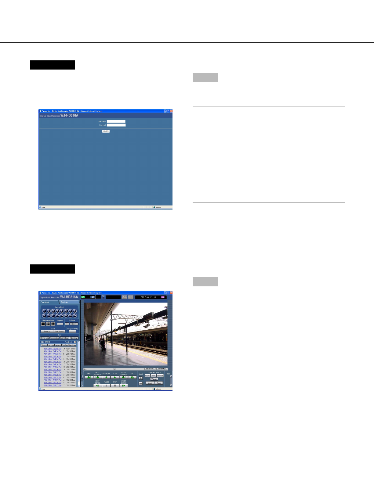
Screenshot 2
The web browser will start up and the set web site will
be displayed.
Step 2
Enter the IP address set to this unit in the address box,
and press the enter key.
Important:
• Refer to a system administrator for the set IP
address of this unit.
• It is impossible to access this unit from a PC without
a registered IP address when "ON" is selected for
"Host Authentication" on the " NW Setup 1" of
"Comm" menu.
Refer to a system administrator for further information.
• Do not attach "0" before the numbers when entering
IP address.
Example
Correct: 192.168.0.50
Wrong: 192.168.0.050
6
Page 7
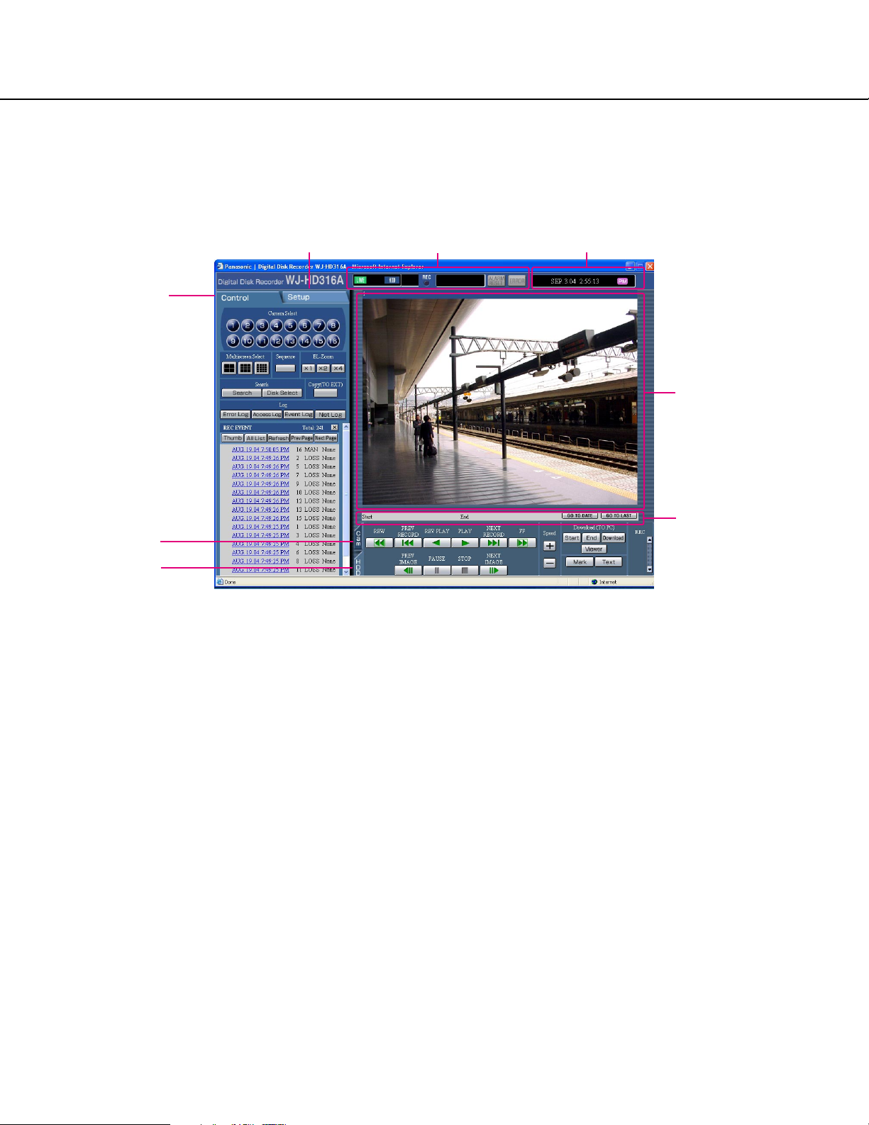
Screenshot 3
The user authentication window will be displayed. This
window will not be displayed when "OFF" is selected for
"User Authentication" on the "NW Setup 1" of "Comm"
menu.
Step 3
Enter the user name and password registered on this
unit.
Important:
• Refer to a system administrator for the set user
name and password.
Refer to the Network Setup Instructions (PDF) for
descriptions of how to register users.
• The default user name and password are as follows.
User Name: ADMIN
Password: 12345
• To enhance the security, change the password for
an administrator before running the unit. Refer to the
Network Setup Instructions (PDF) for descriptions of
how to change the password.
Screenshot 4
The top page will be displayed.
Step 4
Click the buttons or the tabs for operations.
7
Page 8
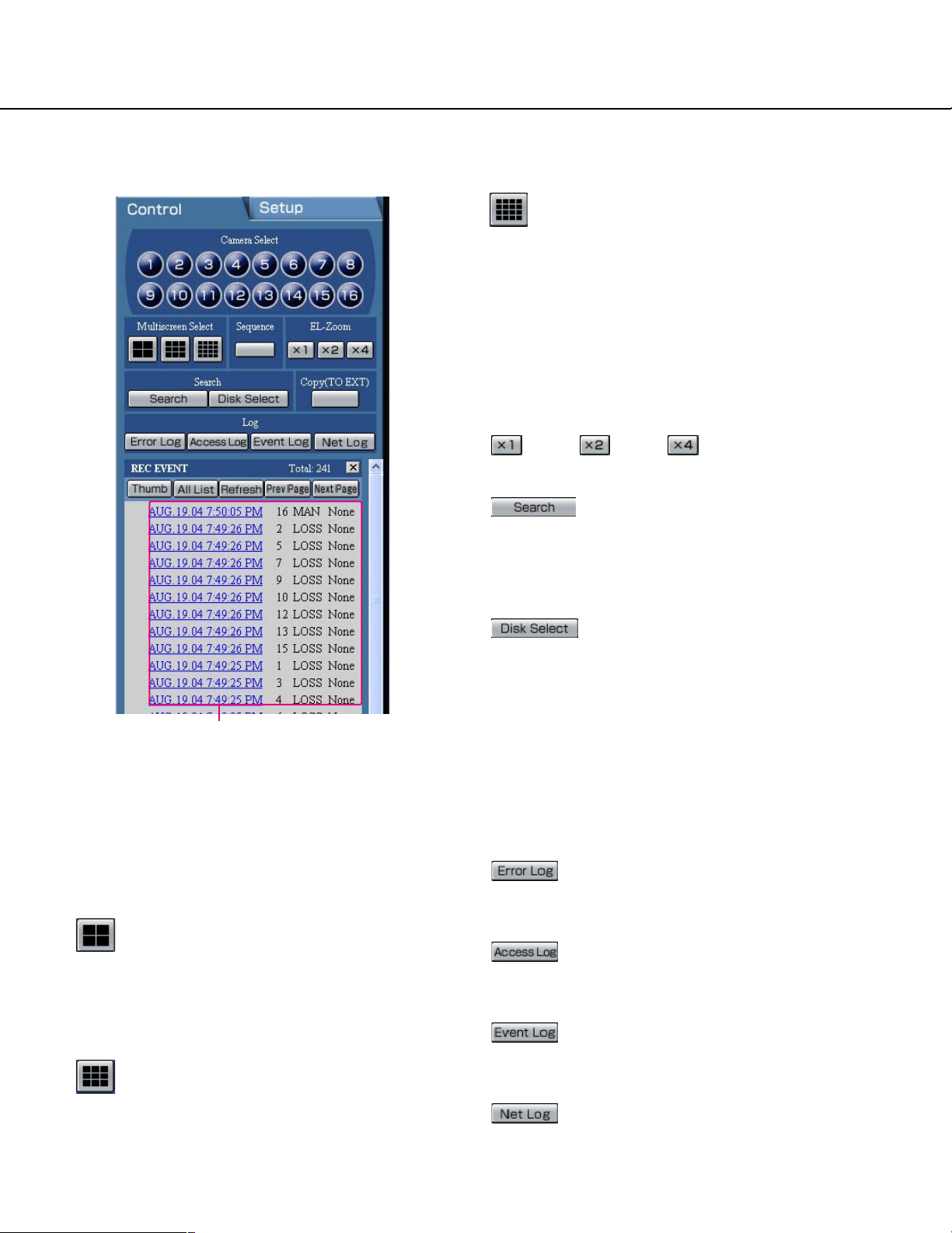
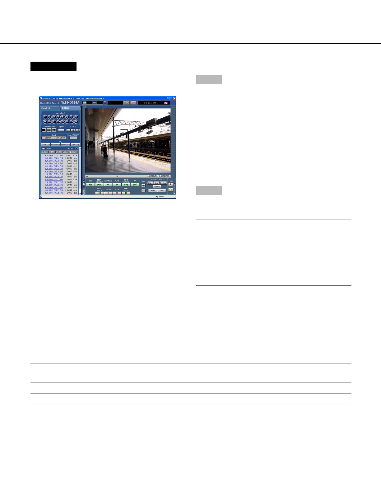
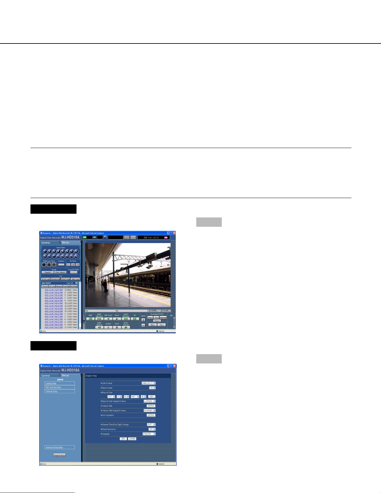
About the operation window
Top page
[Setup] tab Status display area Current time/recorded time displayed area
[Control] tab
[Cam] tab
Image display area
Playback point
operation area
[HDD] tab
[Control] tab (page 9)
The switcher functions such as switching camera channels or displaying them sequentially, are operable on
this page. Search results or log information will also be
displayed on this page.
[Setup] tab
Operations for setup of this unit can be performed on
this tab. Refer to the Network Setup Instructions (PDF)
for further information.
Using the setup menu (Quick) and the setup
menu (Advanced)
First, check the settings items of the setup menu
(Quick) and perform the settings. When more
detailed settings are required, perform the settings
on the setup menu (Advanced).
Refer to the Network Setup Instructions (PDF) for
descriptions about the setup menu (Advanced).
Status display area (page 10)
Current status such as playback status or recording status will be displayed.
Current time/recorded time displayed area
When monitoring live images, the current time will be
displayed. When playing recorded images, the recorded
time and date will be displayed.
Image display area
Recorded images and live images will be displayed. The
setup menu will be displayed while setting up.
Playback point operation area (page 11)
It is possible to mark playback points or skip to the latest recorded image.
[HDD] tab (page 11)
Operation for recorded images such as playback or
downloading (saving) recorded images can be performed on this page.
[Cam] tab (page 12)
Controlling cameras by zooming, focusing and auto
panning can be performed on this page.
8
Page 9
[Control] tab
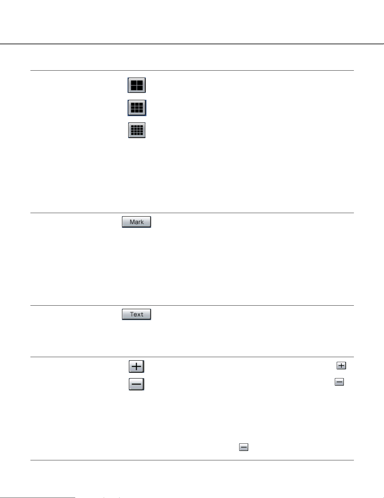
16-split screen (Only for the WJ-HD316A):
Images from 1 - 16 channels will be displayed on
a 16-split screen.
[Sequence] box
Camera images to be displayed will be switched by
clicking this button. Camera images will be displayed
sequentially according to the settings performed in
advance.
[EL-Zoom] box
Camera images will be displayed in the proportion of the
clicked zoom ratio button.
: 1x : 2x : 4x
[Search] box
[Search] button: The "SELECT SEARCH"
pop-up window will be displayed.
Use this button to search the recorded images and
play them. (Refer to page 25.)
Search results will be displayed in list form in the log
display area. (Refer to page 24.)
[Disk Select] button: The "DISK
SELECT" pop-up window will be displayed. Use this
button to select a disk to be played/searched. (Refer
to page 19.)
Log display area
[Camera Select] box
Images from the selected camera channel will be displayed on the image display area by clicking one of
these buttons.
[Multiscreen Select] box
Up to 16 camera images can be displayed simultaneously on a multi-screen.
4-split screen button: 4 camera images will be
displayed on a 4-split screen in the following
order each time this button is clicked;
For the WJ-HD316A: 1 - 4 CH → 5 - 8 CH
→ 9 - 12 CH → 13 - 16 CH → 1 - 4 CH ...
For the WJ-HD309A: 1 - 4 CH → 5 - 8 CH → 9 CH
→ 1 - 4 CH ...
9-split screen button: 9 camera images will be
displayed on a 9-split screen in the following
order each time this button is clicked;
For the WJ-HD316A: 1 - 9 CH → 10 - 16 CH
→ 1 - 9 CH...
For the WJ-HD309A: 1 - 9 CH
[Copy (TO EXT)] box
The copy window will be displayed by clicking this button. Use this when manually copying recorded images
onto the copy area of the hard disk or external recording
devices (DVD-RAM disk, DVD-R disk, CD-R disk).
[Log] box
[Error Log] button: The error logs of this
unit will be displayed.
Logs will be displayed in list form in the log display
area. (Refer to page 59.)
[Access Log] button: The time when logged
in/out for this unit, the user name, and the IP address will be displayed. Logs will be displayed in list
form in the log display area. (Refer to page 62.)
[Event Log] button: The event logs (event
occurrence times and their details) will be displayed.
Logs will be displayed in list form in the log display
area. (Refer to page 63.)
[Net Log] button: The network error logs will
be displayed. Logs will be displayed in list form in
the log display area. (Refer to page 64.)
9
Page 10
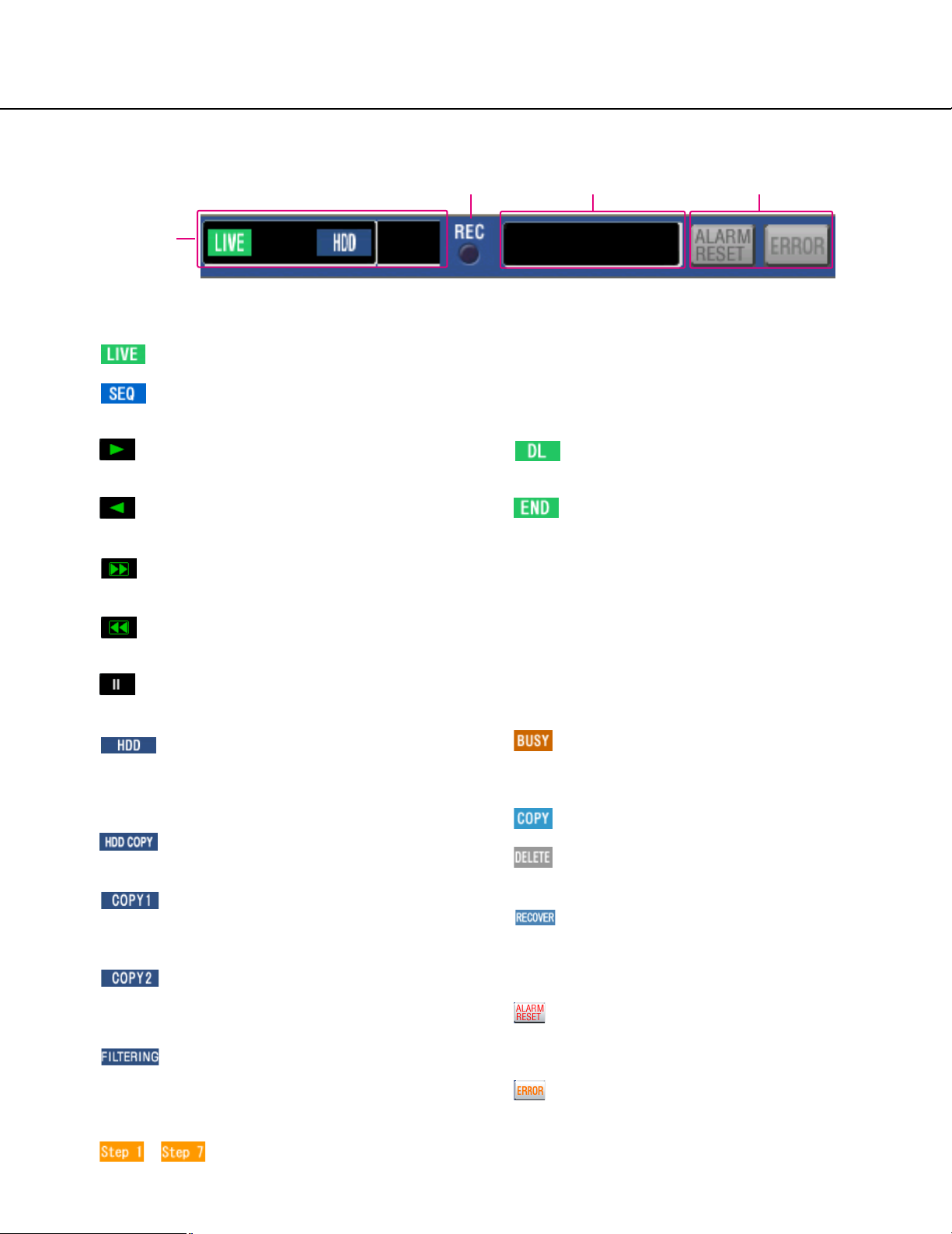
Status display area
q
w e r
q The status of live/playback image will be
displayed.
[LIVE]:
Indicates that a live image is being displayed.
[SEQ]:
Indicates that a live image is being displayed in
the sequential display mode.
[Playback]:
Indicates that a playback image is being displayed.
[Reverse playback]:
Indicates that a reverse playback image is being
displayed.
[Fast playback]:
Indicates that a fast playback image is being displayed.
[Fast reverse playback]:
Indicates that a fast reverse playback image is
being displayed.
[Pause]:
Indicates that a paused image is being displayed.
[HDD]:
Indicates that playback of a recorded image
stored in the normal recording area or the event
recording area of the built-in hard disk of this unit
is currently being selected.
[HDD COPY]:
Indicates that the HDD copy area is currently
being selected.
[COPY1]:
Indicates that the external recording device connected to the COPY1 port is currently being
selected.
[COPY2]:
Indicates that the external recording device connected to the COPY2 port is currently being
selected.
[FILTERING]:
Indicates that the recording event list/thumbnail
is filtered.
Refer to 22 for further information about filtering
of the recording event list.
– [Step1] – [Step7]:
Indicates the playback speed.
Step1: Normal playback speed
Step2: Approx. 4x playback speed
Step3: Approx. 8x playback speed
Step4: Approx. 16x playback speed
Step5: Approx. 32x playback speed
Step6: Approx. 48x playback speed
Step7: Approx. 96x playback speed
[DL]:
Indicates that the playback images are currently
being downloaded.
[END]:
Indicates that download of the playback images
has ended.
w REC indicator
The status of recording will be displayed.
When lit red:
Indicates that recording is being performed.
When not lit:
Indicates that recording is not being performed.
e Indicates the following statuses:
[BUSY]:
Indicates that the camera is not operable
because a user with higher priority is currently
operating that camera.
[COPY]:
Indicates that copying is being performed.
[DELETE]:
Indicates that deletion of a recorded image is
being performed.
[RECOVER]:
Indicates that mirror/RAID recovery is currently
being performed
r Indicates information about events and errors.
[ALARM RESET]:
Indicates an event occurrence.
The alarm display action will be canceled by
clicking this button. (page 47)
[ERROR]:
Indicates an error occurrence.
Refer to the provided operating instructions for
further information about error action.
10
Page 11

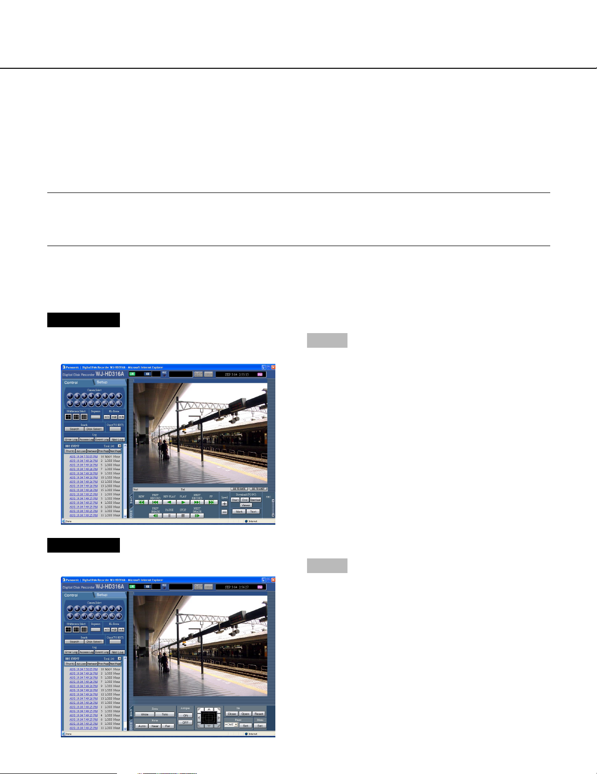
Playback point operation area
q
q Indicates the start time and the end time of a download. (Refer to page 66.)
w [GO TO DATE] button
Indicates the time and date of a marked point. Use this button to designate the desired time and date of a recorded image to be played. (Refer to page 22.)
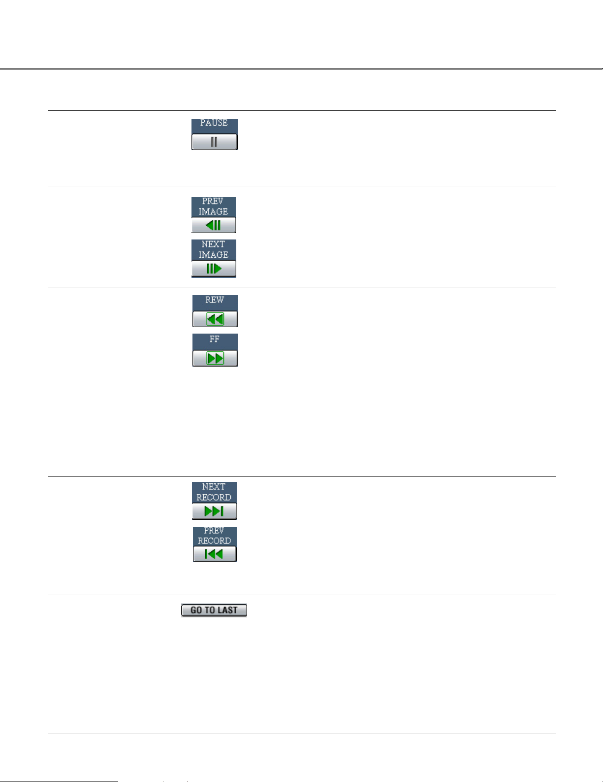
e [GO TO LAST] button
Skips to the latest recorded time of a recorded image from the currently displayed camera channel and plays it.
w e
[HDD] tab
[REW] button
Fast reverse playback will be performed. Playback
speed for fast reverse playback will be changed in the
following order each time this button is clicked: Step2
(approx. 4x) → Step3 (approx. 8x) →
Step4 (approx. 16x) → Step5 (approx. 32x) →
Step6 (approx. 48x) → Step7 (approx. 96x)
[PREV RECORD] button
Skips to the previous recorded image and plays it.
[REV PLAY] button
Reverse playback of a recorded image will be performed.
[PLAY] button
Playback of a recorded image will be performed.
[NEXT RECORD] button
Skips to the next recorded image and plays it.
[FF] button
Fast playback will be performed. Playback speed for
fast playback will be changed in the following order
each time this button is clicked:
Step2 (approx. 4x) → Step3 (approx. 8x) →
Step4 (approx. 16x) → Step5 (approx. 32x) →
Step6 (approx. 48x) → Step7 (approx. 96x)
[PREV IMAGE] button
The previous frame will be displayed when this button is
clicked during pausing.
[PAUSE] button
Playback will be stopped when this button is clicked during playback. Playback will be resumed when this button is clicked during pausing.
[STOP] button
Stops playback and displays a live image.
[NEXT IMAGE] button
The next frame will be displayed when this button is
clicked during pausing.
[Speed] button
The refresh interval will be shortened/lengthened by
clicking these buttons during playback.
11
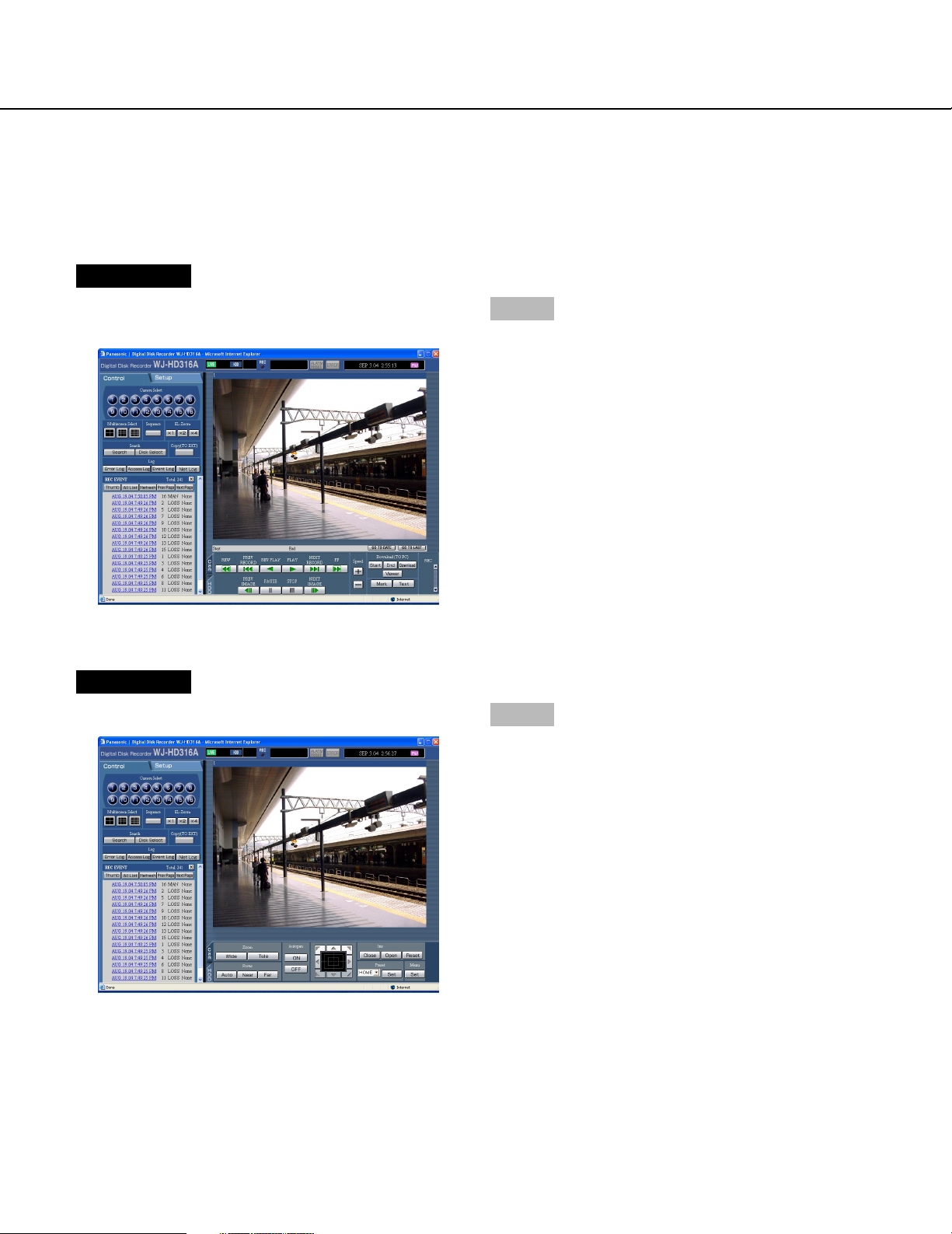
Page 12
[Download (TO PC)] box
Downloads the image currently playing to a PC.
Sets the time range of the desired image to be downloaded by clicking the [Start] button and the
[End] button.
The start time and the end time for download will be displayed in the playback point operation area.
The dialog window for saving an image to be downloaded onto a designated location will be displayed by
clicking the [Download] button.
[Viewer] button
The viewer software can be downloaded by clicking this
button.
[Mark] button
Mark by clicking this button during playback. When
marked, playback after searching for the marked point is
available. (Refer to pages 18 and 31.)
[Text] button
The attached text information will be displayed when
this button is clicked during pausing. It is possible to edit
the displayed text information.
[REC] box
The recording button and the recording stop button will
be displayed when the button is clicked.
Displaying the recording button and the recording stop
button will be unavailable when the button is clicked.
[Recording] button: Starts manual recording.
[Stop recording] button: Stops manual
recording.
Notes:
• It is possible to select whether to switch between all
channels, or to select the channel currently displayed in the web browser window to be selected for
manual recording, by performing the settings.
• To display the [Recording] button and the [Stop
recording] button, hold down the button until they
are displayed.
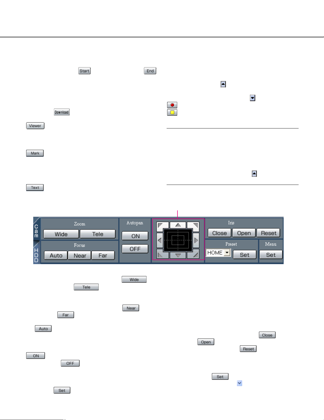
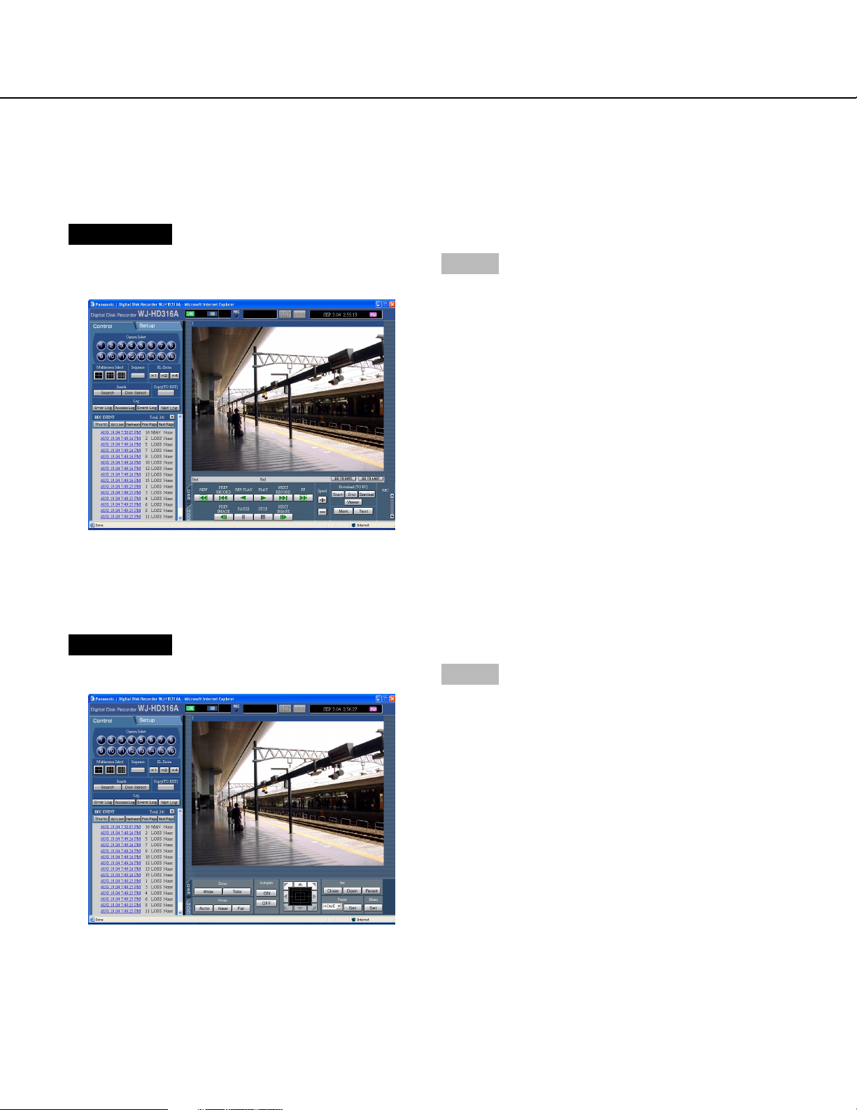
[Cam] tab
[Zoom] box
Zooming can be adjusted by clicking the
[Wide] button or the [Tele] button.
[Focus] box
Focusing can be adjusted by clicking the [Near]
button or the [Far] button.
The auto focus function can be performed by clicking
the [Auto] button.
[Autopan] box
The auto function of the camera will start by clicking the
[ON] button. The auto function can be stopped
by clicking the [OFF] button.
[Menu] box
The settings menu of the camera will be displayed by
clicking the [Set] button.
Control pad
Control pad/buttons
Clicking the buttons around the control pad can move
(pan/tilt) a camera in the clicked direction.
Clicking inside the control pad also can adjust the vertical/horizontal position (pan/tilt) of the displayed image.
Panning/tilting speed will be faster if a clicked point gets
farther from the center point of the control pad.
[Iris] box
The iris can be adjusted by clicking the [Close]
button or the [Open] button. It is possible to
reset the set iris by clicking the [Reset] button.
[Preset] box
Moves a camera to the preset position registered in
advance. Click the [Set] button after selecting a
preset number by clicking the button.
Registering preset positions is required to perform the
preset function.
12
Page 13

Adjust the clock
Adjust the clock of this unit to the correct time. Check the clock periodically and adjust the clock if it shows the wrong
time.
Note:
The following are the descriptions of how to adjust the clock on the setup menu (Quick).
Refer to the Network Setup Instructions (PDF) for descriptions of how to adjust the clock on the setup menu
(Advanced).
Screenshot 1
Start operation from the top page.
Step 1
Click the [Setup] tab.
Screenshot 2
The setup menu (Quick) will be displayed.
Step 2
Set the time and date by clicking the [i] buttons of
"Time & Date".
Step 3
Click the [SET] button on the right side.
→ The set time and date will be applied.
13
Page 14

Recording/playback
Recording (Manual recording)
Start/stop recording manually.
Refer to a system administrator for the required settings for manual recording.
Screenshot 1
Start operation from the top page.
Step 1
Click the [HDD] tab.
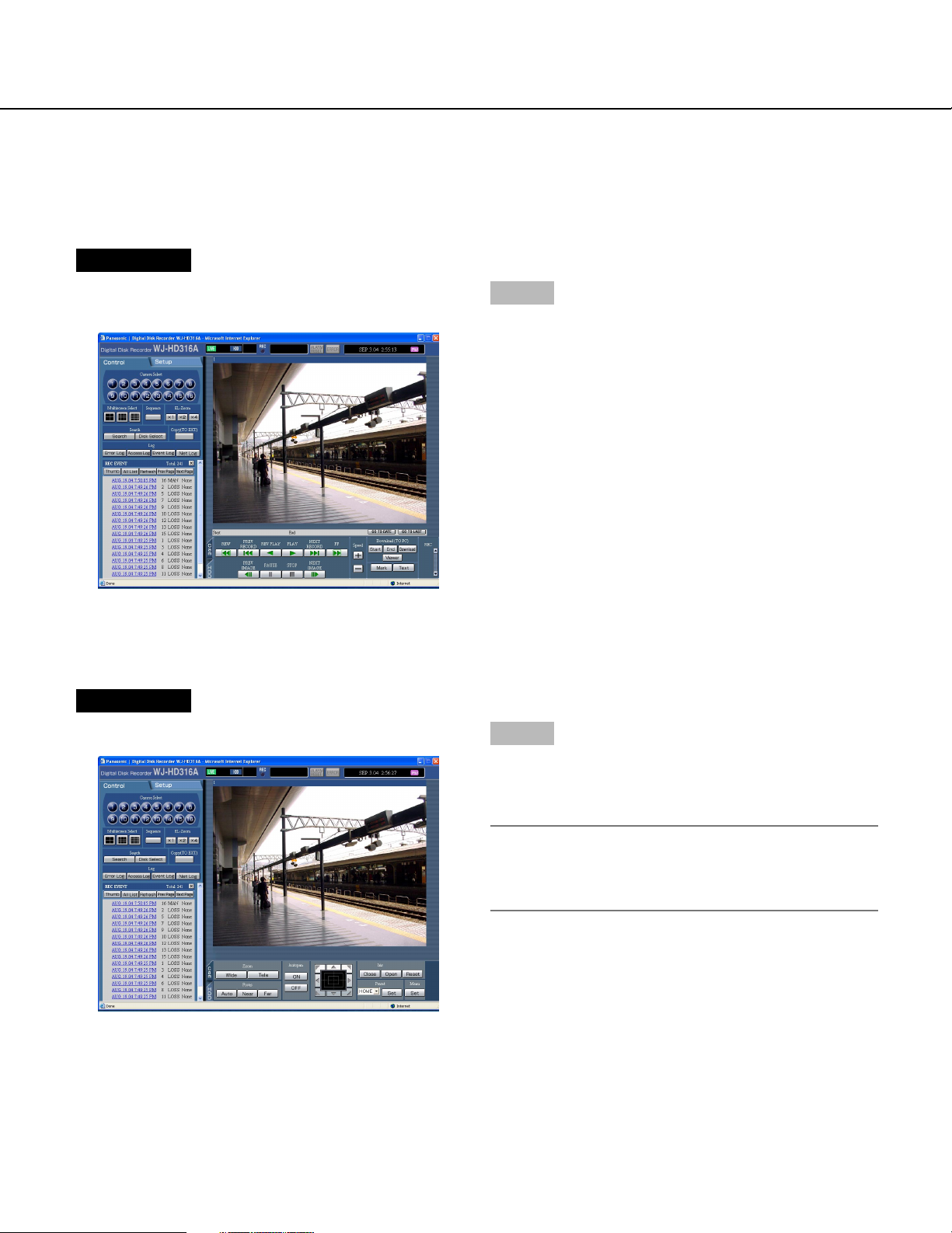
Screenshot 2
The [HDD] page will be displayed.
Step 2
Click the [D] button of the [REC] box.
Note:
Hold down the [D] button until the [Recording] button and the [Stop recording] button are displayed.
14
Page 15
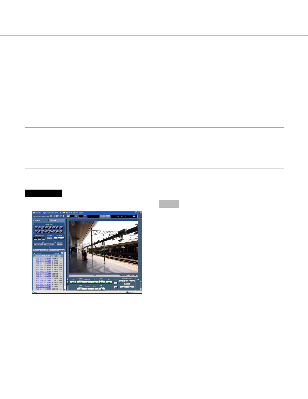
Screenshot 3
The [Recording] button will be displayed in the [REC]
box.
Step 3
Start recording by clicking the [Recording] button.
• The REC indicator in the status display area will be
lit red when recording has started.
• Images from all cameras connected to this unit will
be recorded with the default settings.
• When images from cameras are currently recorded
with higher priority than manual recording, manual
recording will be suspended until that recording finishes.
Refer to the following for further information about
each recording mode.
Step 4
Click the [Stop recording] button to stop recording.
→ The REC indicator will go off.
Notes:
• The REC indicator will continue to be lit when
recording in the other recording mode even though
the [Stop recording] button is clicked.
• When a video input signal supply stops during manual recording, recording will also stop automatically.
When the video input signal supply resumes, recording will also resume automatically.
About the recording mode and the priority
There are 4 recording modes. Each recording mode and priority is as follows.
Recording Mode Description Priority
Emergency recording When an emergency event occurs, perform recording manually using
an external switch, etc..
Event recording Perform recording manually at any event occurrence.
Manual recording Start/stop recording manually.
Schedule recording It is possible to perform recording automatically at a scheduled time on
a designated day of a week.
*1: These priorities are the default settings. (Emergency recording is the highest priority.)
*2: It is possible to change the priority for manual recording, schedule recording and event recording. Refer to a sys-
tem administrator for further information.
Highest
*1
*2
1
*2
2
*2
3
15
Page 16

Playback
Play recorded images. Playback is also available during recording.
Screenshot 1
Start operation from the top page.
Screenshot 2
The [HDD] page will be displayed.
Step 1
Click the [HDD] tab.
Step 2
Click the [PLAY] button.
→ Playback of a recorded image will be performed.
When played for first time after logon:
Except for the settings above:
will be displayed in the status display area.
The latest recorded image will be played.
Playback will start 5 seconds before the time of
the latest recorded image with the default setting.
The following are available for the playback start
time.
5 s/10 s/30 s/1 min/5 min
Refer to a system administrator for further information.
Playback will start from the finish point (time and
date) of the last playback.
16
Notes:
• It is possible to change the camera channel by clicking the desired [Camera Select] button during playback.
• It is possible to switch the screen to a multi-screen
by clicking the desired [Multiscreen Select] button
during playback
Step 3
Click the [STOP] button to stop playback.
→ displayed in the status display area will go off
and a live image will be displayed.
Page 17
Other functions for playback
Pausing • Playback will be stopped when this button is clicked during
playback.
• Playback will be resumed when this button is clicked during
pausing.
Frame play/reverse
frame play
Fast playback/fast
reverse playback
• Frame play/reverse frame play is available only during pausing.
• When the [NEXT IMAGE] button is clicked, the next frame is
played and paused.
• When the [PREV IMAGE] button is clicked, the previous
frame is played and paused.
• Playback speed for fast playback will be changed in the following order each time the [FF] button is clicked: Step2
(approx. 4x) → Step3 (approx. 8x) → Step4 (approx. 16x) →
Step5 (approx. 32x) → Step6 (approx. 48x) → Step7
(approx. 96x)
• Playback speed for fast reverse playback will be changed in
the following order each time [REW] button is clicked: Step2
(approx. 4x) → Step3 (approx. 8x) → Step4 (approx. 16x) →
Step5 (approx. 32x) → Step6 (approx. 48x) → Step7
(approx. 96x)
• When the [PLAY] button or the [REV PLAY] button is clicked
during fast playback/fast reverse playback, playback speed
will return to the normal playback speed.
Skip/reverse skip
Skips to the latest
recorded image.
• When the [NEXT RECORD] button is clicked, playback is
skipped to the latest recorded image.
• When the [PREV RECORD] button is clicked, playback is
skipped to the oldest recorded image.
• When there is no latest/oldest recorded image to be skipped
to, the current playback will continue, but the playback may
start from a point around a minute before the last playback
point.
• Skips to the latest time of the image currently playing and
plays it. Skips to the point 5 seconds before the time of the
latest recorded image with the default setting.
The following points are available to be skipped to.
5s/10 s/30 s/1 min/5 min
Refer to a system administrator for further information.
When the [GO TO LAST] button is clicked while displaying
live images, playback of the latest recorded images from the
selected camera channel will start.
17
Page 18
Playback on a multiscreen
• Displays playback images on a 4-split screen, 9-split screen
or 16-split screen (only for the WJ-HD316A).
• 4 camera images will be displayed on a 4-split screen in the
following order each time this button is clicked;
For the WJ-HD316A: 1 - 4 CH → 5 - 8 CH → 9 - 12 CH
→ 13 - 16 CH → 1 - 4 CH ...
For the WJ-HD309A: 1 - 4 CH → 5 - 8 CH → 9 CH
→ 1 - 4 CH ...
• 9 camera images will be displayed on a 9-split screen in the
following order each time this button is clicked;
For the WJ-HD316A: 1 - 9 CH → 10 - 16 CH → 1 - 9 CH...
For the WJ-HD309A: 1 - 9 CH
• Images from channels 1 - 16 will be displayed on a 16-split
screen (only for the WJ-HD316A).
• Click a camera channel button in the [Camera select] box to
return to a single screen display.
Marking
(Refer to page 31 for
operation.)
Text information
display
Image Refresh Interval
Adjustment
• It is possible to start playback from a marked point.
Click the [Mark] button at the point to be marked.
• Up to 100 points can be registered. When more than 100
points are marked, the older marked points will be overwritten
by newly marked points. In this case, the oldest point is the
first to be overwritten.
• During playback in a multi-screen, the point when the [Mark]
button is clicked for all played images will be registered. (The
number of the points for all played images in a multi-screen
will be registered simultaneously.)
• The attached text information will be displayed when this button is clicked during pausing.
Click the [Text] button after pausing playback.
• The text information display/edit is available only when a
recorded image is played in a single screen.
• The image refresh intervals will be shorter each time the
button is clicked.
• The image refresh intervals will be longer each time the
button is clicked.
18
Notes:
• The image refresh intervals can be adjusted only when playing recorded images on a single screen.
• When playing the images recorded with a low recording rate,
playback speed may be too fast. In this case, adjust the
speed by clicking the button.
Page 19

Playback after selecting a disk
Images from cameras will be recorded on the built-in hard disk or external recording devices (DVD-RAM disk, DVDR disk, CD-R disk). Select a disk and play images as follows.
The following disks can be selected.
• HDD normal recording area/event recording area: Recording area in the built-in hard disk of this unit. Recorded
images by manual recording (page 14) or event recording will be stored in this area.
There are 3 ways to search for a recorded image and play it when "HDD normal area" or "event recording area"
is selected as the recording area.
• Search for a recording event and play it (Recording event search) (page 23)
• Search for a motion detected time and date from the recorded images and play it (VMD search) (page 27)
• Search for a marked point and play from that point (Marking search) (page 31)
• HDD copy area: Recording area in the built-in hard disk of this unit. Recording area for copying recorded images.
There are 2 ways to search for a recorded image and play it when "HDD copy area" is selected as the recording
area.
• Search for a recording event and play it (Recording event search) (page 23)
• Search for a motion detected time and date from the recorded images and play it (VMD search) (page 27)
• COPY1/COPY2: Recording area in the external recording device (DVD-RAM disk, DVD-R disk, CD-R disk) connect-
ed to the COPY1 port or the COPY2 port of the unit. Recording area for copying recorded images.
To search for a recorded image when "COPY1" or "COPY2" is selected as the recording area.
• Search for copy data (Copy Data Search) (page 33)
Built-in hard disk (HDD)
Recording area for manual recording/normal recording
Normal recording area
Recording area for event recording
Event recording area
Recording area for copying
Copy area
Notes:
• The built-in hard disk or external recording device is described as "disk" in these operating instructions.
• Playback is also available during recording.
• When a pre-recording area is created in an optional extension unit (WJ-HDE300 series), it is possible to play the
images recorded on the pre-recording area.
• The capacity of each recording area will be different depending on the settings. Refer to a system administrator
for further information.
19
Page 20

Screenshot 1
Start operation from the top page.
Screenshot 2
The [DISK SELECT] window will be displayed.
Step 1
Click the [Disk Select] button in the [Search] box of the
[Control] tab.
Step 2
Check the radio button of the desired disk to be played.
Step 3
Click the [OK] button.
Note:
It is impossible to select the HDD copy area, COPY1
and COPY2 in the following cases (the pop-up window will be displayed):
• When the selected area has been selected by
another user
• When copying is being performed manually in
the selected area
• When the selected area is set as the copy area
for the auto copy function
Step 4
Click the [HDD] tab.
20
Page 21

Screenshot 3
The [HDD] page will be displayed.
Step 5
Click the [PLAY] button.
→ Recorded images on the selected disk will be
played. will be displayed in the status display
area.
Note:
Playback will start from the finishing point (time and
date) of the last playback by clicking the [PLAY] button after stopping playback.
Step 6
Click the [STOP] button to stop playback.
→ in the status display area will go off.
21
Page 22

Playback from a designated time and date
Start playback by designating the desired time and date of a recorded image to be played. Playback is also available
during recording.
Note:
This feature is available only when "HDD normal area", "event recording area" or "HDD copy area" is selected as
the recording area.
Screenshot 1
Start operation from the top page.
Step 1
Click the [GO TO DATE] button in the playback position
operation area.
Screenshot 2
The "GO TO DATE" menu will be displayed.
Step 2
Click the [i] button and enter the desired time and
date of a recorded image to be played.
Step 3
Click the [PLAY] button.
→ Play recorded images of the entered time and date.
will be displayed in the status display area.
When there is no image for the entered time and
date, the following action will be taken.
When there are images recorded after the entered
time and date, the oldest recorded image after the
entered time and date will be played.
When there is no image recorded after the entered
time and date, the latest recorded image before the
entered time and date will be played.
Step 4
Click the [STOP] button to stop playback.
→ in the status display area will go off.
22
Page 23

Search and play
Search for the desired recorded image and play it.
The 4 ways to search are as follows.
• Search for a recording event and play it (Recording event search) (page 23)
• Search for a motion detected time and date from the recorded images and play it (VMD search) (page 27)
• Search for a marked point and play from that point (Marking search) (page 31)
• Search for copy data (Copy Data Search) (page 33)
The available "search and play" methods are different depending on the selected recording area as follows.
When "HDD normal area" or "event recording area" is selected as the recording area
• Recording event search (page 23)
• VMD search (page 27)
• Marking search (page 31)
When "HDD copy area" is selected as the recording area
• Recording event search (page 23)
• VMD search (page 27)
When "COPY1" or "COPY2" is selected as the recording area
• Copy Data Search (page 33)
Note: Recorded images will be played in a single screen on monitor 2 and the VGA monitor. Click the 4-split screen
button, the 9-split screen button or the 16-split screen button to display in a multi-screen.
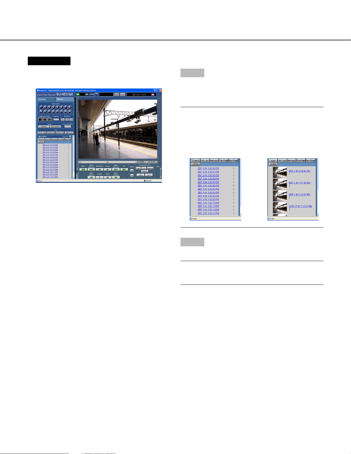
Search for a recording event and play it (Recording event search)
Display a list or thumbnails of recording events and select the desired one to be played.
This feature is available only when "HDD normal recording area", "event recording area" or "HDD copy area" is set
as the recording area. When "COPY1" or "COPY2" is selected, this feature is not available.
Recording events can be searched by filtering as follows.
About filtering
Conditions for filtering How to search
Time and date Designate a time period and search images recorded in the designated period to
play.
Camera channel Searches for images from the selected camera channel only.
Event Searches for images from the selected recording mode only. The following
recording modes can be selected.
• Manual: Manual recording (Refer to page 14.)
• Schedule: Schedule recording (Refer to the provided Operating
Instructions for further information.)
• Emergency: Emergency recording (Refer to the provided Operating
Instructions for further information.)
• Video Loss: Recording performed at a video loss (Refer to page 46.)
• VMD: Recording performed by a motion detection function
(Refer to page 46.)
• TRM: Recording triggered by a terminal alarm (Refer to page 46.)
• COM: Recording triggered by a command alarm (Refer to page 46.)
Text Searches only images recorded with text information.
23
Page 24
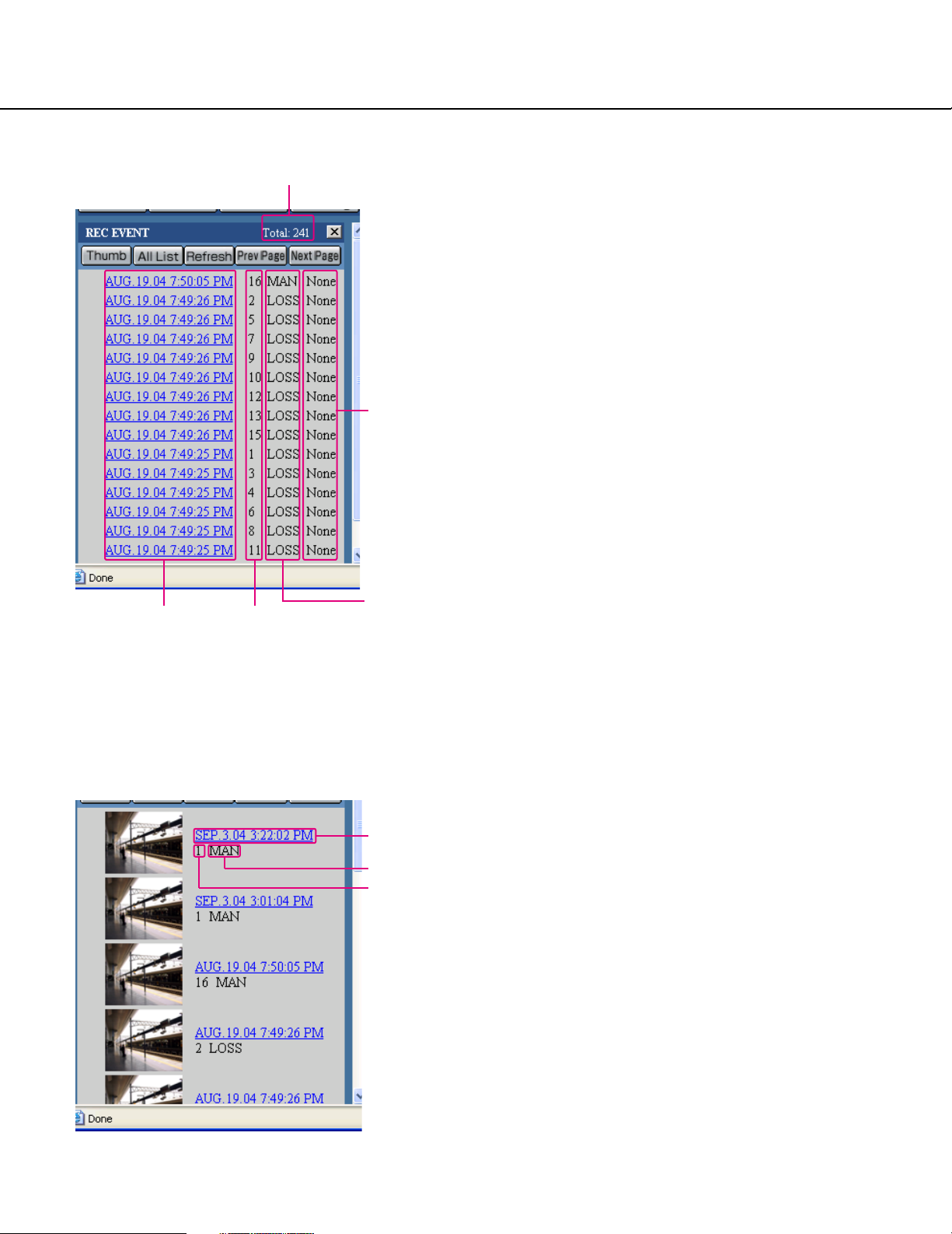
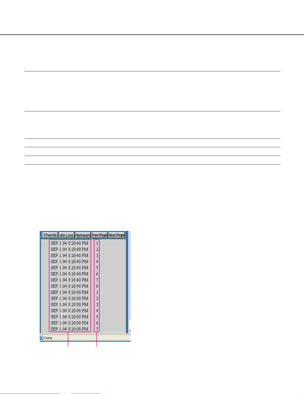
About displaying the recording event list window
Number of the listed data
Text
Time Camera
channels
Number of the listed data: Displays the total number
of the listed data
[Thumb] button: Switches to the thumbnail display
shown below.
Event
[All List] button: Cancels filtering and lists all recording
events.
[Refresh] button: Refreshes the displayed contents to
the newest one.
[Prev Page] button: Displays the previous page of the
list.
[Next page] button: Displays the next page of the list.
Time: <When using the recording event search list>
Start time of recording will be displayed.
<When using the VMD search>
The time when motion was detected will be displayed.
<When using the marking search>
The time of the marked point will be displayed.
Camera channels: A camera channel currently used
for recording will be displayed. Recorded images of
the displayed camera channel will be played in a single screen.
Event: Recording mode will be displayed.
MAN: Manual recording
SCH: Scheduled recording
EMR: Emergency recording
LOSS: Recording at a video loss occurrence
VMD: Recording at a motion detection
TRM: Recording at a terminal alarm occurrence
COM: Recording at a command alarm occurrence
Text: When text information is attached to the recorded
image, "Added" will be displayed. When text information is not attached to the recorded image,
"None" will be displayed.
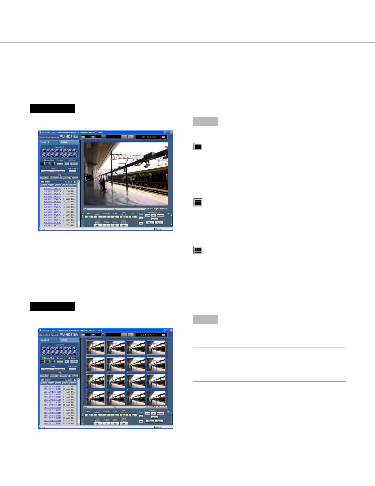
About the recording event thumbnail window
24
Time
Event
Camera
channels
[List] button: Switches to the list display shown above.
[All List] button: Cancels filtering and lists all recording
events.
[Refresh] button: Refreshes the displayed contents to
the newest one.
[Prev Page] button: Displays the previous page of the
thumbnail.
[Next Page] button: Displays the next page of the
thumbnail.
Time: <When using the recording event search list>
Start time of recording will be displayed.
<When using the VMD search>
The time when motion is detected will be displayed.
<When using the marking search>
The time of the marked point will be displayed.
Camera channels: A camera channel currently used
for recording will be displayed. Recorded images of
the displayed camera channel will be played in a single screen.
Event: Recording mode will be displayed.
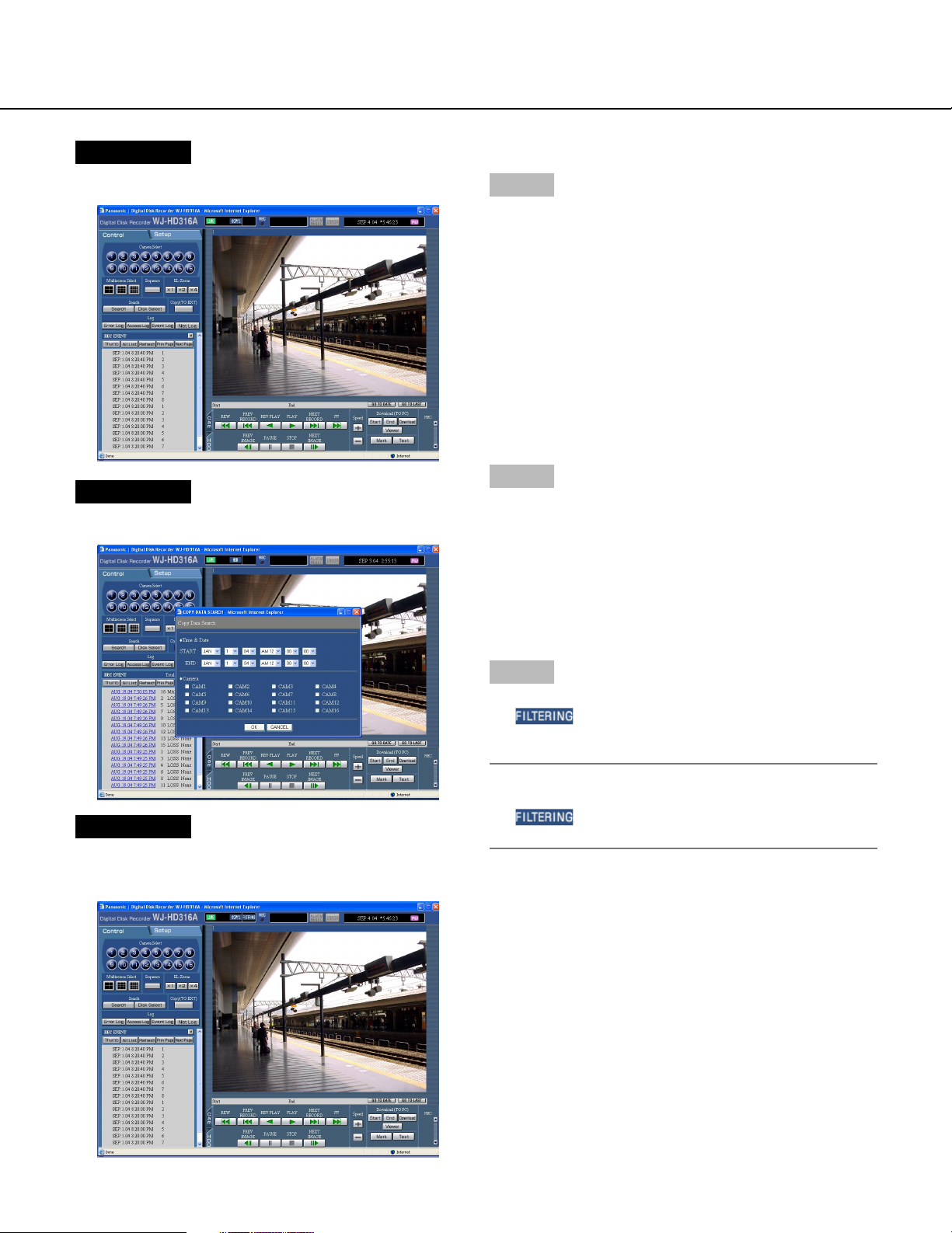
Page 25
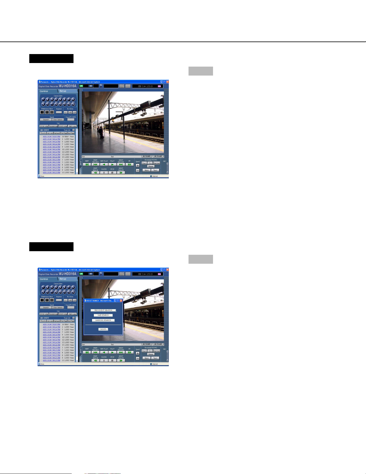
Screenshot 1
Start operation from the top page.
Step 1
Click the [Search] button in the [Search] box of the
[Control] tab.
Screenshot 2
The [SELECT SEARCH] window will be displayed.
Step 2
Click the [REC EVENT SEARCH] button.
25
Page 26

Screenshot 3
The [REC EVENT SEARCH] window will be displayed.
Step 3
Select searching conditions
• Filter by time and date
Select a start time and an end time by clicking the
[i] button.
• Click to select the desired recording event to be displayed when filtering by recording events.
• Filter by camera channel
Click to select the desired camera channel to be displayed.
• Filter by with/without text information
Select "Added" or "None" by clicking the [i] button.
When "--" is selected, searching will be performed
without filtering by with/without text information.
Step 4
Click the [OK] button.
→ will be displayed in the status display area.
The filtered result will be displayed.
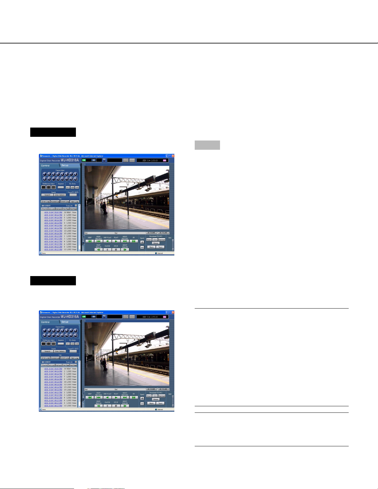
Screenshot 4
The search results (recording event list) will be displayed in the log display area.
Note:
Click the [All List] button to cancel the filtering.
will go off and all recording events will be
listed.
Step 5
Click the time of the desired recording event.
→ Play a recorded image of the recording event from
the selected time.
Note:
It is possible to switch to the recording thumbnail
window (page 24) by clicking the [Thumb] button.
⇔
26
Step 6
Click the [STOP] button to stop playback.
Page 27
Search for a motion detected time and date from the recorded images and play it
(VMD search)
Searches time and date when motion was detected from recorded images in all the recording modes (page 15) and
displays them in the list or the thumbnail window. Select the desired time and date from the search result list or
thumbnail and play it. It is possible to filter time and date when motion is detected by the detection sensitivity or the
searching mode.
Note:
Recorded images will be played in a single screen. Click any of (the 4-split screen button), (the 9-split
screen button) or (the 16-split screen button) to display in a multi-screen.
This feature is available only when "HDD normal recording area", "event recording area" or "HDD copy area" is
set as the recording area. When "COPY1" or "COPY2" is selected, this feature is not available.
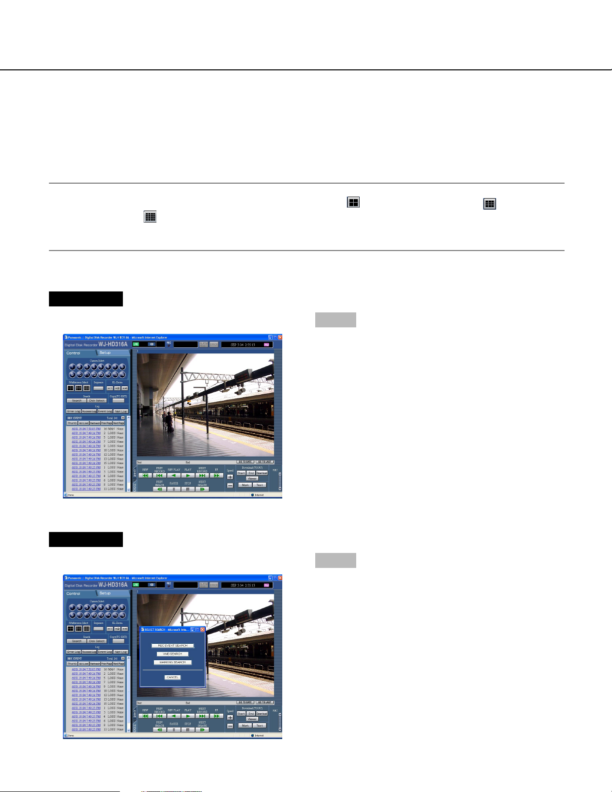
Screenshot 1
Start operation from the top page.
Step 1
Click the [Search] button in the [Search] box of the
[Control] tab.
Screenshot 2
The [SELECT SEARCH] window will be displayed.
Step 2
Click the [VMD SEARCH] button.
27
Page 28

Screenshot 3
The [VMD SEARCH 1] window will be displayed.
Step 3
Click the [i] button to designate a time period and
camera channels for the VMD search.
Step 4
Click the [OK] button.
Screenshot 4
The [VMD SEARCH 2] window will be displayed.
Step 5
Set the motion detection areas by dragging the mouse.
Up to 4 areas (A, B, C, D) can be set for the detection
areas.
A: White
B: Blue
C: Green
D: Red
Click the [SET ALL AREA] button to set all areas on the
monitor as the motion detection area.
To delete a detection area, click the [DELETE AREA]
button after selecting a detection area by checking the
check box of the desired area to be deleted.
Step 6
Press the [i] button to select sensitivity for the selected area from the following.
HIGH: High sensitivity
MID: Intermediate sensitivity
LOW: Low sensitivity
OFF: Ignores motion in the selected area
28
Step 7
Perform the settings for the detection mode. It is possible to set how motion is detected in the motion detection
area by performing the settings for each detection
mode.
Select the desired detection mode and perform the settings for each detection mode independently. Refer to
page 30 for further information about the detection
mode.
Page 29

<ANY AREA>
Click the [i] button to select a mask period from
the following.
1 s/1 min/1 h/24 h
Step 8
Click the [OK] button.
→ Searching will start.
<VECTOR>
Click the [i] button to select an interval time for an
object moving between each area from the following.
--/5 s/10 s/20 s/30 s/40 s/50 s/1 min
<DURATION>
Click the [i] button to select a moving duration for
an object from the following.
0 s/5 s/10 s/20 s/30 s/40 s/50 s/1 min
Screenshot 5
The search results (recording event list) will be displayed below the [Control] tab.
Notes:
• It may take time until the search results are displayed.
• The [STOP] button will be displayed in the corresponding area during searching. It is possible to stop
searching by pressing the [STOP] button.
Step 9
Click a time of the desired recording event.
→ Images of the selected recording event time will be
played.
STEP10
Click the [STOP] button to stop playback.
Note:
It is possible to switch to the recording thumbnail
window (page 24) by clicking the [Thumb] button.
⇔
29
Page 30

Detection mode
The three detection modes are as follows.
Important:
Activating two or more detection modes simultaneously is not possible.
<ANY AREA mode>
An event action will be performed according to the settings when "motion" is detected in any of the set motion detection areas.
A B
Any motion will be detected anywhere in the A, B, C, D areas.
C D
<VECTOR mode>
An event action will be performed according to the settings when an object moves within the set time to the other
detection areas in the set order.
The following is an example.
10 s
A B
20 s
C D
10 s
Motion is detected in area B within 10 seconds after being detected in area A.
Motion is detected in area C within 20 seconds after being detected in area B.
Motion is detected in area D within 10 seconds after being detected in area C.
When all of the above have occurred, an event action will be performed.
<DURATION mode>
An event action will be performed according to the settings when an object keeps on moving for the set period in the
detection area. For example, in case of the following settings; 10 sec. for areas A and B, 20 sec. for area C and 30
sec. for area D:
An event action will be performed when an object keeps on moving for more than
A
10 s
C
20 s
B
10 s
D
30 s
the set period in the specified detection area.
Important:
• When images to be searched are recorded with a low recording rate, the
DURATION mode may not work correctly.
• It may take time to search according to the contents of the recorded images.
30
Page 31

Search for a marked point and play from that point (Marking search)
Display the recording time of recorded images with a marked point in a list or a thumbnail and select the desired
recording time to play. Refer to page 18 for further information about marking.
Note:
Recorded images will be played in a single screen. Click any of (the 4-split screen button), (the 9-split
screen button) or (the 16-split screen button) to display in a multi-screen.
This feature is available only when "HDD normal recording area" or "event recording area" is set as the recording
area. When "HDD copy area", "COPY1" or "COPY2" is selected, this feature is not available.
Screenshot 1
Start operation from the top page.
Step 1
Click the [Search] button in the [Search] box of the
[Control] tab.
Screenshot 2
The [SELECT SEARCH] window will be displayed.
Step 2
Click the [MARKING SEARCH] button.
31
Page 32
Screenshot 3
The search results (recording event list) will be displayed below the [Control] tab.
Step 3
Click the time when the point was marked to play.
→ Play a recorded image from the selected marked
time.
Notes:
• It is possible to switch to the thumbnail window
(page 24) by clicking the [Thumbnail] button.
• It is possible to switch to the list window by clicking
the [List] button when the thumbnail window is displayed.
⇔
Step 4
Click the [STOP] button to stop playback.
Note:
To delete all the marked points, click the [All Del]
button.
32
Page 33
Search for copy data (Copy Data Search)
Display a list or thumbnails of copy data.
Copy data can be searched by filtering as follows.
Notes:
• This feature is available only when "COPY1" or "COPY2" is set as the recording area. When "HDD normal
recording area", "event recording area" or "HDD copy area" is selected, this feature is not available.
• If the copy completion is not performed for the CD-R/DVD-R disk, it is impossible to search copied recorded
images on the CD-R/DVD-R disk.
Refer to the operating instructions (book) for further information about the copy completion.
About filtering
Conditions for filtering How to search
Time and date Designate a time period and search images recorded in the designated period.
Camera channel Searches for images from the selected camera channel only.
About displaying the copy data list window
[Thumb] button: This button is not available for the
copy data search.
[All List] button: Cancels filtering and lists all recording
events.
[Refresh] button: Refreshes the displayed contents to
the newest one.
[Prev Page] button: Displays the previous page of the
list.
[Next page] button: Displays the next page of the list.
Time and date: Start time of recording will be dis-
played.
Camera channels: A camera channel used for record-
ing of copy data will be displayed.
Time and date Camera
channels
33
Page 34
Screenshot 1
Start operation from the top page.
Screenshot 2
The [COPY DATA SEARCH] window will be displayed.
Step 1
Click the [Search] button in the [Search] box of the
[Control] tab.
Step 2
Select searching conditions
• Filter by time and date
Select a start time and an end time by clicking the
[i] button.
• Filter by camera channel
Click to select the desired camera channel to be displayed.
Screenshot 3
The search results (copy data list) will be displayed in
the log display area.
Step 3
Click the [OK] button.
→ will be displayed in the status display area.
The filtered result will be displayed.
Note:
Click the [All List] button to cancel the filtering.
will go off and all copy data files will be list-
ed.
34
Page 35
Monitor live images
Live image will be displayed.
It is possible to display live images on a single screen or a multi-screen.
It is also possible to display live images sequentially (sequential display).
Display images from cameras on a single screen
Screenshot 1
Start operation from the top page.
Step 1
Select the desired camera channel to display live
images.
Click the desired camera channel button in the [Camera
Select] box of the [Control] tab.
Screenshot 2
Live images from the selected camera channel will be
displayed.
About the electrical zoom
When displaying an image on a single screen,
zooming in on the displayed image is possible.
Click the button in the [EL-Zoom] box to zoom in on
the displayed image.
[x1] button: Returns to the original displayed size (x1
zoomed size).
[x2] button: Displays images with x2 zoomed size.
[x4] button: Displays images with x4 zoomed size.
Clicking a point in the zoomed image moves the
zoomed image by positioning the clicked point as
the center point.
Note:
When the [GO TO LAST] button is clicked while displaying live images, playback of the latest recorded
images from the selected camera channel will start.
35
Page 36
Display images from cameras on a multi-screen
Displays images on the 4-split screen, 9-split screen or 16-split screen (only for the WJ-HD316).
Screenshot 1
Start operation from the top page.
Step 1
Click the desired multi-screen button in the [Multiscreen
Select] box of the [Control] tab.
4-split screen button: 4 camera images will be displayed on a 4-split screen in the following order
each time this button is clicked;
For the WJ-HD316A: 1 - 4 CH → 5 - 8 CH
→ 9 - 12 CH → 13 - 16 CH → 1 - 4 CH ...
For the WJ-HD309A: 1 - 4 CH → 5 - 8 CH → 9 CH
→ 1 - 4 CH ...
9-split screen button: 9 camera images will be displayed on a 9-split screen in the following order
each time this button is clicked;
For the WJ-HD316A: 1 - 9 CH → 10 - 16 CH
→ 1 - 9 CH...
For the WJ-HD309A: 1 - 9 CH
16-split screen button (Only for the WJ-HD
316A): Displays images from camera channels 1 -
16 on a 16-split screen.
Screenshot 2
Live images will be displayed in a multi-screen.
36
Step 2
Click a camera channel button in the [Camera Select]
box to return to a single screen display.
Note:
When the [GO TO LAST] button is clicked while displaying live images, playback of the latest recorded
images from the selected camera channel will start.
Page 37

Display images in the sequential display
Displayed images from cameras will be switched automatically.
Camera images will be displayed sequentially according to the settings performed in advance.
Screenshot 1
Start operation from the top page.
Step 1
Click a button in the [Sequence] box of the [Control] tab.
Screenshot 2
Live images will be displayed sequentially according to
the settings performed in advance.
Step 2
To stop the sequential display, click the button once
again.
When operations to display images on a single screen
(page 35) or multi-screen (page 36) are performed during the sequential display, the sequential display will be
canceled.
Notes:
• Cameras that are out of controllable range set by the
camera partitioning function will be skipped. Refer to
the Network Setup Instructions (PDF) for further
information about the camera partitioning.
• When the [GO TO LAST] button is clicked while displaying live images, playback of the latest recorded
images from the selected camera channel will start.
37
Page 38
Control cameras
When displaying live images, the following camera controls are possible.
• Panning/tilting: Moves a camera horizontally/vertically.
• Zooming: Zooms in/out of images.
• Focus: Adjusts the focus.
• Iris: Adjusts the iris of the lens.
• Preset action: Moves a camera to the preset position registered in advance.
• Auto function: Moves a camera with an auto function set in advance.
• Camera setup: Performs camera settings.
Notes:
• Depending on the models of the connected cameras, it may be impossible to control the camera or some functions may be not available.
• Controlling cameras is possible only when displaying live images on a single screen.
Panning/tilting operation
Moves a camera horizontally/vertically.
Screenshot 1
Panning and tilting are possible only when displaying
live images on a single screen.
Step 1
Click the [Cam] tab.
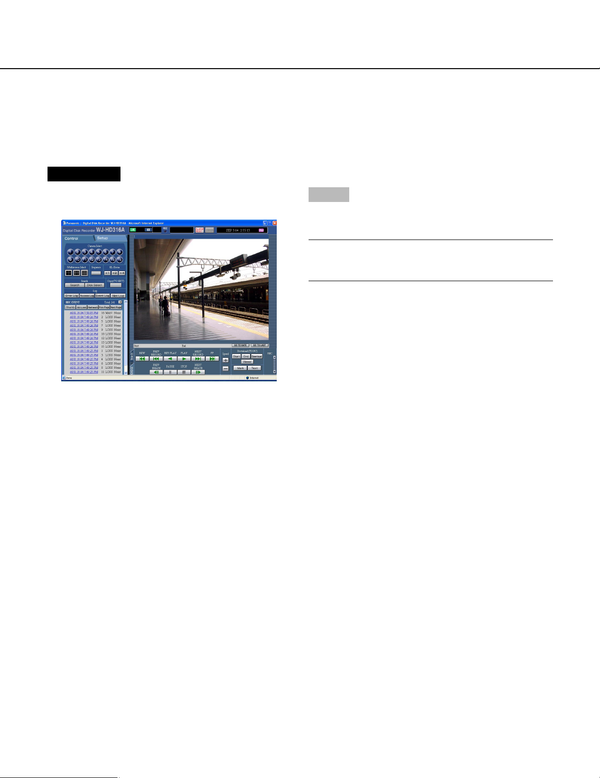
Screenshot 2
The [Cam] tab will be displayed.
38
Step 2
Moves a camera horizontally/vertically in the following
ways.
• Control buttons: Click to move the camera.
• Control pad: Click to move the camera. Panning/tilt-
ing speed will be faster if a clicked point gets farther
from the center point of the control pad.
• Image display area: Click the desired point to be
the center of the field angle in the displayed image.
The camera moves to position the clicked point as
the center point of its image.
Page 39
Zooming
Zooms in/out of images. Depending on the models of the connected cameras, the image size for the respective
zooming portion may be different. For further information, refer to the operating instructions for the camera.
Screenshot 1
Start operation when a live image is displayed on a single screen.
Step 1
Click the [Cam] tab.
Screenshot 2
The [Cam] tab will be displayed.
Step 2
Adjust zooming by clicking the [Wide] button or the
[Tele] button in the [Zoom] box.
39
Page 40

Focus adjustment
Adjusts the focus. The auto focus function is available.
Screenshot 1
Start operation when a live image is displayed on a single screen.
Step 1
Click the [Cam] tab.
Screenshot 2
The [Cam] tab will be displayed.
Step 2
Adjust the focus by clicking the [Near] button or the [Far]
button in the [Focus] box.
The auto focus function is available by clicking the
[Auto] button.
40
Page 41
Iris adjustment
Adjusts the iris of the lens.
Screenshot 1
Start operation when a live image is displayed on a single screen.
Step 1
Click the [Cam] tab.
Screenshot 2
The [Cam] tab will be displayed.
Step 2
Adjust the iris by clicking the [Open] button or the
[Close] button in the [Iris] box.
Click the [Reset] button to reset the setting for the iris.
41
Page 42

Move a camera to the preset position
Moves a camera to the preset position registered in advance. Refer to the provided Operating Instructions (book) for
the descriptions of how to register the preset position.
Screenshot 1
Start operation when a live image is displayed on a single screen.
Step 1
Click the [Cam] tab.
Screenshot 2
The [Cam] tab will be displayed.
Step 2
Click the [i] button in the [Preset] box to select a preset number (HOME, 1 - 256) to be registered.
Step 3
Click the [Set] button.
→ The camera moves to the registered preset position
respective to the selected preset number.
42
Page 43
Auto function (Auto pan, etc)
Moves a camera with an auto function set in advance.
Screenshot 1
Start operation when a live image is displayed on a single screen.
Step 1
Click the [Cam] tab.
Screenshot 2
The [Cam] tab will be displayed.
Step 2
The auto function can be performed by clicking the [ON]
button in the [Autopan] box.
Click the [OFF] button to stop the auto function.
Note:
Refer to the operating instructions of the connected
camera for further information about the auto function of the camera.
43
Page 44

Operating the camera setup menu
Perform the settings of the camera on the camera setup menu.
For operating the camera connected to this unit, it is necessary to set the camera functions in advance.
Setup of the camera functions can be performed on the setup menu of the connected camera.
You can operate the camera setup menu by calling up it from this unit. Contents of the camera setup menu and
operations vary according to the connected cameras. For further information, refer to the operating instructions of
the camera.
The following are the descriptions of how to display the camera setup menu.
Screenshot 1
Start operation when a live image is displayed on a single screen.
Step 1
Click the [Cam] tab.
Screenshot 2
The [Cam] tab will be displayed.
44
Step 2
Click the [Set] button in the [Menu] box.
Page 45

Screenshot 3
The operation pop-up window of the camera setup
menu will be displayed, and the camera setup menu will
be displayed in the image display area.
Step 3
Operate the camera setup menu using the buttons on
the operation pop-up window.
Move the cursor
Change the parameter
Determine the parameter/Move to the
submenu
Move to the main
menu
Display the SPECIAL
menu
Reset the settings of
the camera
Step 4
Click the [CLOSE] button to close the camera setup
menu.
Notes:
• Depending on the models of the connected cameras, the operation method and menu items are different. Refer to the operating instructions of the connected camera.
• Sometimes, such when resetting the settings of the
camera, the "CAMERA SETUP" window may not
close even though the camera setup menu is closed.
In this case, click the [×] button to close the window.
↓ ↑
← →
Click the [SET] button.
Click the [CANCEL] button.
Move the cursor to "SPECIAL" and click the
[RESET] button.
Move the cursor to "CAMERA RESET" and click the
[ALL RESET] button.
45
Page 46

About the event function
The event action will be performed when the following events occur.
• Motion detection: When motion is detected by the motion detection function (see below), this is stated as an
event of a motion detection.
• Video Loss: When a video signal supply is stopped because of a cable disconnection or malfunction of
a camera, this is stated as an event of a video loss.
• Terminal alarm: When a signal is supplied from an external device such as a door sensor to the ALARM
terminal, this is stated as an event of a terminal alarm.
• Command alarm: When a command alarm is supplied from a PC connected to the SERIAL connector on the
rear panel of this unit, this is stated as an event of a command alarm.
About the motion detection function (VMD)
A signal will be supplied when motion (luminance transition) is detected in a designated area. It is possible to
save images recorded in the place where motion is detected, or send e-mails when motion is detected.
Refer to a system administrator for further information about the required settings for the motion detection function such as the settings of the detection area.
Action at an event occurrence
The event action will be performed according to the settings when an event occurs.
There are 2 event action modes for the alarm mode (ALARM) and the activity mode (ACT DET) for each event type.
The event action will be different according to the set event action mode.
When an event of the alarm mode (ALARM) occurs, this unit activates the alarm action.
About the event action mode
• Alarm Mode (ALARM)
This mode notifies of an event occurrence outside. Action taken in the alarm mode is referred to as the alarm
action.
• Activity Detection Mode (ACT DET)
This mode records images in the place where an event occurred without notifying outside.
• OFF
Performs only recording of the event log. Other event actions will not be performed.
Event Action Alarm Mode Activity Detection Mode OFF
Start recording.
Displays event information on the monitor.
Blinks the alarm indicator.
Sounds the buzzer.
Switches the displayed image to the image from a location
of an alarm occurrence.
Move a camera to the preset position.
Notifies of an event occurrence by sending e-mails.
Notifies of an event occurrence by the PS·DATA/RS232C
commands.
Supplies a signal from the ALARM connector or the
ALARM/CONTROL connector on the rear panel of this
unit (Alarm signal output).
Record the event log.
Transmits images onto an FTP server
✓
✓
✓
✓
✓
✓
✓
✓
✓
✓
✓
✓
–
–
–
–
✓
–
–
–
✓
–
–
–
–
–
–
–
–
–
–
✓
–
✓: Applicable –: Not applicable
46
Page 47

About the alarm action
These are the descriptions of how to perform the settings and confirm the alarm action from a PC.
Refer to the provided operating instructions for further information about the alarm action available in this unit.
• Display the alarm notification window.
Note:
The alarm notification window will not be displayed
when "ON" is set for "Alarm Suspension", or when
"ACT DET" is selected for "Operation Mode" (event
action mode).
• Display the [ALARM RESET] button in the status display area.
[ALARM RESET] button
• Notifies of an event occurrence by sending e-mails.
When an event occurs, this unit notifies of the event occurrence with the time and date of the event occurrence
by sending e-mails (alarm mails) to the registered addresses. It is also possible to attach an image to the alarm
mail. When the event recording of two or more camera channels is performed, the recorded image from the camera of the lowest camera channel number will be attached.
Up to 4 addresses can be registered as recipients of the alarm mail.
To send the alarm mail at an event occurrence, it is required to perform the settings on the SETUP MENU in
advance. Refer to a system administrator for further information.
It is possible to edit the contents of the alarm mail.
Refer to page 73 for further information about the alarm mail.
• Transmits recorded images to an FTP server at an event occurrence
When an event occurs, recorded images will be continued transmitting to an FTP server automatically for the set
duration from the recording start time. To transmit images automatically, it is necessary to perform the settings
on the SETUP MENU in advance. Refer to a system administrator for further information.
Note:
Images to be transmitted automatically to an FTP server are images recorded during the set duration, starting
from the start time of event recording (event occurrence time). When events occur sequentially, only images
recorded for the set duration, starting from the recording start time of the first event, will be transmitted.
47
Page 48
Cancel the alarm action
The alarm action will be performed when an event is detected.
To cancel the alarm action manually, do the following.
Screenshot 1
[ALARM RESET] will be displayed in the status display
area when an alarm occurs.
Click the [ALARM RESET] button.
→ The alarm action will be canceled.
Step 1
Note:
When the alarm action is canceled, event recording
will stop.
48
Page 49
Other functions
Copying (Duplicate)
It is possible to manually copy (duplicate) the images recorded on the disk area selected with the [DISK SELECT]
window (page 20) to the HDD copy area or the external recording device (DVD-RAM disk, DVD-R disk, CD-R disk)
connected to the unit.
This feature is available only when "HDD normal recording area", "event recording area" or "HDD copy area" is set
as the recording area. When "COPY1" or "COPY2" is selected, this feature is not available.
It is recommended to make back-up copies on a regular basis for unexpected situations such as malfunction of the
hard disk.
Manual copy is available during the following.
• While displaying live images
• While pausing playback of recorded images
Notes:
• The auto copy function is available for copying recorded images automatically. When the auto copy function is
enabled, manual copy is not available. Refer to a system administrator for further information about the auto copy
function.
• To copy recorded images on the DVD-RAM disk, formatting (initializing) the DVD-RAM disk is required in
advance. Refer to page 54 for the descriptions of how to format DVD-RAM disks.
Screenshot 1
Start operation from the top page.
Step 1
Click the button in the [Copy (TO EXT)] box of the
[Control] tab.
Note:
It is impossible to copy manually in the following
cases (The pop-up window will be displayed when
the button in the [Copy (TO EXT)] box is clicked.):
• When the auto copy function is being performed
• When copying is being performed manually
• When a download is being performed (page 66)
49
Page 50
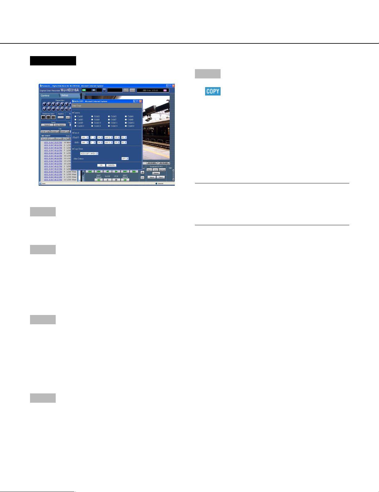
Screenshot 2
The [Data Copy] window will be displayed.
Step 2
Click to select the desired camera channel to be copied.
It is possible to select two or more camera channels.
Step 6
Click the [OK] button.
→ will be displayed in the status display area
when copying starts.
When the warning window is displayed, copying will
be canceled.
However, copying will not be performed in the following
cases (the pop-up window will be displayed):
• When another user has selected the desired copy
drive
• When the auto copy function is enabled
• When copying is being performed manually
Important:
Copying will be performed in the following order:
Viewer Software → Images → Audio
Depending on the set time range for "Period", some
of images and audio may not be copied.
Step 3
Select a start time and an end time for copying by clicking the [i] button.
It is possible to designate up to 99 minutes and 59 seconds of the time range per download. (Copying will stop
automatically when the size of the copied data reaches
4 GB even before the end time of the set time range.)
Step 4
Select a destination where the copied file is to be saved
from the following by clicking the [i] button.
HDD COPY AREA: Built-in hard disk of this unit
COPY1: External recording device connected to the
COPY1 port of this unit
COPY2: External recording device connected to the
COPY2 port of this unit
Step 5
Select whether or not to attach a code for the alteration
detection using the viewer software by clicking the [i]
button.
OFF: Do not attach a code for the alteration detection.
ON: Attach a code for the alteration detection.
50
Page 51
Disk Management
Perform the settings for the built-in hard disk of the unit and the DVD-RAM disk. These are the descriptions of how to
delete recorded images on the hard disk and how to format a DVD-RAM disk.
Refer to a system administrator for further information about the other disks.
Deletion of recorded images saved on the hard disk manually
Delete recorded images saved in the normal area or the event area of the hard disk manually.
By setting a time and date, the images recorded the day before the set time and date will be subject to deletion.
Notes:
• It is impossible to recover the deleted images.
• It is possible to delete recorded images automatically when the set days have passed from the day the image
was recorded (HDD auto deletion). Refer to a system administrator for further information.
• When "STOP" is selected for "Disk End Mode", the available disk space will not be increased even though deletion is performed.
Screenshot 1
Start operation from the top page.
Step 1
Click the [Setup] tab.
Screenshot 2
The setup menu (Quick) will be displayed.
Step 2
Click "Advanced Setup Menu".
51
Page 52
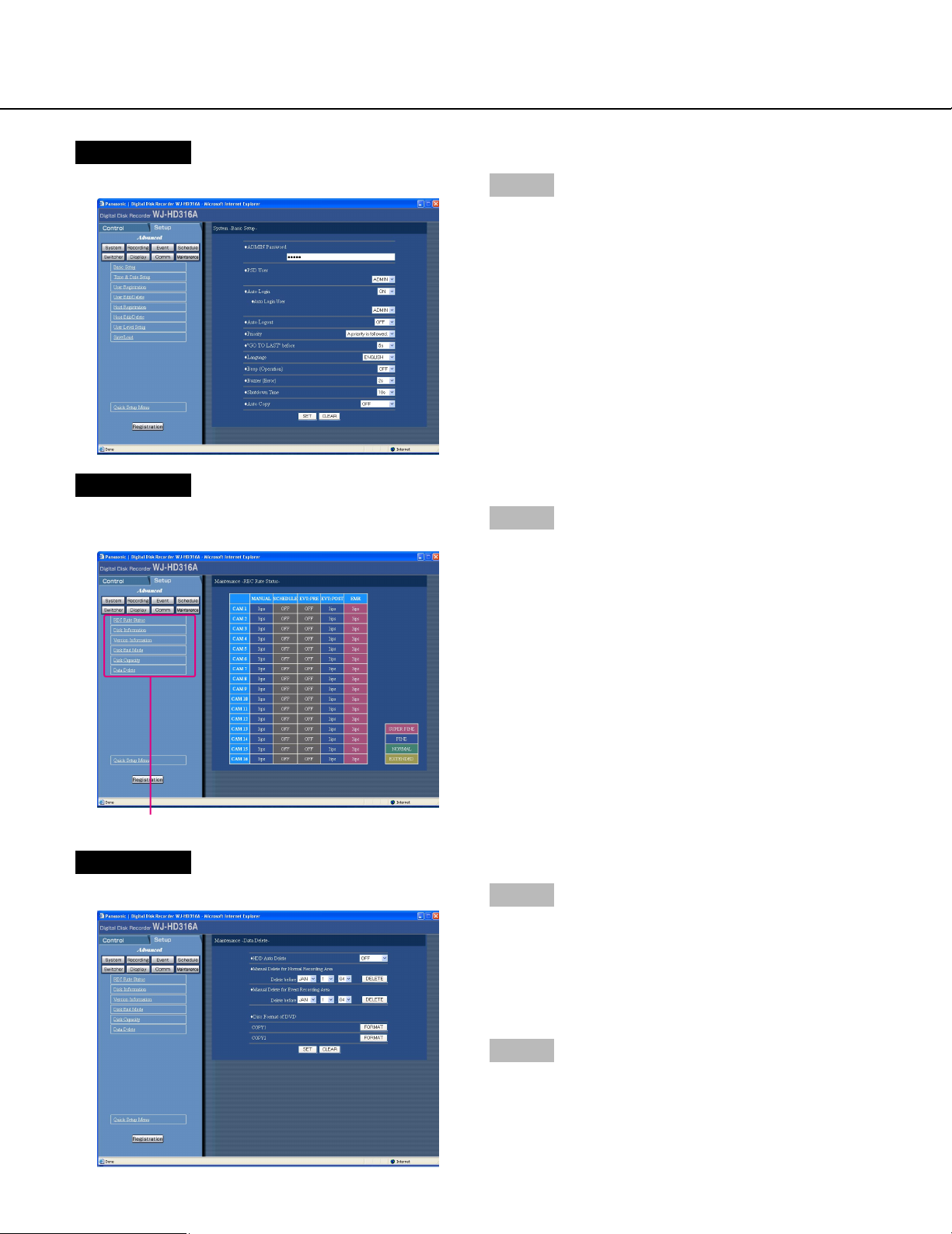
Screenshot 3
The setup menu (Advanced) will be displayed.
Screenshot 4
The [Maintenance] submenu will be displayed in the
[Setup] tab.
Step 3
Click the [Maintenance] button.
Step 4
Click "Data Delete".
[Maintenance] submenu
Screenshot 5
The [Data Delete] menu will be displayed.
52
Step 5
Set the time and date for "Manual Delete for the normal
recording area" or "Manual Delete for the event recording area".
Images recoded before the set time and date will be
deleted.
Step 6
Click the [DELETE] button.
Page 53

Screenshot 6
The confirmation window will be displayed.
Step 7
Click the [OK] button.
→ Start deletion.
53
Page 54
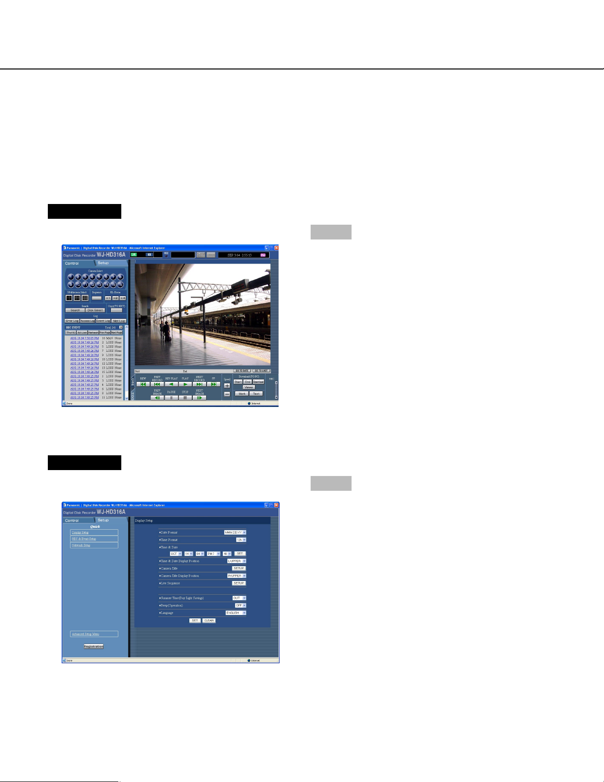
Format (initialize) a DVD-RAM disk
To copy (duplicate) recorded images onto the DVD-RAM disk, formatting (initializing) the DVD-RAM disk is required
in advance.
Format (initialize) the DVD-RAM disk to delete images recorded on the DVD-RAM disk.
Screenshot 1
Start operation from the top page.
Step 1
Click the [Setup] tab.
Screenshot 2
The setup menu (Quick) will be displayed.
Step 2
Click "Advanced Setup Menu".
54
Page 55
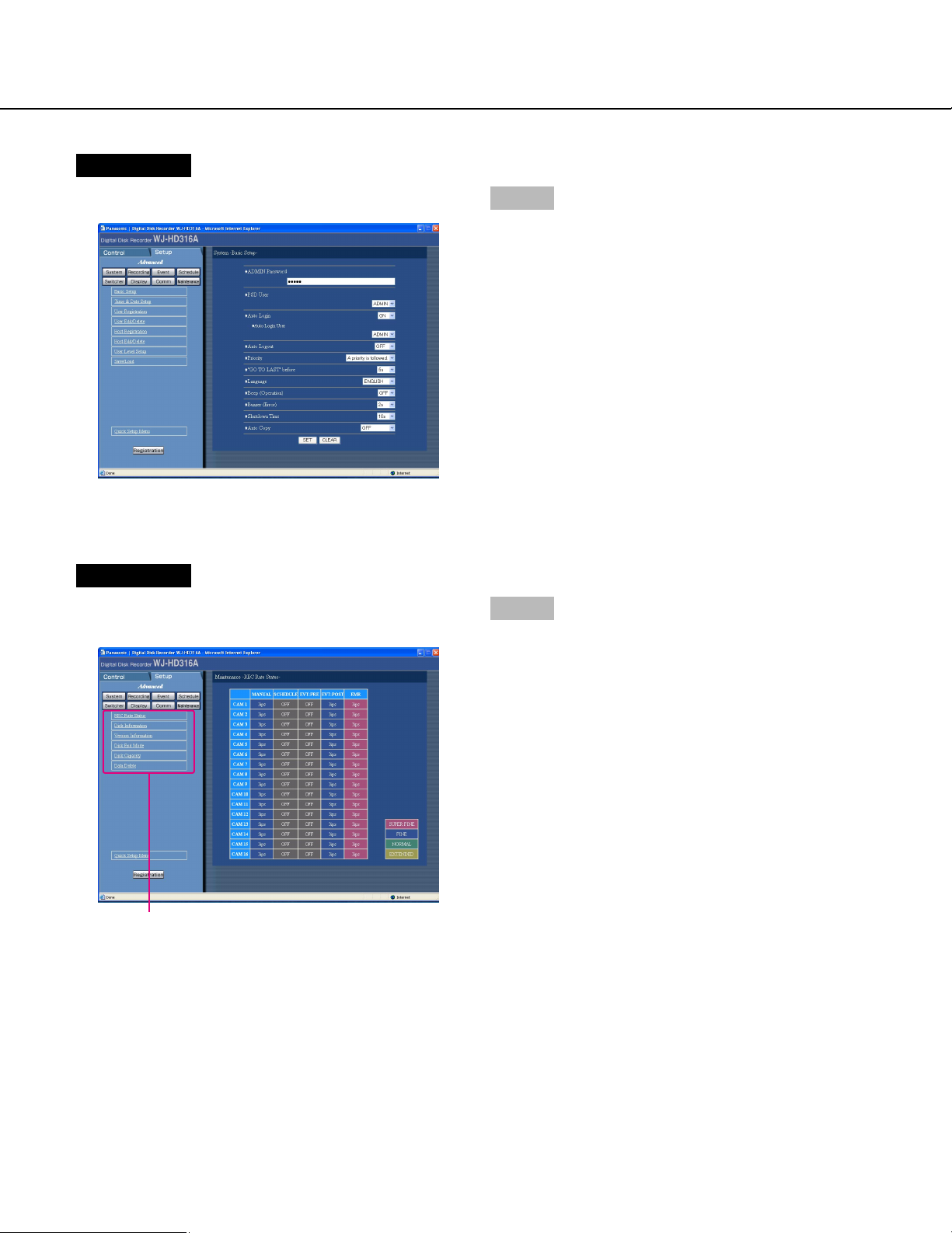
Screenshot 3
The setup menu (Advanced) page will be displayed.
Screenshot 4
The [Maintenance] submenu will be displayed in the
[Setup] tab.
Step 3
Click the [Maintenance] button.
Step 4
Click "Data Delete".
[Maintenance] submenu
55
Page 56
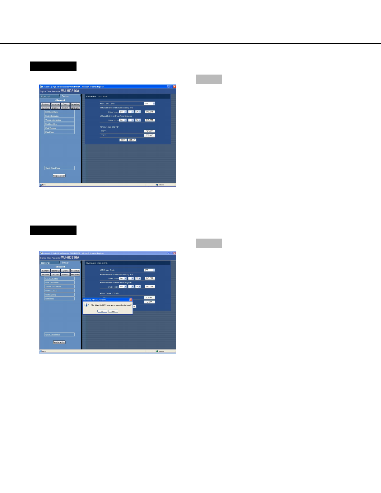
Screenshot 5
The "Data Delete" menu will be displayed.
Screenshot 6
The confirmation window will be displayed.
Step 5
Click the [FORMAT] button of [COPY1] or [COPY2] of
[Disk format of DVD].
(Click the [FORMAT] button for the port to which the
disk to be formatted is connected.)
Step 6
Click the [OK] button.
→ Formatting will begin.
56
Page 57

Screenshot 7
The formatting completion window will be displayed.
Step 7
Click the [OK] button.
57
Page 58
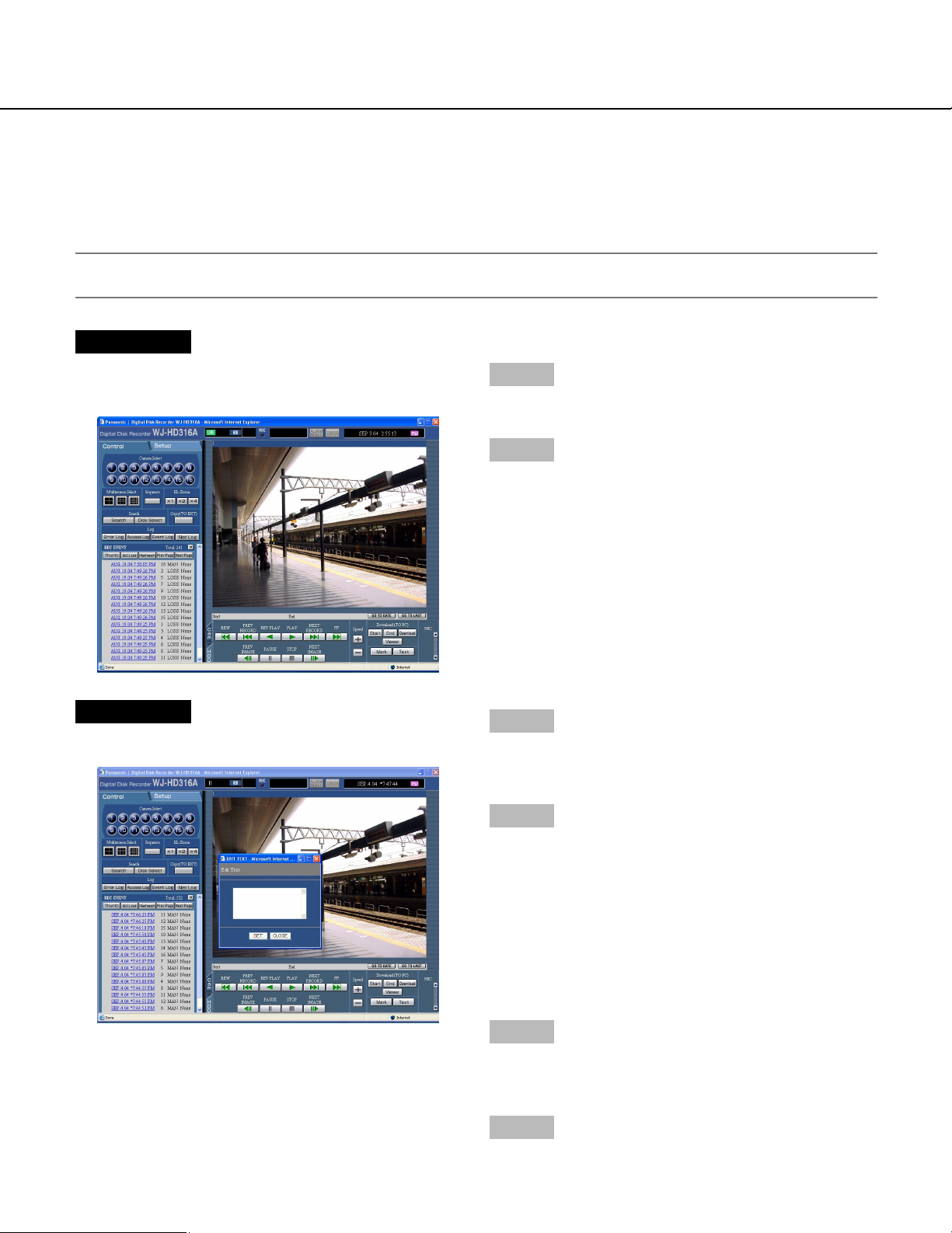
Display/edit the text information
It is possible to attach text information to images when recording.
It is possible to enter up to 200 characters for text information.
These are the descriptions of how to display/edit the attached text information to images.
Note:
Displaying/editing text information is possible during pausing playback on a single screen.
Screenshot 1
Start operation after starting playback of recorded
images in a single screen.
Step 1
Pause playback by clicking the [Pause] button.
Step 2
Click the [TEXT] button in the [HDD] tab.
Screenshot 2
The [EDIT TEXT] window will be displayed.
Step 3
The text information attached to the recorded images
will be displayed.
Step 4
Edit text information
• About the available characters
The following alphanumeric characters can be
entered.
A B C D E F G H I J K L M N O P Q R S T U V W X
Y Z a b c d e f g h i j k l m n o p q r s t u v w x y z 0 1
2 3 4 5 6 7 8 9 ! " # $ % & ' ( ) * + , - . / : ; < = > ? @ [
\ ] ^ _ ` | } ~
Step 5
Click the [SET] button.
→ The text information will be registered.
Step 6
Click the [CLOSE] button.
→ The [EDIT TEXIT] window will close.
58
Page 59
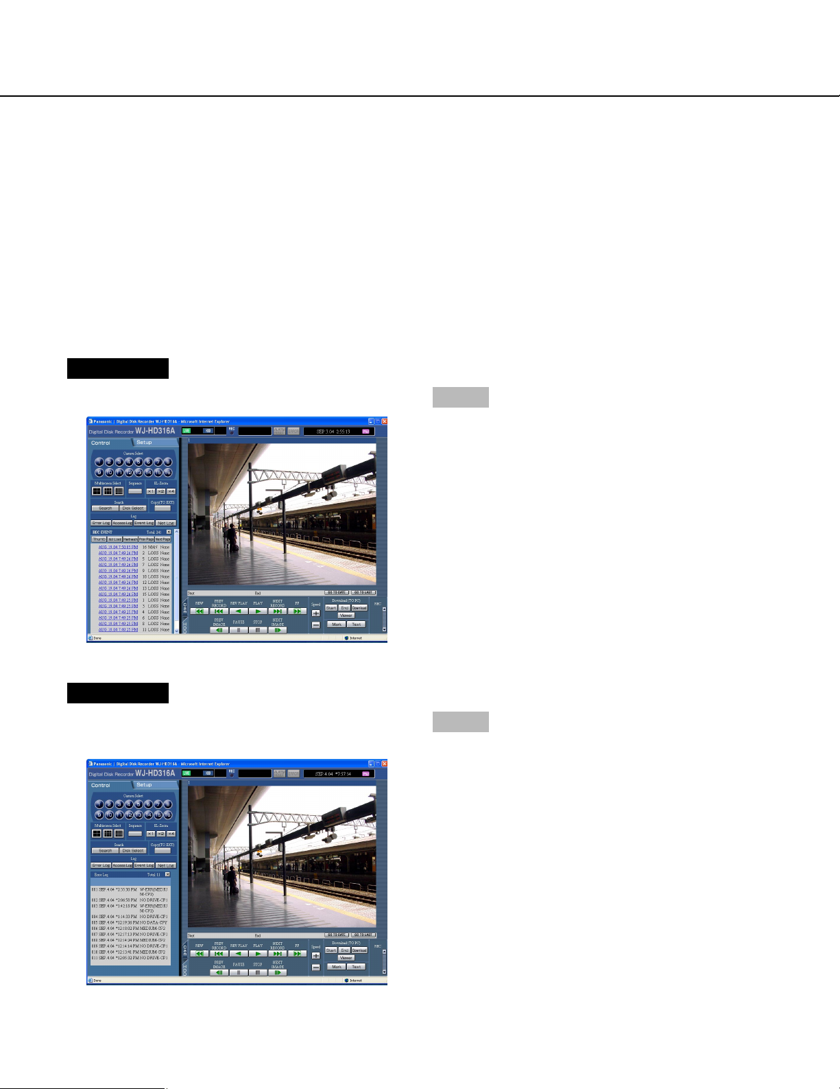
Check logs
The following logs can be checked.
• Error log
• Access log
• Event log (event occurrence time and details)
• Network trouble log
Check the error log.
The error log will be displayed in list form.
Screenshot 1
Start operation from the top page.
Step 1
Click the [Error Log] button in the [Log] box of the
[Control] tab.
Screenshot 2
The error log (the error log window) will be displayed in
list form below the [Control] tab.
Step 2
Click the [×] button to close the error log window.
59
Page 60

About the error log
Indication
AL*-YYMMDDhhmmss
Description Cause
Asterisk (*) indicates the camera channel number
YYDDMMhhmmss indicates the time
when the alteration was detected.
Detects alteration
W-ERR X-Y
R-ERR X-Y
REMOVE X-Y X indicates the unit/unit number that
#-FULL # indicates the partition name/external
THERMAL -X
FAN X-Y X indicates the unit/unit number
X indicates the unit/unit number that
has the hard disk error
Y indicates the disk number in the unit
(unit number)
X indicates the unit/unit number that
has the hard disk error
Y indicates the disk number in the unit
(unit number)
has the hard disk that has been
removed from the subject for recording.
Y indicates the disk number in the
unit/unit number
recording device port number
X indicates the unit/unit number in
which the thermal error occurred
Y indicates the fan number (1-4)
Y will be left out if the malfunctioning
fan is in the extension unit
Failed to write data on the HDD
Failed to read data on the HDD
Auto removal of the link
No available disk space
Thermal error
The fan is malfunctioning
60
#-nn% # indicates the partition name of the
hard disk/external recording device
nn indicates the available disk space
SMART X-Y
PWR LOSS
H.METER X-Y X indicates the unit/unit number that
PROTECT -# # indicates the port number to which
NO DISK -# # indicates the port number to which
X indicates the unit/unit number that
has the hard disk error
Y indicates the unit/unit number
has the hard disk error
Y indicates the unit/unit number
the external recording device is connected
the external recording device is connected
Warning that the disk space is running
out
HDD SMART error
Detects a power outage
Hour-meter warning
Disk has the write protection
Disk is not inserted
Page 61

MEDIUM -#
Indication Description Cause
# indicates the port number to which
the external recording device is connected
Incompatible disk
UNFORMATTED -#
W-ERR (MEDIUM-#)
PWR RECOVER
HDD ERROR
M-FAIL MAIN X
R-FAIL X
NO DATA-#
# indicates the port number to which
the external recording device is connected
# indicates the port number to which
the external recording device is connected
X indicates disk number
X indicates extension unit number
# indicates the port number to which
the external recording device is connected
Unformatted disk
Failed to write data on the disk (CD-R,
DVD-RAM, DVD-R)
Recover from a power outage
HDD error
Mirroring recovery failure
RAID recovery failure
Manual copy settings error
(No image in the designated time
range)
NO DRIVE-#
R-ERR (MEDIUM-#)
# indicates the port number to which
the external recording device is connected
# indicates the port number to which
the external recording device is connected
Copy drive is not connected
Failed to read the medium of the copy
drive
Note:
Up to 100 error logs can be kept. When more than 100 error logs are filed, the older error logs will be overwritten
by the newer error logs. In this case, the oldest log is the first to be overwritten.
61
Page 62
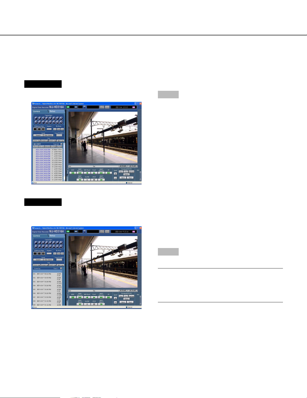
Check the access log
Information on logging on/out for this unit such as the time, user name, and IP address will be displayed.
Screenshot 1
Start operation from the top page.
Step 1
Click the [Access Log] button in the [Log] box of the
[Control] tab.
Screenshot 2
The access log (the access log window) will be displayed in list form below the [Control] tab.
**IN: The user name or the IP address displayed before
IN indicates the user/host logged in.
**OUT: The user name or the IP address displayed
before OUT indicates the user/host logged out.
**: A user name or IP address will be displayed.
Step 2
Click the [×] button to close the access log window.
Notes:
• Up to 100 access logs can be kept. When more than
100 access logs are filed, the older access logs will
be overwritten by the newer access logs. In this
case, the oldest log is the first to be overwritten.
62
Page 63
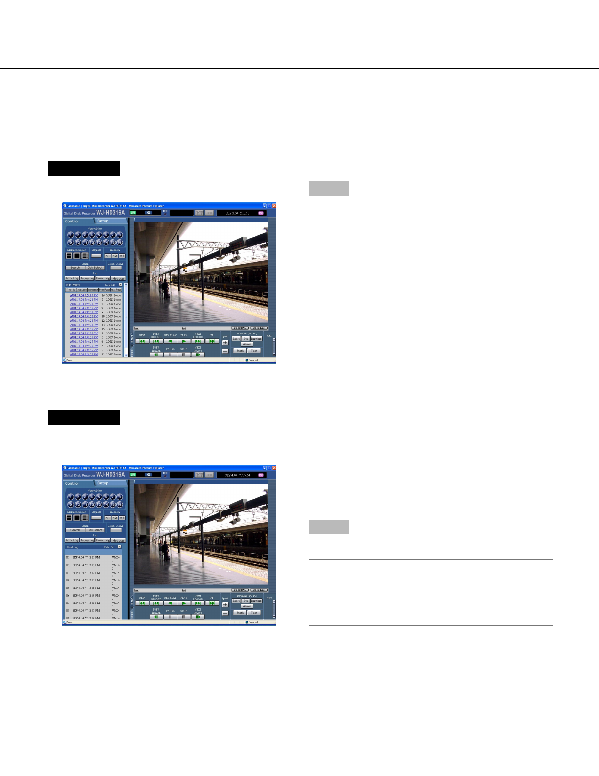
Check the event log
The event log (event occurrence time and details) will be displayed in list form.
Refer to page 46 for further information about each event.
Screenshot 1
Start operation from the top page.
Step 1
Click the [Event Log] button in the [Log] box of the
[Control] tab.
Screenshot 2
The event log (the event log window) will be displayed
in list form below the [Control] tab.
Indications for event log
COM: Command alarm
EMR: Emergency recording
LOSS: Video Loss
TRM: Terminal Alarm
VMD: Motion detection alarm
Step 2
Click the [×] button to close the event log window.
Note:
Up to 750 event logs can be kept. When more than
750 event logs are filed, the older event logs will be
overwritten by the newer event logs. In this case, the
oldest log is the first to be overwritten.
63
Page 64
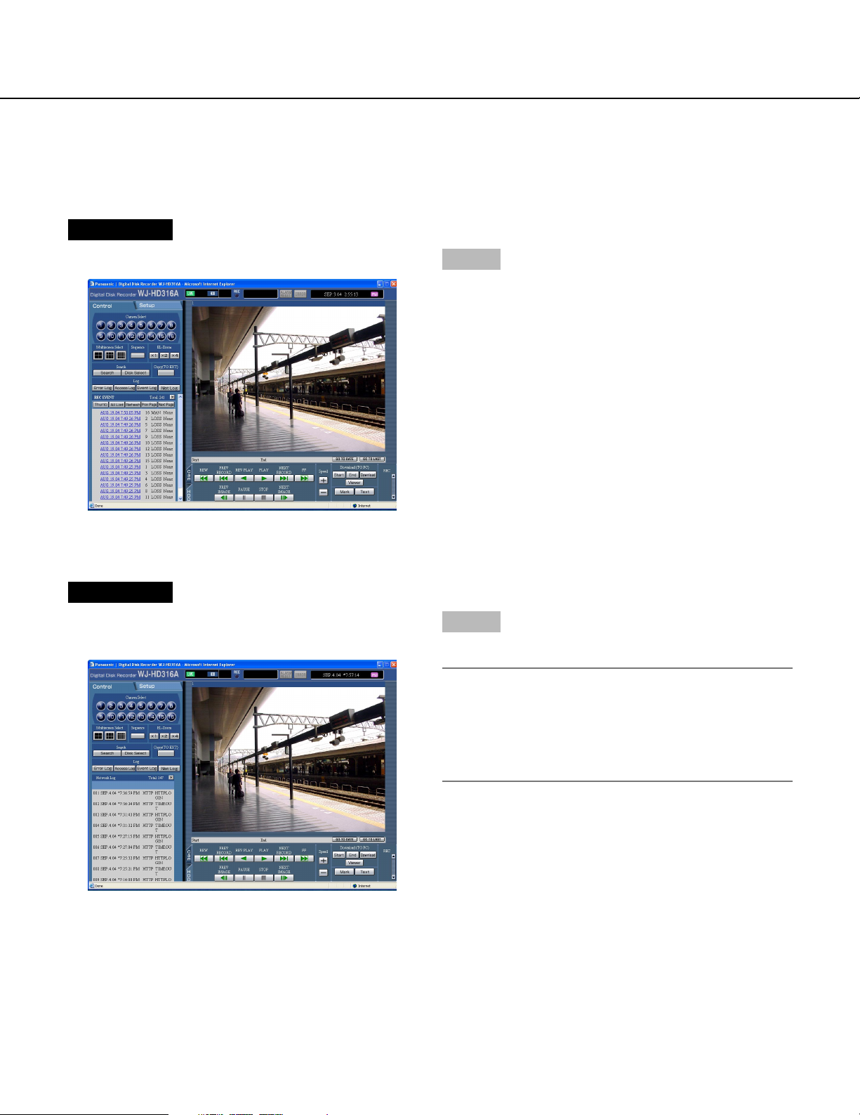
Check the network trouble log
The network log (network event) will be displayed in list form.
Screenshot 1
Start operation from the top page.
Step 1
Click the [Net Log] button in the [Log] box of the
[Control] tab.
Screenshot 2
The network trouble log (the NW log window) will be displayed in list form below the [Control] tab.
Step 2
Click the [×] button to close the NW log window.
Note:
Up to 1000 network trouble logs can be kept. When
more than 1000 network trouble logs are filed, the
older network trouble logs will be overwritten by the
newer network trouble logs. In this case, the oldest
log is the first to be overwritten.
64
Page 65

About the network trouble log
Indication Description
SMTPMAIL_SEND Send mail
SMTPATTEST_ERR Authentication error
SMTPPOP3ADD_ERR Failed to resolve POP3 server address from DNS
SMTPPOP3SVR_ERR Failed to find POP3 server
SMTPSVRADD_ERR Failed to resolve SMTP server address from DNS
SMTPSVR_ERR Failed to find SMTP server
SMTPMAILFROM_ERR MAIL FROM command error
SMTPRCPTTO_ERR RCPT TO command error
SMTPOTHER Other error for SMTP
FTPCLIENT_OK Client transmission succeeded
FTPSVRFWD_OK Server transmission succeeded
FTPSVRADD_ERR Failed to resolve FTP server address from DNS
FTPSVR_ ERR Failed to find FTP server
FTPUPLOAD_ ERR FTP uploading error
FTPPASSIVE_ ERR Passive mode error
FTPLOGOUT_ ERR Failed to log out
FTPOTHER Other error for FTP
DDNSIPADDUIPDATE_OK IP address updated
DDNSSVRRES_ERR No response from the server
DDNSUSERPASS_ ERR Password error for user name
DNSIPADDUPDATE_OK IP address updated
DNSOTHER Other error for DNS
NTPGETTIME_OK Synchronization with the NTP server succeeded
NTPSVRADD_ERR Failed to resolve NTP server address from DNS
NTPSETTIME_ERR Failed to synchronize with the NTP server
NTPSVRRES_ERR No response from the server
NTPOTHER Other error for NTP
SNMPSEND_OK Transmission succeeded
SNMPUSERPASS_ ERR Password error for user name
SNMPOBJ_ERR Failed to acquire SNMP object
SNMPOTHER Other error for SNMP
DHCPIPADD_OK Having IP address succeeded
DHCPIPADD_LOST Lost IP address
DHCPIPADDUPDATE_ ERR Failed to update IP address xx%
DHCPIPADDENT_ ERR Failed to register IP address
DHCPOTHER Other error for DHCP
HTTPLOGIN Login
TIMEOUT Timeout
HTTPUSERPASS_ERR Error of user name/password
HTTPUSERPASS_ERR Failed to download
HTTPUSERPASS_ERR Invalid request
HTTPUSERPASS_ERR No authority
HTTPOTHER Other error for HTTP
65
Page 66
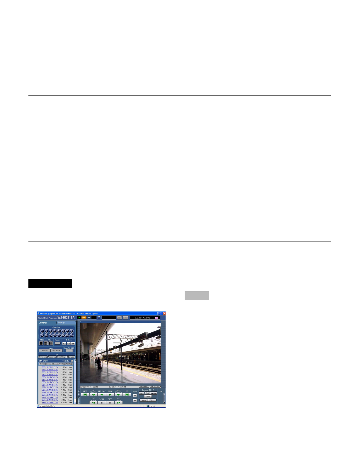
Download recorded images
Designate the start point and the end point of played images and download images to a PC.
Recorded images will be downloaded as image data files (filename.h3r). Refer to page 69 for the descriptions of how
to play the downloaded images.
Important:
• When using the FAT32 file system, the size of the file to be downloaded for one attempt should be less than 4
GB.
Use the following as references for the file size:
The size of the file to be downloaded will be approximately 4 GB when the settings are as follows:
Resolution: FRAME
Color Mode: COLOR FINE
Image Quality: SFB
Recording Rate: 30 ips
Time range (recorded duration) of the recorded images to be downloaded: approximately 30 minutes
• The size of the file to be downloaded will be approximately 30 MB when the settings are as follows:
Resolution: FIELD
Color Mode: COLOR STD
Image Quality: FQB
Recording Rate: 3 ips
Time range (recorded duration) of the recorded images to be downloaded: approximately 10 minutes
• When downloading, the available disk space must be 2 or more times the size of the file to be downloaded. It is a
feature of Internet Explorer.
• Do not interrupt downloading. Otherwise, it may be impossible to properly play the downloaded file on a PC.
Screenshot 1
Start operation after starting playback of recorded
images in a single screen.
66
Step 1
Click the [HDD] tab.
Page 67
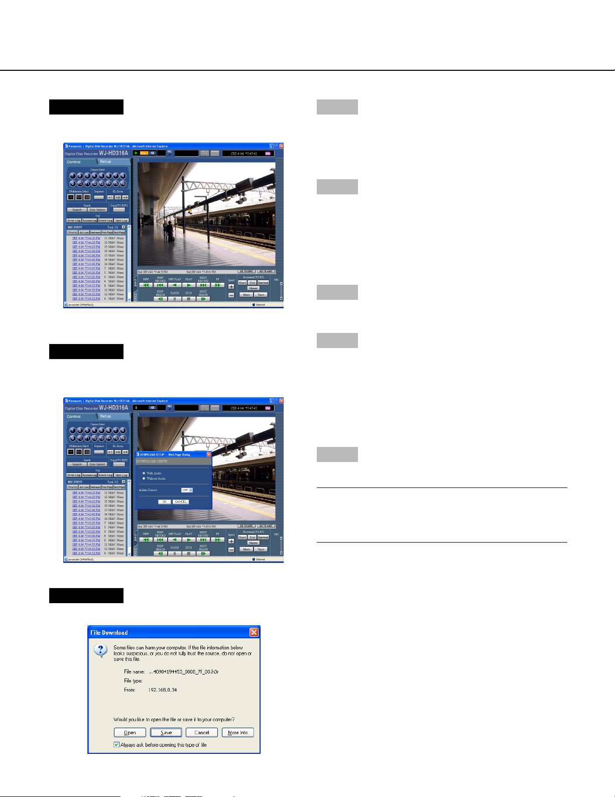
Screenshot 2
The [HDD] page will be displayed.
Screenshot 3
The "DOWNLOAD SETUP" pop-up window will be displayed.
Step 2
Click the [Start] button in the [Download (TO PC)] box at
the desired point of the image to be downloaded.
→ The time and date of the start point will be displayed
in the playback position display area.
Step 3
Click the [End] button in the [Download (TO PC)] box at
the desired point of the image to be downloaded.
→ The time and date of the end point will be displayed
in the playback position display area.
It is possible to designate up to 30 minutes of the
time range per download.
Step 4
Click the [Download] button.
Step 5
Click the OK button after checking "With Audio" or
"Without Audio" to download recorded images whether
with or without audio and selecting "ON" or OFF" for
"Alter Detect" to determine whether or not to attach an
alteration detection code to recorded images to be
downloaded.
Screenshot 4
The download window will be displayed.
Step 6
Click the [Save] button.
Note:
When "With Audio" is checked in step 5, the download window will be displayed again after downloading of the image data files has been completed.
67
Page 68
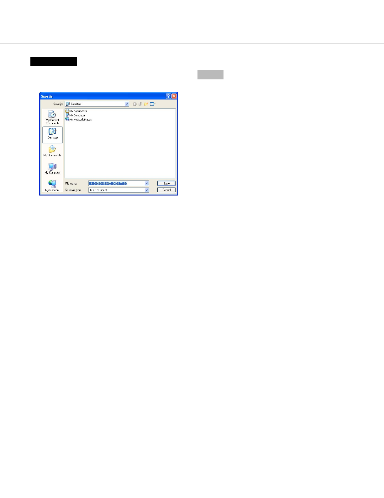
Screenshot 5
The window designating a directory for the downloaded
file will be displayed.
Step 7
Create a new folder in the desired directory and click
the [Save] button.
→ The image data file (extension: h3r) will be down-
loaded.
68
Page 69
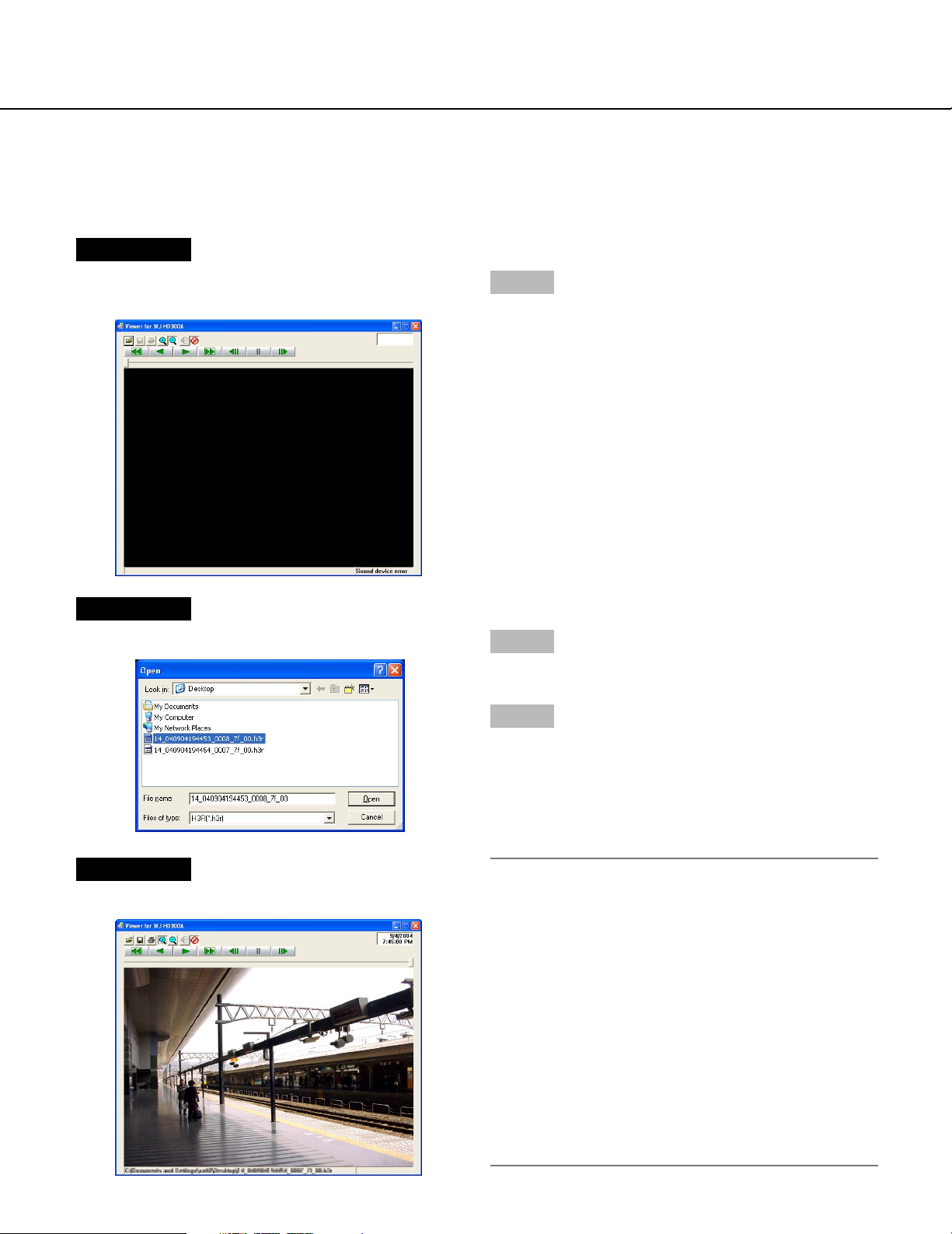
Play downloaded images
Recorded images will be downloaded as image data files (filename.h3r). Use the viewer software on the provided
CD-ROM to browse downloaded image data.
Screenshot 1
Double click the viewer software on the provided CDROM to start up and display the following window.
Step 1
Click the [Open file] button.
Screenshot 2
The [Open file] window will be displayed.
Screenshot 3
An image will be displayed.
Step 2
Select the downloaded image data file (filename.h3r).
Step 3
Click the [Open] button.
Notes:
• The "*" mark indicates that summer time will be not
displayed with the time and date display on the viewer.
• Sometimes, audio may not be heard for several seconds at the end of playback. This is not a malfunction.
• When the time range for downloading an image data
file with audio is too short, audio may not be heard
when playing the downloaded images.
• Audio and images may not always be synchronized
during playback.
• When playing a file with the extension "go4"
(attached file to an alarm mail), the playback rate will
be fixed at 2 ips.
69
Page 70
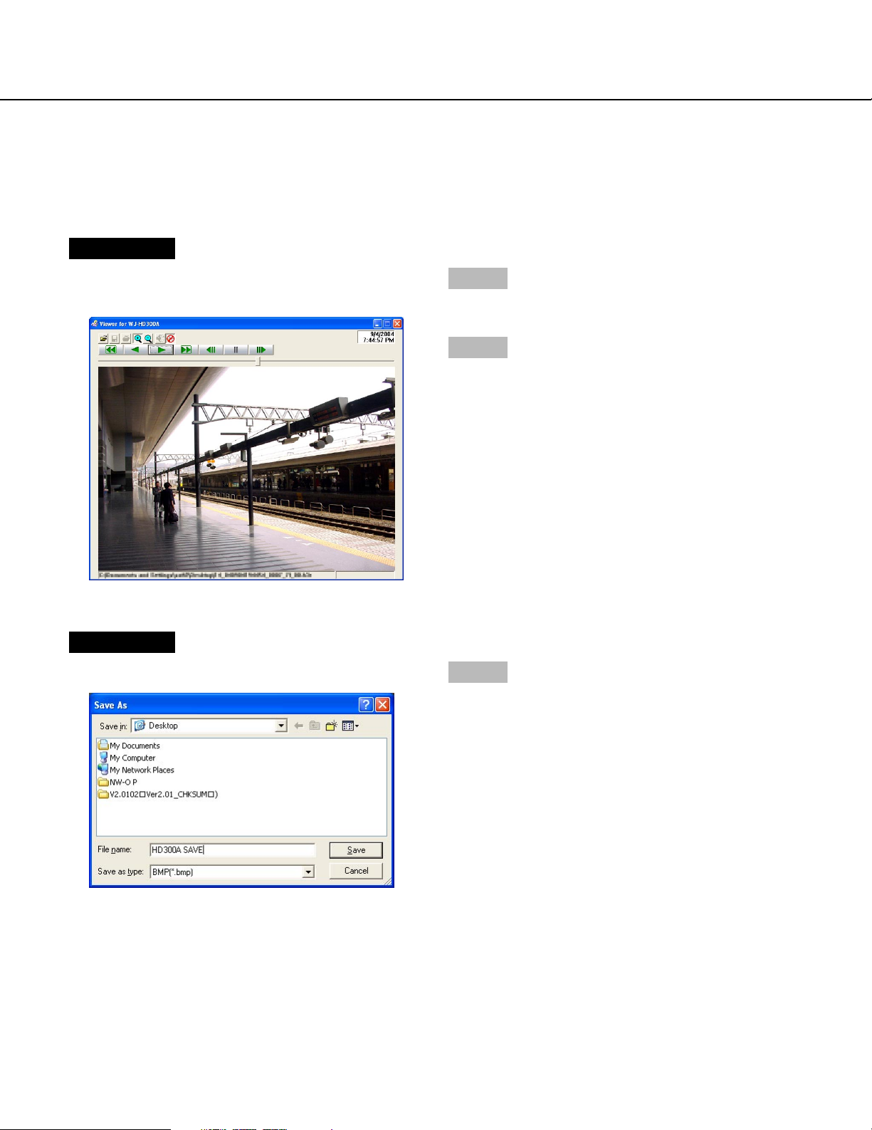
Save downloaded images
When playback of the downloaded images using the viewer software is paused, it is possible to save the paused
image as a bitmap file (extension: bmp) or a jpeg file (extension: jpg).
Screenshot 1
Start operation when playing the downloaded images
using the viewer software.
Step 1
Click the [PAUSE] button.
Step 2
Click the [SAVE] button.
Screenshot 2
The "Save as…" window will be displayed.
Step 3
Click the [SAVE] button after designating the file name,
file format (BMP or JPG/JPEG) and the directory where
the file is to be saved.
→ The image data will be downloaded and saved.
70
Page 71
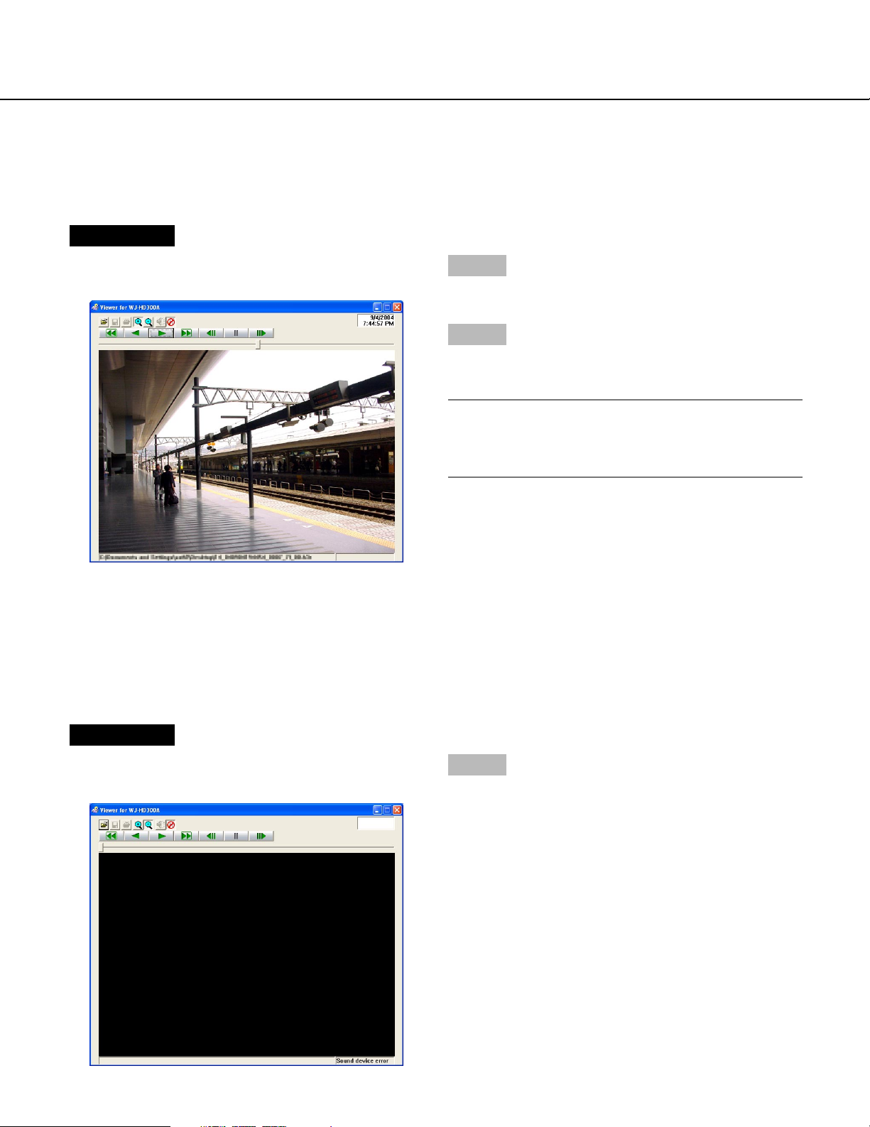
Print the displayed image
When playback of the downloaded images using the viewer software is paused, it is possible to print the paused
image. Refer to an administrator for further information about the settings of printers.
Screenshot 1
Start operation when playing the downloaded images
using the viewer software.
Step 1
Click the [PAUSE] button.
Step 2
Click the [PRINT] button.
→ The paused image will be printed.
Note:
The time and date being displayed on the viewer
when paused will also be printed above the printed
image.
Perform the alteration detection
It is possible to detect the alteration of the data if a code for the alteration detection has been attached to the
copied/downloaded data. Refer to page 50 for descriptions of how to attach a code for the alteration detection.
Screenshot 1
Start up the viewer software.
The screen shown below will be displayed.
Step 1
Click the [OPEN] button.
71
Page 72
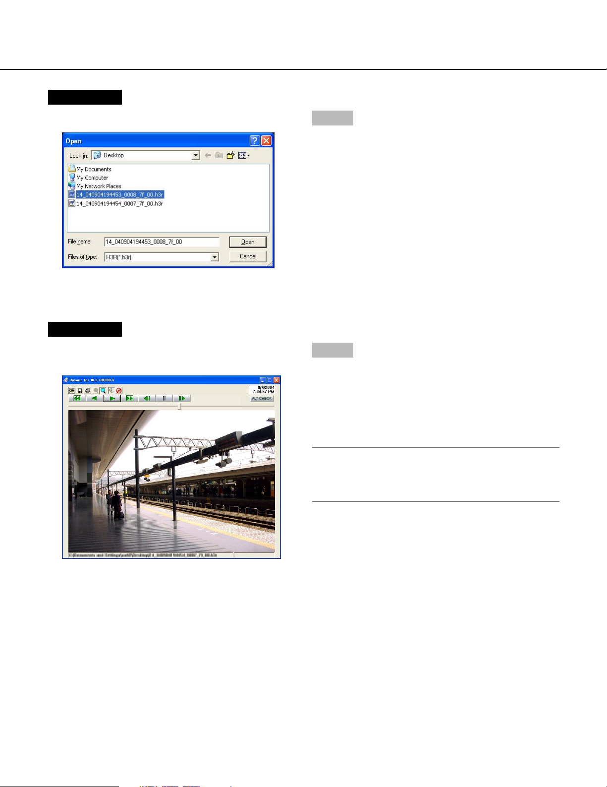
Screenshot 2
The [Open file] window will be displayed.
Screenshot 3
The paused image (the first frame of the data file) will
be displayed.
Step 2
Click the [OPEN] button after selecting the desired
copied image data file (extension: h3r).
Step 4
Click the [ALT CHK] button.
→ The alteration detection will start.
The following pop-up window will be displayed
while/after performing the alteration detection.
OK (Not Altered) No alteration was detected.
NG (Altered) Alteration was detected.
Note:
The [ALT CHECK] button will be displyed only when
opening an image data file with a code for the alteration detection.
72
Page 73

Notification by e-mail
Alarm mail notification
The following mail will be sent to notify of an alarm occurrence to a registered address when an alarm occurs.
In HD316A (192.168.0.250), alarm was occurred.
Alarm date: xxx-xx-xxxx xx:xx:xx (Example: JAN-1-2004 12:00:00 AM)
Cause of alarm: Displays an event type and a camera channel or an alarm number (Example: VMD 5CH)
File name of alarm image: The file name of the image attached to an e-mail.
URL: http://192.168.0.250/
It is possible to edit the contents of the alarm mail that notifies of the event occurrence with the time and date of the
event occurrence.
To edit the alarm mail, do the following.
Step 1
Edit the contents using text editing software and save in the text format.
Depending on the item (time and date at an event occurrence, cause of alarm, host address, etc.) to be displayed,
the characters to be entered will be different. Refer to the following list of characters to be replaced when editing the
contents of the mail. Save the edited mail contents with the file name "almmail.tmpl".
Step 2
Start up the FTP software and enter the IP address of the unit to connect to that unit.
Enter the user name and password as follows.
User Name: ADMIN
Password: Password entered for ADMIN on the SETUP MENU. (The default password is 12345.)
Refer to a system administrator for further information about the settings of user name and password.
Step 3
Transfer the edited file (almmail.tmpl) in the text format.
The directory to be sent is as follows.
/user/HD300/HTML_FILES
73
Page 74

List of characters to be replaced
Item to be displayed Display style of Example
entered characters
Time and date when the alarm occurred %#05100000 Month, day, year (4-digit), hour, minute, second
(JAN - 1 - 2004 12:00:00)
Year when the alarm occurred (4-digit) %#05000000 4-digit display (2002 - 2099)
Month when the alarm occurred (number) %#05000100 1 or 2-digit display (1 - 12)
Month when the alarm occurred (3 letters) %#05000200 Displays first 3 letters (Jan, Feb … Dec)
Day when the alarm occurred %#05000300 1 or 2-digit display (1 - 31)
Time when the alarm occurred %#05000400 24-hour display (15:00:00)
Mail address of the sender %#05000500
Host name of HD316A %#05000600 HD316
IP Address of HD316A %#05000700 192.168.0.250
Cause of the alarm %#05000800 Terminal: Terminal, VMD: VMD, Command:
Command, Video loss: VideoLoss, Emergency
recording: Emergency
Alarm number %#05000900 1 or 2-digit (1 - 16) + CH
File name of the alarm image %#05001000 xx_ALMyyyymmddhhmmss.GO4
Remains blank when no alarm image exists.
xx: Camera channel number
yymmdd: Date (year, month, day) when the
yy
alarm occurred
hhmmss: Time (hour, minute, second) when the
alarm occurred
URL %#05001100 "Host Name"."Domain Name":"HTTP port num-
ber" (ended with a slash(/))
• When "Host Name" and "Domain Name" are
set (Only when "OFF" is selected for "DDNS")
• When the host name and the domain name
are obtained correctly using DDNS (Only
when "ON" is selected for "DDNS")
"IP Address":"HTTP port number" (ended with a
slash(/))
• When "Host Name" and "Domain Name" are
not set (Only when "OFF" is selected for
"DDNS")
• When the host name and the domain name
failed to be obtained correctly using DDNS
(Only when "ON" is selected for "DDNS")
Note: The part following the IP address (:"HTTP
port number) will be omitted when "80" is set
for "HTTP Port Number".
74
Page 75

Warning mail notification
The following mail will be sent to notify of a trouble occurrence to a registered address when the trouble occurs.
WJ-HD316A (192.168.0.250) STATUS REPORT.
DATE: xxx-xx-xxxx xx:xx:xx JAN-1-2004 12:00:00 AM
STATUS: The description of the trouble will be displayed. (Example: THERMAL ERROR)
Display Description
DATE Time and date when the trouble occurred will be displayed.
STATUS The description of the trouble will be displayed.
Thermal trouble: THERMAL ERROR
Alteration detection: ALTERED
HDD write error detection: DISK ERROR XX
XX indicates disk number (sequential serial number)
1: Disk no.1 of the unit
2: Disk no.2 of the unit
3: Disk no.1 of the connected extension unit
(Continues if more disks are connected/installed)
HDD smart warning: DISK WARNING XX
XX indicates disk number (sequential serial number)
1: Disk no.1 of the unit
2: Disk no.2 of the unit
3: Disk no.1 of the connected extension unit
(Continues if more disks are connected/installed)
HDD Capacity warning*1: <except FULL>
HDD-NORMAL CAPACITY REMAINS ** %
HDD-EVENT CAPACITY REMAINS ** %
** indicates set value (%) - 1
<FULL>
HDD-NORMAL IS FULL
HDD-EVENT IS FULL
HDD hour meter warning: HDD HOUR METER WARNING
Power outage detection: POWER LOSS
Remove auto links: LOGICALLY REMOVED HDD XX
XX indicates disk number (sequential serial number)
1: Disk no.1 of the unit
2: Disk no.2 of the unit
3: Disk no.1 of the connected extension unit
(Continues if more disks are connected/installed)
Fan trouble: FAN ERROR
Copy media trouble: MEDIUM ERROR HDD error:
HDD-ERROR Mirroring recovery failure: MIRROR RECOVERY FAILURE
X (X indicates disk number)
RAID recovery failure: RAID5 RECOVERY FAILURE X-Y
(X indicates unit number, Y indicates disk number)
Other troubles: UNDEFINED ERROR
* 1: HDD capacity warning
A warning mail with the contents of <except FULL> will be sent when the available disk space becomes less than
the set value for "Capacity warning" in the "Maintenance" menu. After a warning mail is sent, a warning mail with the
<except FULL> content will be sent each time 1% of the available disk space is reduced, and a warning mail with the
<FULL> content will be sent when there is no available disk space.
Note:
It is impossible to edit a warning mail.
75
Page 76

About error mail
An error mail with the following contents will be sent to a registered address when the available hard disk space of
the copy area or an external recording disk (DVD-RAM disk, DVD-R disk, CD-R disk) is less than the set level, or
when the disk has no available disk space.
WJ-HD316A (192.168.0.250) STATUS REPORT.
DATE: xxx-xx-xxxx xx:xx:xx JAN-1-2004 12:00:00 AM
STATUS: The description of the capacity warning will be displayed.
(Example: HDD-COPY CAPACITY REMAINS 10 %)
Display Description
DATE Time and date when an error occurred will be displayed.
STATUS The description of the capacity warning will be displayed.
<except FULL>
HDD-COPY CAPACITY REMAINS ** %
COPY1 CAPACITY REMAINS **%
COPY2 CAPACITY REMAINS **%
** indicates set value (%) - 1
<FULL>
HDD-COPY IS FULL
COPY1 IS FULL
COPY2 IS FULL
HDD capacity warning
A warning mail with the <except FULL> content will be sent when the available disk space becomes less than the
set value for "Capacity warning" in the "Maintenance" menu. After a warning mail is sent, a warning mail with the
<except FULL> content will be sent each time 1% of the available disk space is reduced, and a warning mail with the
<FULL> content will be sent when there is no available disk space.
Note:
It is impossible to edit a warning mail.
76
Page 77

Troubleshooting
Before asking for repairs, check the symptoms with the following table.
Contact your dealer if a problem cannot be solved even after checking and trying the solution or a problem is not
described below, and when having a problem with installations.
Symptom
Cannot access from the
browser.
Cause/solution
• Is the Ethernet cable firmly connected to the
10/100BASE-T port? Confirm the cable is firmly
connected.
• Is the connection indicator of the 10/100BASE-T
port lit? When it is not lit, connection to a LAN is
not established or a network is not working correctly. Confirm that the connection indicator of the
10/100BASE-T port is lit. Refer to a system administrator if it is not lit.
• Is the valid IP address set?
Refer to a system administrator for further information.
• Are you accessing the wrong IP address?
Check the connection as follows:
>ping "IP address of this unit"
If there is reply from this unit, the connection is
normal.
If not, check the settings of the IP address and the
subnet mask.
Reference
pages
–
–
Refer to the
Network Setup
Instructions on the
provided CD-ROM.
–
• Is the same IP address provided to other devices?
Refer to a system administrator for further information.
• Are there contradictions between the address and
the network subnet to be accessed?
Or is "Use Proxy Server" for the settings of the
browser checked?
When accessing this unit in the same subnet,
entering the address of this unit in the "Don’t Use
Proxy For These Addresses" box is recommended.
Refer to the
Network Setup
Instructions on the
provided CD-ROM.
Refer to the
Network Setup
Instructions on the
provided CD-ROM.
77
Page 78

Symptom
The image is not being
refreshed.
Cause/solution
• Depending on the traffic of the network, there
might be difficulties in displaying images. Press
the [F5] button on the keyboard to request images.
Reference
pages
–
Cannot close the authentication window displayed
when displaying the basic
operation window.
Audio sounds fragmentary
when using the viewer software.
Cannot play the downloaded
image file.
• Are the correct user name and password entered?
Confirm the correct user name and password.
• Audio may sound fragmentary when playing
images recorded with a high recording rate.
• When any setting of the SETUP MENU has been
changed during the download, the download will
be canceled automatically. In this case, the downloaded file is not a complete file and it is impossible to play it.
Refer to the
Network Setup
Instructions on the
provided CD-ROM.
–
–
78
Page 79

Panasonic Digital Communications & Security Company
Unit of Matsushita Electric Corporation of America
Security Systems Group
www.panasonic.com/cctv
Executive Office: One Panasonic Way 3E-7, Secaucus, New Jersey 07094
Zone Office
Eastern: One Panasonic Way, Secaucus, NJ 07094 (201) 348-7303
Central: 1707 N.Randal Road, Elgin, IL 60123 (847) 468-5205
Western: 6550 Katella Ave., Cypress, CA 90630 (714) 373-7840
PANASONIC CANADA INC.
5770 Ambler Drive, Mississauga,
Ontario, L4W 2T3 Canada (905)624-5010
PANASONIC SALES COMPANY
DIVISION OF MATSUSHITA ELECTRIC OF PUERTO RICO INC.
San Gabriel Industrial Park 65th Infantry Ave. KM. 9.5 Carolina,
P.R. 00985 (809)750-4300
© 2004 Matsushita Electric Industrial Co., Ltd. All Rights Reserved. N0904-1114 V8QB6249BN Printed in Japan
 Loading...