

Page 1

Before attempting to connect or operate this product,
please read these instructions carefully and save this manual for future use.
–
+
TIMER
ERROR
ALARM
RESET
HDD 1
HDD 2
PULL
ALARM
ALARM
SUSPEND
OPERATE
Digital Disk Recorder
WJ-HD
316
A
MONITOR1
MONITOR2
SHIFT
DISK SELECT
EL-ZOOM
COPY
TEXT
MARK
PAN/
TILT
ZOOM/
FOCUS
IRIS
LISTED
BUSY
A-B
REPEAT
PAN/TILT
SLOW
SETUP
/ESC
SEARCH
REV
FWD
SET
GOTO
LAST
PRESET
/AUTO
LOGOUT
OSD
SEQ
1
4
7
8
9
11
12
13
14
15
16
10/0
5
2
6
3
- REC STOP
REC-
STOP
PAUSE
PLAY
Digital Disk Recorders
Network Setup Instructions
Model Nos. WJ-HD309A
WJ-HD316A
Page 2

2
Page 3

3
CONTENTS
Preface .............................................................................................................................. 4
Features ........................................................................................................................ 4
Downloading/transmitting images ................................................................................. 4
Event notification function ............................................................................................. 4
Host authentication ....................................................................................................... 4
About these operating instructions ................................................................................ 4
System requirements for a PC ...................................................................................... 5
Trademarks and registered trademarks ........................................................................ 5
Abbreviations ................................................................................................................ 5
About notations ............................................................................................................. 5
Preparations ...................................................................................................................... 6
Connections .................................................................................................................. 6
Performing the network settings .................................................................................... 7
About the network security of this unit ........................................................................ 10
Display the operation window .......................................................................................... 11
How to display the operation window .......................................................................... 11
About the operation window ........................................................................................ 13
Setup ............................................................................................................................... 19
Setup menu (Quick) chart ........................................................................................... 19
Basic operation with the setup menu (Quick) .............................................................. 19
[Display Setup] ............................................................................................................ 21
[REC & Event Setup] ................................................................................................... 24
[Network Setup] ........................................................................................................... 28
Setup menu (Advanced) chart .................................................................................... 30
Basic operation with the setup menu (Advanced) ....................................................... 33
Perform the settings for the system [System] ............................................................. 35
Functions for recording [Recording] ............................................................................ 50
Functions for events [Event] ........................................................................................ 55
Settings for the recording/event schedule [Schedule] ................................................. 62
Settings for switcher function [Switcher] ..................................................................... 73
Settings for display [Display] ....................................................................................... 79
Settings for communication with other devices [Comm] ............................................. 84
Settings for maintenance [Maintenance] ................................................................... 104
Notification by e-mail ..................................................................................................... 110
Alarm mail notification ............................................................................................... 110
Warning mail notification ............................................................................................... 112
About error mail ............................................................................................................. 113
Troubleshooting ............................................................................................................. 114
Page 4

4
Preface
Features
It is possible to perform the settings or operate the unit using a PC when this unit is connected to a network.
The following functions are available when using a PC via a network as well as the functions operable on the buttons
on the front panel of the unit.
Refer to the Network Operating Instructions (PDF) on the provided CD-ROM for further information about the available functions.
Downloading/transmitting images
It is possible to download (save) the currently displayed image in the web browser window onto the hard disk of a
PC. By establishing an FTP server, it is possible to transmit images to the designated FTP server. When an event
occurs, it is possible to transmit images from the camera installed in the place where the alarm occurred.
Event notification function
When an event occurs, it is possible to send e-mails to designated addresses to notify of the event occurrence. It is
also possible to send an e-mail with an image recorded when the event occurred.
Host authentication
It is possible to restrict devices from operating this unit if their IP addresses are not registered.
About these operating instructions
There are 3 sets of operating instructions for the WJ-HD316A/WJ-HD309A as follows.
• Operating Instructions (book)
• Network Operating Instructions (PDF)
• Network Setup Instructions (PDF, these Operating Instructions)
These "Network Setup Instructions" contain descriptions of how to perform the required settings to operate this unit
using a PC via a network and descriptions for installations such as how to connect the unit to other devices.
The settings of the unit will be different depending on the settings of the LAN or the Internet service provider to which
the unit is to be connected.
Refer to an administrator of each network for further information about the respective network.
Refer to the provided "Operating Instructions (book)" for descriptions of how to operate this unit using the buttons on
the front panel of the unit, installation and system configurations.
Refer to the "Network Operating Instructions (PDF)" for descriptions of how to operate this unit using a PC.
Adobe®Reader is required to read these operating instructions (PDF) on the provided CD-ROM. When the Adobe
®
Reader is not installed on the PC, download the latest Adobe®Reader from the Adobe web site and install it.
"WJ-HD300A" or "HD300A" shown in the illustrations used in these operating instructions indicate this unit or the
WJ-HD300A series.
Page 5

5
System requirements for a PC
It is recommended to operate this unit using a PC that meets the following system requirements. If using a PC that
does not meet the following system requirements, it may cause problems such as slow imaging or the browser
becomes inoperable.
OS Microsoft®Windows®2000 Professional SP4
Microsoft®Windows®XP Professional or Home Edition SP2
Computer IBM PC/AT Compatible
CPU Pentium®4 1.4GHz or faster
Memory 512 MB or more
Monitor 1024 x 768 pixels or more, 16-bit HIGH color or better
Network Interface 10/100Mbps Network interface card must be installed
Web Browser Microsoft®Internet Explorer 5.5SP2, 6.0 SP1
Other web browsers are not compatible with this unit.
Important:
To operate this unit, the plug-in software is required to be installed. The plug-in software will be downloaded and
installed automatically when accessing the unit using a browser. If the plug-in software has not been downloaded/installed correctly, install it from the provided CD-ROM. Refer to "readme.txt" on the provided CD-ROM
for the descriptions of how to install it.
Trademarks and registered trademarks
• Adobe, Adobe logos, and Acrobat are registered trademarks of Adobe Systems Incorporated in the U.S. and/ or
other countries.
• Microsoft, Windows and Windows XP are registered trademarks of Microsoft Corporation in the U.S. and/or other
countries.
• Other names of companies and products contained in these operating instructions may be trademarks or registered trademarks of their respective owners.
Abbreviations
The following abbreviations are used in these operating instructions.
Microsoft
®
Windows®2000 Professional Service Pack 4 is described as Windows 2000.
Microsoft®Windows®XP is described as Windows XP.
About notations
Important: Restrictions or cautions to operate respective functions.
Note: Tips to operate respective functions.
Page 6
6
Preparations
Connections
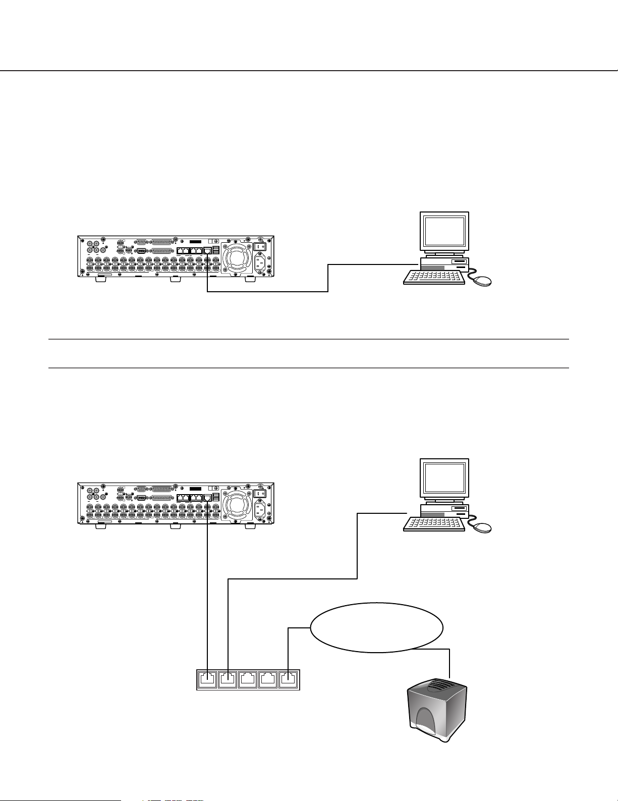
When connecting this unit to a PC, the required hardware and cables are different depending on the system configuration. Prepare before starting connection.
Connecting this unit and a PC directly.
Connecting this unit to a PC directly using a LAN cable.
Important:
Use a cross cable when connecting this unit and a PC directly without using a hub or a router.
Add this unit to an existing network
Connecting this unit to a PC via a hub or a router. Connecting this unit to a hub using a LAN cable.
1
1
IN
OUT
3
4 2
AUDIO IN AUDIO OUT
16
16
1515141413
SERIAL ALARM
CASCADE
OUT
2
MONITOR OUT CASCADE IN
MONITOR (VGA) ALARM/CONTROL
13
12121111101099887766554433221
VIDEO
IP Address: 192.168.0.250
Subnet mask: 255.255.255.0
18
MODE
COPY 1
1
2
DATA
EXT STORAGE10/100BASE-TRS485(CAMERA)
1
LAN cable
(Not provided: 10BASE-T/100BASE-Tx
Category 5, Cross)
SIGNAL GND
POWER
AC IN
IBM PC/AT Compatible
IP Address: 192.168.0.x (except 0, 250 and 255)
Subnet mask: 255.255.255.0
This unit
SERIAL ALARM
MONITOR (VGA) ALARM/CONTROL
VIDEO
This unit
DATA
18
MODE
1
2
COPY 1
EXT STORAGE10/100BASE-TRS485(CAMERA)
1
SIGNAL GND
POWER
AC IN
IN
OUT
1
3
4 2
AUDIO IN AUDIO OUT
16
16
1
CASCADE
OUT
2
MONITOR OUT CASCADE IN
13
1515141413
12121111101099887766554433221
IP Address: 192.168.0.250
Subnet Mask: 255.255.255.0
Gateway Address: 192.168.0.1
LAN cable
(Not provided: 10BASE-T/100BASE-Tx
Category 5, Straight)
Hub/Router
IP Address: 192.168.0.1
Subnet Mask: 255.255.255.0
IBM PC/AT Compatible
IP Address: 192.168.0.x (except 0, 1, 250 and 255)
Subnet Mask: 255.255.255.0
Gateway Address: 192.168.0.1
LAN (Local Area Network)
FTP Server
(For transmitting images)
Page 7
7
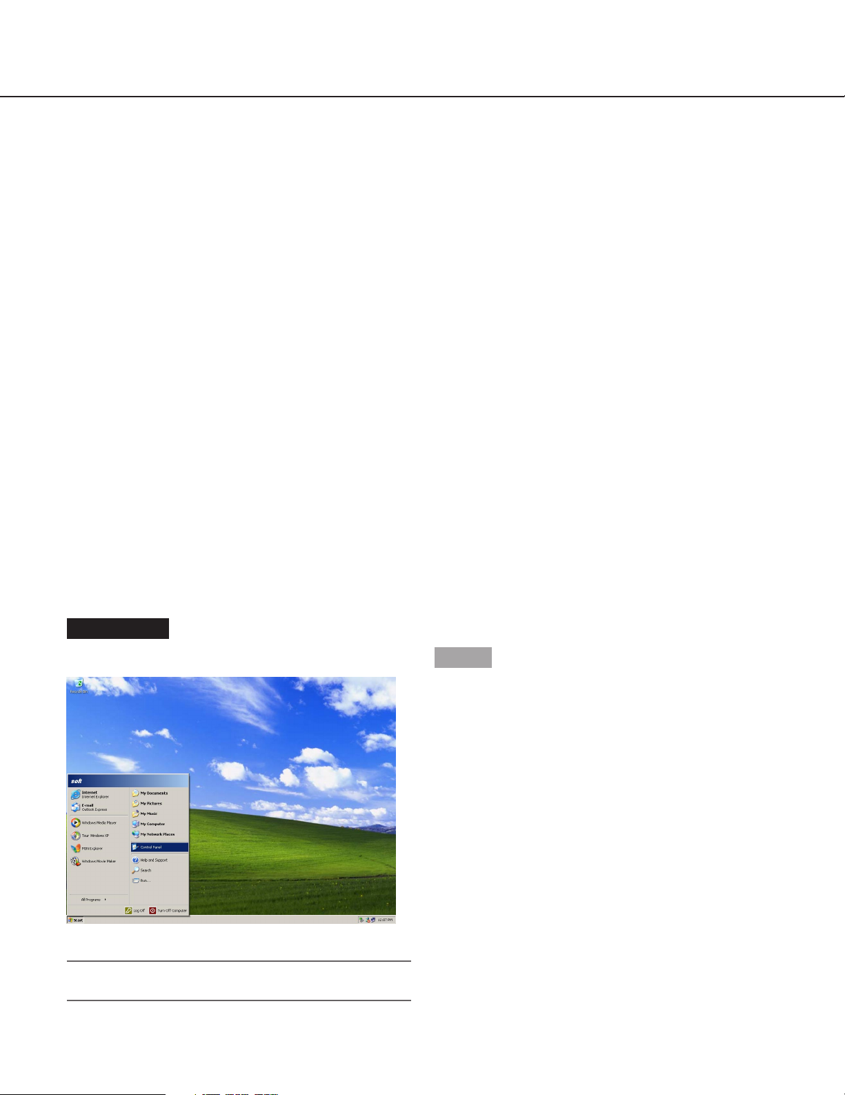
Screenshot 1
Start just after the PC is started up.
Important:
Log in to the PC as an administrator.
Step 1
On the taskbar, click "Start", and then click the "Control
Panel".
Performing the network settings
With the following network environment, it is not necessary to perform the network settings. It is possible to perform
the settings or operate this unit using a web browser after completing the connection.
IP Address: 192.168.0.2 - 192.168.0.249, 192.168.0.251 - 192.168.0.254
Subnet Mask: 255.255.255.0
Gateway Address: 192.168.0.1
When the network settings are different from the settings above, perform the network settings of this unit and the
PC.
Performing the network settings of this unit
Use the buttons on the front panel of this unit to conform the network settings to the network environment of the PC.
Refer to the Operating Instructions (book) for further information about the network settings ([SETUP] - [Comm]
Settings for communication with other devices – [NW Setup 2] Network connection settings).
Performing the network settings of a PC
Change the TCP/IP setting of the PC to conform to the settings of this unit.
It is required to set the IP address of the PC to "192.168.0.XX (a number from 2 to 254 except 250)" to access this
unit.
In these operating instructions, the settings are performed on Windows XP as examples. Refer to the operating
instructions of the respective OS for further information.
Page 8
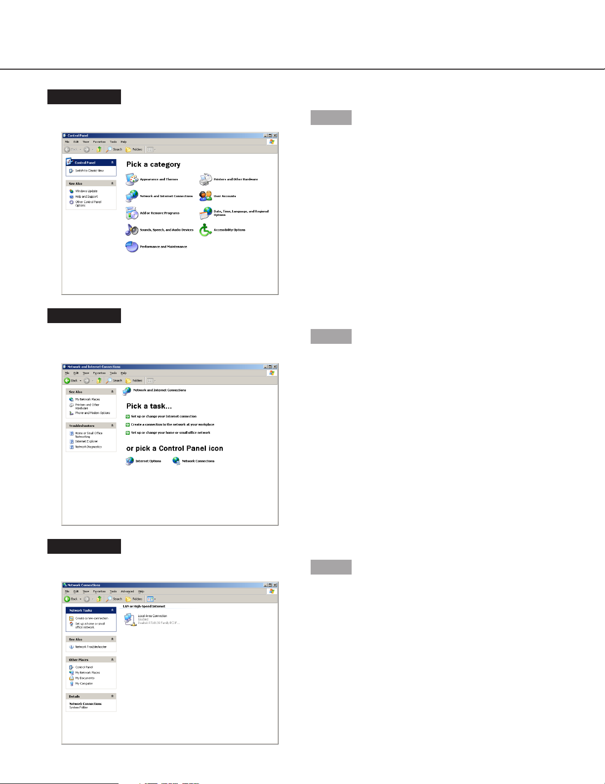
Screenshot 4
The "Network Connections" window will be displayed.
Step 4
Double click "Local Area Connection".
8
Screenshot 2
The control panel will be displayed.
Step 2
Click the "Network and Internet Connections" icon.
Screenshot 3
The "Network and Internet Connections" window will be
displayed.
Step 3
Click "Network Connections".
Page 9
9
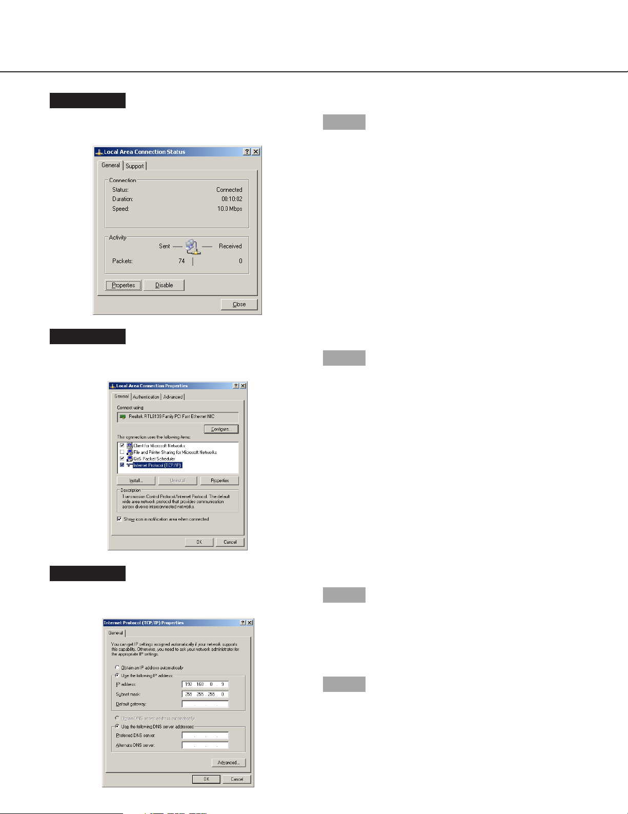
Screenshot 6
The "Local Area Connection Properties" window will be
displayed.
Step 6
Click "Internet Protocol (TCP/IP)", and then click
"Properties".
Screenshot 5
The "Local Area Connection Status" window will be displayed.
Step 5
Click "Properties".
Screenshot 7
The "Properties" window of "Internet Protocol (TCP/IP)"
will be displayed.
Step 7
Click "Use the following IP address" and enter the IP
address and the subnet mask as follows;
• IP Address: 192.168.0.9
• Subnet Mask: 255.255.255.0
Step 8
Click the "OK" button and close the window.
Page 10

10
About the network security of this unit
Equipped security functions
q Access restrictions by the host authentication and the user authentication
It is possible to restrict users from accessing this unit by setting the host authentication and/or the user
authentication to on. (page 93)
w Access restrictions by changing the HTTP port
It is possible to prevent illegal access such as port scanning, etc. by changing the HTTP port number. (page 93)
For enhanced security
Divide the subnet using a router to enhance the network security by double authentications of IP addresses using
this unit and a router. When required to connect this unit with a network without enhanced security, connect the unit
after the network security is enhanced, such as by installing a VPN (Virtual Private Network) device, etc.
Important:
The settings of the unit will be different depending on the settings of the LAN or the Internet service provider to
which the unit is to be connected.
Refer to an administrator of each network for further information about the respective network.
[Connection example]
Installing a firewall to use the packet filtering and the protocol filtering functions can better enhance the network
security.
[Connection example]
Global IP Address
Router Router
IP Address: 192.168.1.1
Subnet Mask: 255.255.255.0
WAN*
IP Address: 192.168.0.1
Subnet Mask: 255.255.255.0
* Stands for Wide Area Network
IP Address: 192.168.1.100
Subnet Mask: 255.255.255.0
Default Gateway: 192.168.1.1
IBM PC/AT Compatible
1
3
CASCADE
OUT
4 2
AUDIO IN AUDIO OUT
MONITOR OUTCASCADE IN
16
13
IN
OUT
16
1515141413
1
SERIAL ALARM
2
MONITOR (VGA) ALARM/CONTROL
DATA
12121111101099887766554433221
VIDEO
This unit
SIGNAL GND
MODE
COPY 1
1182
POWER
EXT STORAGE10/100BASE-TRS485(CAMERA)
1
AC IN
IP Address: 192.168.0.250
Subnet Mask: 255.255.255.0
Default Gateway: 192.168.0.1
Global IP Address
Firewall
IP Address: 192.168.1.1
Subnet Mask: 255.255.255.0
IP Address: 192.168.1.100
Subnet Mask: 255.255.255.0
Default Gateway: 192.168.1.1
Router Router
WAN*
* Stands for Wide Area Network
IBM PC/AT Compatible
IP Address: 192.168.0.1
Subnet Mask: 255.255.255.0
1
3
CASCADE
OUT
4 2
AUDIO IN AUDIO OUT
MONITOR OUTCASCADE IN
13
16
IN
OUT
16
1515141413
Switching hub
1
2
12121111101099887766554433221
SERIAL ALARM
MONITOR (VGA) ALARM/CONTROL
VIDEO
MODE
DATA
This unit
SIGNAL GND
COPY 1
1182
POWER
EXT STORAGE10/100BASE-TRS485(CAMERA)
1
AC IN
IP Address: 192.168.0.250
Subnet Mask: 255.255.255.0
Default Gateway: 192.168.0.1
Page 11

Screenshot 1
Start just after the PC is started up.
Step 1
Start up the web browser.
11
Screenshot 2
The web browser will start up and the set web site will
be displayed.
Step 2
Enter the IP address set to this unit in the address box,
and press the enter key.
Important:
• Refer to a system administrator for the set IP
address of this unit.
• It is impossible to access this unit from a PC without
a registered IP address when "ON" is selected for
"Host Authentication" on the "System" menu.
Refer to a system administrator for further information.
• Do not attach "0" before the numbers when entering
the IP address.
Example
Correct: 192.168.0.50
Wrong: 192.168.0.050
Display the operation window
How to display the operation window
Start up the PC and operate this unit using the installed web browser.
The operation window will be displayed using the following procedure.
Page 12

12
Screenshot 3
The user authentication window will be displayed. This
window will not be displayed when "OFF" is selected for
"User Authentication" on the "NW Setup 1" of "Comm"
menu.
Step 3
Enter the user name and password registered on this
unit.
Important:
• Refer to a system administrator for the set user
name and password.
Refer to page 41 for the descriptions of how to register users.
• The default user name and password are as follows.
User Name: ADMIN
Password: 12345
• To enhance the security, change the password for
an administrator before running the unit. Refer to
page 43 for descriptions of how to change the password.
Screenshot 4
The top page will be displayed.
Step 4
Click the buttons or the tabs for operations.
Page 13

13
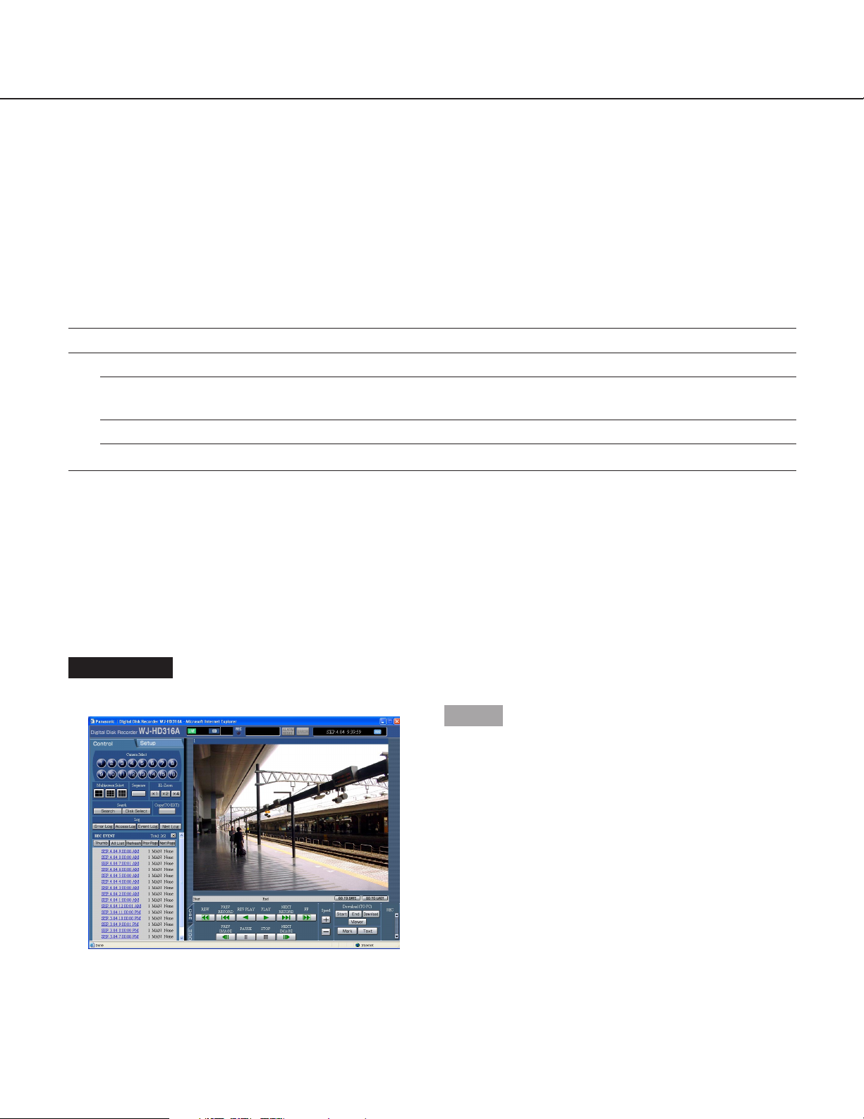
About the operation window
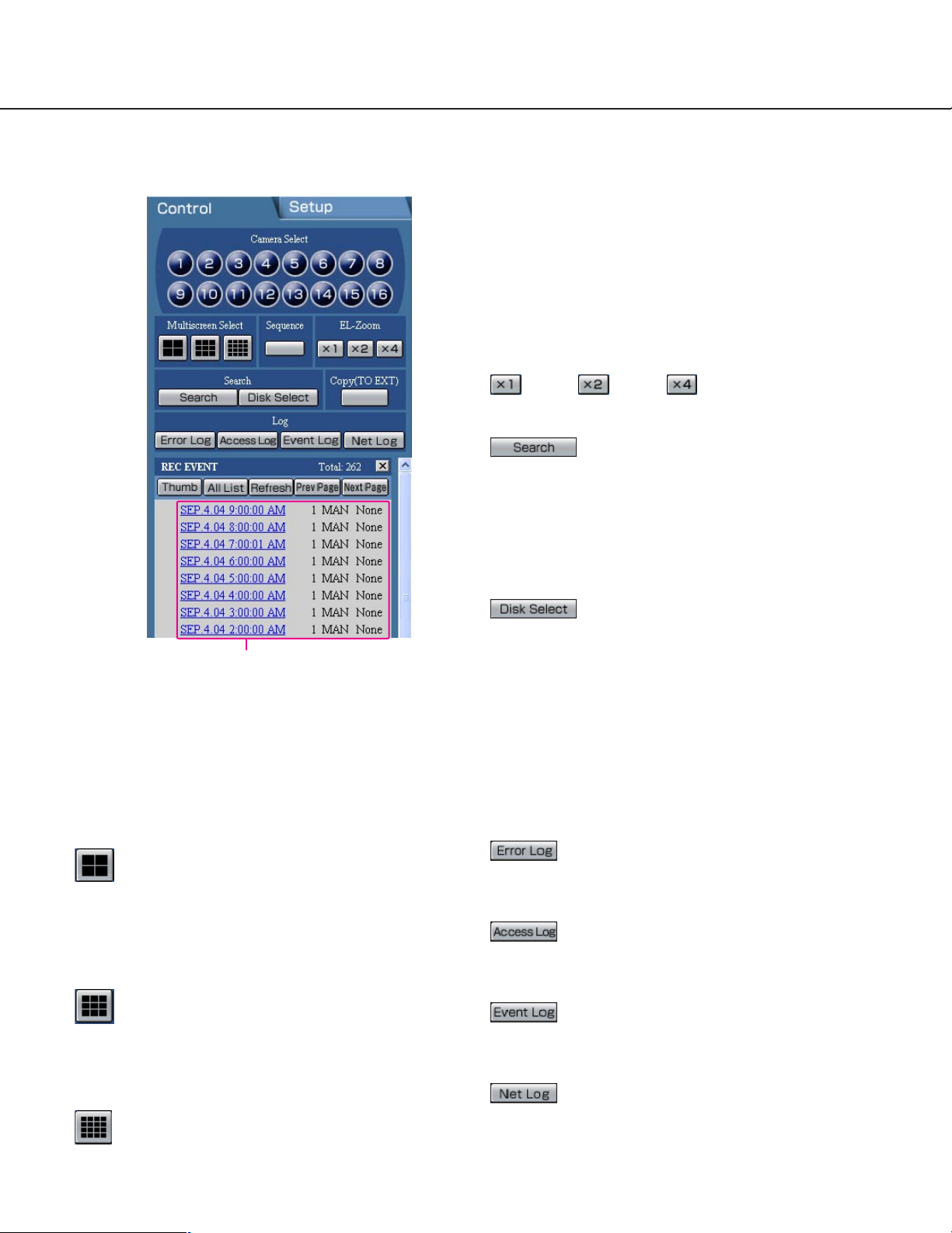
Top page
[Control] tab (page 14)
The switcher functions such as switching camera channels or displaying them sequentially are operable on this
page. Search results or log information will also be displayed on this page.
[Setup] tab (page 15)
Operations for setup of this unit can be performed on
this page.
Using the setup menu (Quick) and the setup
menu (Advanced)
First, check the setting items of the setup menu
(Quick) and perform the settings. When more
detailed settings are required, perform the settings
on the setup menu (Advanced).
Refer to page 30 for descriptions about the setup
menu (Advanced).
Status display area (page 16)
Current status such as playback status or recording status will be displayed.
Current time/recorded time displayed area
When monitoring live images, the current time will be
displayed. When playing recorded images, the recorded
time and date will be displayed.
Image display area
Recorded images and live images will be displayed. The
setup menu will be displayed while setting up.
Playback point operation area (page 17)
It is possible to mark playback points or skip to the latest recorded image.
[HDD] tab (page 17)
Operation for recorded images such as playback or
downloading (saving) recorded images can be performed on this page.
[Cam] tab (page 18)
Controlling cameras by zooming, focusing and auto
panning can be performed on this page.
[Control] tab
[Setup] tab Status display area Current time/recorded time displayed area
Image display area
Playback point
operation area
[HDD] tab
[Cam] tab
Page 14
14
[Camera Select] box
Images from the selected camera channel will be displayed with a spot display on the image display area by
clicking one of these buttons.
[Multiscreen Select] box
Up to 16 camera images can be displayed simultaneously on a multi-screen.
4-split screen button: 4 camera images will be
displayed on a 4-split screen in the following
order each time this button is clicked;
for the WJ-HD316A: 1 - 4 CH → 5 - 8 CH
→ 9 - 12 CH → 13 - 16 CH → 1 - 4 CH ...
for the WJ-HD309A: 1 - 4 CH → 5 - 8 CH → 9 CH
→ 1 - 4 CH ...
9-split screen button: 9 camera images will be
displayed on a 9-split screen in the following
order each time this button is clicked;
For the WJ-HD316A: 1 - 9 CH → 10 - 16 CH
→ 1 - 9 CH...
for the WJ-HD309A: 1 - 9 CH
16-split screen (only for the WJ-HD316A):
Images from 1 - 16 channels will be displayed on
a 16-split screen.
[Sequence] box
Camera images to be displayed will be switched by
clicking this button. Camera images will be displayed
sequentially according to the settings performed in
advance.
[EL-Zoom] box
Camera images will be displayed in the proportion of the
clicked zoom ratio button.
: 1x : 2x : 4x
[Search] box
[Search] button: The "Search Select"
pop-up window will be displayed.
Use this button to search the recorded images and
play them. (Refer to the Network Operating
Instructions (PDF).)
Search results will be displayed in list form in the log
display area. (Refer to the Network Operating
Instructions (PDF).)
[Disk Select] button: The "Disk Select"
pop-up window will be displayed. Use this button to
select a disk to be played/searched. (Refer to the
Network Operating Instructions (PDF).)
[Copy (TO EXT)] box
The copy window will be displayed by clicking this button. Use this when manually copying recorded images
onto the copy area of the hard disk or external recording
devices (DVD-RAM disk, DVD-R disk, CD-R disk).
[Log] box
[Error Log] button: The error logs of this
unit will be displayed.
Logs will be displayed in list form in the log display
area.
[Access Log] button: The time when logged
in/out for this unit, the user name, and the IP
address will be displayed. Logs will be displayed in
list form in the log display area.
[Event Log] button: The event logs (event
occurrence times and their details) will be displayed.
Logs will be displayed in list form in the log display
area.
[Net Log] button: The network error logs will
be displayed. Logs will be displayed in list form in
the log display area.
[Control] tab
Log display area
Page 15
15
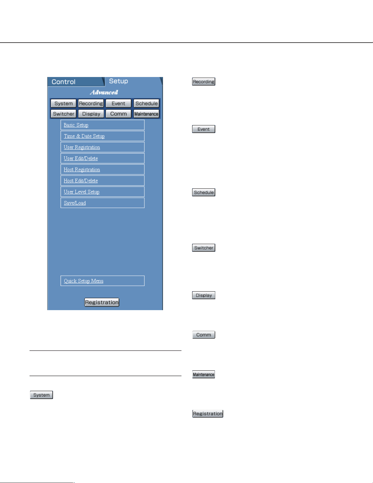
[Setup] tab (Advanced Setup Menu)
Important:
When the settings are applied, all users who have
logged in to this unit will be forcibly logged out.
[System] button
The menu for the required system settings to activate
this unit will be displayed. Refer to page 35 for further
information about this menu.
[Recording] button
The menu for the recording settings will be displayed.
Perform the basic recording settings and emergency
recording with this menu. Refer to page 50 for further
information about this menu.
[Event] button
The menu for the settings of actions at an event occurrence for each event type (terminal alarm, motion detection alarm, video loss alarm and command alarm) will be
displayed.
Refer to page 55 for further information about this
menu.
[Schedule] button
The menu for the settings of the recording schedule
(performs recording/event action by designating the
time and a day of the week) will be displayed.
Refer to page 62 for further information about this
menu.
[Switcher] button
The menu for the image switching settings such as the
sequential operation on monitors 1 and 2, or for displaying the login window will be displayed. Refer to page 73
for further information about this menu.
[Display] button
The menu for the display settings of monitors 1 and 2
will be displayed. Refer to page 79 for further information about this menu.
[Comm] button
The menu for the required settings to communicate with
external devices will be displayed. Refer to page 84 for
further information about this menu.
[Maintenance] button
The menu for the settings of the hard disk will be displayed. Refer to page 104 for further information about
this menu.
[Registration] button
Applies the settings to this unit. Click this button to complete the setting after editing on the Setup menu.
Page 16

16
Status display area
q The status of a live/playback image will be
displayed.
[LIVE]:
Indicates that a live image is being displayed.
[SEQ]:
Indicates that a live image is being displayed in
the sequential display mode.
[Playback]:
Indicates that a playback image is being displayed.
[Reverse playback]:
Indicates that a reverse playback image is being
displayed.
[Fast playback]:
Indicates that a fast playback image is being displayed.
[Fast reverse playback]:
Indicates that a fast reverse playback image is
being displayed.
[Pause]:
Indicates that a paused image is being displayed.
[HDD]:
Indicates that playback of a recorded image
stored in the normal recording area or the event
recording area of the built-in hard disk of this unit
is currently being selected.
[HDD COPY]:
Indicates that the HDD copy area is currently
being selected.
[COPY1]:
Indicates that the external recording device connected to the COPY1 port is currently being
selected.
[COPY2]:
Indicates that the external recording device connected to the COPY2 port is currently being
selected.
[FILTERING]:
Indicates that the recording event list/thumbnail
is filtered.
Refer to the Network Operating Instructions
(PDF) for further information about filtering of the
recording event list.
– [Step1] – [Step7]:
Indicates the playback speed.
Step
1: Normal playback speed
Step2: Approx. 4x playback speed
Step3: Approx. 8x playback speed
Step4: Approx. 16x playback speed
Step5:Approx. 32x playback speed
Step6: Approx. 48x playback speed
Step7: Approx. 96x playback speed
[DL]:
Indicates that the playback images are currently
being downloaded.
[END]:
Indicates that download of the playback images
has ended.
w REC indicator
The status of recording will be displayed.
When lit red:
Indicates that recording is being performed.
When not lit:
Indicates that recording is not being performed.
e Indicates the following statuses:
[BUSY]:
Indicates that the camera is not operable
because a user with higher priority is currently
operating that camera.
[COPY]:
Indicates that copying is being performed.
[DELETE]:
Indicates that deletion of a recorded image is
being performed.
[RECOVER]:
Indicates that mirror/RAID recovery is currently
being performed.
r Indicates information about events and errors.
[ALARM RESET]:
Indicates an event occurrence.
The alarm display action will be canceled by
clicking this button. (Refer to the Network
Operating Instructions (PDF).)
[ERROR]:
Indicates an error occurrence.
Refer to the provided Operating Instructions
(book) for further information about error action.
w e r
q
Page 17
17
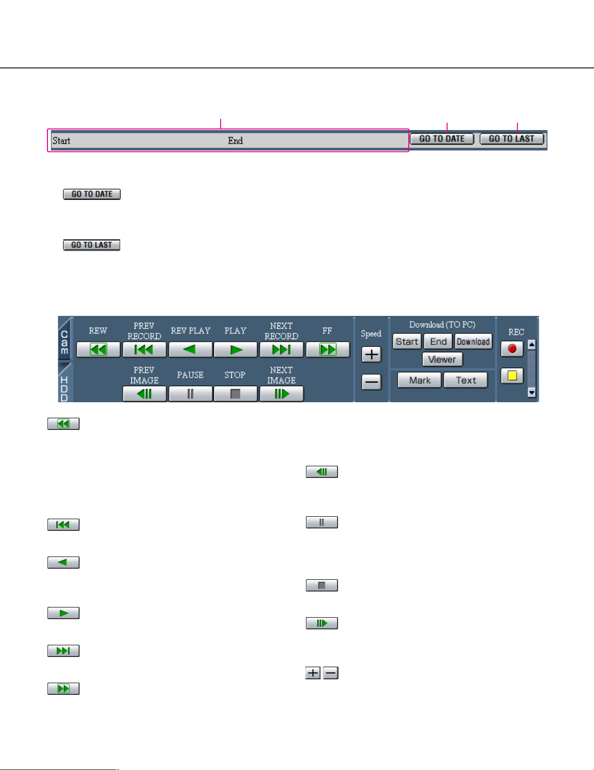
Playback point operation area
q Indicates the start time and the end time of a download. (Refer to the Network Operating Instructions (PDF).)
w [GO TO DATE] button
Indicates the time and date of a marked point. Use this button to designate the desired time and date of a recorded image to be played. (Refer to the Network Operating Instructions (PDF).)
e [GO TO LAST] button
Skips to the latest recorded time of a recorded image from the currently displayed camera channel and plays it.
[HDD] tab
[REW] button
Fast reverse playback will be performed. Playback
speed for fast reverse playback will be changed in the
following order each time this button is clicked: Step2
(approx. 4x) → Step3 (approx. 8x) →
Step4 (approx. 16x) → Step5 (approx. 32x) →
Step6 (approx. 48x) → Step7 (approx. 96x)
[PREV RECORD] button
Skips to the previous recorded image and plays it.
[REV PLAY] button
Reverse playback of a recorded image will be performed.
[PLAY] button
Playback of a recorded image will be performed.
[NEXT RECORD] button
Skips to the next recorded image and plays it.
[FF] button
Fast playback will be performed. Playback speed for
fast playback will be changed in the following order
each time this button is clicked:
Step2 (approx. 4x) → Step3 (approx. 8x) →
Step4 (approx. 16x) → Step5 (approx. 32x) →
Step6 (approx. 48x) → Step7 (approx. 96x)
[PREV IMAGE] button
The previous frame will be displayed when this button is
clicked during pausing.
[PAUSE] button
Playback will be stopped when this button is clicked during playback. Playback will be resumed when this button is clicked during pausing.
[STOP] button
Stops playback and displays a live image.
[NEXT IMAGE] button
The next frame will be displayed when this button is
clicked during pausing.
[Speed] button
The refresh interval will be shortened/lengthened by
clicking these buttons during playback.
q
w e
Page 18
18
[Download (TO PC)] box
Downloads the image currently playing to a PC.
Sets the time range of the desired image to be downloaded by clicking the [Start] button and the
[End] button.
The start time and the end time for download will be displayed in the playback point operation area.
The dialog window for saving an image to be downloaded onto a designated location will be displayed by
clicking the [Download] button.
[Viewer] button
The viewer software can be downloaded by clicking this
button. (Refer to the Network Operating Instructions
(PDF).)
[Mark] button
Mark by clicking this button during playback. When
marked, playback after searching for the marked point is
available. (Refer to the Network Operating Instructions
(PDF).)
[Text] button
The attached text information will be displayed when
this button is clicked during pausing.
It is possible to edit the displayed text information.
[REC] box
The recording button and the recording stop button will
be displayed when the button is clicked.
Displaying the recording button and the recording stop
button will be unavailable when the button is clicked.
[Recording] button: Starts manual recording.
[Stop recording] button: Stops manual
recording.
Notes:
• It is possible to select whether to switch between all
channels, or to select the channel currently displayed in the web browser window to be selected for
manual recording, by performing the settings.
• To display the [Recording] button and the [Stop
recording] button, hold down the button until they
are displayed.
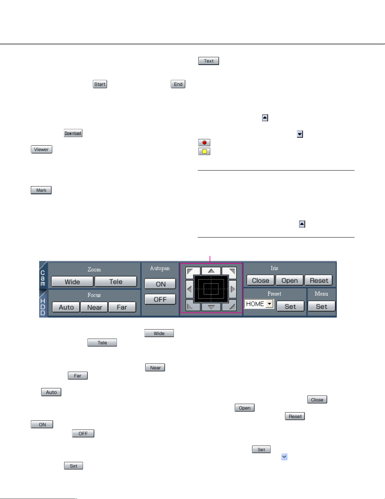
[Cam] tab
[Zoom] box
Zooming can be adjusted by clicking the
[Wide] button or the [Tele] button.
[Focus] box
Focusing can be adjusted by clicking the [Near]
button or the [Far] button.
The auto focus function can be performed by clicking
the [Auto] button.
[Autopan] box
The auto function of the camera will start by clicking the
[ON] button. The auto function can be stopped
by clicking the [OFF] button.
[Menu] box
The settings menu of the camera will be displayed by
clicking the [Set] button.
Control pad
Clicking the buttons around the control pad can move
(pan/tilt) a camera in the clicked direction.
Clicking inside the control pad also can adjust the vertical/horizontal position (pan/tilt) of the displayed image.
Panning/tilting speed will be faster if a clicked point gets
farther from the center point of the control pad.
[Iris] box
The iris can be adjusted by clicking the [Close]
button or the [Open] button. It is possible to
reset the set iris by clicking the [Reset] button.
[Preset] box
Moves a camera to the preset position registered in
advance. Click the [Set] button after selecting a
preset number by clicking the button.
Registering preset positions is required to perform the
preset function.
Control pad
Page 19
19
Setup
Performing each setting item on the setup menu should be completed in advance to operate this unit.
Using the setup menu (Quick) and the setup menu (Advanced)
First, check the settings items of the setup menu (Quick) and perform the settings. When more detailed settings are
required, perform the settings on the setup menu (Advanced).
Refer to page 30 for descriptions about the setup menu (Advanced).
The following are available on the setup menu (Quick).
Setup menu (Quick) chart
Basic operation with the setup menu (Quick)
Screenshot 1
Start operation after the top menu is displayed.
Step 1
Click the [Setup] tab.
Setup menu Description Page
System
Display Setup Perform the display settings such as the display position of the camera
title and time, and the settings for other basic operations of this unit.
REC & Event Setup Perform the basic settings for recording and alarm operation.
Network Setup Perform the basic network settings.
21
24
28
Page 20
20
Screenshot 3
The settings page of the selected menu will be displayed in the image display area.
Step 3
Perform the settings for each item.
Click the [SET] button after completing the settings.
When the [CLEAR] button is clicked, the contents of the
settings will be cleared.
Step 4
To complete the settings menu, click the [Registration]
button.
The settings will be applied.
Important:
• If the settings are applied, all login users will be
forcibly logged out.
• The settings will not be applied by clicking the [SET]
button in step 3. To apply the settings, click the
[Registration] button on the setup menu (Quick).
Screenshot 2
The setup menu (Quick) will be displayed.
Step 2
Click an item on the setup menu (Quick).
Note:
When "ADVANCED" is selected for "REC Type" of
"REC & Event Setup" on the setup menu "Quick"
(page 25), the setup menu (Advanced) will be displayed when the setup tab is clicked. In this case,
click "Quick Setup Menu".
Page 21
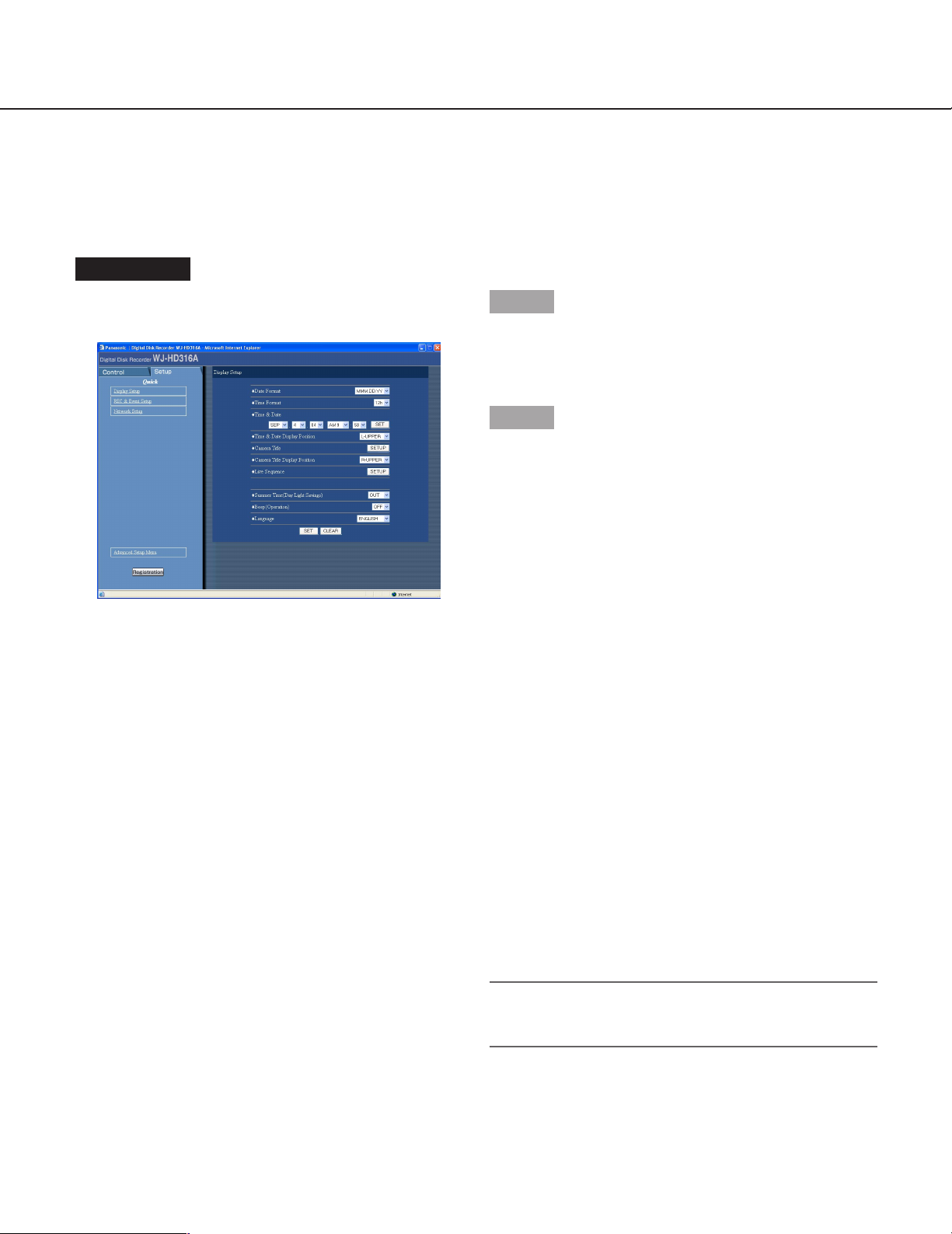
21
Screenshot 1
Start operation after the setup menu (Quick) is displayed by clicking the [Setup] tab. (page 20)
Step 1
Perform the settings for each item.
Refer to the following for further information about the
settings for each item.
Step 2
Click the [SET] button after completing the settings.
Setup items
■ Date Format
Select a display format for the date from the following.
(Ex. April 1, 2003)
YY.MMM.DD: 03.4.1
MMM.DD.YY: APR.1.03
DD.MMM.YY: 1.APR.03
■ Time Format
Select a display format for the time from the following.
(Ex. 3 o’ clock in the afternoon)
12h: 3:00:00 PM
24h: 15:00:00
■ Time & Date
Adjust the current time and date.
Enter year, month, day, hour, minute and second in
order, move the cursor to "SET" and click the SET button.
Important:
Recording will stop for around 4 seconds just after
setting the date and time.
[Display Setup]
Perform the time and date, display settings such as the time and date display, the camera title display, the sequential display and the language setting.
Page 22
22
■ Time & Date Display Position
Select a time and date display position from the following.
L-UPPER: Displays the time at the upper left of the
screen.
R-UPPER: Displays the time at the upper right of the
screen.
L-LOWER: Displays the time at the lower left of the
screen.
R-LOWER: Displays the time at the lower right of the
screen.
Notes:
• The selected position will be the time and date display position on monitor 1.
• When setting the time and date to be recorded
together with images, the time display will be recorded in the selected position.
• Refer to page 52 for further information about
"Embedded REC (Time & Date)".
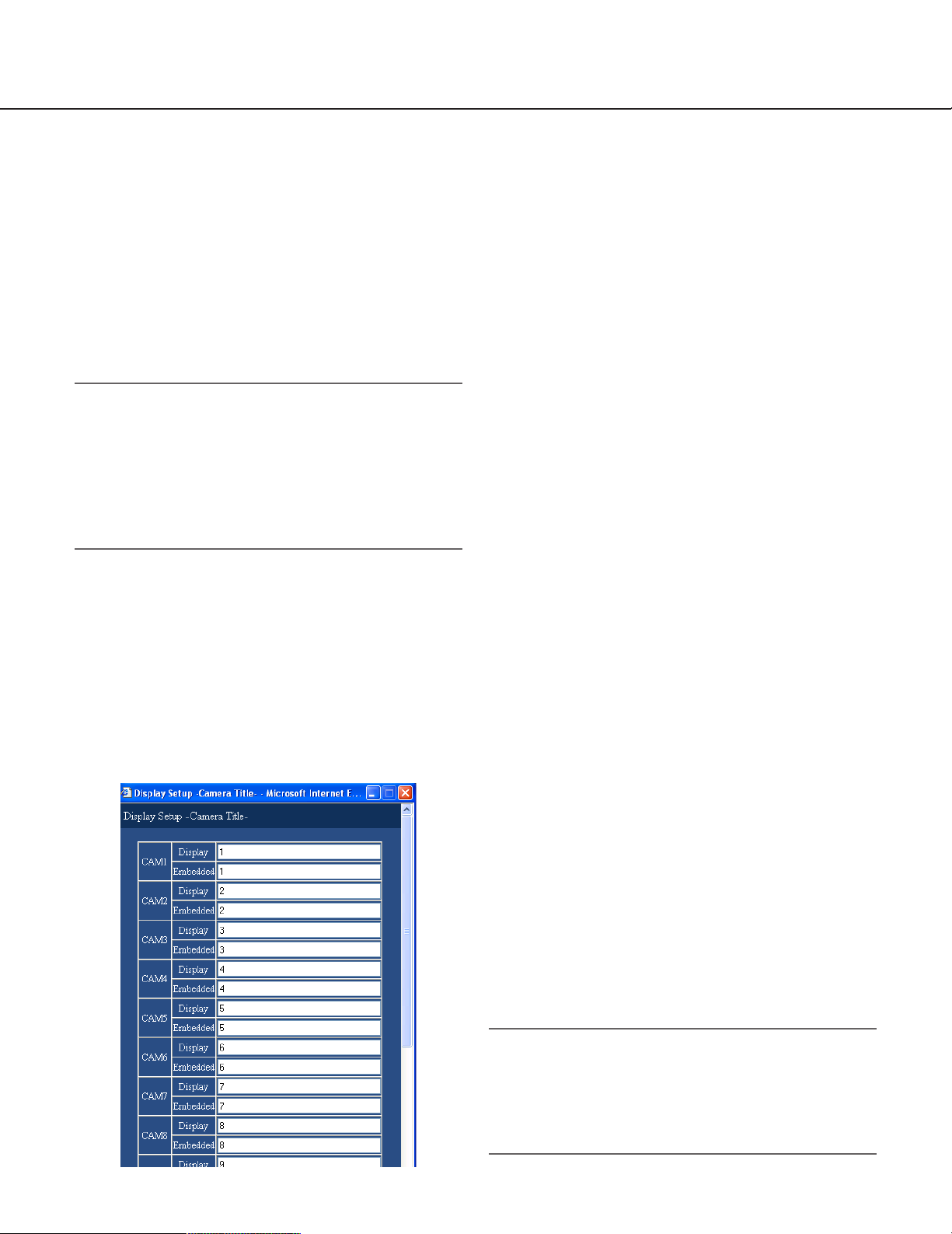
■ Camera Title
Perform the settings for the camera title.
The following window will be displayed when the
[SETUP] button is clicked. Perform the settings for each
item.
Click the [SET] button after completing the settings, and
close the window by clicking the [×] button at the top
right of the window.
[Display]
Enter a camera title to be displayed on monitor 2.
Enter up to 16 alphanumeric characters for a camera
title. However, a part of the camera title may not be displayed when displaying images on a 16-split screen. It
is recommended to enter up to 8 alphanumeric characters for each camera title.
[Embedded]
Enter a camera title to be embedded together (recorded
with images) and to be displayed when "ON" is selected
for "Embedded REC (Title)" on "Recording Setup" of
"Recording" menu and also for displaying camera titles
on monitor 1 (page 51). Enter up to 16 alphanumeric
characters for a camera title.
The available characters for a camera title are different
depending on the selected language as follows.
<When any language except RUSSIAN is selected>
0 1 2 3 4 5 6 7 8 9 A B C D E F G H I J K L M N O P Q
R S T U V W X Y Z a b c d e f g h i j k l m n o p q r s t u
v w x y z À Ä Â Æ Ç É Ì Ñ Ò Ö Ù Ü Ø ß à á â ä å æ ç è
é ê ë ì í î ï ñ ò ó ô ö ù ú û ü ø ? " # & ( ) * + , - . / : ; SP
<When RUSSIAN is selected>
0123456789ABCDEFGHIJKLMNOPQRSTUVW
XYZabcdefghijklmnopqrstuvwxyzДЕЗЙСЦ›
Ьбавдгезйиклнмопсутфцхъщыь?"#
&()*+,-./:;SP
■ Camera Title Display Position
Select a camera title display position from the following.
L-UPPER: Displays the camera title at the upper left of
the screen.
L-LOWER: Displays the camera title at the lower left of
the screen.
R-UPPER: Displays the camera title at the upper right
of the screen.
R-LOWER: Displays the camera title at the lower right
of the screen.
CENTER: Displays the camera title at the center of the
screen.
Note:
When setting the camera title to be recorded together with images, the camera title display will be
embedded in the selected position.
Refer to page 51 for further information about
"Embedded REC (Title)".
Page 23

■ Live Sequence
Perform the settings for the sequential display of live
images. The following window will be displayed when
the [SETUP] button is clicked. Perform the settings for
each item. Click the [SET] button after completing the
settings, and close the window by clicking the [×] button
at the top right of the window.
[CAM]
Select a camera image to be displayed at each step.
--: Skips the selected step.
CAM1 - 16: Displays an image from the selected cam-
era channel on a single screen.
QUAD1 - 4: Displays images from camera channels 1 -
4 on a 4-split screen.
QUAD5 - 8: Displays images from camera channels 5 -
8 on a 4-split screen.
QUAD9 (only for the WJ-HD309A): Displays an image
from camera channel 9 on the upper left area on a
4-split screen.
QUAD9 - 12 (only for the WJ-HD316A): Displays
images from camera channels 9 - 12 on a 4-split
screen.
QUAD13 - 16 (only for the WJ-HD316A): Displays
images from camera channels 13 - 16 on a 4-split
screen.
9SCREEN (only for the WJ-HD309A): Displays images
from camera channel 1 - 9 on a 9-split screen.
9SCREEN1 - 9 (only for the WJ-HD316A): Displays
images from camera channels 1 - 9 on a 9-split
screen.
9SCREEN10 - 16 (only for the WJ-HD316A): Displays
images from camera channels 10 - 16 on a 9-split
screen.
23
[PRESET POSITION]
Select a camera position from the following.
1 - 256: Moves to the selected preset position.
--: Does not move to any of the preset positions.
[DWELL]
Select an interval time to go to the next sequential step
from 1 - 30 seconds (in 1 second intervals).
■ Summer Time (Day Light Saving)
Select the method of switching to summer time from the
following.
OUT: Does not function.
IN: Applies summer time.
AUTO: Applies summer time in accordance with the set-
ting of summer time.
■ Beep (Operation)
Select ON or OFF whether or not to sound the buzzer
when operating the buttons.
ON: Sounds the buzzer when operating the buttons.
OFF: Does not sound the buzzer when operating the
buttons.
■ Language
Select a language for the SETUP MENU from the following.
JAPANESE/ENGLISH/FRANÇAIS/ESPAÑOL/
DEUTSCH/ITALIANO/RUSSIAN/CHINESE
Important:
Displaying the language of the browser used to
access the unit from a PC will not be changed even
though this setting is changed.
Page 24
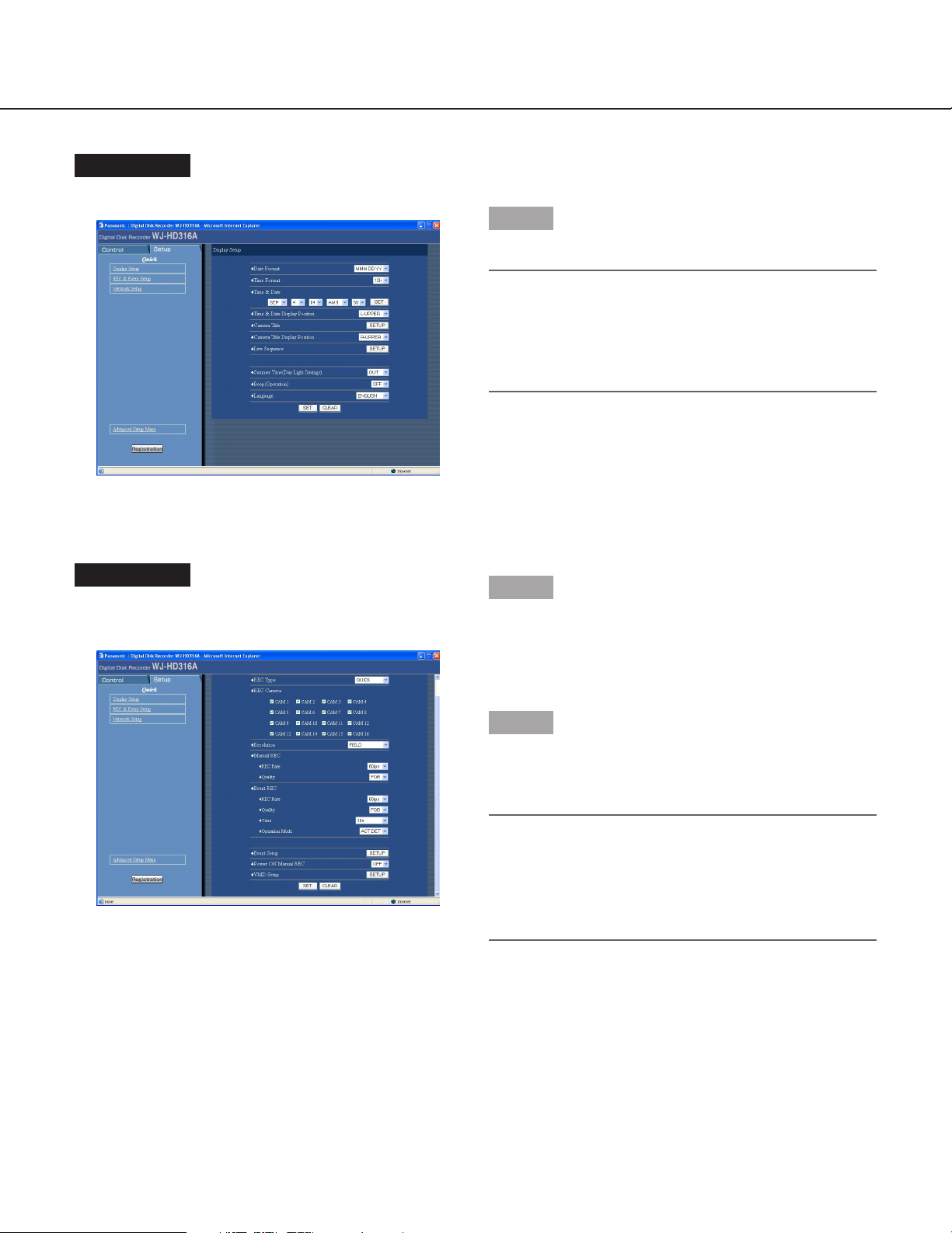
24
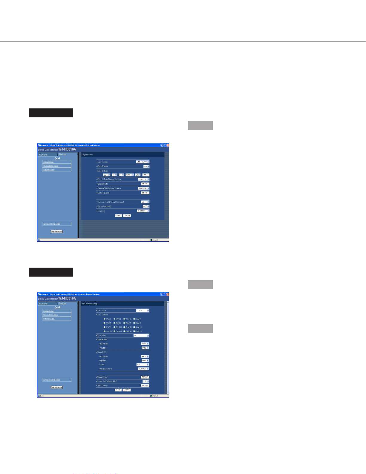
[REC & Event Setup]
Perform the settings for the basic recording and the settings for event actions of each event type (motion detection,
video loss, command alarm and terminal alarm.)
Screenshot 1
Start operation after the setup menu (Quick) is displayed by clicking the [Setup] tab. (page 20)
Step 1
Click "REC & Event Setup".
Screenshot 2
The "REC & Event Setup" menu will be displayed.
Step 2
Perform the settings for each item.
Refer to the following for further information about the
settings for each item.
Step 3
Click the [SET] button after completing the settings.
Page 25

25
Setup items
■ REC Type
Select "QUICK" or "ADVANCED" for validation of the
recording settings.
QUICK: The recording settings set on the setup menu
(Quick) will be validated when recording.
ADVANCED: The recording settings set on the setup
menu (Advanced) will be validated when recording.
■ REC Camera
Select a camera channel for manual recording/event
recording by checking the checkbox next to the desired
camera.
■ Resolution
Select a recording resolution from the following.
FRAME 3D ON: High resolution (720 x 480), with cam-
era shake compensation
FRAME 3D OFF: High resolution (720 x 480)
FIELD: Standard resolution (720 x 240)
SIF: Low resolution (360 x 240)
Notes:
• Recording will not be performed for around 4 seconds when the setup menu (Quick) is closed after
changing the settings.
• It is possible to minimize blurring to record fast moving objects by selecting "FRAME 3D ON".
■ Manual REC
Perform the recording rate (REC Rate) and the image
quality (REC Quality) for manual recording.
The following are available for the recording rate.
OFF/2 ips/3 ips/5 ips/6 ips/7.5 ips/10 ips/15 ips/30
ips/60 ips/120 ips
Note:
The camera channel number selected for "REC
Camera" will be displayed next to the selected
recording rate.
The following are available for the image quality.
SFA/SFB: Top quality (SUPER FINE)
FQA/FQB: High quality (FINE)
NQA/NQB: Standard quality (NORMAL)
EXA/EXB: Low quality (EXTENDED)
**A is suitable for less dynamic images.
**B is suitable for more dynamic images.
■ Event REC
Perform the recording rate (REC Rate) and the image
quality (REC Quality) for event recording (recording to
be performed at event occurrence (motion detection,
video loss, command alarm and terminal alarm)).
The following are available for "REC Rate" (recording
rate).
OFF/2 ips/3 ips/5 ips/6 ips/7.5 ips/10 ips/15 ips/30
ips/60 ips/120 ips
Note:
The camera channel number selected for "REC
Camera" will be displayed next to the selected
recording rate.
The following are available for "REC Quality" (image
quality).
SFA/SFB: Top quality (SUPER FINE)
FQA/FQB: High quality (FINE)
NQA/NQB: Standard quality (NORMAL)
EXA/EXB: Low quality (EXTENDED)
**A is suitable for less dynamic images.
**B is suitable for more dynamic images.
Page 26

26
The following are available for "Time" (recording duration).
1 s - 10 s (in 1 second intervals)/20 s/30 s/
1 min - 10 - min (in 1 minute intervals)/20 min/
30 min/40 min/ 50 min/ 60 min
MANUAL: Recording duration differs depending on the
event type as follows;
When motion is detected: Recording will be performed for 8 seconds
When video loss has occurred: Recording will be
performed while the video signal is lost.
When a terminal alarm has occurred: Recording
will be performed during the alarm signal is being
supplied.
When a command alarm has occurred: Recording
will be performed for 8 seconds.
CONTINUE: Record until the ALARM RESET button is
pressed
When "MANUAL" is selected for "Time" (recording duration), recording will be performed for at least 8 seconds
at an event occurrence as long as the alarm is not canceled.
The following are available for "Operation Mode" (event
action mode). Refer to the Network Operating
Instructions (PDF) for further information about each
event action mode.
ACT DET (Activity Detection Mode): Performs only
recording and writing an event log at an event occurrence. Other event actions will not be performed.
ALARM (Alarm Mode): Performs recording, writing an
event log, supplying the alarm output and sounding
the buzzer according to the settings for "Event
Setup".
OFF: Performs only recording of the event log. Other
event actions will not be performed.
■ Event Setup
Perform the settings for the alarm output duration and
the buzzer sound duration for each event type (motion
detection, video loss, command alarm and terminal
alarm).
The following window will be displayed when the
[SETUP] button is clicked. Perform the settings for each
item.
Click the [SET] button after completing the settings, and
close the window by clicking the [×] button at the top
right of the window.
The following are available for "Alarm Output" (alarm
output duration).
When OFF is selected, the alarm output will not be supplied.
(s: second)
OFF: No alarm output is supplied.
1 s - 30 s (in 1 second intervals)/40 s/50 s/1 min/
2 min/3 min/4 min/5 min
EXT: Alarm output will continue until the ALARM
RESET button is pressed.
The following are available for "Buzzer" (buzzer sound
duration).
When OFF is selected, a buzzer will not sound.
(s: second)
OFF: The buzzer will not sound.
1 s - 30 s (in 1 second intervals)/40 s/50 s/1 min/
2 min/3 min/4 min/5 min
EXT: The buzzer will continue until the ALARM RESET
button is pressed.
Page 27

27
■ Power ON Manual REC
Select ON or OFF to determine whether or not to start
recording when the power is turned on by the connected
external timer (or the switch).
ON: Manual recording will start automatically after com-
pleting the system check.
OFF: Manual recording will not start automatically after
completing the system check.
Important:
When ON is selected, manual recording will start
automatically after completing the system check.
■ VMD Setup
Select ON or OFF to determine whether to enable or
disable the motion detection function for each camera
channel.
When ON is selected, perform the settings for the
motion detection area for each camera channel. Up to 4
areas can be set for a camera channel for the detection
area. Refer to the Network Operating Instructions (PDF)
for further information about the motion detection function.
The following window will be displayed when the
[SETUP] button is clicked. Perform the settings for each
item.
Click the [SET] button after completing the settings, and
close the window by clicking the [×] button at the top
right of the window.
Select ON for the desired camera channel and press
the SET button. Then, click the respective [SETUP] button for the desired camera channel to be set. The following window will be displayed.
Set the motion detection areas by dragging the mouse.
Up to 4 areas (A, B, C, D) can be set for the detection
areas.
A: White
B: Blue
C: Green
D: Red
Click the [SET ALL AREA] button to set all areas on the
monitor as the motion detection area.
To delete a detection area, click the [DELETE AREA]
button after selecting a detection area by checking the
check box of the desired area to be deleted.
Click the [SET] button after completing the settings, and
close the window by clicking the [×] button at the top
right of the window.
Notes:
• Refer to page 58 for descriptions of how to delete
the motion detection area.
• It is possible to set the sensitivity and the detection
mode (method of detection) for each detection area.
Refer to page 58 for further information.
Page 28

Screenshot 2
The "Network Setup" menu will be displayed.
Step 2
Perform the settings for each item.
Refer to the following for further information about the
settings for each item.
Step 3
Click the [SET] button after completing the settings.
28
Screenshot 1
Start operation after the setup menu (Quick) is displayed by clicking the [Setup] tub. (page 20)
Step 1
Click "Network Setup".
[Network Setup]
Perform the settings for the network such as the IP address and the gateway address when operating this unit using
a PC via a network such as a LAN.
Page 29

29
Setup items
■ Line Speed
The following are available for "Line Speed".
AUTO: Line speed will be applied automatically.
10-HALF: 10 Mbps half duplex
10-FULL: 10 Mbps full duplex
100-HALF: 100 Mbps half duplex
100-FULL: 100 Mbps full duplex
Note:
When the setup menu is closed after changing the
line speed, the unit will automatically restart.
■ HTTP Port Number
Specify the HTTP port number to be used to transfer
images from this unit. It is not necessary to change it for
normal use.
Notes:
• Depending on the network settings of the LAN or
Internet service provider, network communication
may not be established if the http port number has
been changed.
• The following port numbers are unavailable for the
HTTP port number:
20, 21, 23, 25, 42, 67, 68, 69, 79, 105, 110, 123,
161, 162, 10000, 10001, 10002, 10003, 10004,
10005, 10006, 10007
■ DHCP
Select ON or OFF for whether or not to use the DHCP
server. When obtaining IP addresses, net mask and a
gateway address from the DHCP server, set to ON.
If not, set to OFF and enter those addresses manually.
ON: Uses the DHCP server.
OFF: Does not use the DHCP server.
■ IP Address
Enter an IP address when OFF is selected for "DHCP".
For this unit, enter 4 units from the decimal numbers (0-
254).
■ Subnet Mask
Enter a subnet mask according to the network configuration when OFF is selected for "DHCP".
■ Gateway
Enter the gateway address according to the network
configuration when OFF is selected for "DHCP".
Page 30

30
Setup menu Description Page
System
Basic Setup Settings for basic operations of this unit can be performed.
Time & Date Setup Settings for the current time and for displaying the time and date
can be performed.
User Registration Set this item for user registration and user authentication. User
name, password and operational level can be set.
User Edit/Delete Correction or deletion of user information can be performed.
Host Registration Set this item for the host authentication by registering PCs
(hosts) allowed to access this unit via a network. Operational lev-
els and IP addresses of PCs can be set.
Host Edit/Delete Correction or deletion of host information can be performed.
User Level Setup Functions operable in each user level can be set.
Save/Load Contents of settings for this unit will be saved or loaded.
Recording
Recording Setup Basic recording setup can be performed with this menu.
Emergency REC Settings for emergency recording such as the recording time and
recording rate can be performed on this menu.
Event
Event Setup Settings for an event action can be performed with this menu.
VMD Setup Settings for the motion detection area, sensitivity and detection
mode can be performed for each camera channel.
Alarm Setup Settings for the duration of alarm display and alarm mask can be
performed with this menu.
Terminal Setup The alarm terminal polarity can be set with this menu.
Schedule
REC Program Create recording programs on this menu. Up to 4 programs can
be created. Settings for recording actions such as the image
quality or recording rate for each camera channel can be per-
formed for each program with this menu.
Event Program Create event programs. Up to 4 programs can be created.
Settings for action mode and camera action can be performed for
each event type.
35
38
41
43
44
46
47
49
50
53
55
57
60
61
62
66
Setup menu (Advanced) chart
Page 31

31
Setup menu Description Page
Schedule
Time Table Make timetables of operation for each day of the week, and
assign recording action programs and event action programs to
each timetable.
Special Days Assign timetables for special days apart from other days of the
week.
Switcher
Monitor 1 Settings for the image switching such as the sequential operation
or for displaying the login window on monitor 1 can be per-
formed.
Monitor 2 Settings for the image switching such as the sequential operation
or for displaying the login window on monitor 2 can be per-
formed.
Network Settings for the image switching of the PC monitor connected to
this unit via a network can be performed.
Display
OSD Setup Settings for the display position of the camera title or time can be
performed.
Monitor 1 Perform the display settings for monitor 1 such as time display,
camera title display and alarm display.
Monitor 2 Perform the display settings for monitor 2 such as task bar style,
time display position and camera title display.
Comm
Camera Control Setting for the communication method to control cameras for
each camera channel can be performed.
PS.Data Setup Settings for PS·Data can be performed. Set this item when con-
necting an external device such as a controller to the DATA port
on the rear panel.
RS485 Setup Settings for RS485 can be performed. Set this item when con-
necting a camera to the RS485 port on the rear panel.
RS232C Setup Settings for SERIAL (RS232C) can be performed. Set this item
when connecting a PC to the serial terminal on the rear panel.
Network Setup 1 Settings for a network can be performed. Set this item when
operating this unit via a network such as a LAN. User authentica-
tion and host authentication can be set with the network basic
settings.
Network Setup 2 Settings for a network connection such as settings of the IP
address and gateway address can be performed. Set this item
when operating this unit via a network such as a LAN.
69
72
73
76
77
79
82
83
84
86
88
90
92
94
Page 32

32
Setup menu Description Page
Network SNMP Setup Settings for SNMP can be performed. Set this item to check the
status of the server by connecting to the SNMP server.
Network NTP Setup Set this item when adjustment of the time is required to be set
with the NTP server such as when setting the NTP server
address or time zones.
Network FTP Setup Settings for the FTP server can be performed. Settings for trans-
mitting images from a camera connected to this unit to a desig-
nated FTP server periodically can be performed with the Network
FTP Setup menu.
Network Mail Setup Set this item to send e-mails to addresses registered in advance
at an event occurrence.
Panasonic Alarm Protocol It is possible to send a message to addresses registered in
advance using "Panasonic Alarm Protocol" when an event or a
problem occurs. To receive messages using this function, the
optional software is necessary.
Maintenance
REC Rate Status Recording rate in each recording mode and image quality for
each camera channel will be displayed in list form.
Disk Information Hard disk information such as available capacity of the built-in
hard disk or an extension unit will be displayed.
96
97
98
101
103
104
105
Version Information Version information of the software and hardware, and MAC
address will be displayed.
Disk End Mode Perform the settings for action when running out of hard disk
space.
Disk Capacity If the available hard disk/external recording device capacity
reaches a specified level, a warning will be displayed.
Data Delete Data on the hard disk/external recording device will be deleted.
The DVD-RAM disk connected to the copy port on the rear panel
of this unit will be formatted (initialized).
106
107
108
109
Page 33

33
Basic operation with the setup menu (Advanced)
Screenshot 1
Start operation after the top menu is displayed.
Step 1
Click the [Setup] tab.
Screenshot 2
The setup menu (Advanced) will be displayed.
Step 2
Click a button on the setup menu (Advanced).
Note:
When "QUICK" is selected for "REC Type" of "REC
& Event Setup" (page 25), the setup menu (Quick)
will be displayed by clicking the [Setup] tab. In this
case, it is possible to display the setup menu
(Advanced) by clicking "Advanced Setup Menu".
Main menu
Page 34

34
Screenshot 3
The submenus respective to the clicked button on the
setup menu (Advanced) will be displayed.
Step 3
Click the desired submenu on the setup menu
(Advanced).
Submenu
Screenshot 4
The settings page of the selected submenu will be displayed in the image display area.
Step 4
Perform the settings for each item.
Click the [SET] button after completing the settings.
When the [CLEAR] button is clicked, the contents of the
settings will be cleared.
Step 5
To complete the settings, click the [Registration] button.
The settings will be applied.
Important:
• If the settings are applied, all login users will be
forcibly logged out.
• The settings will not be applied by clicking the [SET]
button in step 4 yet. To apply the settings, click the
[Registration] button on the setup menu (Advanced).
Page 35

35
Screenshot 1
Start operation after the submenu of the system menu is
displayed by clicking the [System] button in the setup
menu (Advanced). (page 15)
Step 1
Click "Basic Setup".
Screenshot 2
The "Basic Setup" menu will be displayed.
Step 2
Perform the settings for each item.
Refer to page 36 for further information about the settings for each item.
Step 3
Click the [SET] button after completing the settings.
Perform the settings for the system [System]
Perform the settings for the system of this unit.
Perform the basic settings for the system [Basic Setup]
Perform the settings for the basic operations of this unit.
Page 36

36
■ ADMIN Password
Set a password for an administrator.
Enter 4 to 8 alphanumeric characters.
Important:
To enhance the security, change the password for
an administrator periodically.
■ PSD User
Perform the settings for a user when using a PS·Data
compatible controller. A PSD user should be one of the
registered users for this unit.
■ Auto Login
Select ON or OFF to determine whether to activate or
deactivate the auto login function.
OFF: Deactivate the auto login function. Authentication
will be required each time this unit starts up.
ON: Activates the auto login function.
■ Auto Login User
When ON is selected for "Auto Login", the user registered as auto login user in this setting can log into the
unit automatically.
An auto login user should be one of the users registered
in this unit.
■ Auto Logout
Perform the settings to log out a user automatically
when the set time has passed from the time a user
logged in.
OFF: Deactivate the auto logout function.
1/2/3/4/5/30 min: Activates the auto logout function
after the selected time has passed from the time a
user logged in.
Important:
When ON is selected for the auto login function, the
auto logout function will not work.
■ Priority
Perform the settings to assign priorities to operate this
unit in case two or more users access this unit simultaneously.
A priority is followed.: Users with higher priority can
operate this unit.
Pre-priority: The user who accessed the unit first can
operate it regardless of the priorities.
Post-priority: The user who accessed the unit last can
operate it regardless of the priorities.
■ "GO TO LAST" before
Select a time to be skipped to when the [GO TO LAST]
button is pressed during playback from the following.
5 s/10 s/30 s/1 min/5 min
■ Language
Select a language for the SETUP MENU from the following.
JAPANESE/ENGLISH/FRANÇAIS/ESPAÑOL/
DEUTSCH/ITALIANO/RUSSIAN/CHINESE
Important:
The displaying language of the browser used to
access the unit from a PC will not be changed even
though this setting is changed.
■ Beep (Operation)
Select ON or OFF to determine whether or not to sound
the buzzer when the button is pressed.
■ Buzzer (Error)
Perform the settings for sounding a buzzer at an error
occurrence.
OFF: A buzzer will not sound at an error occurrence.
1 s - 30 s (in 1 second intervals)/40 s/50 s/1 min/3 min/
4 min/5 min (in 1 minute intervals):
The buzzer that started sounding at an error occurrence will sound for the selected period.
EXT: The buzzer that started sounding at an error
occurrence will keep on sounding until the [ALARM
RESET] button on the front panel of the unit is
pressed or the [ALARM RESET] button in the status
display area is clicked.
Setup items
Page 37

37
■ Shutdown Time
Determine when the safe shutdown starts after a power
outage alert signal is supplied to this unit.
10 s/20 s/30 s/1 min/2 min/3 min/4 min/5 min
■ Auto Copy
Perform the settings to copy recorded images automatically to the copy area of the hard disk or the DVD-RAM
disk.
OFF: Images will not be copied.
COPY1: Images will be copied to the DVD-RAM disk
connected to the copy 1 port.
COPY1 (ALT): Copies recorded images with an alter-
ation detection code using the viewer software to the
DVD-RAM disk connected to the COPY1 port.
COPY2: Images will be copied to the DVD-RAM disk
connected to the copy 2 port.
COPY2 (ALT): Copies recorded images with an alter-
ation detection code using the viewer software to the
DVD-RAM disk connected to the COPY2 port.
HDD: Images will be copied to the copy area of the hard
disk of this unit.
Important:
• When "OFF" is selected, the auto copy function will
be disabled even for an emergency recording and
auto copy at an event occurrence.
• Auto copy will not function without connecting to a
DVD-RAM disk even if "COPY1" or "COPY2" is
selected.
• Images recorded (by pre-event recording) in the prerecording area on the hard disk will not be copied
automatically.
• When emergency recording/event recording are performed frequently, it may be possible that the auto
copy function does not function.
• Images to be copied automatically will be 30
minute’s worth of images recorded from the start of
emergency recording/event recording.
Page 38

38
Screenshot 1
Start operation after the submenu of the system menu is
displayed by clicking the [System] button in the setup
menu (Advanced). (page 15)
Step 1
Click "Time & Date Setup".
Screenshot 2
The "Time & Date Setup" menu will be displayed.
Step 2
Perform the settings for each item.
Refer to page 39 for further information about the settings for each item.
Step 3
Click the [SET] button after completing the settings.
Perform the settings for the time and date [Time & Date Setup]
Perform the settings for the time and date.
Page 39

39
■ Date Format
Select a date format to be displayed from the following.
(Example for April 1, 2004)
YY.MM.DD: 04.4.1
MMM.DD.YY: APR.1.04
DD.MMM.YY: 1.APR.04
■ Time Format
Select a time format to be displayed from the following.
(Example for 3 o’clock in the afternoon)
24 h: 15:00:00
12 h: 3:00:00 PM
■ Time & Date
Adjust the current time and date.
Enter numbers in order for the year, month, day, hour
and minute, and then click the [SET] button.
Important:
Recording will stop for around 4 seconds just after
setting the clock.
■ Auto Adjust Time
Select a method of auto clock adjustment from the following.
When "MASTER" is selected, signals will be supplied
from the ALARM/CONTROL connector to inform the
clock of the MASTER unit (see below) at a set time.
OFF: Does not adjust time automatically.
SLAVE: Receives a signal from the MASTER unit and
adjusts the clock.
MASTER: Supplies a from the ALARM/CONTROL con-
nector on the rear panel signal to the other connected devices and the other devices will adjust their
clocks with reference to the clock of this unit.
Important:
• Recording will not be performed for around 4 seconds when changing the present time (accurate
within ±5 seconds) using the time adjustment input
(pin no.20).
• The clock will not be adjusted automatically during
the post-event recording or emergency recording.
■ Time
When "MASTER" is selected for "Auto Adjust Time", set
the clock for a signal to be supplied from the ALARM/
CONTROL connector (time adjustment I/O, pin. no. 20)
of the ALARM/CONTROL connector on the rear panel
of the unit.
When "SLAVE" is selected, set the time when the unit
receives a signal from the MASTER unit and adjust the
clock.
Important:
When "MASTER" or "SLAVE" is selected, it is
required to apply the same time to the MASTER unit
and the SLAVE unit to adjust the clock automatically.
■ Summer Time (Day Light Savings)
Perform the settings for summer time from the following.
OUT: Does not apply summer time.
IN: Applies summer time.
AUTO: Applies summer time automatically in accor-
dance with the settings for switching to summer time
(Refer to the following).
Setup items
Page 40

40
■ Summer Time (Day Light Savings) Table
Set the start (ON)/end (OFF) date and time for summer
time.
The following window will be displayed when the
[SETUP] button is clicked. Click the [SET] button after
completing the settings, and close the window by clicking the [×] button at the top right of the window.
Enter the last 2 digits of the year.
Up to 10 times and dates for switching to summer time
can be set.
Page 41

41
Screenshot 2
The "User Registration" menu will be displayed.
Step 2
Perform the settings for each item.
Refer to page 42 for further information about the settings for each item.
Step 3
Click the [SET] button after completing the settings.
Note:
Repeat steps 2 and 3 to register two or more users.
Screenshot 1
Start operation after the submenu of the system menu is
displayed by clicking the [System] button in the setup
menu (Advanced). (page 15)
Step 1
Click "User Registration".
Registration of a user who operates this unit [User Registration]
Register user information such as a user name and password.
Page 42

42
■ User Name
Enter a user name. Enter 4 to 14 alphanumeric characters for a user name.
■ Password
Enter a password. Enter 4 to 8 alphanumeric characters
for a password.
Important:
Set a unique password, not something that would be
easily guessed by a third person. The password also
should be memorable.
■ Level
Select a user level from the following. Operable functions for each level can be set in "User Level Setup"
menu (page 47).
LV1/LV2/LV3
■ Priority
Assign a priority from 1 (highest priority) to 16 (lowest
priority) to every user.
■ Default Screen
Select a startup display to be displayed after login from
the following.
CAM1-16 (for the WJ-HD316A)/CAM1-9 (for the WJ-
HD309A): Displays live images from the selected
camera channel on a single screen.
QUAD1-4: Displays live images from camera channels
1 - 4 on a 4-split screen.
QUAD5-8: Displays live images from camera channels
5 - 8 on a 4-split screen.
QUAD9 (only for the WJ-HD309A): Displays an image
from camera channel 9 on the upper left area on a
4-split screen.
QUAD9-12 (only for the WJ-HD316A): Displays live
images from camera channels 9 - 12 on a 4-split
screen.
QUAD13-16 (only for the WJ-HD316A): Displays live
images from camera channels 13 - 16 on a 4-split
screen.
7SCREEN: Displays images from camera channels 1 -
7 on a 7-split screen.
9SCREEN (only for the WJ-HD309A): Displays an
image from camera channel 1 - 9 on the upper left
area on a 9-split screen.
9SCREEN1-9 (only for the WJ-HD316A): Displays
images from camera channels 1 - 9 on a 9-split
screen.
9SCREEN10-16 (only for the WJ-HD316A): Displays
images from camera channels 10 - 16 on a 9-split
screen.
10SCREEN (only for the WJ-HD316A): Displays images
from camera channels 1 - 10 on a 10-split screen.
13SCREEN (only for the WJ-HD316A): Displays images
from camera channels 1 - 13 on a 13-split screen.
16SCREEN (only for the WJ-HD316A): Displays images
from camera channels 1 - 16 on a 16-split screen.
SEQ: Images will be displayed in the sequential display.
■ Camera Partitioning
Select a controllable range for each camera channel
from the following.
View & Operate: Both displaying live/recorded images
and controlling cameras are available.
View: Only displaying live/recorded images is possible.
Controlling cameras is not possible.
--: Neither displaying live/recorded images nor controlling cameras are possible.
Setup items
Page 43

43
Screenshot 2
The "User Edit/Delete" menu will be displayed.
Step 2
Click the [i] button to select the desired user information to be edited or deleted.
Step 3
• Click the [EDIT] button to edit the selected user
information.
The "Edit user information" window will be displayed
with information of the registered user. Edit user
information in the same way as the user registration.
(page 41)
• Click the [DELETE] button to delete the selected
user.
Screenshot 1
Start operation after the submenu of the system menu is
displayed by clicking the [System] button in the setup
menu (Advanced). (page 15)
Step 1
Click "User Edit/Delete".
Edit/delete registered user information [User Edit/Delete]
Edit or delete registered user information.
Page 44

44
Screenshot 2
The "Host Registration" menu will be displayed.
Step 2
Perform the settings for each item.
Refer to page 45 for further information about the settings for each item.
Step 3
Click the [SET] button after completing the settings.
Note:
Repeat steps 2 and 3 to register two or more hosts.
Screenshot 1
Start operation after the submenu of the system menu is
displayed by clicking the [System] button in the setup
menu (Advanced). (page 15)
Step 1
Click "Host Registration".
Registration of a PC (host) accessible to this unit [Host Registration]
Register information of a PC (host) that accesses this unit via a network such as a LAN.
Page 45

45
■ Host IP Address
Enter an IP address. Enter 4 units from the decimal
numbers (0-254).
Notes:
• Entering "*" validates all numbers.
• It is impossible to register "0.0.0.0" or "*. *. *. *".
■ Level
Select a level from the following. Operable functions for
each level can be set in "User Level Setup" menu (page
47).
LV1/LV2/LV3
■ Priority
Assign a priority from 1 (lowest priority) to 16 (highest
priority) to every host.
■ Default Screen
Select a startup display to be displayed after login from
the following.
CAM1-16 (for the WJ-HD316A)/CAM1-9 (for the WJ-
HD309A): Displays live images from the selected
camera channel on a single screen.
QUAD1-4: Displays live images from camera channels
1 - 4 on 4-split screen.
QUAD5-8: Displays live images from camera channels
5 - 8 on 4-split screen.
QUAD9 (only for the WJ-HD309A): Displays an image
from camera channel 9 on the upper left area on a
4-split screen.
QUAD9-12 (only for the WJ-HD316A): Displays live
images from camera channels 9 - 12 on a 4-split
screen.
QUAD13-16 (only for the WJ-HD316A): Displays live
images from camera channels 13 - 16 on a 4-split
screen.
7SCREEN: Displays images from camera channels 1 -
7 on a 7-split screen.
9SCREEN (only for the WJ-HD309A): Displays an
image from camera channel 1 - 9 on the upper left
area on a 9-split screen.
9SCREEN1-9 (only for the WJ-HD316A): Displays
images from camera channels 1 - 9 on a 9-split
screen.
9SCREEN10-16 (only for the WJ-HD316A): Displays
images from camera channels 10 - 16 on a 9-split
screen.
16SCREEN (only for the WJ-HD316A): Displays images
from camera channels 1 - 16 on a 16-split screen.
SEQ: Images will be displayed in the sequential display.
■ Camera Partitioning
Select a controllable range for each camera channel
from the following.
View & Operate: Both displaying live images and con-
trolling cameras are possible.
View: Only displaying live images is possible.
Controlling cameras is not possible.
--: Neither displaying live images nor controlling cameras are possible.
Setup items
Page 46

46
Screenshot 2
The "Host Edit/Delete" menu will be displayed.
Step 2
Click the [i] button to select the desired host information to be edited or deleted.
Step 3
• Click the [EDIT] button to edit the selected host
information.
The "Edit host information" window will be displayed
with information of the registered host. Corrections
can be performed in the same way as registration.
(page 44)
• Click the [DELETE] button to delete the selected
host IP address.
Screenshot 1
Start operation after the submenu of the system menu is
displayed by clicking the [System] button in the setup
menu (Advanced). (page 15)
Step 1
Click "Host Edit/Delete".
Edit/delete registered host information [Host Edit/Delete]
Edit or delete registered host information.
Page 47

47
Screenshot 2
The "User Level Setup" menu will be displayed.
Notes:
• Each parameter of user level is as follows:
LV1: Possible to perform all the operations
(Administrators)
LV2: Possible to refer to the settings of the unit and
the access log, and to perform the alarm reset
(Head of operators)
LV3: Possible to monitor or play the images
(Operators)
• The default settings are shown as in the magnified
picture above.
Step 2
Check the desired functions that a user may operate. To
stop a user from operating certain functions, do not
check the respective function.
Refer to the next page for further information about
each function.
Step 3
Click the [SET] button after completing the settings.
Screenshot 1
Start operation after the submenu of the system menu is
displayed by clicking the [System] button in the setup
menu (Advanced). (page 15)
Step 1
Click "User Level Setup".
Setting of operation level [User Level Setup]
Assign a level (LV 1/LV 2/LV 3) to every user to restrict operable functions.
Page 48

48
Functions that can be restricted
The following functions can be restricted according to the user levels.
Function Description
Setup The SETUP MENU is displayed and the settings can be performed.
Setup Status Only the SETUP MENU can be displayed. The settings cannot be
performed.
Camera Setup The settings menu of the camera is displayed and the settings can
be performed.
Event Log Status The SETUP MENU is displayed and you can refer to the event log.
(Refer to page 14.) You also can refer to the network log. Refer to
the Network Operating Instructions (PDF) for further information.
Access Log Status The SETUP MENU is displayed and you can refer to the access log.
(Refer to page 14.)
Error Log Status The SETUP MENU is displayed and you can refer to the error log.
(Refer to page 14.)
Alarm Reset An event action can be canceled. (Refer to the Network Operating
Instructions (PDF).)
Alarm Suspend An event action can be suspended. (Refer to the Operating
Instructions (book).)
Copy A recorded image can be manually copied. (Refer to the Network
Operating Instructions (PDF).)
Normal Recording Erase Image data in the normal recording area of the hard disk can be
manually deleted.
Event Recording Erase Image data in the event recording area of the hard disk can be man-
ually deleted.
Manual Recording Operation Manual recording can be started and stopped.
Playback Operation A recorded image can be played.
Network Access This unit can be logged into from a PC via a network.
Page 49

49
Screenshot 2
The "Save/Load" menu will be displayed.
Step 2
• Save the settings of the SETUP MENU in this unit.
• Click the [LOAD] button to call up the saved settings.
Screenshot 1
Start operation after the submenu of the system menu is
displayed by clicking the [System] button in the setup
menu (Advanced). (page 15)
Step 1
Click "Save/Load".
Saving and loading of settings of SETUP MENU [Save/Load]
Save the settings of the SETUP MENU in this unit.
Call up saved settings. (Load)
Page 50

50
Screenshot 1
Start operation after the submenu of the recording menu
is displayed by clicking the [Recording] button in the
setup menu (Advanced). (page 15)
Step 1
Click "Recording setup".
Screenshot 2
The "Recording setup" menu will be displayed.
Step 2
Perform the settings for each item.
Refer to page 51 for further information about the settings for each item.
Step 3
Click the [SET] button after completing the settings.
Functions for recording [Recording]
Perform the settings for recording. Perform the basic settings for recording and the settings for emergency recording.
Basic settings for recording [Recording Setup]
Perform the basic settings for recording.
Page 51

51
■ REC Type
Select "QUICK" or "ADVANCED" for validation of the
recording settings.
QUICK: The recording settings set on the setup menu
(Quick) will be validated when recording.
ADVANCED: The recording settings set on the setup
menu (Advanced) will be validated when recording.
Note:
When "QUICK" is selected, the setup menu (Quick)
will be displayed by clicking the [Setup] tab. When
"ADVANCED" is selected, the setup menu
(Advanced) will be displayed by clicking the [Setup]
tab.
■ Recording
Select ON or OFF to record or not record.
OFF: No recording will be performed.
ON: Recording will be performed.
Important:
When OFF is selected for this setting, no recordings
will be performed. Select ON for normal use except
when required to stop recording forcibly such as
when a problem occurred with the unit.
■ Power ON Mannal REC
Select ON or OFF to determine whether or not to start
recording when the power is turned on by the connected
external timer (or the switch).
OFF: Manual recording will not start automatically after
completing the system check.
ON: Manual recording will start automatically after com-
pleting the system check.
Important:
When ON is selected for this item, manual recording
will start automatically at startup.
■ Manual Recording
Select a camera channel for manual recording from the
following. Refer to the provided operating instructions
for further information about manual recording.
MON2: Images from the camera channel currently dis-
played on monitor 2 will be recorded.
ALL: Images from all the camera channels will be
recorded.
Important:
The unit records images from all camera channels
when displaying images in the sequential display
mode or live image, or when operating on monitor 1,
even though MON2 is selected.
■ Color Mode
Set the color mode for recording.
COLOR FINE: Records images in high resolution color.
COLOR STD: Records images in color.
B/W: Records images in black and white.
Important:
Do not select "B/W" for color mode when any of
"SFA", "FQA", "NQA" and "EXA" is selected for the
image quality. Otherwise, it may cause deterioration
of the image quality.
■ Embedded REC (Title)
Select ON or OFF to determine whether or not to record
a displayed camera title together as a part of the recorded image.
OFF: Does not record camera titles.
ON: Record camera titles together as a part of the
recorded image.
Note:
In case that "ON" is selected for "Embedded REC
(Title)" and also "R-UPPER" or "R-LOWER" is
selected for the camera title position, when playing
images recorded with the resolution setting "SIF", a
part of the embedded camera title may not be displayed.
Setup items
Page 52

52
■ Embedded REC (Time & Date)
Select ON or OFF to determine whether or not to record
the displayed time and date together.
OFF: Does not record the time and date.
ON: Record the time and date together as a part of the
recorded image.
Important:
• It is possible to select ON or OFF to determine
whether or not to display the camera title or the time
and date recorded together with the images even
though OFF is selected for "Embedded REC (Title)"
or "Embedded REC (Time & Date)" respectively.
• When ON is selected for "Embedded REC (Title)"
and "Embedded REC (Time & Date)" respectively, it
is impossible to hide the camera title and the time
and date.
■ REC Priority
Assigns priorities to recording modes. Assigns priorities
(1 - 3) to each recording mode.
Refer to the provided operating instructions for further
information about each recording mode.
Important:
The priority of the event recording will be applied for
the priority of pre-/post-event recording. When preevent recording is to be performed, it is impossible
to perform manual recording/schedule recording
applied lower priorities than the priority of the event
recording.
■ Audio Allocation
Allocates audio from the audio input connectors (1 - 4)
on the rear panel of the unit to camera channels.
Allocate audio in accordance with channels of the connected cameras. When OFF is selected, audio will not
be heard.
Important:
• Audio will not be heard when operating the unit
using a PC via a network.
• Audio will be recorded regardless of whether you are
displaying on a single screen or a multi-screen.
When creating a pre-recording area in an optional
extension unit, it is impossible to record audio when
performing pre-event recording.
Page 53

Screenshot 2
The "Emergency REC" menu will be displayed.
Step 2
Perform the settings for each item.
Refer to page 54 for further information about the settings for each item.
Step 3
Click the [SET] button after completing the settings.
53
Screenshot 1
Start operation after the submenu of the recording menu
is displayed by clicking the [Recording] button in the
setup menu (Advanced). (page 15)
Step 1
Click "Emergency REC".
Settings for emergency recording [Emergency REC]
Perform the settings for emergency recording such as the recording time or recording rate. Refer to the provided
operating instructions for further information about emergency recording.
Page 54

54
■ Resolution
Select a resolution for emergency recording from the
following.
FIELD: Standard resolution (720 x 240)
FRAME 3D ON: High resolution (720 x 480) with the
motion blur compensation
FRAME 3D OFF: High resolution (720 x 480)
SIF: Low resolution (360 x 240)
Important:
• It is recommended to set same value for the resolu-
tion of emergency recording as the resolution of
manual recording, event recording and schedule
recording.
• Recording will not be performed for around 4 sec-
onds from the beginning of emergency recording
when the resolution is switched.
■ Recording Time
Perform the settings for emergency recording such as
the recording time and recording actions.
The following are available for the recording time.
1 s - 10 s (in 1 second intervals)
20 s/30 s/1 min - 10 min (in 1 minute intervals)
20 min/30 min/40 min/50 min/60 min
MANUAL: Recording will continue while the external
switch is being held down.
CONTINUE: Recording will not stop unless the [ALARM
RESET] button on the front panel of the unit is
pressed or the [ALARM RESET] button in the status
display area is clicked.
Note:
When "MANUAL" is selected, recording will be performed for at least 8 seconds.
■ Recording Rate and Quality
Perform the settings for emergency recording for each
camera channel such as the recording rate or image
quality.
The following are available for the recording rate. When
OFF is selected for a specified camera channel, images
from a camera channel set to OFF will not be recorded.
1 ips/2 ips/3 ips/5 ips/6 ips/7.5 ips/10 ips/15 ips/ 30
ips/60 ips/OFF
Important:
• When OFF is selected for a specified camera channel, images from a camera channel set to OFF will
not be recorded.
• When "FIELD" is selected, the total recording rates
of CAM 1 - CAM 16 (for the WJ-HD316A) must be
less than 60 ips.
• When "SIF" is selected, the total recording rates of
CAM 1 - CAM 16 (for the WJ-HD316A) must be less
than 120 ips.
• When "FRAME 3D ON", "FRAME 3D OFF" or "SIF"
is selected, it is impossible to select 60 ips for the
recording rate.
The following are available for the image quality.
SFA/SFB: Top quality (SUPER FINE)
FQA/FQB: High quality (FINE)
NQA/NQB: Standard quality (NORMAL)
EXA/EXB: Low quality (EXTENDED)
**A is suitable for less dynamic images.
**B is suitable for more dynamic images.
Important:
When "B/W" is selected for the color mode, do not
select "SFA", "FQA", "NQA" or "EXA" for the image
quality. Otherwise, it may cause deterioration of the
image quality. (Refer to page 51 for further information about the color mode.)
■ Auto Copy
Select ON or OFF to set whether or not to automatically
copy images recorded by emergency recording onto the
copy area on the built-in hard disk or DVD-RAM disk.
Important:
When OFF is selected for "Auto copy" on "Basic
setup" of "System", the auto copy function will not
work after emergency recording even though ON is
selected for this setting. Select "HDD", "COPY1" or
"COPY2" for the auto copy setup.
Setup items
Page 55

55
Functions for events [Event]
Perform the settings for event actions of each event type (motion detection, video loss, terminal alarm and command
alarm). Refer to the provided operating instructions for further information about each event type.
Basic settings for event actions [Event Setup]
Perform the settings for event actions such as alarm output duration and buzzer duration of each camera channel for
each event type (motion detection, video loss, command alarm and terminal alarm).
Important:
Alarm output duration can not be set for video loss. Signals will be supplied continuously from the camera error
output terminal (pin no. 17) of the ALARM/CONTROL connector on the rear panel during the period when the
video signal is lost.
Screenshot 1
Start operation after the submenu of the event menu is
displayed by clicking the [Event] button in the setup
menu (Advanced). (page 15)
Step 1
Click the respective [SETUP] button for the desired
event (VMD, video loss, terminal/command alarm) to be
set.
Screenshot 2
The window for selection of the event channel/number
will be displayed.
Step 2
Click the respective [SETUP] button for the desired
channel/number to be set from the event selected at
Step 1.
Page 56

56
Screenshot 3
The window for the settings of the event action for each
event type will be displayed.
Step 3
Perform the settings for each item.
Refer to the following for further information about the
settings for each item.
Step 4
Click the [SET] button after completing the settings, and
close the windows (the window for selection of the event
channel/number, the window for the settings of the
event action for each event type) by clicking the [×] button at the top right of the window.
Setup items
■ Priority
Assigns priorities from 1 (highest priority) to 16 (lowest
priority) to the selected event.
The camera will move to a preset position at an event
occurrence if "Follow the priority" is selected for
"Priority" of "System" menu or if the priority of the event
is set to the same priority level or higher than the priority
level of the user who is controlling the camera.
■ Alarm Output
Perform the settings for alarm output such as on/off to
supply the alarm signal from a selected camera channel, selection of connectors (TRM1 - TRM16 for the WJHD316A, TRM1 - TRM9 for the WJ-HD309A) from
which the alarm signals are supplied, and the alarm output duration.
The following are available for alarm output duration.
1 s - 30 s (in 1 second intervals)/40 s/50 s/1 min/2 min/
3 min/4 min/5 min
EXT: Alarm output will continue until the [ALARM
RESET] button on the front panel of the unit is
pressed or the [ALARM RESET] button in the status
display area is clicked.
OFF: No alarm output is supplied.
■ Buzzer
Select ON or OFF to set whether or not to sound the
buzzer at an event occurrence. The following are available for buzzer sound duration.
1 s - 30 s (in 1 second intervals)/40 s/50 s/1 min/2 min/
3 min/4 min/5 min
OFF: The buzzer will not sound.
EXT: The buzzer will keep on sounding until the
[ALARM RESET] button on the front panel of the
unit is pressed or the [ALARM RESET] button in the
status display area is clicked.
■ Monitor 1 Action
Select a camera channel whose image is to be displayed on a single screen display on monitor 1 at an
event occurrence. When OFF is selected, images displayed on monitor 1 will not be switched at an event
occurrence.
■ Monitor 2 Action
Select a camera channel whose image is to be displayed on a single screen display on monitor 2 at an
event occurrence. When OFF is selected, images displayed on monitor 2 will not be switched at an event
occurrence.
Page 57

57
Screenshot 1
Start operation after the submenu of the event menu is
displayed by clicking the [Event] button in the setup
menu (Advanced). (page 15)
Step 1
Click "VMD Setup".
Screenshot 2
The "VMD Setup" menu will be displayed.
Step 2
Select ON for the desired camera channel and press
the SET button.
Step 3
Click the respective [SETUP] button for the desired
camera channel to be set.
Important:
When OFF is selected for a camera channel, the
motion detection function will be disabled for the
camera channel.
Settings for the motion detection function [VMD Setup]
Perform the settings for the auto motion detection area for each camera channel. Up to 4 areas can be set for a
camera channel for the detection area. Refer to the provided operating instructions for further information about the
auto motion detection function.
Page 58

58
Screenshot 3
The "VMD Area Setup" menu will be displayed.
Step 4
Set the motion detection areas by dragging the mouse.
Up to 4 areas (A, B, C, D) can be set for the detection
areas.
A: White
B: Blue
C: Green
D: Red
Click the [SET ALL AREA] button to set all areas on the
monitor as the motion detection area.
To delete a detection area, click the [DELETE AREA]
button after selecting a detection area by checking the
check box of the desired area to be deleted.
Step 5
Click the [i] button to select sensitivity for the selected
area from the following.
HIGH: High sensitivity
MID: Intermediate sensitivity
LOW: Low sensitivity
OFF: Ignores motion in the selected area
Step 6
Perform the settings of the detection mode (method of
detection) in the set detection area. Specifying a
method of detection in a detection area is available by
setting the detection mode.
Refer to page 59 for further information about each
detection mode.
<ANY AREA>
An event action will be performed according to the
settings when "motion" is detected in any of the set
motion detection areas.
<VECTOR>
Click the [i] button to select an interval time for an
object moving between each area from the following.
--/5 s/10 s/20 s/30 s/40 s/50 s/1 min
<DURATION>
Click the [i] button to select a moving duration for
an object from the following.
0 s/5 s/10 s/20 s/30 s/40 s/50 s/1 min
Step 7
Click the [SET] button after completing the settings, and
close the "VMD Area Setup" window by clicking the [×]
button at the top right of the window.
Page 59

59
Detection mode
There are three detection modes as follows.
Important:
Activating two or more detection modes simultaneously is not possible.
<ANY AREA mode>
An event action will be performed according to the settings when "motion" is detected in any of the set motion detection areas.
<VECTOR mode>
An event action will be performed according to the settings when an object moves within the set time to the other
detection area in the set order.
The following is an example.
Motion is detected in area B within 10 seconds after being detected in area A.
Motion is detected in area C within 20 seconds after being detected in area B.
Motion is detected in area D within 10 seconds after being detected in area C.
When all of the above have occurred, an event action will be performed.
<DURATION mode>
An event action will be performed according to the settings when an object keeps on moving for the set period in the
detection area. For example, with the following settings; 10 sec. for areas A and B, 20 sec. for area C and 30 sec. for
area D:
A B
C D
Any motion will be detected anywhere in the A, B, C, D areas.
A B
C D
10 s
10 s
20 s
A
10 s
B
10 s
C
20 s
D
30 s
Page 60

60
Screenshot 2
The "Alarm Setup" menu will be displayed.
Step 2
Select the alarm display duration and the alarm suspension duration by clicking the [i] button.
■ Alarm Auto Reset
The following are possible for the alarm display duration. When OFF is selected, the alarm display will not
automatically disappear.
OFF/1 s - 30 s (in 1 second intervals)
40 s/50 s/1 min/2 min/3 min/4 min/5 min
■ Alarm Suspended Time
The following are possible for the alarm suspension
duration.
2 s - 10 s (in 1 second intervals)
Step 3
Click the [SET] button after completing the settings.
Settings for the alarm display and alarm suspension [Alarm Setup]
Perform the settings for the alarm displaying duration. The alarm display will automatically disappear when the displaying duration has passed. (Alarm Auto Reset)
The following will be performed even if OFF is selected for the "Alarm Auto Reset".
• The ALARM indicator will stop blinking and light steadily
• The displayed event information will disappear
• The buzzer will stop beeping
Perform the settings to suspend the set duration when the same type of event (motion detection, video loss, terminal/command alarm) has occurred sequentially so that the event action will not be performed each time. (Alarm suspension)
Screenshot 1
Start operation after the submenu of the event menu is
displayed by clicking the [Event] button in the setup
menu (Advanced). (page 15)
Step 1
Click "Alarm Setup".
Page 61

61
Screenshot 1
Start operation after the submenu of the event menu is
displayed by clicking the [Event] button in the setup
menu (Advanced). (page 15)
Step 1
Click "Terminal Setup".
Screenshot 2
The "Terminal Setup" menu will be displayed.
Step 2
Select polarities for each terminal by clicking the [i]
button.
N.O.: Signals will be supplied when open-circuited.
(Normally Open)
N.C.: Signals will be supplied when short-circuited.
(Normally Closed)
Step 3
Click the [SET] button after completing the settings.
Settings for the alarm terminal polarity [Terminal Setup]
Select how to supply the signal to the alarm terminal.
Page 62

62
Settings for the recording/event schedule [Schedule]
Perform the settings for the recording schedules and event actions by designating a day of the week and time.
A day can be divided into up to 6 time zones, and recording programs and event action programs can be assigned to
each time zone to create a recording schedule.
Up to 4 normal recording programs and up to 4 event action programs can be created. Perform the settings for the
recording programs: the resolution and recording rate. Perform the settings for the Event program: the action mode
for each event type and auto copy.
It is possible to create special days apart from the normal schedule, and a recording program of another day of the
week can be switched to a special day’s program automatically.
Flowchart on how to create a schedule
Follow the procedures below to create schedules.
Screenshot 1
Start operation after the submenu of the schedule menu
is displayed by clicking the [Schedule] button in the
setup menu (Advanced). (page 15)
Step 1
Click "REC Program".
Create a recording program/event action program.
Create a timetable.
Assign a recording program/event action program to a timetable.
(page 62, 66)
(page 69)
(page 69)
Creating a recording program [REC Program]
Perform the settings of the resolution and recording rate for each recording mode, and the recording rate and image
quality of each camera channel. Up to 4 recording programs can be created.
Page 63

63
Screenshot 2
The "REC Program" menu will be displayed.
Step 2
Click the respective [SETUP] button for the desired program to create a recording program.
Screenshot 3
The "REC Program1" menu will be displayed.
Step 3
Perform the settings for each item.
Refer to page 64 for further information about the settings for each item.
Step 4
Click the [SET] button after completing the settings, and
close the "REC Program" window by clicking the [×] button at the top right of the window.
Page 64

64
Setup items
■ Resolution
Select a resolution for images to be recorded from the
following.
FIELD: Standard resolution (720 x 240)
FRAME 3D ON: High resolution (720 x 480), with blur-
ring compensation
FRAME 3D OFF: High resolution (720 x 480)
SIF: Low resolution (360 x 240)
Important:
In the following cases, recording will not be performed for around 4 seconds:
• When resolution is switched such as when a different resolution is set depending on different
time zones
• When the SETUP MENU is closed after changing the settings
■ Recording Rate and Image Quality for Each
Camera Channel
Perform the settings for the recording rate, image quality and recording duration for each camera channel (The
settings for recording duration can be performed only for
pre-event recording and post-event recording.).
OFF/0.1 ips/0.2 ips/0.3 ips/0.4 ips/0.5 ips/1 ips/2 ips/
3 ips/5 ips/6 ips/7.5 ips/10 ips/15 ips/30 ips/60 ips
Important:
• When the total of the recording rate of camera channels 1 - 16 is set to the maximum (60 ips when
FIELD is selected, 120 ips when SIF is selected),
the recording rate of two of the camera channels to
which the lowest and the second lowest recording
rates are set will be lower than the set recording
rate. (When the lowest recording rate is applied to
three of the camera channels this may happen to
two of the three channels.) In this case, the actual
recording duration may be longer than the set postevent recording duration.
Notes:
• The total recording rates for each camera channel
must be the following values.
FRAME 3D ON/FRAME 3D OFF: 30 ips or less
FIELD: 60 ips or less
SIF: 120 ips or less
• Recording will be performed differently depending
on the status of a video input signal supply as follows:
The following are available for the image quality.
SFA/SFB: Top quality (SUPER FINE)
FQA/FQB: High quality (FINE)
NQA/NQB: Standard quality (NORMAL)
EXA/EXB: Low quality (EXTENDED)
**A is suitable for less dynamic images.
**B is suitable for more dynamic images.
The following are available for recording duration (only
pre-event recording and post-event recording).
1 - 10 s (in 1 second intervals)/20 s/30 s/1 - 10 min (in
1 minute intervals)/20-60 min (in 10 minutes intervals)
MANUAL: Recording duration will be as follows
depending on the event type.
• At a terminal alarm occurrence: During the supply of a signal
• At a video loss occurrence: During a video loss
occurrence
• At a command alarm: For 8 seconds
• At a motion detection: For 8 seconds
CONTINUE: Recording will not stop unless the [ALARM
RESET] button on the front panel of the unit is
pressed or the [ALARM RESET] button in the status
display area is clicked.
Note:
MANUAL and CONTINUE are available only for
post-event recording.
When no video
input signal is supplied at the start
time of recording
When the video
input signal supply
stopped during
recording
When the video input
signal supply
stopped during
recording is resumed
Manual
recording/
Schedule
recording
Recording will
not be performed.
Recording will
be stopped.
Recording will
be resumed.
Event recording
Recording will be
performed.
(A black screen
will be recorded.)
Recording will be
performed.
(A black screen
will be recorded.)
–
Page 65

65
Notes:
• When "MAN." is selected for the recording duration,
recording will be performed for at least 8 seconds at
an event occurrence as long as the alarm is not canceled.
• Available recording duration for pre-event recording
will differ depending on the settings of "Resolution"
and "Recording Rate and Quality" for pre-event
recording as below:
• When a pre-recording area is created in an optional
extension unit (WJ-HDE300 series), it is possible to
perform pre-event recording for up to 60 minutes
according to the resolution, recording rate and disk
space for pre-event recording. Refer to the
Operating Instructions (book) for descriptions of how
to create the pre-recording area.
• Pre-event recording for the camera channel that has
the pre-recording area in the extension unit will
always be performed on the pre-recording area.
• When the recording rate is low, images may be
recorded for a longer duration than the set pre-event
recording duration.
• Pre-event recording will not be performed for a camera channel whose post-event recording rate is OFF.
• Audio will be recorded for up to 16 seconds before
the event occurrence. However, audio will not be
recorded during pre-event recording that is being
performed in the HDD pre-recording area.
0.1
0.2
0.3
0.4
0.5
1
2
3
5
6
7.5
10
15
30
60
Recording
rate
5 min
2 min
1 min
1 min
1 min
30 s
10 s
10 s
7 s
6 s
4 s
3 s
2 s
1 s
-
10 min
5 min
3 min
2 min
2 min
1 min
30 s
20 s
10 s
10 s
9 s
7 s
4 s
2 s
1 s
20 min
10 min
6 min
5 min
4 min
2 min
1 min
30 s
20 s
20 s
10 s
10 s
9 s
4 s
-
FRAME 3D ON
FRAME 3D OFF
FIELD SIF
Page 66

66
Creating recording programs for an event occurrence [Event Program]
Perform the settings of action mode or alarm mail for each event type (motion detection, video loss, terminal/command alarm).
Screenshot 1
Start operation after the submenu of the schedule menu
is displayed by clicking the [Schedule] button in the
setup menu (Advanced). (page 15)
Step 1
Click "Event Program".
Screenshot 2
The "Event Program" menu will be displayed.
Step 2
Click the respective [SETUP] button for the desired
event program to be set.
Page 67

67
Screenshot 4
The window for selection of the event channel/number
will be displayed.
Step 4
Click the respective [SETUP] button for the desired
event channel/number to be set.
Screenshot 3
The event program menu will be displayed.
Step 3
Click the respective [SETUP] button for the desired
event to be set.
Screenshot 5
The setup menu for the event action will be displayed.
Step 5
Perform the settings for each item.
Refer to page 68 for further information about the settings for each item.
Step 6
Click the [SET] button after completing the settings, and
close the windows (the event program menu, the window for selection of the event channel/number, the
setup menu for the event action) by clicking the [×] button at the top right of the window.
<When "VMD" is selected>
Page 68

68
■ Mode
Perform the settings for the action mode. Refer to the
Network Operating Instructions (PDF) for further information about each mode.
ACT DET (Activity Detection Mode): Performs only
recording, writing an event log and camera movement to a preset position at an event occurrence.
Other event actions will not be performed.
ALARM (Alarm Mode): Performs every event action
according to the settings.
OFF: Performs only recording of the event log. Other
event actions will not be performed.
■ Camera Action
Perform the settings for camera action for each camera
channel at an event occurrence.
REC CH: Select ON or OFF to set whether or not to
record images from the selected camera channel.
AUTO COPY: Auto copy is the function to copy record-
ed images automatically onto the copy area of the
hard disk or the DVD-RAM disk. Select ON or OFF
to enable or disable the auto copy function.
PRESET: Determine whether or not to move the select-
ed camera to a preset position registered in
advance. Select a preset number registered in
advance. When "- -" is selected, a camera will not
move to a preset position.
Important:
• When "OFF" is selected for "Auto copy" of "Basic
Setup" on "System", the auto copy function will not
work even though "ON" is selected for this setting.
Select "HDD", "COPY1" or "COPY2" for "Auto copy".
• Images recorded (by pre-event recording) in the prerecording area on the hard disk will not be copied
automatically.
■ Serial Notice
Select ON or OFF to determine whether or not to notify
an event occurrence using PS·Data (or RS232C).
■ Alarm Mail Notice
Select ON or OFF to determine whether or not to send
an alarm mail at an event occurrence.
Refer to page 101 for descriptions of how to use the
mail function such as the settings of the mail server
address and the mail address of the recipient.
■ FTP Alarm Sending
Select ON or OFF to determine whether or not to send
images to the FTP server at an event occurrence.
Important:
• Refer to the provided Operating Instructions (book)
or the Network Operating Instructions (PDF) for further information about the actions at an event occurrence.
• It is possible to browse image files (filename.h3r)
transmitted to the FTP server using the viewer software. Refer to the Network Operating Instructions
(PDF) for descriptions of how to operate the viewer
software.
Setup items
Page 69

69
Assignment of a recording program and event program after setting the time zone
[Time Table]
Create recording timetables for each day of the week, and assign a recording program and event program to each
timetable. Up to 6 recording programs can be created.
Screenshot 1
Start operation after the submenu of the schedule menu
is displayed by clicking the [Schedule] button in the
setup menu (Advanced). (page 15)
Step 1
Click [Time Table].
Screenshot 2
The "Time Table" menu will be displayed.
Note:
When a signal is supplied from the ALARM/CONTROL connector (external recording changeover, pin
no. 24), the unit will work with the set timetable for
"EXT."
Step 2
Click the button of the desired day of the week.
Page 70

70
Screenshot 3
The timetable of the selected day of the week will be
displayed.
Notes:
• To copy a timetable that is set for a different day of
the week, click the [INPUT] button of "Copy the
Other Time Table" at step 3.
• To set for two or more days of the week, repeat
steps 2 to 4.
Step 3
Perform the settings for each item.
Perform the settings of the following item for each time
zone.
[START]
Set the start time of the time zone.
[END]
Set the end time of the time zone.
[REC PROG]
Select the desired "REC PROG".
[EVENT PROG]
Select the desired "EVENT PROG".
[FTP SEND BY PERIODIC TIMER]
Perform the settings of "Ftp send by periodic timer" on
"Network FTP Setup" of the "Comm" menu (page 99)
first, and select ON or OFF to determine whether or not
to send images to the FTP server periodically.
Note:
It is possible to browse image files (filename.go1)
transmitted to the FTP server using the viewer software. Refer to the Network Operating Instructions
(PDF) for descriptions of how to operate the viewer
software.
[ERROR REPORT MAIL]
Select ON or OFF to determine whether or not to send
an error mail when a problem occurred. Refer to page
112 for further information about error mail.
[WARNING REPORT MAIL]
Select ON or OFF to determine whether or not to send
an error mail when the available hard disk space of the
copy area or an external recording disk (DVD-RAM disk,
DVD-R disk, CD-R disk) is less than the set level, or
when the disk has no more available disk space. Refer
to page 113 for further information about error mail.
Note:
Refer to page 101 for descriptions of how to use the
mail function such as the settings of the mail server
address and the mail address of the recipient.
[NW BANDWIDTH CONTROL]
Select a rate for transmission to the FTP server from the
following.
OFF/32 kbps/64 kbps/128 kbps/256 kbps/512 kbps/
1 024 kbps/2 Mbps/5 Mbps/10 Mbps
Step 4
Click the [SET] button after completing the settings, and
close the window (the timetable of the selected day of
the week) by clicking the [×] button at the top right of the
window.
Page 71

71
Screenshot 4
Returns to the Schedule setup menu.
Step 5
The set timetables and the recording programs or the
event programs will be applied.
Recording programs will be displayed with different colors.
Recording program 1/event program 1: Orange
Recording program 2/event program 2: Yellow
Recording program 3/event program 3: Yellowish green
Recording program 4/event program 4: Light blue
Page 72

72
Perform the settings of recording programs for special days [Special Days]
Assign timetables to special days aside from other days of the week. Timetables for special days can be set for up to
30 days.
Perform the settings to specify dates as special days and apply a recording schedule to the specified special days.
Screenshot 1
Start operation after the submenu of the schedule menu
is displayed by clicking the [Schedule] button in the
setup menu (Advanced). (page 15)
Step 1
Click "Special Days".
Screenshot 2
The "Special Days" menu will be displayed.
Step 2
Select date to be set as special day and the recording
program to be assigned to the special day.
Step 3
Click the [SET] button after completing the settings.
Page 73

73
Settings for switcher function [Switcher]
Perform the settings for image switching such as the sequential display setting or the login window display setting to
display on monitors 1 and 2 or a monitor of a PC connected to the unit via a network.
Switcher function of monitor 1 [Monitor 1]
Perform the settings for the switcher function of monitor 1.
Screenshot 1
Start operation after the submenu of the switcher menu
is displayed by clicking the [Switcher] button in the
setup menu (Advanced). (page 15)
Step 1
Click "Monitor 1".
Screenshot 2
The "Monitor 1" menu will be displayed.
Step 2
Perform the settings for each item.
Refer to page 74 for further information about the settings for each item.
Step 3
Click the [SET] button after completing the settings.
Page 74

74
■ Live Sequence
Perform the settings for the sequential display of live
images. The following window will be displayed when
the [Setup] button is clicked. Perform the settings for
each item. Click the [SET] button after completing the
settings, and close the window by clicking the [×] button
at the top right of the window.
[CAM]
Select a camera image to be displayed at each step.
--: Skips the selected step.
CAM1 - 16: Displays an image from the selected cam-
era channel on a single screen.
QUAD1 - 4: Displays images from camera channels 1 -
4 on a 4-split screen.
QUAD5 - 8: Displays images from camera channels 5 -
8 on a 4-split screen.
QUAD9 (only for the WJ-HD309A): Displays an image
from camera channel 9 on the upper left area on a
4-split screen.
QUAD9 - 12 (only for the WJ-HD316A): Displays
images from camera channels 9 - 12 on a 4-split
screen.
QUAD13 - 16 (only for the WJ-HD316A): Displays
images from camera channels 13 - 16 on a 4-split
screen.
9SCREEN (only for the WJ-HD309A): Displays images
from camera channel 1 - 9 on a 9-split screen.
9SCREEN1 - 9 (only for the WJ-HD316A): Displays
images from camera channels 1 - 9 on a 9-split
screen.
9SCREEN10 - 16 (only for the WJ-HD316A): Displays
images from camera channels 10 - 16 on a 9-split
screen.
[PRESET POSITION]
Select a camera position from the following.
1 - 256: Moves to the selected preset position.
--: Does not move to any of the preset positions.
[DWELL]
Select an interval time to go to the next sequential step
from 1 - 30 seconds (in 1 second intervals).
■ Sequence Timing
Select an image switching method from the following.
INT: Switches images according to the settings for the
live sequence.
EXT: Switches images by signals from an external
device.
MON 2: Match with the image switching timing of the
live sequence on monitor 2.
■ Auto Skip
Select ON of OFF to determine whether or not to skip
the camera channel without supplying a video input signal because it is not connected, etc..
OFF: Displays a black screen for a channel not con-
nected.
ON: Skips a channel if it is not connected.
■ Login Screen
Select a camera image to be displayed during the login
procedure from the following.
--: No camera image will be displayed (screen in black)
CAM1 - 16: Displays an image from the selected cam-
era channel.
QUAD1 - 4: Displays images from camera channels 1 -
4 on a 4-split screen.
QUAD5 - 8: Displays images from camera channels 5 -
8 on a 4-split screen.
QUAD9 (only for the WJ-HD309A): Displays an image
from camera channel 9 on the upper left area on a
4-split screen.
QUAD9 - 12 (only for the WJ-HD316A): Displays
images from camera channels 9 - 12 on a 4-split
screen.
QUAD13 - 16 (only for the WJ-HD316A): Displays
images from camera channels 13 - 16 on a 4-split
screen.
Setup items
Page 75

75
7SCREEN: Displays images from camera channels 1 -
7 on a 7-split screen.
9SCREEN (only for the WJ-HD309A): Displays an
image from camera channel 1 - 9 on the upper left
area on a 9-split screen.
9SCREEN1 - 9 (only for the WJ-HD316A): Displays
images from camera channels 1 - 9 on a 9-split
screen.
9SCREEN10 - 16 (only for the WJ-HD316A): Displays
images from camera channels 10 - 16 on a 9-split
screen.
10SCREEN (only for the WJ-HD316A): Displays images
from camera channels 1 - 10 on a 10-split screen.
13SCREEN (only for the WJ-HD316A): Displays images
from camera channels 1 - 13 on a 13-split screen.
16SCREEN (only for the WJ-HD316A): Displays images
from camera channels 1 - 16 on a 16-split screen.
SEQ: Displays images from camera channels sequen-
tially according to the settings performed in advance.
■ Secret View
The secret view is a function that skips camera images
displayed with a single screen display on monitor 2
when displaying with the sequential display on monitor
1. Select ON or OFF to determine whether to enable or
disable the secret view function.
OFF: Disables the secret view function.
ON: Enables the secret view function. (Camera
image displayed with a single screen on monitor 2 will be displayed as a black screen on
monitor 1.)
Page 76

76
Switcher function of monitor 2 [Monitor 2]
Perform the settings for the switcher function of monitor 2.
Screenshot 1
Start operation after the submenu of the switcher menu
is displayed by clicking the [Switcher] button in the
setup menu (Advanced). (page 15)
Step 1
Click "Monitor 2".
Screenshot 2
The "Monitor 2" menu will be displayed.
Step 2
Perform the settings for the switcher function. The settings for monitor 2 are the same as the settings for monitor 1.
(However, the "Secret View" function and the parameter
"MON2" for "Sequence Timing" are not available for the
settings of monitor 2.)
Refer to page 74 for further information about the settings for each item.
Step 3
Click the [SET] button after completing the settings.
Page 77

77
Screenshot 2
The "Network" menu will be displayed.
Step 2
Perform the settings for each item.
Refer to page 78 for further information about the settings for each item.
Step 3
Click the [SET] button after completing the settings.
Perform the settings to display on a PC monitor with the switcher function [Network]
Perform the settings for the switcher function when displaying images on a monitor of a PC connected to this unit via
a network.
Screenshot 1
Start operation after the submenu of the switcher menu
is displayed by clicking the [Switcher] button in the
setup menu (Advanced). (page 15)
Step 1
Click "Network".
Page 78

78
■ The method of sequence
Perform the settings for the sequential display of live
images.
SPOT: Displays images with the sequential display on a
single screen.
4 screen: Displays images with the sequential display
on a 4-split screen.
■ Live Sequence Setup (SPOT)
Perform the settings for the sequential display when displaying images with the sequential display on a single
screen.
The following window will be displayed when the [Setup]
button is clicked. Perform the settings for each item.
Click the [SET] button after completing the settings, and
close the window by clicking the [×] button at the top
right of the window.
[CAM]
Select a camera image (CAM 1 - 16) to be displayed at
each step.
[PRESET POSITION]
Select a camera position from the following.
1 - 256: Moves to the selected preset position.
--: Does not move to any of the preset positions.
[DWELL]
Select an interval time to go to the next sequential step
from 1 - 30 seconds (in 1 second intervals).
Note:
Depending on the network traffic, the sequential display may not work exactly with the set interval time
for [DWELL].
■ Live Sequence Setup (4 Screen)
Perform the settings for the sequential display when displaying images with the sequential display on 4-split
screen.
The following window will be displayed when the [Setup]
button is clicked. Perform the settings of each item.
Click the [SET] button after completing the settings, and
close the window by clicking the [×] button at the top
right of the window.
[CAM]
Select a camera image to be displayed at each step
from the following.
--: Skips the selected step.
QUAD1 - 4: Displays images from camera channels 1 -
4 on a 4-split screen.
QUAD5 - 8: Displays images from camera channels 5 -
8 on a 4-split screen.
QUAD9 (only for the WJ-HD309A): Displays an image
from camera channel 9 on the upper left area on a
4-split screen.
QUAD9 - 12 (only for the WJ-HD316A): Displays
images from camera channels 9 - 12 on a 4-split
screen.
QUAD13 - 16 (only for the WJ-HD316A): Displays
images from camera channels 13 - 16 on a 4-split
screen.
[DWELL]
Select an interval time to go to the next sequential step
from 1 - 30 seconds (in 1 second intervals).
Note:
Depending on the network traffic, the sequential display may not work exactly with the set interval time
for [DWELL].
Setup items
Page 79

79
Settings for display [Display]
Perform the display settings for monitors 1 and 2 connected to the unit.
Common settings for monitors [OSD Setup]
Perform the common display settings for monitor 1 and monitor 2 such as the settings of camera titles or the settings
of the time display position.
Screenshot 1
Start operation after the submenu of the display menu is
displayed by clicking the [Display] button in the setup
menu (Advanced).(page 15)
Step 1
Click "OSD Setup".
Screenshot 2
The "OSD Setup" menu will be displayed.
Step 2
Perform the settings for each item.
Refer to page 80 for further information about the settings for each item.
Step 3
Click the [SET] button after completing the settings.
Page 80

80
■ Camera Title
Perform the settings for the camera title.
The following window will be displayed when the
[SETUP] button is clicked. Perform the settings for each
item.
Click the [SET] button after completing the settings, and
close the window by clicking the [¥] button at the top
right of the window.
[Display]
Enter a camera title to be displayed on monitor 2.
Enter up to 16 alphanumeric characters for a camera
title.
[Embedded]
Enter a camera title to be embedded together (recorded
with images) and to be displayed when "ON" is selected
for "Embedded REC (Title)" on "Recording Setup" of
"Recording" menu and also for displaying camera titles
on monitor 1 (page 51). Enter up to 16 alphanumeric
characters for a camera title.
The available characters for a camera title are different
depending on the selected language as follows.
<When any language except RUSSIAN is selected>
0 1 2 3 4 5 6 7 8 9 A B C D E F G H I J K L M N O P Q
R S T U V W X Y Z a b c d e f g h i j k l m n o p q r s t u
v w x y z À Ä Â Æ Ç É Ì Ñ Ò Ö Ù Ü Ø ß à á â ä å æ ç è
é ê ë ì í î ï ñ ò ó ô ö ù ú û ü ø ? " # & ( ) * + , - . / : ; SP
<When RUSSIAN is selected>
0123456789ABCDEFGHIJKLMNOPQRSTUVW
XYZabcdefghijklmnopqrstuvwxyzДЕЗЙСЦ›
Ьбавдгезйиклнмопсутфцхъщыь?"#
&()*+,-./:;SP
■ Time & Date Display Position
Select a time display position from the following.
When the settings are performed to record images with
the time display together, the time display position will
be determined on this setting. Refer to page 52 for further information about embedding the time display.
L - UPPER: Displays a camera title at the upper left of
the screen.
L - LOWER: Displays the time and date at the lower left
of the screen.
R - UPPER: Displays the time and date at the upper
right of the screen.
R - LOWER: Displays the time and date at the lower
right of the screen.
Setup item
Page 81

81
■ Camera Display Position
Select a camera title display position from the following.
When the settings are performed to record images with
a camera title together, the camera title position will
be determined on this setting. Refer to page 51 for
further information about embedding a camera title.
L - UPPER: Displays a camera title at the upper left of
the screen.
L - LOWER: Displays a camera title at the lower left of
the screen.
R - UPPER: Displays a camera title at the upper right of
the screen.
R - LOWER: Displays a camera title at the lower right of
the screen.
CENTER: Displays a camera title at the center of the
screen.
■ Line Color on the Multi screen
Select a parting line color from the following.
WHITE: Displays white parting lines.
GRAY: Displays gray parting lines.
BLACK: Displays black parting lines.
Page 82

82
Perform the display settings for monitor 1 [Monitor 1]
Select ON or OFF to determine whether or not to display the time, camera title and alarm display on monitor 1.
Screenshot 1
Start operation after the submenu of the display menu is
displayed by clicking the [Display] button in the setup
menu (Advanced). (page 15)
Step 1
Click "Monitor 1".
Screenshot 2
The "Monitor 1" menu will be displayed.
Step 2
Perform the display settings for monitor 1.
■ Time & Date Display
Select ON or OFF to determine whether to enable or
disable the time display.
■ Camera Title Display
Select ON or OFF to determine whether or not to display the camera title.
■ Alarm Display
Select ON or OFF to determine whether to enable or
disable the alarm display.
Step 3
Click the [SET] button after completing the settings.
Page 83

83
Perform the display settings for monitor 2 [Monitor 2]
Perform the display settings for monitor 2 such as the task bar style, the time display position and the camera title
display, etc.
Screenshot 1
Start operation after the submenu of the display menu is
displayed by clicking the [Display] button in the setup
menu (Advanced). (page 15)
Step 1
Click "Monitor 2".
Screenshot 2
The "Monitor 2" menu will be displayed.
Step 2
Perform the display settings for monitor 2.
■ Display Mode
Select a display mode (task bar style) from the following. Refer to the provided Operating Instructions for further information about the style of screen.
MODE1: Select [MODE1] for the display mode.
MODE2: Select [MODE2] for the display mode.
MODE3: Select [MODE3] for the display mode.
■ T & D and Status Display Position
Perform the settings for a display position of the time
and status when [MODE1] is selected for the screen
style.
UPPER: Displays them in the upper part of the screen.
LOWER: Displays them in the lower part of the screen.
■ Camera Title Display
Select ON or OFF to determine whether to enable or
disable the camera title display.
Step 3
Click the [SET] button after completing the settings.
Page 84

84
Settings for communication with other devices [Comm]
It is required to apply the same settings, for example, the communication speed, the communication protocol, etc. to
the external devices such as a controller connected to the DATA port or the serial port (RS232C).
It is also required to perform the network settings such as the IP address, the gateway address, etc. when operating
this unit using a PC via a network such as a LAN.
Perform the required settings for communicating with external devices.
Perform the communication settings for camera control [Camera Control]
Perform the communication settings for each camera channel to control cameras.
Screenshot 1
Start operation after the submenu of the communication
menu is displayed by clicking the [Comm] button in the
setup menu (Advanced). (page 15)
Step 1
Click "Camera Control".
Notes:
• Perform the settings in accordance with cameras
connected to this unit.
• Perform the settings for each of the 4 cameras for
CAM 9-16.
• To control cameras with the coaxial cable, connect
cameras to the video input connectors 1-8 (compatible with coaxial cable communication). Use a
Panasonic data multiplex unit to control cameras
connected to other camera channels with coaxial
cables.
In this case, select "PSD" for the communication
method of the camera to be controlled via the data
multiplex unit.
• Set the unused camera channels to OFF.
Page 85

85
Screenshot 2
The "Camera Control" menu will be displayed.
Step 2
Click the [i] button to select a communication method
for each camera channel to control cameras from the
following.
COAX: Controls cameras with coaxial communication.
(CAM 1 - 8 CH are available for the WJ-HD316A,
CAM 1 - 6 CH are available for the WJ-HD309A)
PSD: Controls cameras with PS·Data. (CAM 1 - 16 CH
are available for the WJ-HD316A, CAM 1 - 9 CH are
available for the WJ-HD309A)
RS485: Controls cameras with RS485 communication.
(CAM 1 - 16 CH are available for the WJ-HD316A,
CAM 1 - 9 CH are available for the WJ-HD309A)
OFF: Dose not control camera (CAM 1 - 16 CH are
available)
It is possible to compensate for the video signal transmission loss from the camera when using the VIDEO IN
connector 1 - 8. (cable compensation)
Perform the settings for the cable compensation according to the length of cable used.
S: When the length of cable used is shorter than 500 m
M: When the length of cable used is longer than 500 m
and shorter than 900 m
L: When the length of cable used is longer than 900 m
and shorter than 1 200 m
Notes:
• Use 5C-2V cables for the cable compensation.
• Perform the settings for the cable compensation
properly according to the cable length. Otherwise
camera pictures may not be displayed/recorded correctly.
Step 3
Click the [SET] button after completing the settings.
Page 86

86
Settings for PS·Data [PS.Data Setup]
Perform the settings for PS·Data.
Screenshot 1
Start operation after the submenu of the communication
menu is displayed by clicking the [Comm] button in the
setup menu (Advanced). (page 15)
Step 1
Click "PS.Data Setup".
Screenshot 2
The "PS.Data Setup" menu will be displayed.
Step 2
Perform the settings for each item.
Refer to page 87 for further information about the settings for each item.
Step 3
Click the [SET] button after completing the settings.
Page 87

87
■ Unit Address (System)
A unit address is a unique number to be assigned to
each PS·Data device. Each address of the system
devices must be unique to identify them when connecting two or more PS·Data compatible devices. Numbers
"001" - "099" can be assigned to unit addresses for system devices.
■ Unit Address (Controller)
The unit address (controller) is used to control a
PS·Data device connected to this unit. Assign a number
from "001" - "099" for a unit address.
■ Cascade
Select ON or OFF to determine whether or not to cascade the units. Set to ON when using two or more units
for the cascade connection.
OFF: Do not cascade the units
ON: Cascade the units
■ Baud Rate
Select a communication speed for data transmission
with a connected device from the following:
2 400/4 800/9 600/19 200/38 400 bps
■ Data Bit
Data length for communication. Changing the settings
value is not possible.
8 bit
■ Parity
Select a method of error check for a transmission at
communication from the following:
NONE: No parity check
EVEN: Even parity
ODD: Odd parity
■ Stop Bit
Select a stop bit from the following.
1/2 bit
■ Retry Timing
Select an interval for retrying when the data reception is
not confirmed from the following:
OFF/100 ms/200 ms/400 ms/1 000 ms
■ Alarm Data
Select a method to notify the connected controller of an
event occurrence from the following.
OFF: Do not notify the controller.
0 s: Notify the controller every time an event is detect-
ed.
1 s/5 s: Notify the controller when a specified time has
passed after detecting an event.
■ Camera Number Setup
Perform the settings for each camera channel to control
cameras using the PS·Data compatible controller.
The following window will be displayed when the
[SETUP] button is clicked.
Click the [i] button to assign camera numbers (001 -
255) to each camera channel. Click the [SET] button
after completing the settings, and close the window by
clicking the [×] button at the top right of the window.
Setup items
Page 88

88
Perform the settings for RS485 [RS485 Setup]
Perform the settings for RS485.
Screenshot 1
Start operation after the submenu of the communication
menu is displayed by clicking the [Comm] button in the
setup menu (Advanced). (page 15)
Step 1
Click "RS485 Setup".
Screenshot 2
The "RS485 Setup" menu will be displayed.
Step 2
Perform the settings for each item.
Refer to page 89 for further information about the settings for each item.
Step 3
Click the [SET] button after completing the settings.
Page 89

89
Setup items
■ Baud Rate
Select a communication speed for data transmission
with a connected device from the following.
4 800/9 600/19 200 bps
■ Control Camera CH
Assign camera channels to the RS485 port 1 and port 2.
The following window will be displayed when the
[SETUP] button is clicked.
Select a port to be controlled from the following for each
camera channel. Click the [SET] button after completing
the settings, and close the window by clicking the [×]
button at the top right of the window.
PORT1: Controls from the RS485 port 1.
PORT2: Controls from the RS485 port 2.
■ Data Bit
The data length for communication will be displayed.
Changing the settings value is not possible.
■ Parity
Methods of error check for a transmission at communication will be displayed. Changing the settings value is
not possible.
■ Stop Bit
Stop bit types will be displayed. Changing the settings
value is not possible.
Page 90

90
Perform the settings for SERIAL (RS232C) [RS232C Setup]
Perform the following settings for RS232C.
Screenshot 1
Start operation after the submenu of the communication
menu is displayed by clicking the [Comm] button in the
setup menu (Advanced). (page 15)
Step 1
Click "RS232C Setup".
Screenshot 2
The "RS232C Setup" menu will be displayed.
Step 2
Perform the settings for each item.
Refer to page 91 for further information about the settings for each item.
Step 3
Click the [SET] button after completing the settings.
Page 91

91
Setup items
■ Unit Address (System)
A unit address is a unique number to be assigned to
each device. Each address of system devices must be
unique to identify them when connecting two or more
system devices. For instance, numbers "001" - "099"
are assigned to unit addresses for system devices.
■ Baud Rate
Select a communication speed for data transmission
with a connected device from the following.
9 600/19 200/38 400 bps
■ Data Bit
Select a data length for communication from the following.
7/8 bit
■ Parity
Select a method of error check for a transmission at
communication from the following.
NONE: No parity check
EVEN: Even parity
ODD: Odd parity
■ Stop Bit
Select a stop bit from the following.
1/2 bit
■ Retry Timing
Select an interval for retrying when the data reception is
not confirmed from the following.
OFF/100 ms/200 ms/400 ms/1 000 ms
Page 92

92
Basic network settings [Network Setup 1]
Perform the required basic network settings to operate this unit using a PC via a network such as a LAN.
Screenshot 1
Start operation after the submenu of the communication
menu is displayed by clicking the [Comm] button in the
setup menu (Advanced). (page 15)
Step 1
Click "Network Setup 1".
Screenshot 2
The "Network Setup 1" menu will be displayed.
Step 2
Perform the settings for each item.
Refer to page 93 for further information about the settings for each item.
Step 3
Click the [SET] button after completing the settings.
Page 93

93
■ HTTP Port Number
Specify the HTTP port number to be used to send
images from the unit. A number from 1 – 65535 is available. It is unnecessary to change it for normal use.
Notes:
• Depending on the network settings of the LAN or
Internet service provider, network communication
may not be established if the http port number has
been changed.
• The following port numbers are unavailable for the
HTTP port number:
20, 21, 23, 25, 42, 67, 68, 69, 79, 105, 110, 123,
161, 162, 10000, 10001, 10002, 10003, 10004,
10005, 10006, 10007
■ User Authentication
Select ON or OFF to determine whether to enable or
disable the user authentication when the unit is
accessed from a PC.
When "ON" is selected, the authentication window will
be displayed when the unit is accessed from a PC. The
top page will be displayed if the entered user name and
password are registered and correct.
Important:
It is recommended to select ON for the user authentication for security.
■ Host Authentication
Select ON or OFF to determine whether to enable or
disable the authentication by IP addresses when the
unit is accessed from a PC.
When "ON" is selected, only the PC with the registered
IP address can access the unit and control it via a network. It is possible to enhance the network security by
setting and enabling both the host authentication and
the user authentication.
Note:
When ON is selected for both the user authentication and the host authentication, it is possible to
operate the unit only from a registered host.
Operable functions will differ depending on the user
level setting of the authenticated user. It is impossible to operate the unit from an unregistered host.
■ Line Speed
The following are available for "Line Speed".
AUTO: Line speed will be applied automatically.
10-HALF: 10 Mbps half duplex
10-FULL: 10 Mbps full duplex
100-HALF: 100 Mbps half duplex
100-FULL: 100 Mbps full duplex
Note:
When the setup menu is closed after changing the
line speed, the unit will automatically restart.
■ Live Video Quality
Image quality for live image display (FQB: High quality)
will be displayed. It is impossible to change the image
quality for live image display.
■ Video Rate
Select a refresh interval to be displayed in the browser
window from the following.
FAST/MIDDLE/SLOW/VERY SLOW
Setup items
Page 94

94
Perform the settings for network connection [Network Setup 2]
Perform the required network settings to operate the unit using a PC via a network such as a LAN.
Screenshot 1
Start operation after the submenu of the communication
menu is displayed by clicking the [Comm] button in the
setup menu (Advanced). (page 15)
Step 1
Click "Network Setup 2".
Screenshot 2
The "Network Setup 2" menu will be displayed.
Step 2
Perform the settings for each item.
Refer to page 95 for further information about the settings for each item.
Step 3
Click the [SET] button after completing the settings.
Page 95

95
■ DHCP
Select ON or OFF to determine whether or not to use
the DHCP server.
Select "ON" to obtain an IP address, a subnet mask and
a gateway address from the DHCP server. Set to "OFF"
when entering the addresses above manually.
■ IP Address
When "OFF" is selected for "DHCP", enter an IP
address. Enter 4 decimal numbers (0-254) in order.
■ Subnet Mask
Enter a subnet mask according to the network environment when "OFF" is selected for "DHCP".
■ Gateway
Enter the IP address of the gateway according to the
network environment when "OFF" is selected for
"DHCP".
■ DNS
Select "MANUAL" or "AUTO" to enable IP address
searching by the host name using the DNS.
Select "OFF" when not using the DNS.
Selecting "AUTO" is available only when "ON" is selected for "DHCP" (using the DHCP server).
Selecting "MANUAL" is available regardless of the setting for "DHCP" (with or without using the DHCP server).
When "MANUAL" is selected for the DNS, enter the
DNS server addresses in "Primary" and "Secondary".
For this unit, enter 4 units from the decimal numbers (0-
254).
■ DDNS
Select ON or OFF to determine whether or not to use
the DDNS (Dynamic Domain Name Server).
When "ON" is selected, perform the following settings.
User Name: Enter a user name registered in the DDNS.
Enter up to 32 alphanumeric characters listed below.
Password: Enter a password respective to the entered
user name. Enter up to 32 alphanumeric characters
listed below.
Access Interval: Select an interval to update the DNS
from the following:
10 min/30 min/1 h/6 h/24 h
Note:
The following characters can be entered:
A B C D E F G H I J K L M N O P Q R S T U V W X
Y Z a b c d e f g h i j k l m n o p q r s t u v w x y z 0 1
2 3 4 5 6 7 8 9 ! # $ % & ' ( )*+, - . / : ; < = > ? @ [ ¥ ]
^ _ ` { | } ~
■ Host Name
Enter a host address registered in the DDNS. Enter up
to 255 alphanumeric characters. Hyphens (-) and periods (.) are also available for the host name.
Notes:
• It is impossible to set a host name if the entered host
address consists of only numerical characters.
• The first character of the host name should be an
alphabetical character.
■ Domain Name
Enter the domain name of this unit. Enter up to 127
alphanumeric characters. Hyphens (-) and periods (.)
are also available for the domain name.
Note:
The first character of the domain name should be an
alphabetical character.
Setup items
Page 96

96
Screenshot 2
The "Network SNMP Setup" menu will be displayed.
Note:
The following characters can be entered:
A B C D E F G H I J K L M N O P Q R S T U V W X
Y Z a b c d e f g h i j k l m n o p q r s t u v w x y z 0 1
2 3 4 5 6 7 8 9 ! # $ % & ' ( ) * + , - . / : ; < = > ? @ [
¥ ] ^ _ ` { | } ~
Step 2
Perform the settings for the following items.
■ COMMUNITY
Enter a name used for SNMP authentication in alphanumeric characters. Enter up to 32 alphanumeric characters.
■ CONTACT
Enter the mail address of an administrator of this unit.
Enter up to 255 alphanumeric characters.
■ SYSTEM NAME
Enter a system name in alphanumeric characters to
manage this unit by the SNMP system, for example,
No1. Enter up to 255 alphanumeric characters.
■ LOCATION
Enter a location name (location where this unit is
installed) in alphanumeric characters, for example, 2F.
Enter up to 255 alphanumeric characters.
Step 3
Click the [SET] button after completing the settings.
Perform the settings for SNMP network [Network SNMP Setup]
Perform the settings for the SNMP. Perform the settings for the status check of the unit, etc. by connecting the
SNMP manager.
Screenshot 1
Start operation after the submenu of the communication
menu is displayed by clicking the [Comm] button in the
setup menu (Advanced). (page 15)
Step 1
Click "Network SNMP Setup".
Page 97

97
Perform the settings for the time adjustment of a network [Network NTP Setup]
Perform the settings for the time and date.
Screenshot 1
Start operation after the submenu of the system menu is
displayed by clicking the [Comm] button in the setup
menu (Advanced). (page 15)
Step 1
Click "Network NTP Setup".
Screenshot 2
The "Network NTP Setup" menu will be displayed.
Important:
• The clock will be adjusted using the NTP server
when the clock of the unit becomes inaccurate
beyond ±5 seconds.
• The clock will not be adjusted when event recording
is being performed on any camera channel or when
emergency recording is being performed.
Step 2
Perform the settings for the following items.
■ Time Adjustment
Select ON or OFF to determine whether or not to adjust
the time according to the NTP server.
■ Time Zone
Perform the settings for the time zone in accordance
with the place of use when adjusting the time using the
NTP server.
■ NTP Server Address
Enter the NTP server address when adjusting the time
using the NTP server.
■ Refresh Interval
Select an interval of time inquiry to the NTP server from
the following.
1 h/2 h/6 h/12 h/24 h
Step 3
Click the [SET] button after completing the settings.
Page 98

98
Perform the settings for the FTP server [Network FTP Setup]
Perform the settings for the FTP server.
Perform the required settings for [Network FTP Setup] to periodically send images from a camera connected to this
unit to a designated FTP server.
Screenshot 1
Start operation after the submenu of the communication
menu is displayed by clicking the [Comm] button in the
setup menu (Advanced). (page 15)
Step 1
Click "Network FTP Setup".
Screenshot 2
The "Network FTP Setup" menu will be displayed.
Step 2
Perform the settings for each item.
Refer to page 99 for further information about the settings for each item.
Step 3
Click the [SET] button after completing the settings.
Page 99

99
Setup items
■ FTP Server Address
Enter an address or name (up to 255 characters) of the
FTP server that receives images. To enter an FTP server name, it is necessary to select "MANUAL" or "AUTO"
for "DNS".
■ User Name
Enter a user name (login name) to access the FTP server.
Enter up to 32 alphanumeric characters.
The available characters are the characters listed below
except (&).
■ User Password
It is necessary to register a password when sending
images to the FTP server. Enter up to 32 alphanumeric
characters.
The available characters are the characters listed below
except (&).
Entered character for the password will be displayed as
"*".
■ Mode
Select an action mode for sending images to the FTP
server. Change to "PASSIVE" when sending images is
difficult with "SEQUENTIAL".
Ftp send by periodic timer
Perform the following settings to periodically send
recorded images. Perform the settings to determine
whether or not to send recorded images to the FTP
server using the timetable (page 69).
■ Server Directory
Enter a directory of the server. Enter up to 32 alphanumeric characters.
The available characters are the characters listed below
except (& * : < > ? \ | ~).
■ File Name
Perform the settings for the rules about the file name to
be sent.
Select whether to "Use the time and date as a file
name" or "Use a number as a file name".
■ Interval
Enter a number (1 - 1 440) for transmission interval, and
select whether it will be "s" (seconds) or "m" (minutes)
for the interval unit.
■ Channel to Send
CAM 1-16: Select a camera channel from which images
will be sent periodically.
Images from the checked camera channel will be sent
to the FTP server.
Ftp send by alarm
Perform the following settings to send images recorded
in the location where an alarm occurred. Perform the
settings to determine whether or not to send images
recorded in the location where an alarm occurred to the
FTP server using the event program (page 68).
■ Server Directory
Enter a directory of the server. Enter a case-sensitive
directory name. Enter up to 32 alphanumeric characters.
The available characters are the characters listed below
except (& * : < > ? \ | ~).
■ Duration-Pre
Select the duration of the images recorded by pre-event
recording to be transmitted from the following.
OFF/1 s - 10 s (in 1 second intervals)
Important:
Images recorded by pre-event recording will not be
transmitted when pre-event recording is not to be
performed. Perform pre-event recording to transmit
images recorded by pre-event recording. Refer to
page 64 for further information about pre-event
recording settings.
Page 100

100
■ Duration-Post
Select the duration of the images recorded by postevent recording to be transmitted from the following.
OFF/1 s - 10 s (in 1 second intervals)
Notes:
• The following characters can be entered:
A B C D E F G H I J K L M N O P Q R S T U V W X
Y Z a b c d e f g h i j k l m n o p q r s t u v w x y z 0 1
2 3 4 5 6 7 8 9 ! # $ % & ' ( ) * +, - . / : ; < = > ? @ [ ¥
] ^ _ ` { | } ~
• It is possible to transmit images recorded by an
emergency recording to an FTP server.
Recorded images to be transmitted are as follows:
Camera channel: Camera channel from which
images were recorded by an emergency recording
Recording duration: For the duration selected
for "Duration-Post" on the "Network FTP Setup"
menu from the time when the emergency recording started
Directory where recorded images are to be
transmitted: The directory designated for
"Server Directory" of "Ftp send by alarm" on the
"Network FTP Setup" menu
■ Alter Detect
Select ON or OFF to determine whether or not to attach
an alteration detection code to recorded images to be
transmitted using the viewer software when an alarm
occurs.
OFF: Does not attach an alteration detection code to
recorded images.
ON: Attaches an alteration detection code to recorded
images.
 Loading...