

Page 1

Before attempting to connect or operate this product,
please read these instructions carefully and save this manual for future use.
Model No. WJ-HD309/HD316
Digital Disk Recorders
Operating Instructions
TIMER
ERROR
ALARM
RESET
HDD 1
HDD 2
PULL
ALARM
ALARM
SUSPEND
OPERATE
Digital Disk Recorder
WJ-HD
316
MONITOR1
M
ONITOR2
SHIFT
DISK SELECT
EL-ZOOM
COPY
TEXT
MARK
PAN/TILT
ZOOM/
FOCUS
IRIS
LISTED
BUSY
A-B
REPEAT
PAN/TILT
SLOW
SETUP
/ESC
SEARCH
REV
FWD
SET
GOTO
LAST
PRESET
/AUTO
LOGOUT
OSD
SEQ
1
4
7
8
9
11
12
13
14
15
16
10/0
5
2
6
3
- REC STOP
REC-
STOP
PAUSE
PLAY
Page 2
2
The serial number of this product may be found on the bottom of the unit.
You should note the serial number of this unit in the space
provided and retain this book as a permanent record of your
purchase to aid identification in the event of theft.
Model No. WJ-HD309/WJ-HD316
Serial No.
Caution:
Before attempting to connect or operate this product,
please read the label on the bottom.
NOTE: This equipment has been tested and found to comply with the limits for a Class A digital device, pursuant to
Part 15 of the FCC Rules. These limits are designed to provide reasonable protection against harmful interference
when the equipment is operated in a commercial environment. This equipment generates, uses, and can radiate
radio frequency energy and, if not installed and used in
accordance with the instruction manual, may cause harmful
interference to radio communications.
Operation of this equipment in a residential area is likely to
cause harmful interference in which case the user will be
required to correct the interference at his own expense.
FCC Caution: To assure continued compliance, (example use only shielded interface cables when connecting to computer or peripheral devices). Any changes or modifications
not expressly approved by the party responsible for compliance could void the user’s authority to operate this equipment.
For U.S.A
WARNING: To prevent fire or electric shock hazard, do not expose this appliance to rain or moisture. The apparatus shall not be
exposed to dripping or splashing and that no objects filled with liquids, such as vases, shall be placed on the apparatus.
The lightning flash with arrowhead symbol,
within an equilateral triangle, is intended to
alert the user to the presence of uninsulated
"dangerous voltage" within the product's
enclosure that may be of sufficient magnitude to constitute a risk of electric shock to
persons.
The exclamation point within an equilateral
triangle is intended to alert the user to the
presence of important operating and maintenance (servicing) instructions in the literature accompanying the appliance.
Power disconnection. Unit with or without
ON-OFF switches have power supplied to
the unit whenever the power cord is inserted
into the power source; however, the unit is
operational only when the ON-OFF switch is
in the ON position. The power cord is the
main power disconnect for all units.
CAUTION: TO REDUCE THE RISK OF ELECTRIC SHOCK,
DO NOT REMOVE COVER (OR BACK).
NO USER-SERVICEABLE PARTS INSIDE.
REFER SERVICING TO QUALIFIED SERVICE PERSONNEL.
CAUTION
RISK OF ELECTRIC SHOCK
DO NOT OPEN
SA 1965
SA 1966
ENGLISH VERSION
Page 3

3
IMPORTANT SAFETY INSTRUCTIONS
1) Read these instructions.
2) Keep these instructions.
3) Heed all warnings.
4) Follow all instructions.
5) Do not use this apparatus near water.
6) Clean only with dry cloth.
7) Do not block any ventilation openings. Install in accordance with the manufacturer's instructions.
8) Do not use near any heat sources such as radiators, heat registers, stoves, or other apparatus (including amplifiers) that
produce heat.
9) Do not defeat the safety purpose of the polarized or grounding-type plug. A polarized plug has two blades with one wider
than the other. A grounding-type plug has two blades and a third grounding prong. The wide blade or the third prong are
provided for your safety. If the provided plug does not fit into your outlet, consult an electrician for replacement of the
obsolete outlet.
10) Protect the power cord from being walked on or pinched particularly at plugs, convenience receptacles and the points
where they exit from the apparatus.
11) Only use attachments/accessories specified by the manufacturer.
12) Use only with the cart, stand, tripod, bracket, or table specified by the manufacturer, or sold with the apparatus. When a
cart is used, use caution when moving the cart/apparatus combination to avoid injury from tip-overs.
13) Unplug this apparatus during lightning storms or when unused for long periods of time.
14) Refer all servicing to qualified service personnel. Servicing is required when the apparatus has been damaged in any way,
such as power-supply cord or plug is damaged, liquid has been spilled or objects fallen into the apparatus, the apparatus
has been exposed to rain or moisture, does not operate normally, or has been dropped.
S3125A
Page 4

4
CONTENTS
Page 5

5
PREF ACE
The Digital Disk Recorders WJ-HD316/309 are designed for
use within a surveillance system and are combination of a
hard disk recorder and a video multiplexer (16-input for WJHD316, 9-input for WJ-HD309).
Digital hard disk recorder is the recording device using a
hard disk drive to record camera pictures instead of using
videotapes so that pictures recorded by repeated overwriting will not cause deterioration of recorded picture quality
anymore.
Up to 16 cameras can be connected to WJ-HD316 directly
(up to 9 cameras to WJ-HD309) and it is possible to record
their camera pictures. It is also possible to display four or
more camera pictures on a single monitor, to switch camera pictures, and to operate cameras using this unit.
FEATURES
Various Recording Functions
• Multi-Recording
It is possible to perform multiple recording using a single digital disk recorder even if operating environments
are different, for example, recording pictures of cameras in different places in different time.
• Scheduled recording
It is possible to perform recording automatically at a
scheduled time on a designated day of a week.
Schedules can be set on each camera.
• Emergency Recording
In case of emergency, emergency recording will be
given a higher priority than other recording modes by
operating an external switch.
• External Timer Recording
It is possible to perform recording automatically using
an external timer.
• Event Recording
At an event occurrence such as when an alarm signal is
supplied, recording mode (quality and recording rate)
can be changed to high quality to record pictures.
• Motion Detection Function (VMD)
It is possible to start recording automatically when
motion is detected in a shooting area.
Frame Switcher Function
• It is possible to display pictures of four or more cameras on a single monitor (multi-screen) splitting monitor
screen into 4, 7, 9, 10, 13, 16 using WJ-HD316, and into
4, 7, 9 using WJ-HD309.
While monitoring a multi-screen, each camera picture
will be displayed as moving image.
Remote Operation via Network
It is possible to operate this unit using a PC connected to a
LAN (Local Area Network) or the Internet by featured network function.
Security Function and Reliability
• Authentication function (registration of ID and password) restricts users available functions to be operated.
Up to 32 users can be registered.
• If alteration of a recorded image data is made by any
reason, the alteration alert function notifies it.
• If a hard disk clashes, the backup function
*1
, the mirror-
ing function
*2
and the RAID 5 function*3prevent from
data loss.
*1
: Only when the recommended DVD-RAM drive, DVD-R
drive or CD-R drive is used
*2
: The mirroring function does not work with an external
hard disk drive such as an extension unit.
*3
: To use the RAID 5 function, an optional extension unit is
required.
Transmission with Coaxial Cable, PS·Data and
RS485 Compatible
• It is possible to control a Panasonic’s combination camera such as WV-CS850 using only a coaxial cable but
other devices. Using a coaxial cable also compensates
transmission loss.
• It is easy to establish the surveillance system by connecting PS·Data compatible system controller and
peripherals.
Page 6

6
PRECAUTIONS
• Refer all work related to the installation of these
products to qualified service personnel or system
installers.
• Do not operate the appliances beyond their specified temperature, humidity, or power source ratings.
Use the appliance at temperatures within +5°C +45°C (41°F - 133°F) and humidity below 90 %.
The input power source for this appliance is 120 V AC
60 Hz.
• Handle the appliance with care.
Do not strike or shake, as this may damage the appliance.
• Do not strike or give a strong shock to the unit.
It may cause damage or allow water to enter the unit.
• Built-in backup battery
Before the first use, charge the built-in backup battery
by turning on the power for 48 hours or more.
If it is not charged enough, in the case where the power
goes down, the internal clock may keep bad time or the
operative condition may be different to that before the
electric power failure.
The built-in battery life is approximately 5 years. Ask the
shop where you purchased the unit when replacement
of the battery is required.
• Cooling Fan
The cooling fan is perishable. It will need to be
replaced it after around 30 000 hours of operation.
Replacement costs of the cooling fan are not covered
by the warranty even if it needs to be done within the
warranty period. Consult your dealer for servicing.
• Cleaning
Turn the power off when cleaning the unit. Otherwise it
may cause injuries.
Do not use strong or abrasive detergents when cleaning the appliance body.
Use a dry cloth to clean the appliance when it is dirty.
When the dirt is hard to remove, use a mild detergent
and wipe gently.
• Built-in hard disk drives
Hard disk drives are vulnerable to vibration. Handle
them with care.
It is possible to damage them if they are moved while
their motors are still running. Do not move them just
after turning the power of them on or off (around 30
seconds).
Hard disk drives are perishable. It will need to be
replaced it after around 30 000 hours of operation in
case they are used at temperature of 25 °C (77 °F).
Replacement costs of the hard disk drives are not covered by the warranty even if it needs to be done within
the warranty period. Consult your dealer for servicing.
Set all the hard disk drives as master using the jumper
pin. Refer to the diagram attached on the HDD or the
operating instructions of the HDD for the jumper pin
assignment.
When a hard disk drive trouble occurred, replace it
immediately. Consult your dealer for servicing.
When replacing the hard disk drives, take notice that
the followings.
1. Do not detach the hard disk drives or the cables connecting between the unit and the front cover while the
HDD1/HDD2 indicators are lit or for around 30 seconds
after the indicators went off.
2. Protect the hard disk drives from static electricity.
3. Do not stack them, nor keep them upright.
4. Do not use an electric screwdriver to fix them.
(Tightening torque: Approx. 0.49 N · m (5 kgf · cm))
Avoid the rapid change of the temperature/humidity to
prevent condensation. (Acceptable change: within
15°C/h (59 °F/h))
• Indication label
Refer to the indication label placed on the bottom of the
unit as to the indications of equipment classification
and power source, etc.
• Avoid placing receptacles that contain liquids such as
water near the unit.
If liquid falls over the unit, it may cause fire or electric
shock.
• Do not expose the unit to water or moisture, nor try to
operate it in wet areas.
• Prevent condensation from forming on the surface of
the hard disk.
Wait until the dew evaporates in any of the following
cases.
The recorder is moved to a place significantly different
in temperature or humidity.
The recorder is moved out of an air-conditioned room.
The recorder is placed in an extremely humid place.
The recorder is placed in a room where a heater has
just been turned on.
• We recommend that you make a note of your settings
and save them. This will help you when required to
change the system configuration, or when unexpected
trouble or failure occurs.
Page 7

7
TRADEMARKS AND REGISTERED TRADEMARKS
• Adobe, Adobe logos, and Acrobat are registered trademarks of Adobe Systems Incorporated in the U.S. and/
or other countries.
• Microsoft, Windows and Windows XP are registered
trademarks of Microsoft Corporation in the U.S. and/or
other countries.
• Other names of companies and products contained in
these operating instructions may be trademarks or registered trademarks of their respective owners.
• Distributing, copying, disassembling, reverse compiling, reverse engineering, and also exporting in violation
of export laws of the software provided with this product, is expressly prohibited.
About These Operating Instructions
There are 3 operating instructions for WJ-HD316/WJ-HD309
as follows.
• Operating Instructions (book, these operating instructions)
• Network Operating Instructions (pdf)
• Network Setup Instructions (pdf)
These "Operating Instructions" contains descriptions of how
to operate this unit with the buttons on the front panel.
Refer to the "Network Operating Instructions" on the provided CD-ROM for descriptions of how to operate this unit
from a PC.
Refer to the "Network Setup Instructions" on the provided
CD-ROM for descriptions of how to perform the required
settings and how to connect to other devices.
Adobe
®
Acrobat®Reader is required to read these operating instructions (pdf) on the provided CD-ROM. When the
Adobe Acrobat Reader is not installed on the PC, download
the latest Adobe Acrobat Reader from the Adobe web site
and install it.
LIMITATION OF LIABILITY
IN NO EVENT SHALL MATSUSHITA ELECTRIC INDUSTRIAL CO., LTD. BE LIABLE TO ANY PARTY OR ANY PERSON, EXCEPT FOR REPLACEMENT OR REASONABLE
MAINTENANCE OF THE PRODUCT, FOR THE CASES,
INCLUDING BUT NOT LIMITED TO BELOW:
(1) ANY DAMAGE AND LOSS, INCLUDING WITHOUT LIM-
ITATION, DIRECT OR INDIRECT, SPECIAL, CONSEQUENTIAL OR EXEMPLARY, ARISING OUT OF OR
RELATING TO THE PRODUCT;
(2) PERSONAL INJURY OR ANY DAMAGE CAUSED BY
INAPPROPRIATE USE OR NEGLIGENT OPERATION
OF THE USER;
(3) UNAUTHORIZED DISASSEMBLE, REPAIR OR MODIFI-
CATION OF THE PRODUCT BY THE USER;
(4) ANY PROBLEM, CONSEQUENTIAL INCONVENIENCE,
OR LOSS OR DAMAGE, ARISING OUT OF THE SYSTEM COMBINED BY THE DEVICES OF THIRD PARTY.
Page 8
8
MAJOR OPERATING CONTROLS AND THEIR FUNCTIONS
■ Front View
!3!4@1@2@
o !8!9@
q Operate Indicator (OPERATE)
Lights up when the power is turned on.
w Alarm Suspension Indicator (ALARM SUSPEND)
Lights up when the alarm suspension mode is selected.
e Alarm Indicator (ALARM)
Blinks when an alarm occurs, and lights steadily when
the activated alarm is reset automatically.
To turn this indicator off, press the ALARM RESET button.
r Alarm Reset Button (ALARM RESET)
Pressing this button cancels alarm activation, and
returns the system to the condition before the alarm
was activated.
t Error indicator (ERROR)
Blinks orange when an error that will not be an obstacle
to keep on running this unit occurs.
Blinks red when an error that is possible to cause the
system down occurs.
y Timer Indicator (TIMER)
Lights up when the scheduled recording is set, and
blinks while the scheduled recording is being performed.
u HDD Access Indicators (HDD1/HDD2)
Blinks when the HDD1 or the HDD2 is accessed
respectively.
i Monitor Switch button (MONITOR1/MONITOR2)
Pressing this button switches the monitor. This button
lights up when the monitor 1 is selected, and goes off
when the monitor 2 or the VGA monitor is selected.
o Shift Button (SHIFT)
Toggles the functions of the camera selection buttons.
!0 Camera Selection Buttons ([1] - [10/0], [11] - [16] for
WJ-HD316, [1] - [9], [0] for WJ-HD309)
Pressing a button displays live or playback image of the
selected camera. The LED in the button indicates the
status as follows.
Green: When a button is lit green, the currently dis-
played image on the monitor is live from a respective camera.
Orange: When a button is lit orange, the image from a
respective camera is recorded.
Blue: When a button is lit blue, the currently displayed
image on the monitor is live from a respective camera and also is recorded.
0
[WJ-HD316]
qw e rtyu i
MONITOR1
MONITOR2
TIMER
ERROR
ALARM
ALARM
SUSPEND
ALARM
RESET
HDD 1
OPERATE
HDD 2
DISK SELECT
EL-ZOOM
1
5
COPY
9
13
!0 !1
2
3
SEQSHIFT OSD
6
7
TEXT
MARK
10/0
11
LOGOUT
14
15
!2 !5 !6 !7 @6 @7 @8 @9
STOP
PLAY PAUSE
REC
-
REC STOP
REV
4
GOTO
PAN/ TILT
LAST
SEARCH
SETUP
PAN/ TILT
/ESC
ZOOM/
FOCUS
IRIS
PRESET
/AUTO
REPEAT
LISTED
SLOW
A-B
BUSY
SET
8
12
16
FWD
– +
PULL
Digital Disk Recorder
WJ-HD
COPY 2
S-VIDEO
VIDEO
AUDIO
OUT
OUT
o !8 !9 @0
qw e rtyu i
MONITOR1
MONITOR2
TIMER
ERROR
ALARM
ALARM
SUSPEND
ALARM
OPERATE
RESET
HDD 1
HDD 2
[WJ-HD309]
DISK SELECT
EL-ZOOM
1
4
7
!0 !1
2
3
TEXTSEQSHIFT OSD
5
6
COPY
MARK
8
9
LOGOUT
0
!3 !4
@1 @2 @3
@4 @5 #0
!2 !5 !6 !7 @6 @7 @8 @9
STOP
PLAY PAUSE
REC
-
PAN/ TILT
ZOOM/
FOCUS
IRIS
PRESET
/AUTO
REC STOP
REV
GOTO
LAST
A-B
REPEAT
LISTED
SEARCH
SETUP
PAN/ TILT
/ESC
SLOW
BUSY
SET
FWD
– +
@4 @5 #0
3
PULL
Digital Disk Recorder
WJ-HD
COPY 2
S-VIDEO
VIDEO
AUDIO
OUT
OUT
Page 9

9
When the shift button is lit, these buttons work as the
toggled function buttons.
(The buttons available as the toggled function buttons
will light green when the shift button is lit.)
!1 Pan, Tilt, Latest Recorded Image Playback Button
(PAN/TILT, GO TO LAST)
Pans/tilts a selected camera, or playbacks the latest
recorded image.
(Refer to page XX and XX respectively.)
!2 Zoom, Focus, A - B Repeat Button (ZOOM/FOCUS,
A-B REPEAT)
Zooms in/out, adjusts focus, or repeats playback
recorded images between designated two points.
(Refer to page XX and XX respectively.)
!3 Iris, Listing Button (IRIS, LISTED)
Adjusts iris, or enables/disables the filtering playback.
(Refer to page XX and XX respectively.)
!4 Preset, Auto Button (PRESET/AUTO)
Moves a camera to the preset position, or activates
auto pan operation.
(Refer to page XX and XX respectively.)
!5 Stop Button (STOP)
Stops playback.
!6 Play/Pause Button (PLAY/PAUSE)
Plays recorded images, or pauses playback.
!7 Record Button (REC/REC STOP)
Starts recording. To stop recording, press this button
down for 2 seconds or more.
!8 Slow Button (SLOW)
Pans/tilts a selected camera slowly.
!9 Search Button (SEARCH)
Displays the searching menu.
@0 Setup, Escape Button (SETUP/ESC)
Displays the setup menu, or cancels operation on the
setup menus, etc.
@1 Busy Indicator (BUSY)
Lights when a selected camera is not available to operate because other user is operating using a controller
or a PC via network. In this case, wait until this indicator
goes off.
@2 Arrow Buttons (ABCD)
Adjusts zooming/focus, or moves the cursor on the
setup menus and the searching menu.
@3 Set Button (SET)
Works differently depending on situations as below:
• Plays recorded images in the current playback speed
when this button is pressed during fast playback.
• Registers preset positions of cameras.
• Activates the auto focus function.
• Sets the alarm suspension mode on/off.
• Determines setting parameters on the setup menus.
@4 Jog Dial
Works differently depending on situations as follows:
• Plays recorded images frame by frame when this dial is
rotated during pausing playback.
• Skips playback time when this dial is rotated during
playback at normal speed.
• Moves the cursor on the searching menu or the thumbnail menu.
• Selects a setting parameter or a character on the setup
menus.
@5 Shuttle Ring
Works differently depending on situations as follows:
• Plays fast when this dial is rotated during playback at
normal speed.
• Turns the searching menu pages or the thumbnail
menu pages.
@6 Connectors Cover
@7 Copy Port (COPY2)
Connect a recommended DVD-RAM drive, CD-R drive
or DVD-R drive with this port.
@8 S-Video Output Connector (S-VIDEO)
Connect the S-video input connector of a VCR with this
connector. The same video signal supplied to the MONITOR OUT2 connector on the rear panel will be supplied to this connector.
@9 Video Output Connector (VIDEO OUT)
Connect the video input connector of a VCR with this
connector. The same video signal supplied to the MONITOR OUT2 connector on the rear panel will be supplied to this connector.
#0 Audio Output Connector (AUDIO OUT)
This connector, for an RCA standard jack, supplies an
unbalanced –10 dBV, 600 Ω line output audio signal to
an external device.
Recorded audio will be supplied from this connector
during playback.
The same audio signal supplied to the AUDIO OUT
connector on the rear panel will be supplied to this connector.
Page 10

10
q Audio Input Connectors (AUDIO IN 1 - 4)
These connectors, for RCA pin jacks, accept an unbalanced –10 dBV, 10 kΩ line input audio signal supplied
from an external device such as a microphone amplifier.
w Audio Output Connector (AUDIO OUT)
This connector, for an RCA standard jack, supplies an
unbalanced –10 dBV, 600 Ω line output audio signal to
an external device.
Recorded audio will be supplied from this connector
during playback.
e Video Input Connectors (CAMERA IN 1 - 16 for WJ-
HD316/CAMERA IN 1 - 9 for WJ-HD309)
Connect system cameras or combination cameras to
these BNC connectors.
A 75 Ω termination is made unless the video output terminal is connected.
To connect combination cameras, connect them to the
CAMERA IN 1 - 8 connectors of the WJ-HD316, or the
CAMERA IN 1 - 6 of the WJ-HD309 (accept connection
with coaxial cables).
r Video Output Connectors (CAMERA OUT 1 - 16 for
WJ-HD316/CAMERA OUT 1 - 9 for WJ-HD309)
These BNC connectors supply video signals looped
through the video input connectors.
Note: Video signals will not be supplied from the CAM-
ERA OUT 1 - 6 connectors of the WJ-HD309 if the
power of the WJ-HD309 is off.
■ Rear View
r !
o !0!1!3!
!
t Monitor Output Connector (MONITOR OUT1, MONI-
TOR OUT2/CASCADE OUT)
Connect monitors to these BNC connectors.
The MONITOR OUT2 connector can also be used as
the CASCADE OUT connector.
When using two or more units of WJ-HD316/WJ-HD309
and use the MONITOR OUT2 connector as the CASCADE OUT connector, connect with the CASCADE IN
connector of another WJ-HD316/WJ-HD309.
y Cascade In Connector (CASCADE IN)
Connect with the CASCADE OUT connector of another
WJ-HD316/WJ-HD309 when using two or more units of
WJ-HD316.
u Serial Connector (SERIAL)
Connect a PC with this D-Sub 9-pin connector when
controlling this unit.
i Monitor Connector (MONITOR (VGA))
Connect a VGA monitor with this connector. The same
video signal supplied to the MONITOR OUT2 connector
will be supplied to this connector.
o Alarm Connector (ALARM)
Connect an external device such as a sensor or a door
switch with this D-SubD-Sub 25-pin connector.
!0 Alarm/Control Connector (ALARM/CONTROL)
Connect a control switch with this D-Sub 25-pin connector when controlling this unit using an external
device, or when controlling an alarm device such as a
buzzer or a lamp.
w t y ui
1
2
MONITOR (VGA) ALARM/CONTOROL
1
2
MONITOR (VGA) ALARM/CONTOROL
SERIAL
SERIAL
CASCADE
OUT
MONITOR OUT CASCADE IN
13121211111010998877665544332211
13
CASCADE
OUT
MONITOR OUT CASCADE IN
[WJ-HD316]
3
1
4 2
AUDIO IN AUDIO OUT
16
151414
IN
OUT
15
16
w t y ui
q
3
1
4 2
AUDIO IN AUDIO OUT
[WJ-HD309]
5
!2 !4 !6 !7q e
VIDEO
ALARM
MODE
2
DATA
COPY 1
1
EXT STORAGE10/100BASE-TRS485(CAMERA)
r !9
o !0 !1 !3 !5 !8
!2 !4 !6 !7e
VIDEO
MODE
2
DATA
ALARM
98877665544332211
IN
OUT
9
COPY 1
1
EXT STORAGE10/100BASE-TRS485(CAMERA)
8
SIGNAL GND
POWER
AC IN
SIGNAL GND
POWER
AC IN
9
Page 11

11
!1 PS·Data Ports (DATA)
Connect PS·Data compatible devices with these ports.
!2 Mode Switches (MODE)
Set the operation mode of this unit with these dip
switches.
!3 RS485 Ports (RS485 (CAMERA))
Connect RS485 compatible combination cameras with
these ports.
!4 Network Port (10/100BASE-T)
Connect this unit to a network compatible with 10BASET or 100BASE-Tx when controlling this unit using a PC
via network.
!5 Copy Port (COPY1)
Connect a recommended DVD-RAM drive, CD-R drive
or DVD-R drive with this port.
!6 Extra Storage Port (EXT STORAGE)
Connect an optional extension unit (WJ-HDE300) with
this port.
!7 Power Switch (POWER)
Turns the power of this unit on and off.
!8 Signal Ground Terminal (SIGNAL GND)
!9 Power Cord Inlet (AC IN)
Connect the power cord to this inlet.
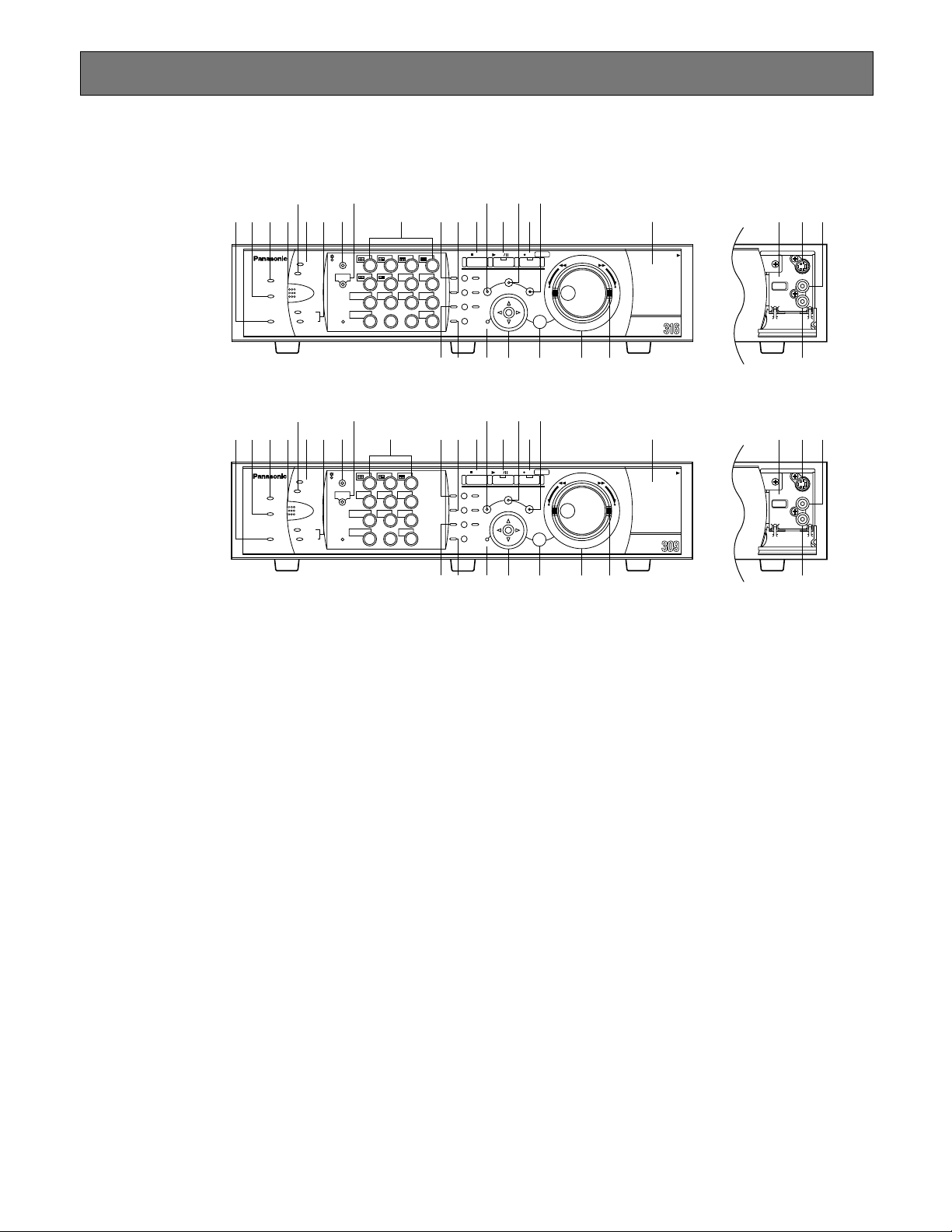
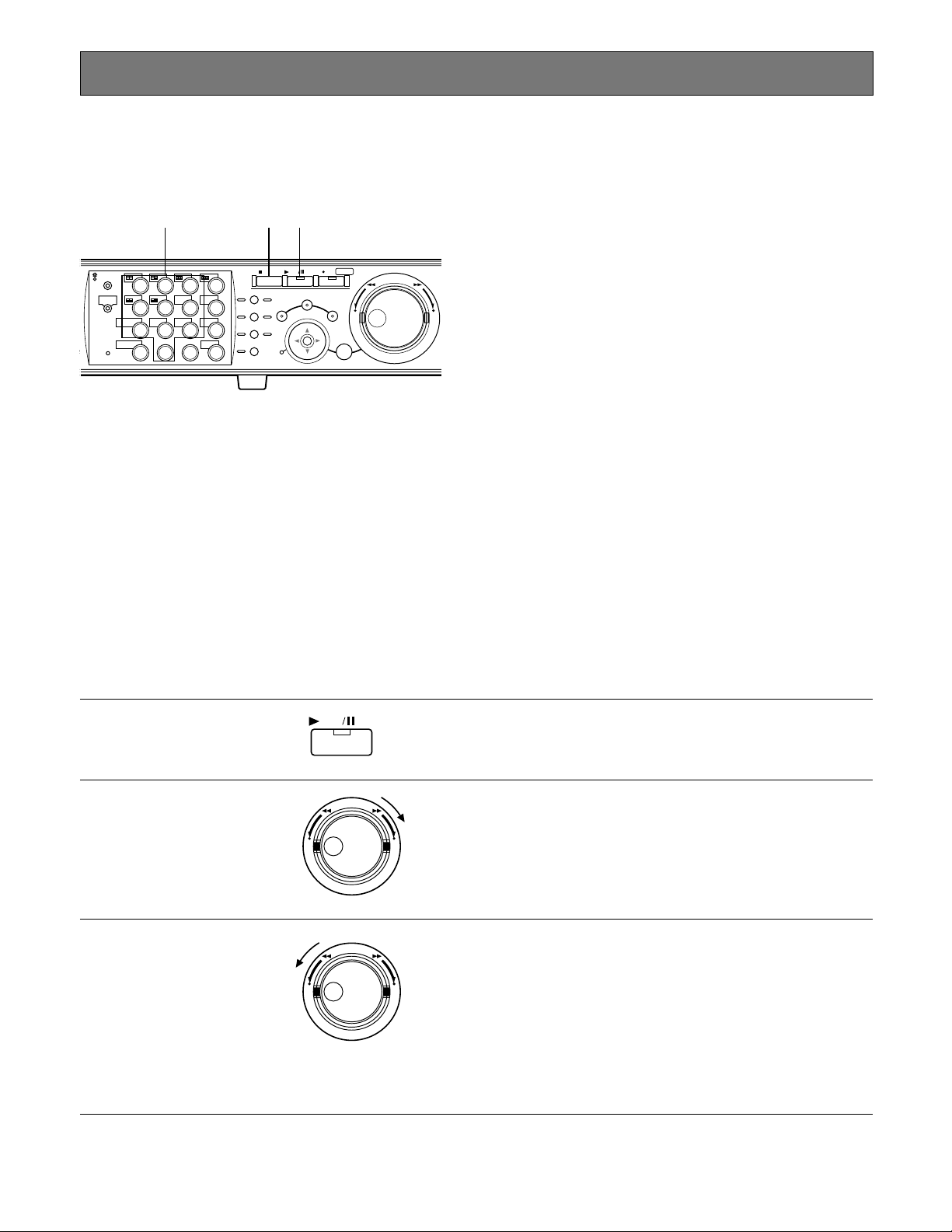
■ On the Monitor 1 (To display
only live image)
1. Camera Title
Displays the edited camera title.
A position to display a camera title can be selected
from the following.
Upper left, upper right, lower left, lower right, center
The default camera title position is lower right (RLOWER).
2. Time
Displays the current time (hour:minute:second) and
date (year:month:day).
A position to display the time can be selected from the
following.
Center, upper left, lower left, upper right, lower right
The default time display position is lower left (LLOWER).
Note: When the camera title and the time display are
layered in a multi-screen display, only the time display will be displayed.
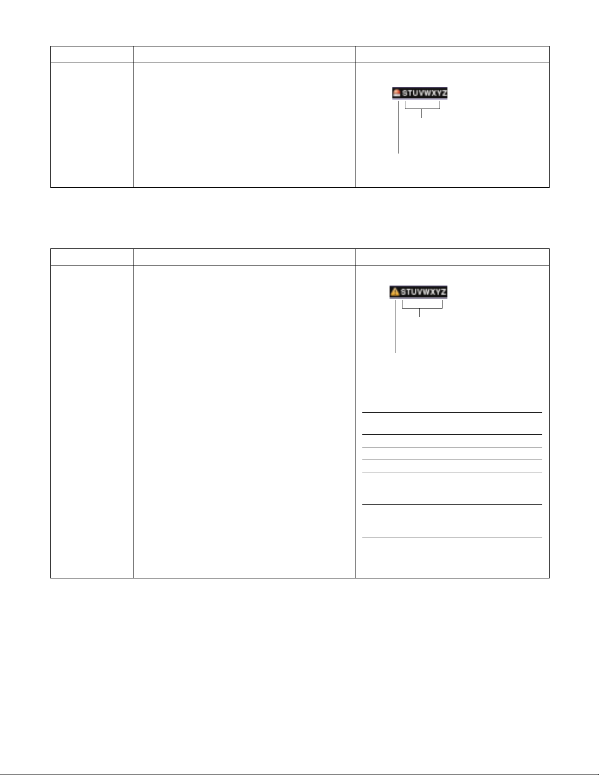
3. Alarm Display
When an alarm occurred, an alarm display will be displayed.
The alarm display will be displayed differently as follows depending on which alarm has occurred.
VMD-*: When motion is detected.
LOSS-*: When video loss occurred.
COM-#: When a command alarm occurred.
TRM-#: When a terminal alarm occurred.
*: Camera number (1 - 16 for WJ-HD316, 1 - 9 for WJ-
HD309)
#: Event number
Note: Refer to page XX for further information about
event types and event actions.
q
q
q
q
wewe
q
wewe
Page 12
12
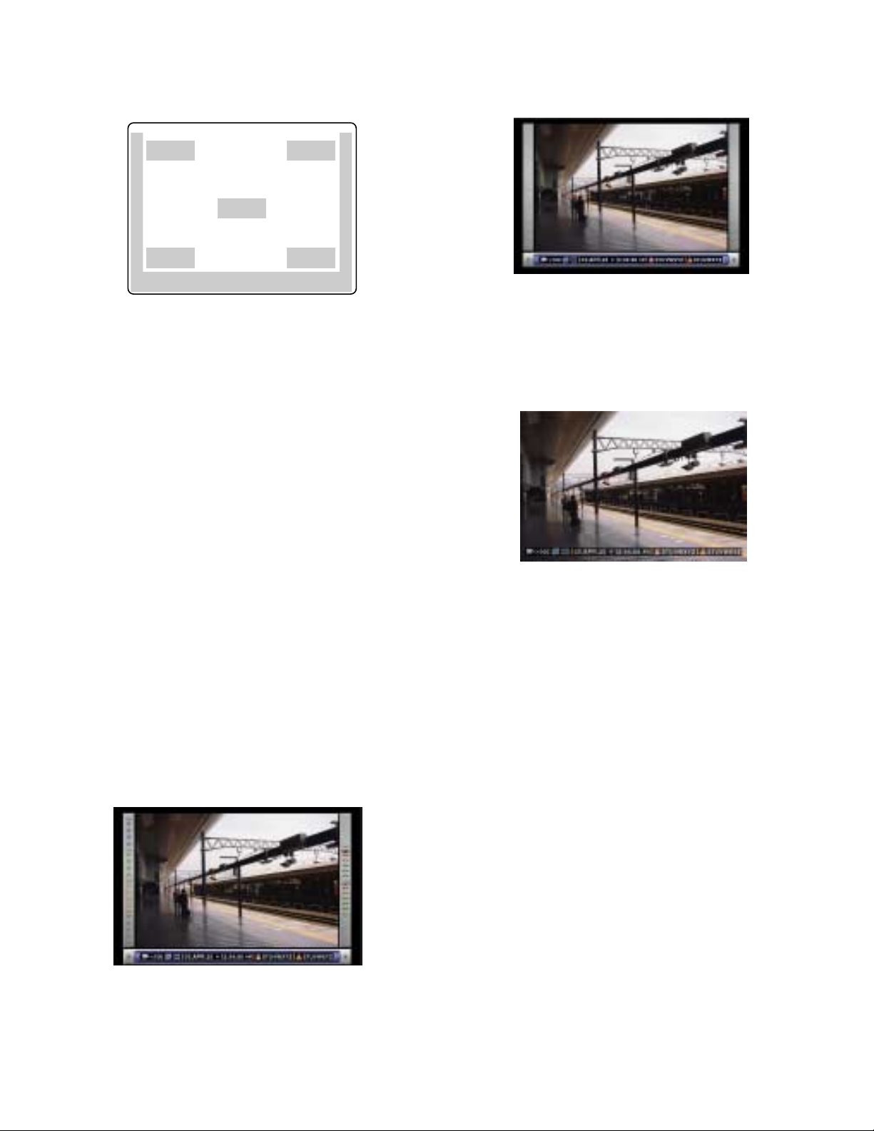
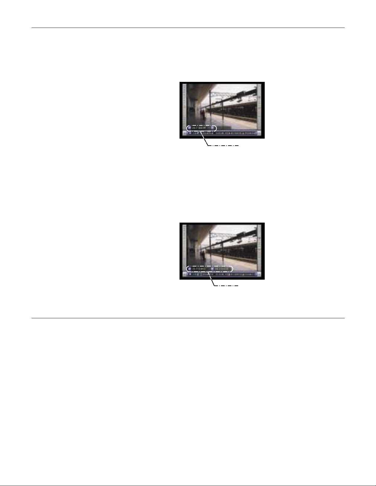
■ On the Monitor 2 (To display live
or recorded image)
Note: The same image will be displayed on the monitor 2
and the VGA monitor.
Important
Since VGA output from this unit is the same as for televisions (720 H x 480 V pixels/vertical frequency of 59.94 Hz),
it may be possible that both the left and right edges can not
be fit in the screen depending on a VGA monitor.
1. Camera Title
Displays the edited camera title.
A position to display a camera title can be selected
from the following.
Upper left, upper right, lower left, lower right, center
The default camera title position is lower right (RLOWER).
2. Task Bar
Displays the current statuses.
The task bar consists of the main bar (w - A), the left
bar (w - B), and the right bar (w - C).
There are 3 different ways to display the task bar as follows.
Style1
Displays only the main bar and the statuses is displayed on it.
Style2
Displays the statuses on all of the main bar, the left bar
and the right bar.
Style3
Displays the statuses only on the main bar, and not display information on the left bar and the right bar.
Note: Style2 and Style3 are graphic images. They may
be displayed not so clear as style1.
q
w
–
C
q
w
B
q
–
q
q
w – A
Page 13
Delete
Search Indicates that searching is being performed currently
: Searching currently
13
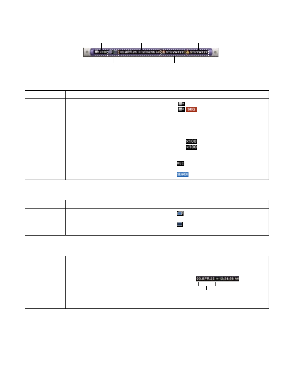
● Statuses on the Task Bar
• On the Main Bar
q Status Display Area
w Copy/Delete Icons
e Live/Playback Time Display Area
r Alarm Display Area
t Error Display Area
Recording
Indicated Item Status Indication
q Status Display Area
Live
Playback
Indicates live image display status
Indicates that playback is being performed currently
with displayed playback speed
: Live image is displayed
: Live images are displayed
sequentially
5: Playing currently
4: Playing reversely currently
h: Pausing currently
2 : Playing at fast speed currently
1 : Playing reversely at fast speed
currently
Indicates that recording is being performed currently
: Recording currently
: Deleting data currently
Indicated Item Status Indication
Copy Indicates that data copy is being performed currently
: Copying currently
Indicates that data deletion is being peformed currently
w Copy/Delete Icons
Indicated Item Status Indication
Time Displays time of the displayed image
When displaying live image: Current time
When playing recorded image: Time when
recorded
*: During the summer time, an asterisk (*) will be
displayed on the left side of the displayed time.
e Live/Playback Time Display Area
Year:Month:Day Hour:Minute:Second
Page 14
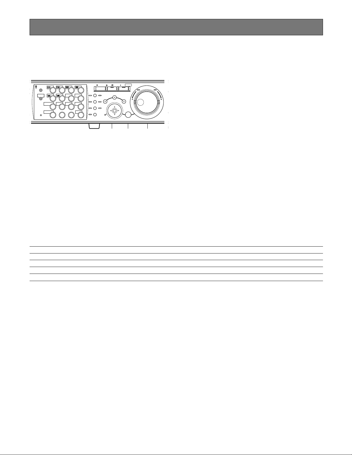
t Error Display Area
Indicated Item Status Indication
Error Warning Indicates an error occurrence or warning
ALT-*: Alteration is detected
R-ERROR: Failed to read data from the HDD
W-ERROR: Failed to write data on the HDD
SMART: Warning of the HDD malfunction
H-METER: Set time for hour-meter (active time of
the HDD) warning has passed
THERMAL: The temperature inside the unit is too
high
POWER:The power outage is detected
#-nn%: Warning about running out of disk space
with displaying available disk space percentage
#-FULL: No available disk space
MEDIUM-n: An error occurred in an external
recording device
REMOVE: The hard disk is removed from the sys-
tem automatically because of an access error
FAN: The fan is faulty
*: Camera number (1 - 16 for WJ-HD316, 1 - 9 for
WJ-HD309)
#: Abbreviation that indicates partition
nn: Available disk size
n: Number of connector an external recording
device is connected
Abbreviation of partition
Status Displayed
abbreviation
Normal recording area NML
Event recording area EVT
Copy area CPY
External recording device
connected to the COPY1 port
on the rear panel CP1
External recording device
connected to the COPY2 port
on the front panel CP2
Note: Refer to page XX for further information about error types and what to do when error occurred.
Error type
Error is occurring currently
14
r Alarm Display Area
Indicated Item Status Indication
Alarm Indicates that an alarm has occurred
VMD-*: When motion is detected
LOSS-*: When video loss occurred
COM-*: When a command alarm occurred
TRM-*: When a terminal alarm occurred
*: Camera number (1 - 16 for WJ-HD316, 1 - 9 for WJ-
HD309)
#: Alarm number
Note: Refer to page XX for further information about alarm types and alarm operations.
Alarm type
Alarm is occurring currently
Page 15

Indicates that available disk space of each partition.
Top: 100% of the disk space is used (no avail-
able disk space)
Second from the top: 80% of the disk space is
used
Center: 60% of the disk space is used
Second from the bottom: 40% of the disk space
is used
Bottom: 20% of the disk space is used
Note: When "CONTINUE" is selected on the
"Termination" page of the "Maintenance" setup
menu, available disk space will not be displayed.
Refer to a system administrator for further information.
NML: Available disk space of normal recording
area used for manual recording and scheduled recording
EVT: Available disk space of event recording
area used for event recording and emergency
recording
15
Indicated Item
Camera Indicates recording and displaying status
Gray: Camera currently not displayed or not con-
nected to a respective channel
Green: Camera displayed on the monitor
Orange: Camera currently being recorded
Blue: Camera currently being recorded and dis-
played on the monitor
Status Indication
• On the Right Bar
Indicated Item
Used disk space
Status Indication
• On the Left Bar
Event Recording Area
Normal Recording Area
Camera 1 is on the top and camera
16 is on the bottom
Page 16

16
z Insert the power plug to an outlet
(AC 120 V, 60 Hz)
Note: Make sure the power source is AC 120 V, 60 Hz.
x Turn the power switch on the rear
panel on.
The OPERATE indicator will light and the system check
(checking the system and hard disk) will start.
The startup splash image below will be displayed on the
monitor 2 and the VGA monitor during the system check.
When the auto login is off, the login window will be displayed if any button on the front panel of this unit is pressed
after the system check. (Go to step 3)
When the auto login is on, live image will be displayed after
the system check.
Notes:
• If the hard disk configuration had been changed after
the last startup or the hard disk has problems, the disk
configuration menu page will be displayed automatically after the startup splash. (Refer to page XX for further
information.)
• It is possible to display the disk configuration menu by
pressing the SET button when the image below that
says the system check has been completed is displayed.
Important
When using the optional extension unit (WJ-HDE300), turn
the power of this unit after turning on the power of all extension units.
c Enter a user name and password.
Rotate the jog dial to select a character to be entered in the
cursor position.
It is also possible to enter numbers by pressing the camera
selection buttons ([1] - [10/0] for WJ-HD316, [1] - [9], [0] for
WJ-HD309).
To move the cursor, press the arrow buttons.
It is the same way to enter characters as the way to edit
characters attached to images. Refer to page XX for further
information.
v Display live image.
Press the SET button to display live image.
If the authentication window is displayed, enter user name
and password.
When authenticated, live image will be displayed.
When not authenticated, the authentication window will be
displayed again.
STARTUP
Page 17

17
CLOCK ADJUSTMENT
It is recommended to check the clock periodically and put
the clock right if it shows the wrong time.
Adjust the clock when displaying live image.
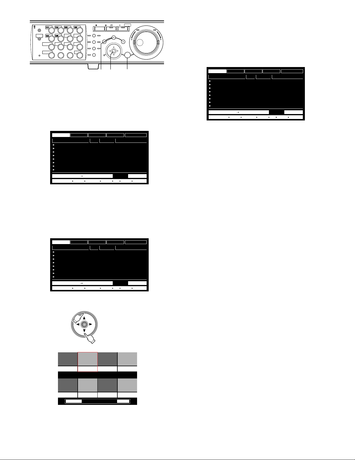
z Press the SETUP/ESC button for 2
seconds or more.
The SETUP MENU will be displayed on the monitor 2 and
the VGA monitor.
x Move the cursor to "System" using
the arrows button (DCAB) and
press the SET button.
c Move the cursor to "Time & Date"
using the arrows button (C D).
The "Time & Date" menu will be displayed.
v Press the SET button.
b Move the cursor to "Time Format"
using the arrows button and set the
time (Month, Day, Year, Time) using
the jog dial.
n Move the cursor to "SET" and press
the SET button.
The selected date format and the set time will be applied.
m Press the SETUP/ESC button for 2
seconds or more.
The SETUP MENU will disappear and live image will be displayed.
316
zm
STOP
PLAY PAUSE
REC
-
SEARCH
SETUP
/ESC
REC STOP
SET
REV FWD
–
+
MONITOR1
MONITOR2
SHIFT SEQ
DISK SELECT
EL-ZOOM
2
1
5
6
COPY
9
10/0
1413
TEXT
LOGOUT
3
4
OSD
7
8
MARK
12
11
LOGOUT
15
16
PAN /T ILT
ZOOM/
FOCUS
IRIS
PRESET
/AUTO
GOTO
LAST
A-B
REPEAT
LISTED
PAN/TILT
SLOW
BUSY
vn bxcb
SET UP MENU
REC Rate Status
Disk Info.
Version Info.
Disk End Mode
Disk Capacity
Date Delete
Maintenance
Event Log
Error Log
Access Log
Recording Event Schedule
Maintenance
Display ComSwitcher
MANU SCHE
CAM 1
AUTO
CAM 2
AUTO
CAM 3
AUTO
CAM 4
AUTO
CAM 5
AUTO
CAM 6
AUTO
CAM 7
AUTO
CAM 8
AUTO
CAM 9
AUTO
CAM 10
AUTO
CAM 11
AUTO
CAM 12
AUTO
CAM 13
AUTO
CAM 14
AUTO
CAM 15
AUTO
CAM 16
AUTO
LIVE
System
POST EVT
EMR
PRE EVT
1ips
1ips
1ips
1ips
1ips
1ips
1ips
1ips
1ips
1ips
1ips
1ips
1ips
1ips
1ips
1ips
1ips
1ips
1ips
1ips
1ips
1ips
1ips
1ips
1ips
1ips
1ips
1ips
1ips
1ips
1ips
1ips
1ips
1ips
1ips
1ips
1ips
1ips
1ips
1ips
1ips
1ips
1ips
1ips
1ips
1ips
1ips
1ips
1ips
1ips
1ips
1ips
1ips
1ips
1ips
1ips
SUPER FINE
1ips
1ips
FINE
1ips
1ips
NORMAL
1ips
1ips
EXTENDED
1ips
1ips
SETUP MENU
Basic Setup
Time & Date
User Regist.
User Edit
User Delete
Host Regist.
Host Edit
Host Delete
User Level
Save/Load
Maintenance Recording Event
Switcher
Display
User Setup Save
■
User Setup Load
■
Schedule
LIVE
System
Com
SAVE
Load
SETUPMENU
基本設定
日付時刻設定
ユーザー登録
ユーザー修正
ユーザー削除
ホスト登録
ホスト修正
ホスト削除
レベル設定
セーブ・ロード
録画
メンテナンス
スイッチャ
表示
■日付表示形式
■時刻表示形式
JUN
01 03 10 10 10
■自動時刻合わせ
・MASTER動作時刻
■サマータイム
■サマータイム切り替え設定
イベント動作
通信
スケジュール
システム
MMM/DD/YY
OFF
::
MASTER
10 :00
AUTO
LIVE
適用
設定へ
SETUP MENU
Basic Setup
Time & Date Setup
User Regist.
User Edit
User Delete
Host Regist.
Host Edit
Host Delete
User Level
Save/Load
Maintenance Recording Event
Switcher
Display
Host IP Address
■
Schedule
LIVE
System
Com
0. 0. 0. 0
DELETE
Page 18

18
SHUTDOWN
To shutdown the unit, do the followings.
1. In case recording is being performed, press the REC
button for 2 or more seconds. Recording will stop and
the indicator on the REC button will go off.
2. In case playback is being performed, press the STOP
button. Playback will stop and the indicator on the
PLAY/PAUSE button will go off.
3. Turn the power of the unit off using the POWER switch
on the rear panel. The OPERATE indicator will go off.
Important
• Detach the plug from the outlet if not operating the unit
for a length of time.
• In case the unit has not been operated for a certain
period, turn on the power of the unit between whiles to
prevent interference with functions.
Page 19
19
When recording with higher priority than manual recording
is performed, manual recording will not be performed until
this recording finishes.
Refer to the following about the recording mode.
x Stop recording.
Press the REC button down for around 2 seconds.
The indicator on the button will go off and recording will
stop.
Notes:
• A camera selection button will light orange (currently
being recording) or blue (currently being recorded and
displayed on the monitor) to indicate which camera is
being recorded.
• When recording with other recording mode is being
performed, the indicator on the REC button will not go
off even though the REC button is pressed to stop manual recording.
Do the followings to recordmanually.
Refer to a system administrator about the required settings
for manual recording.
z Start recording.
Press the REC button to start recording.
The indicator on the button will light and recording will start.
Images from all the connected cameras will be recorded
with the default setting.
It is possible to record only images displayed on the monitor 2 and the VGA monitor by changing the setting.
2
316
RECORDING (Manual Recording)
● Recording Mode and Priority
There are 4 recording modes as follows.
Recording Mode Description Priority*1
Emergency Recording Start recording manually using an external switch at an emergency event occurrence 1
Event Recording Recording will be performed automatically at an event occurrence 2
*2
Manual Recording Start and stop recording manually 3
*2
Scheduled Recording Recording will be performed with a designated start/stop time and date automatically 4
*2
*1: Priorities on the above table are the default settings. (Emergency recording is the highest priority.)
*2: Priorities for manual recording, scheduled recording and event recording can be changed. Refer to a system administrator
about the settings.
STOP
PLAY PAUSE
REC
-
SEARCH
SETUP
/ESC
REC STOP
SET
–
REV FWD
+
MONITOR1
MONITOR2
SHIFT SEQ
DISK SELECT
EL-ZOOM
2
1
5
6
COPY
9
10/0
1413
TEXT
LOGOUT
3
4
OSD
7
8
MARK
12
11
LOGOUT
15
16
PAN /T ILT
ZOOM/
FOCUS
IRIS
PRESET
/AUTO
GOTO
LAST
A-B
REPEAT
LISTED
PAN/TILT
SLOW
BUSY
c cv
Page 20

20
● Recording Time
Approximate possible recording durations will be as follows (with built-in HDD, manual recording):
Recording with audio
Unit: Hour
EXA NQA FQA SFA
Recording Rate (For Long Time Recording) (Standard) (High Quality) (Highest Quality)
2 2 040 1 730 1 320 1 070
3 2 040 1 730 1 320 1 070
5 680 570 440 1 070
6 1 270 950 630 470
7.5 680 570 440 350
10 510 430 330 260
15 400 340 260 210
30 200 170 130 100
60 60 50 40 30
Recording without audio
Unit: Hour
EXA NQA FQA SFA
Recording Rate (For Long Time Recording) (Standard) (High Quality) (Highest Quality)
2 3 810 2 860 1 900 1 430
3 3 810 2 860 1 900 1 430
5 1 270 950 630 470
6 1 270 950 630 470
7.5 950 710 470 350
10 760 570 380 280
15 760 570 380 280
30 380 280 190 140
60 120 90 60 40
Important
The possible recording durations on the above tables are approximate durations under the conditions below. Refer to a system
administrator for further information.
• Recording on the built-in hard disk (160 GB x 2)
• Recording all camera channels by manual recording
• "AUTO" is selected for the recording rate
Page 21

21
Record manually using an external switch at an emergency
event occurrence.
For example, install an external switch at the reception
counter, and start recording using it when a suspicious
individual appears.
Refer to a system administrator about the required settings
for emergency recording.
z Press the external switch.
The indicator on the REC button will light and recording will
start.
With the default setting, recording will be performed for 10
seconds.
Emergency recording is the highest priority. Emergency
recording will be performed even when this unit is recording in other recording mode.
x Stop recording.
When recording duration set in advance had passed,
recording will stop automatically.
With the default setting, recording will be stop automatically
after recording for 10 seconds.
When "CONTINUE" is selected for "Recording Time" of
"Emergency REC" on the SETUP MENU (Recording), press
the ALARM RESET button to stop recording.
The indicator on the REC button will go off and recording
will stop.
Important
• A camera selection button will light orange (currently
being recording) or blue (currently being recorded and
displayed on the monitor) to indicate which camera is
being recorded.
• When starting emergency recording during other
recording with different recording mode is being performed, the indicator on the REC button will keep on
being lit and other recording will be resumed after the
emergency recording finished.
● Recording duration of emergency
recording
Recording duration of emergency recording can be set as
follows. Refer to a system administrator for further information.
Parameter Recording Duration
1 s - 10 s Record for the selected time (1 - 10 sec-
onds , can be set in 1 second step)
20 s Record for 20 seconds
30 s Record for 30 seconds
1 m - 10 m Record for the selected time (1 -10 min-
utes can be set in 1 minute step)
20 m - 60 m Record for the selected time (20 - 60 min-
utes, can be set in 10 minutes step)
MANUAL Record only while the external switch is
being pressed down
CONTINUE Record until the ALARM RESET button is
pressed
RECORDING (Emergency Recording)
2
316
z
x
STOP
PLAY PAUSE
REC
-
SEARCH
SETUP
/ESC
REC STOP
SET
–
REV FWD
+
MONITOR1
MONITOR2
SHIFT SEQ
DISK SELECT
EL-ZOOM
2
1
5
6
COPY
9
10/0
1413
TEXT
LOGOUT
3
4
OSD
7
8
MARK
12
11
LOGOUT
16
15
PAN /T ILT
ZOOM/
FOCUS
IRIS
PRESET
/AUTO
GOTO
LAST
A-B
REPEAT
LISTED
PAN/TILT
SLOW
BUSY
Page 22
22
It is possible to play recorded image without stopping
recording.
Playback image will be displayed on the monitor 2 and the
VGA monitor.
z Select a camera respective to
recorded images to be played. (Go to
step 2 if not necessary)
Press a desired camera selection button.
The pressed camera selection button will light green and
respective live image will be displayed.
x Start playback.
Press the PLAY/PAUSE button.
The indicator on the PLAY/PAUSE button will light and
recorded image of the selected camera will be played.
First playback after login: The latest recorded image will
be played.
With the default setting, playback will start 5 seconds
before the start time of the latest recorded image. Start
time can be selected from the following:
5 s before/10 s before/30 s before/1 m before/5 m
before
Refer to a system administrator about the settings.
Other than those above: Playback will start from the end
point of the recorded image played last time.
c Stop playback.
Press the STOP button.
The indicator on the PLAY/PAUSE button will go off and
playback will be stopped.
Live image will be displayed on the monitor 2 and the VGA
monitor.
PLAYBACK
316
● Available functions during playback
Pause Pressing the PLAY/PAUSE button to pause playback. While pausing,
the indicator on the PLAY/PAUSE button will blink.
Pressing this button again will resume playback.
Single frame skip Rotating the jog dial during pause will skip to the next or previous
frame.
Rotating the jog dial clockwise will skip to the next frame and rotating
it counterclockwise will skip to the previous frame.
Fast forward/Fast reverse Rotating the shuttle ring will change the playback speed (1/2x, 1x, 2x,
5x, 10x, 20x) according to rotated degree. When the shuttle ring is
held in the 20x position (rotated to the end) for 10 seconds, the playback speed will be 50x. When the shuttle ring is held 5 more seconds
after the playback speed became 50x, the playback speed will be
100x.
Rotating the shuttle ring clockwise will play at fast speed and rotating
it counterclockwise will play reversely at fast speed.
To play at normal speed, release the shuttle ring.
c
STOP
GOTO
LAST
REPEAT
LISTED
x
PLAY PAUSE
REC
-
REC STOP
SEARCH
PAN/TILT
SLOW
A-B
BUSY
SETUP
/ESC
REV FWD
–
SET
+
z
MONITOR1
MONITOR2
SHIFT SEQ
DISK SELECT
EL-ZOOM
2
1
5
6
COPY
9
10/0
1413
TEXT
LOGOUT
3
4
PAN /T ILT
OSD
MARK
LOGOUT
ZOOM/
8
FOCUS
IRIS
12
PRESET
/AUTO
16
7
11
15
PLAY PAUSE
REV
FWD
– +
REV
FWD
– +
Page 23

23
Hold playback speed Press the SET button while holding the rotated shuttle ring to hold a
desired playback speed. (Playback speed will be held even though
the shuttle ring is released.)
To return to the normal playback speed, press the SET button.
Skip Rotating the jog dial during playback will skip to the next or previous
recorded image.
Rotating the jog dial clockwise will skip to the next recorded image
and rotating it counterclockwise will skip to the previous one.
If there is no next or previous recorded image, current playback will
be continued.
Play the latest recorded image Press the GO TO LAST button to play the latest recorded image.
Multi-screen display It is possible to display recorded images in multi-screen
(4/7/9/10/13/16 for WJ-HD316, 4/7/9 for WJ-HD306).
q Press the SHIFT button. The SHIFT indicator will light.
w Press a camera selection button (1 - 6 for WJ-HD316, 1 - 3 for WJ-
HD306) to select a desired multi-screen.
Camera selection button 1: 4 split screen
Camera selection button 2: 7 split screen
Camera selection button 3: 9 split screen
Camera selection button 4: 16 split screen (Only for WJ-HD316)
Camera selection button 5: 10 split screen (Only for WJ-HD316)
Camera selection button 6: 13 split screen (Only for WJ-HD316)
e To display recorded image on a single screen, press the SHIFT
button again.
After the SHIFT indicator went off, press a camera selection button.
Marking It is possible to play from a marked point. Do the followings to mark a
desired point.
1. Press the SHIFT button. The SHIFT indicator will light.
2. Press the camera selection button 12 (9 for WJ-HD309) (MARK) at
a desired point to be marked during playback.
Up to 100 points can be marked.
When marked while displaying multi-screen, same number of split
screen will be counted as marked point. (When a point is marked
while displaying 16 split screen, 16 points will be marked simultaneously.)
Text display It is possible to display text information attached to recorded image
while playback.
Text display is available only when playing on a single screen.
q Pause playback.
w Press the SHIFT button. The SHIFT indicator will light.
e Press the camera selection button 11 (5 for WJ-HD309) (TEXT).
+
REV
FWD
– +
SET
Page 24
A - B repeat playback It is possible to play recorded images between two designated points
repeatedly.
q Designate a start point (A) by pressing the A - B REPEAT button
during playback.
The A - B REPEAT indicator will start blinking, and the time of point
A will be displayed.
To cancel the designated point, press the SETUP/ESC button.
w Designate an end point (B) by pressing the A - B REPEAT button
during playback.
Playback between point A and B will start and keep on playing
repeatedly.
The time of point A and B will be displayed during playback.
e Press the A - B REPEAT button during A - B repeat playback to
return to normal playback.
24
Time of point A
Time of point A and B
Page 25
25
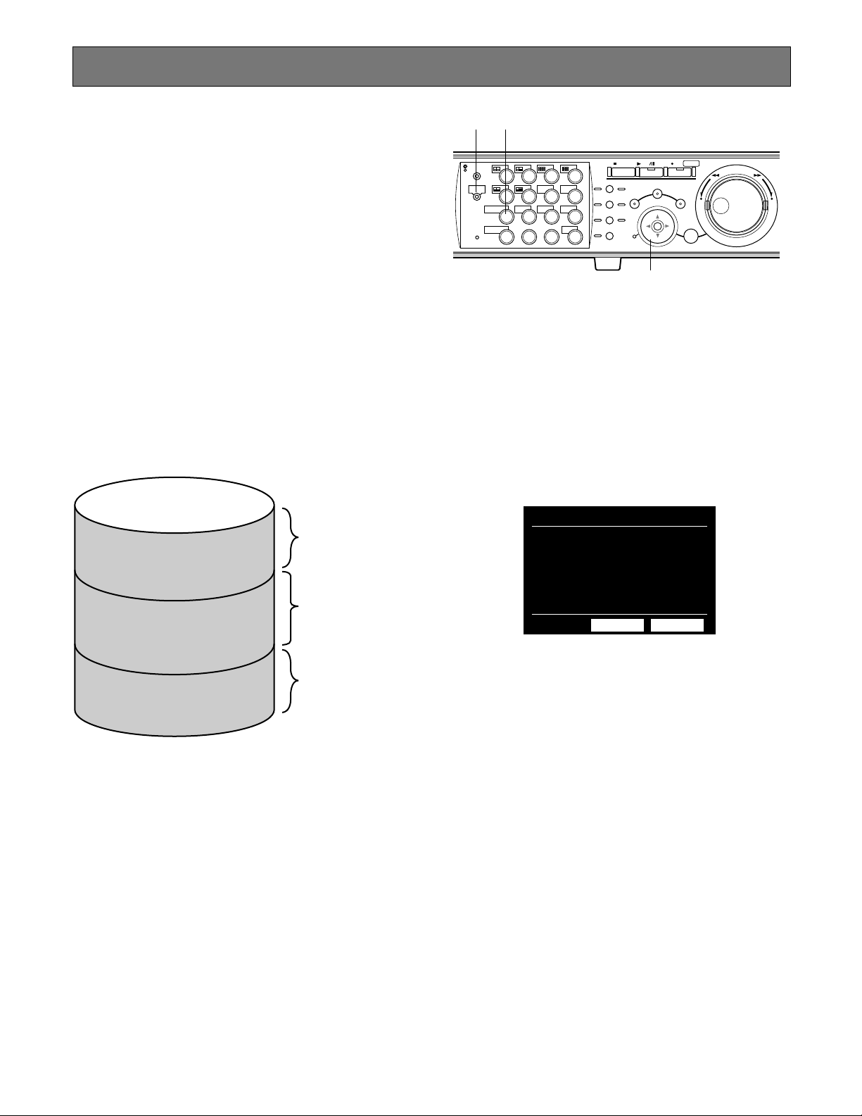
Images from a camera will be recorded on the built-in hard
disk or external recording devices (DVD-RAM drive, DVD-R
drive or CD-R drive) connected with this unit.
Available disk space or disks are as follows.
Note: External recording devices can be used as copy
area of images recorded on the hard disk. It is impossible to record images on the external recording devices
directly.
HDD Normal Recording Area/Event Recording Area:
Disk space for recording on the built-in hard disk
Recorded image by manual recording (refer to page
XX) or event recording (refer to page XX) will be stored
in this area.
HDD Copy Area: Disk space for recording on the built-in
hard disk
Recorded images willbe copied in this area (refer to
page XX).
Notes:
• Playback image will be displayed only on the monitor 2
and the VGA monitor.
• Playback can be performed during recording.
• Disk space size of each recording area differs depending on the settings.
Refer to a system administrator for further information.
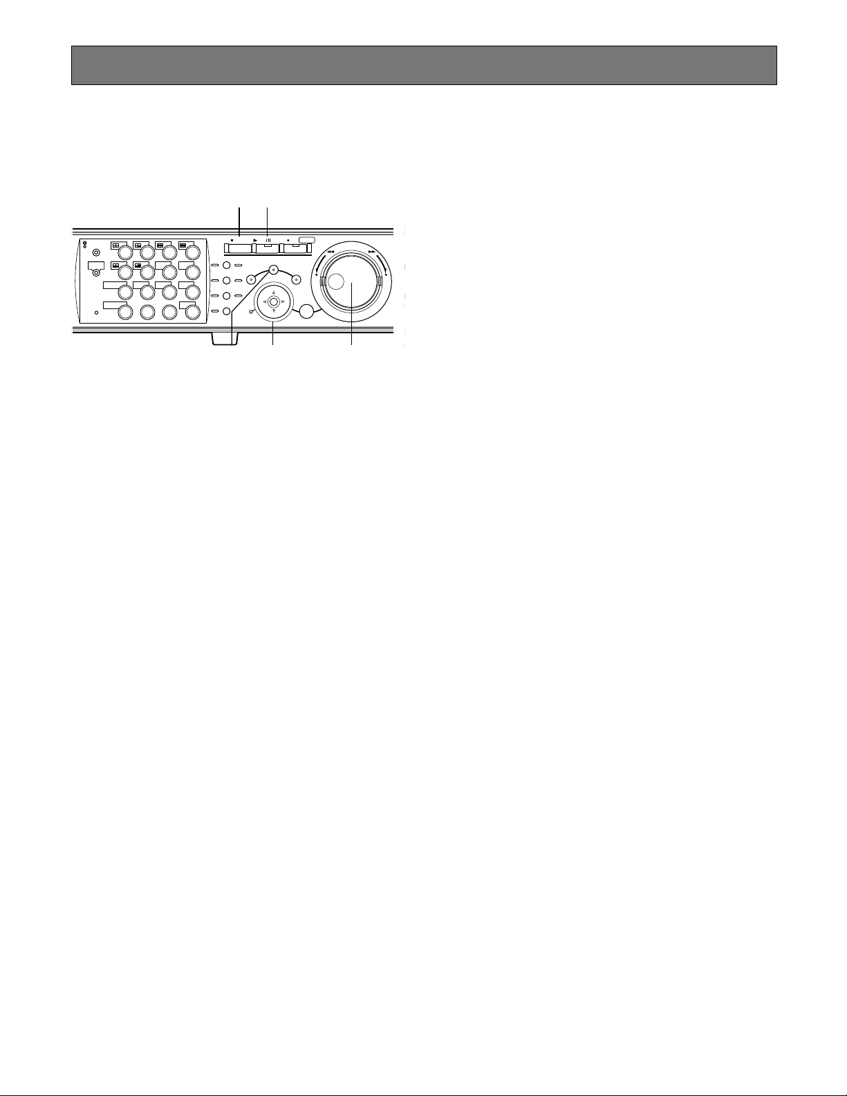
z Press the SHIFT button.
The SHIFT indicator will light.
x Press the camera selection button 9
(7 for WJ-HD309) (DISK SELECT).
The DISK SELECTION window will be displayed on the
monitor 2 and the VGA monitor.
c Move the cursor to select a disk to
be played using the arrow buttons
and rotate the jog dial to check the
radio button next to the selected
disk. Press the SET button to
determine the selection.
The COPY DATA window will be displayed when "HDD
Copy Area" is selected.
The RECORDING EVENT LIST window will be displayed
when "HDD Normal/Event Recording Area" is selected.
(Refer to page XX for further information.)
To close the DISK SELECTION window, move the cursor to
select "CANCEL" and press the SET button.
v Rotate the jog dial to select a desired
recorded image to be played, and
press the SET button to determine
the selection.
Playback Image on a Designated Disk
316
Built-in hard disk
Recording area for
manual recording and
normal schedule
Normal recording area
Event recording area
recording
Recording area for
event recording and
emergency recording
x
z
STOP
PLAY PAUSE
REC
-
SEARCH
SETUP
/ESC
REC STOP
SET
REV FWD
–
+
MONITOR1
MONITOR2
SHIFT SEQ
DISK SELECT
EL-ZOOM
2
1
5
6
COPY
9
10/0
1413
TEXT
LOGOUT
3
4
OSD
7
8
MARK
12
11
LOGOUT
15
16
PAN /T ILT
ZOOM/
FOCUS
IRIS
PRESET
/AUTO
GOTO
LAST
A-B
REPEAT
LISTED
PAN/TILT
SLOW
BUSY
c
ディスク選択
●HDD通常領域/イベント領域
●HDDコピー領域
●COPY1
●COPY2
OK
キャンセル
Recording area for
copying
Copy area
Page 26

26
b Press the PLAY/PAUSE button to
play the selected recorded image.
The indicator on the PLAY/P AUSE
button will light and the playback will
start.
n To stop playback, press the STOP
button. The indicator on the
PLAY/P AUSE button will go off and
the playback will stop.
Live image will be displayed on the monitor 2 and the VGA
monitor.
Notes:
• When "HDD Normal Recording Area/Event Recording
Area" is selected, pressing the PLAY/PAUSE button
after stopping playback will start playback from the end
point of the recorded image played last time.
• When "HDD Copy Area" is selected, pressing the
PLAY/PAUSE button after stopping playback will start
playback the latest image copied on the selected disk.
Page 27
27
It is possible to play recorded image from a designated
time and date without stopping recording.
Playback image will be displayed on the monitor 2 and the
VGA monitor.
z Press the SEARCH button
repeatedly until the time and date
designation window is displayed.
The time and date designation window will be displayed on
the monitor 2 and the VGA monitor.
x Enter the start time using the jog dial
and the arrows button.
Select time and date using the jog dial. To move the cursor,
use the arrows button (AB).
c Press the PLAY/PAUSE button.
The indicator on the PLAY/PAUSE button will light and start
playback from the entered time and date.
If there is no recorded image of the entered time:
When there are images recorded after the entered time, the
oldest recorded image after the entered time will be played.
When there is no image recorded after the entered time, the
newest recorded image before the entered time will be
played.
v Press the STOP button.
The indicator on the PLAY/PAUSE button will go off and
stop playback.
Live image will be displayed on the monitor 2 and the VGA
monitor.
316
Playback From a Designated Time and Date
v c
STOP
PLAY PAUSE
REC
-
SEARCH
SETUP
/ESC
REC STOP
SET
REV FWD
–
+
MONITOR1
MONITOR2
SHIFT SEQ
DISK SELECT
EL-ZOOM
2
1
5
6
COPY
9
10/0
1413
TEXT
LOGOUT
3
4
OSD
7
8
MARK
12
11
LOGOUT
15
16
PAN /T ILT
ZOOM/
FOCUS
IRIS
PRESET
/AUTO
GOTO
LAST
A-B
REPEAT
LISTED
PAN/TILT
SLOW
BUSY
x
xz
Page 28
28
There are 3 ways to search recorded image and play it.
• Search a recording event and play it (Recording event search)
• Search a motion detected time and date from recorded images and play it (VMD search)
• Search marked point and play it (Marking search)
Note: Playback image will be displayed on a single screen on the monitor 2 and the VGA monitor. To play in a multi-screen,
switch to a multi-screen after starting playback.
■ Searching Recording Event and Playback (Recording Event Search)
Display a list or a thumbnail of recording events, and select a desired recording event among them to play it.
It is possible to search using the following filters:
Searching Filters
TIME & DATE Search only images recorded in the entered time range.
CAMERA Search only recorded images from the selected camera channel.
REC EVENT Search only images recorded in the selected recording mode.
It is possible to search images recorded in the following recording mode:
EMERGENCY: Emergency recording (Refer to page XX.)
VMD: Event recording performed when motion had been detected (Refer to page XX.)
TERMINAL: Event recording performed when terminal alarm had been detected.
COMMAND: Event recording performed when command alarm had been detected.
VIDEO LOSS: Event recording performed when video loss had occurred.
MANUAL: Manual recording (Refer to page XX.)
SCHEDULE: Scheduled recording (Refer to page XX.)
TEXT Search only images recorded with text information
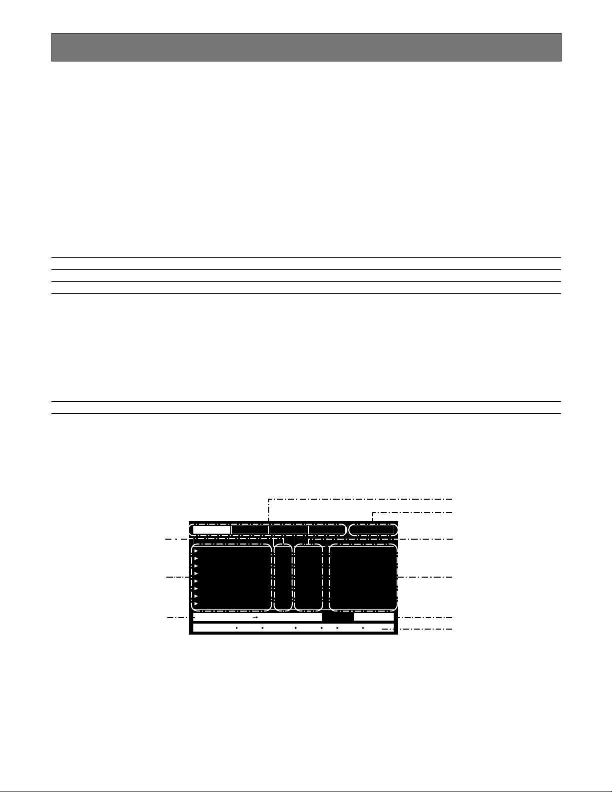
● Recording Event List Window
SEARCH AND PLAY
TIME&DATE
01ch
01ch
01ch
01ch
01ch
01ch
01ch
01ch
MANUAL
MANUAL
MANUAL
MANUAL
MANUAL
MANUAL
MANUAL
MANUAL
CAM REC EVT
ABCDEFGHIJKLMNOP
ABCDEFGHIJKLMNOP
ABCDEFGHIJKLMNOP
ABCDEFGHIJKLMNOP
ABCDEFGHIJKLMNOP
ABCDEFGHIJKLMNOP
ABCDEFGHIJKLMNOP
ABCDEFGHIJKLMNOP
TEXT
APR.25.03*12:34:56 AM
APR.25.03*12:34:56 AM
APR.25.03*12:34:56 AM
APR.25.03*12:34:56 AM
APR.25.03*12:34:56 AM
APR.25.03*12:34:56 AM
APR.25.03*12:34:56 AM
APR.25.03*12:34:56 AM
TIME&DATE SEARCH REC EVENT SEARCH VMD SEARCH MARK
TIME&DATE
CAMERA
REC EVENT
TEXT
UNLOCK FILTER
TOTALAPR.25.03*2:34:56 AM APR.25.03*12:34:56 AM 12345
Searching filter buttons
Filter cancel button
Recording event
Text information
Number of listed data
Searching information
Camera Channel
Time and date
Time range of listed data
Page 29
29
Searching filter buttons: Selects the searching filter
Filter cancel button: Cancels the selected searching filter and lists all recording events
Time and date: <When searched by recording event>
Time when recording started will be displayed.
<When searched by VMD>
Time when motion had been detected will be displayed.
<When searched by marked point>
Time when the point is marked will be displayed.
Camera channel: Camera channel of the recorded image will be displayed. The recorded image of the
displayed camera channel will be played on a single screen.
Recording event: Recording mode will be displayed.
Text information: First several characters of text information will be displayed if the image has text infor-
mation.
Time range of the listed data: Time range of the listed data will be displayed.
Number of the listed data: Number of the listed data will be displayed.
Searching information: Searching filter will be displayed. (A filter of currently displayed list will be displayed in
orange.)
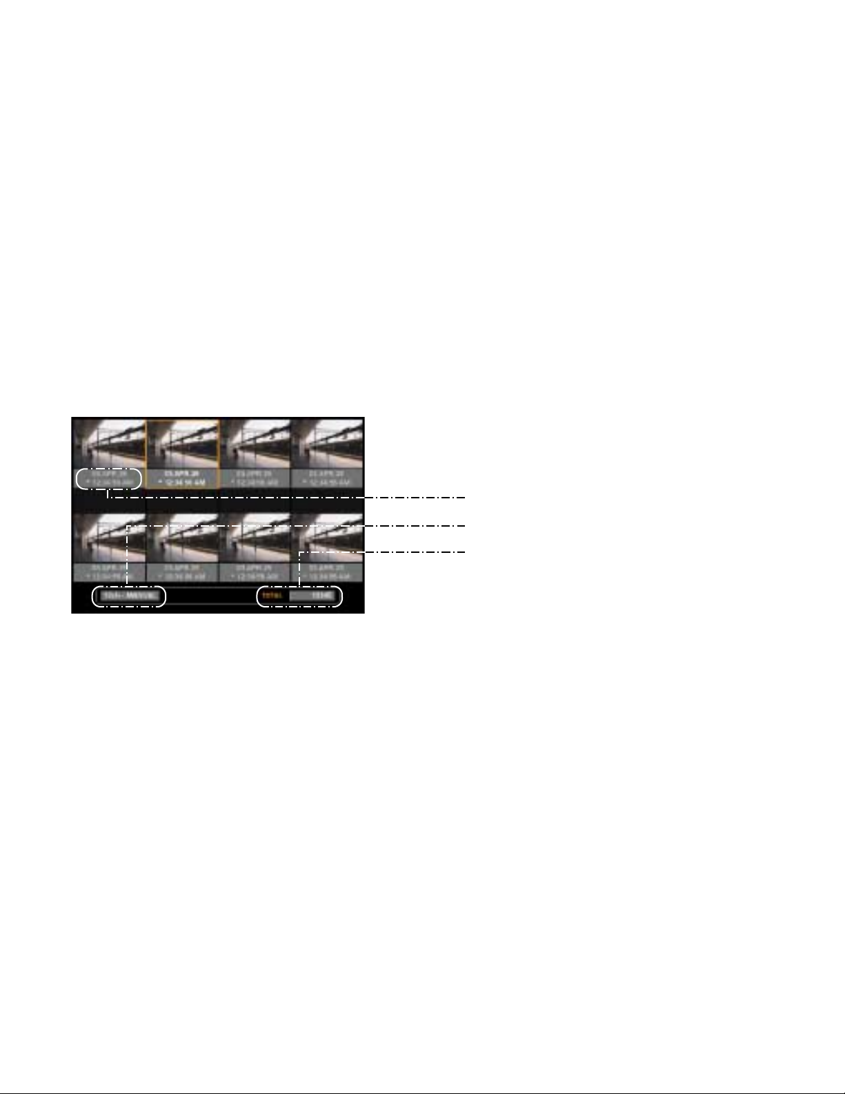
● Recording Event Thumbnail Window
Time and date
Camera channel/Recording event
Number of listed data
Time and date: <When searched by recording event>
Time when recording started will be displayed.
<When searched by VMD>
Time when motion had been detected will be displayed.
<When searched by marked point>
Time when the point is marked will be displayed.
Camera channel/Recording event: Camera channel of the recorded image will be displayed. The recorded image of the
displayed camera channel will be played on a single screen. Recording mode also will
be displayed.
Number of the listed data: Number of the listed data will be displayed.
Page 30
30
z Press the SEARCH button
repeatedly until the recording event
list window is displayed.
The recording event list window will be displayed on the
monitor 2 and the VGA monitor.
Use the arrows button (DC) to switch displaying the list
window and the thumbnail window alternately.
To search using a searching filter, go to step 4.
MONITOR1
316
⇔
x Use the arrows button (AB) to
select a searching filter (TIME &
DATE, CAMERA, EVENT, TEXT), and
press the SET button.
When a searching filter is selected, the respective searching filter window will be displayed.
Select "UNLOCK FILTER" and press the SET button to cancel the selected filter.
Refer to page XX about the searching filters.
<List window>
<Thumbnail window>
MONITOR2
SHIFT SEQ
DISK SELECT
EL-ZOOM
2
1
5
6
COPY
9
10/0
1413
TEXT
LOGOUT
STOP
PLAY PAUSE
REC
-
REC STOP
3
4
OSD
7
8
MARK
12
11
LOGOUT
15
16
PAN /T ILT
ZOOM/
FOCUS
IRIS
PRESET
/AUTO
GOTO
LAST
A-B
REPEAT
LISTED
SEARCH
PAN/TILT
SLOW
BUSY
SETUP
/ESC
REV FWD
–
SET
+
zz
x
x
TIME&DATE
APR.25.03*12:34:56 AM
APR.25.03*12:34:56 AM
APR.25.03*12:34:56 AM
APR.25.03*12:34:56 AM
APR.25.03*12:34:56 AM
APR.25.03*12:34:56 AM
APR.25.03*12:34:56 AM
APR.25.03*12:34:56 AM
CAMERA
TIME&DATE
TIME&DATE SEARCH REC EVENT SEARCH VMD SEARCH MARK
REC EVENT
CAM REC EVT
01ch
01ch
01ch
01ch
01ch
01ch
01ch
01ch
MANUAL
MANUAL
MANUAL
MANUAL
MANUAL
MANUAL
MANUAL
MANUAL
TEXT
UNLOCK FILTER
TEXT
ABCDEFGHIJKLMNOP
ABCDEFGHIJKLMNOP
ABCDEFGHIJKLMNOP
ABCDEFGHIJKLMNOP
ABCDEFGHIJKLMNOP
ABCDEFGHIJKLMNOP
ABCDEFGHIJKLMNOP
ABCDEFGHIJKLMNOP
TOTALAPR.25.03*2:34:56 AM APR.25.03*12:34:56 AM 12345
TIME&DATE
APR.25.03*12:34:56 AM
APR.25.03*12:34:56 AM
APR.25.03*12:34:56 AM
APR.25.03*12:34:56 AM
APR.25.03*12:34:56 AM
APR.25.03*12:34:56 AM
APR.25.03*12:34:56 AM
APR.25.03*12:34:56 AM
CAMERA
TIME&DATE
TIME&DATE SEARCH REC EVENT SEARCH VMD SEARCH MARK
REC EVENT
CAM REC EVT
01ch
01ch
01ch
01ch
01ch
01ch
01ch
01ch
MANUAL
MANUAL
MANUAL
MANUAL
MANUAL
MANUAL
MANUAL
MANUAL
TEXT
UNLOCK FILTER
TEXT
ABCDEFGHIJKLMNOP
ABCDEFGHIJKLMNOP
ABCDEFGHIJKLMNOP
ABCDEFGHIJKLMNOP
ABCDEFGHIJKLMNOP
ABCDEFGHIJKLMNOP
ABCDEFGHIJKLMNOP
ABCDEFGHIJKLMNOP
TOTALAPR.25.03*2:34:56 AM APR.25.03*12:34:56 AM 12345
03.APR.25
* 12:34:56 AM
03.APR.25
* 12:34:56 AM
03.APR.25
* 12:34:56 AM
03.APR.25
* 12:34:56 AM
03.APR.25
* 12:34:56 AM
03.APR.25
* 12:34:56 AM
03.APR.25
* 12:34:56 AM
03.APR.25
* 12:34:56 AM
12345TOTAL12ch. MANUAL
Page 31

31
MONITOR1
316
c Filter recording events.
Filter recording events by time and date
Move the cursor using the arrows button and rotate the jog
dial to enter time and date.
Press the SET button to determine the entered time and
date.
The recording event in the entered time range will be listed
and displayed.
Filter recording events by camera channel
Select camera channel numbers (1 - 16 for WJ-HD316, 1 9 for WJ-HD309) by pressing the camera selection buttons
to apply filtering.
The selected camera channels will be highlighted (white).
Press the SET button to determine the selection of camera
channel numbers.
The recording event of the selected camera channels will
be listed.
Filter recording events by recording event
Move the cursor to select the recording event (refer to page
xx) using the arrows button (DC) and rotate the jog dial to
ON.
Press the SET button to determine the selection.
The recording event of the selected filter will be listed.
Filter recording events by text information
Rotate the jog dial to select OFF, WITH TEXT or WITHOUT
TEXT.
Press the SET button to determine the selection.
The recording event filtered by the selected filter will be listed.
v Rotate the jog dial to select a
recording event to be played.
b Press the PLAY/PAUSE button.
The LISTED indicator and the indicator on the PLAY/PAUSE
button will light and playback of the selected recording
event will start.
Note: When the LISTED indicator is lit, only listed recording
events are available to be played. Press the LISTED
button during playback to make all recording events
available to be played.
n To stop playback, press the STOP
button.
The indicator on the PLAY/PAUSE button will go off and
playback will be stopped.
Live image will be displayed on the monitor 2 and the VGA
monitor.
MONITOR2
SHIFT SEQ
DISK SELECT
EL-ZOOM
2
1
5
6
COPY
9
10/0
1413
TEXT
LOGOUT
n
b
STOP
PLAY PAUSE
REC
-
REC STOP
3
4
OSD
7
8
MARK
12
11
LOGOUT
15
16
PAN /T ILT
ZOOM/
FOCUS
IRIS
PRESET
/AUTO
GOTO
LAST
REPEAT
LISTED
SEARCH
PAN/TILT
SLOW
A-B
BUSY
SETUP
/ESC
REV FWD
–
SET
+
cc
c
v
TIME&DATE FILTERING
■
START
YMD
2003 03 30
END
YMD
2003 05 20 5 03
SET : [SET] CANCEL : [ESC]
CAMERA FILTERING
CAMERA
1
2345
: PM
11 03
: AM
6 78
TEXT FILTERING
WITHOUT TEXT
SET : [ SET ] CANCEL : [ ESC ]
TIME&DATE
APR.25.03*12:34:56 AM
APR.25.03*12:34:56 AM
APR.25.03*12:34:56 AM
APR.25.03*12:34:56 AM
APR.25.03*12:34:56 AM
APR.25.03*12:34:56 AM
APR.25.03*12:34:56 AM
APR.25.03*12:34:56 AM
CAMERA
TIME&DATE
TIME&DATE SEARCH REC EVENT SEARCH VMD SEARCH MARK
REC EVENT
CAM REC EVT
01ch
01ch
01ch
01ch
01ch
01ch
01ch
01ch
MANUAL
MANUAL
MANUAL
MANUAL
MANUAL
MANUAL
MANUAL
MANUAL
TEXT
UNLOCK FILTER
TEXT
ABCDEFGHIJKLMNOP
ABCDEFGHIJKLMNOP
ABCDEFGHIJKLMNOP
ABCDEFGHIJKLMNOP
ABCDEFGHIJKLMNOP
ABCDEFGHIJKLMNOP
ABCDEFGHIJKLMNOP
ABCDEFGHIJKLMNOP
TOTALAPR.25.03*2:34:56 AM APR.25.03*12:34:56 AM 12345
9 10 11 12 13 14 15 16
SET : [ SET ] CANCEL : [ ESC ]
REC EVENT FILTERING
EMERGENCY
VMD
TERMINAL
COMMAND
VIDEO LOSS
MANUAL
SCHEDULE
SET : [ SET ] CANCEL : [ ESC ]
OFF
ON
ON
ON
ON
OFF
OFF
Page 32

32
■ Searching a motion detected
time and date from recorded
images and play it (VMD search)
Search a motion detected time and date from all images
recorded in all the recording modes, and display a list or a
thumbnail of the results.
Select a time and date displayed on the result list or thumbnail to play it.
It is possible to filter by camera channel, time and date,
detection area or searching mode, to list time and date of
events that recorded when motion had been detected.
z Press the SEARCH button
repeatedly until the VMD search list
is displayed.
The result list of the VMD search will be displayed on the
monitor 2 and the VGA monitor.
(The list in the displayed window is the results of the previous search.)
Use the arrows button (DC) to switch displaying the list
window and the thumbnail window alternately.
316
x Press the SET button.
The VMD search window will be displayed.
Enter a camera channel number and time range on the
VMD search window for the VMD search.
To search by the same conditions as the previous search,
press the PLAY/PAUSE button.
Go to the step 12 when the VMD search is performed and a
list of the results is displayed after the PLAY/PAUSE button
is pressed.
⇔
<List window>
<Thumbnail window>
VMD SEARCH
TIME&DATE
APR.25.03*12:34:56 AM
APR.25.03*12:34:56 AM
APR.25.03*12:34:56 AM
APR.25.03*12:34:56 AM
APR.25.03*12:34:56 AM
APR.25.03*12:34:56 AM
APR.25.03*12:34:56 AM
APR.25.03*12:34:56 AM
TIME&DATE SEARCH REC EVENT SEARCH VMD SEARCH MARK
CAM
01ch
01ch
01ch
01ch
01ch
01ch
01ch
01ch
TOTALAPR.25.03*2:34:56 AM APR.25.03*12:34:56 AM 12345
z
STOP
PLAY PAUSE
REC
-
SEARCH
SETUP
/ESC
REC STOP
SET
REV FWD
–
+
MONITOR1
MONITOR2
SHIFT SEQ
DISK SELECT
EL-ZOOM
2
1
5
6
COPY
9
10/0
1413
TEXT
LOGOUT
3
4
OSD
7
8
MARK
12
11
LOGOUT
15
16
PAN /T ILT
ZOOM/
FOCUS
IRIS
PRESET
/AUTO
GOTO
LAST
A-B
REPEAT
LISTED
PAN/TILT
SLOW
BUSY
x
VMD SEARCH
TIME&DATE
APR.25.03*12:34:56 AM
APR.25.03*12:34:56 AM
APR.25.03*12:34:56 AM
APR.25.03*12:34:56 AM
APR.25.03*12:34:56 AM
APR.25.03*12:34:56 AM
APR.25.03*12:34:56 AM
APR.25.03*12:34:56 AM
TIME&DATE SEARCH REC EVENT SEARCH VMD SEARCH MARK
CAM
01ch
01ch
01ch
01ch
01ch
01ch
01ch
01ch
TOTALAPR.25.03*2:34:56 AM APR.25.03*12:34:56 AM 12345
03.APR.25
* 12:34:56 AM
03.APR.25
* 12:34:56 AM
SELECT CAMERA & DATE
■
CAMERA
CAM1
START
2003
END
2003 05 20 5 03
03.APR.25
* 12:34:56 AM
03.APR.25
* 12:34:56 AM
03.APR.25
* 12:34:56 AM
03.APR.25
* 12:34:56 AM
03.APR.25
* 12:34:56 AM
03.APR.25
* 12:34:56 AM
12345TOTAL12ch. MANUAL
YMD : PM
03 30
YMD
SET : [SET] SEARCH : [PLAY] CANCEL : [ESC]
11 03
: AM
Page 33

33
c Move the cursor using the arrows
button and rotate the jog dial to
enter a camera channel number and
time range for the VMD search.
v Press the SET button.
The motion detection area setup window will be displayed.
To search by the same conditions as the previous search,
press the PLAY/PAUSE button.
Go to the step 12 when the VMD search is performed and a
list of the results is displayed after the PLAY/PAUSE button
is pressed.
b Rotate the jog dial to select "SETUP
AREA " on the status bar .
Note: It is possible to set all displayed area as motion
detection area by pressing the SET button after selecting "ALL AREA".
n Move the cross cursor using the
arrows button to a point to be
determined as the start point of
motion detection area.
Press the SET button to determine the selected point as the
start point of the motion detection area.
m Move the cross cursor using the
arrows button to a point to be
determined as the end point of the
motion detection area.
Press the SET button to determine the selected point as the
end point of the motion detection area.
It is possible to set up to 4 motion detection areas by
repeating step 6 and 7.
316
316
STOP
PLAY PAUSE
REC
-
SEARCH
c
SETUP
/ESC
REC STOP
SET
n
REV FWD
–
b
c
MONITOR1
MONITOR2
SHIFT SEQ
DISK SELECT
EL-ZOOM
2
1
5
6
COPY
9
10/0
1413
TEXT
LOGOUT
3
4
OSD
7
8
MARK
12
11
LOGOUT
15
16
PAN /T ILT
ZOOM/
FOCUS
IRIS
PRESET
/AUTO
GOTO
LAST
REPEAT
LISTED
PAN/TILT
SLOW
A-B
BUSY
n
SELECT CAMERA & DATE
■
CAMERA
CAM1
START
YMD : PM
2003
03 30
END
YMD
2003 05 20 5 03
SET : [SET] SEARCH : [PLAY] CANCEL : [ESC]
11 03
: AM
+
⁄1⁄3⁄4
STOP
PLAY PAUSE
REC
-
MONITOR1
MONITOR2
SHIFT SEQ
DISK SELECT
EL-ZOOM
2
1
5
6
COPY
9
10/0
1413
TEXT
LOGOUT
3
4
OSD
7
8
MARK
12
11
LOGOUT
15
16
PAN /T ILT
ZOOM/
FOCUS
IRIS
PRESET
/AUTO
GOTO
LAST
A-B
REPEAT
LISTED
PAN/TILT
SLOW
BUSY
m
⁄0
REC STOP
SEARCH
SETUP
/ESC
SET
⁄1 ,⁄0⁄2
m
REV FWD
–
.
+
Page 34

34
, Rotate the jog dial to select "EXIT"
on the status bar to exit from the
motion detection area setup window.
. Press the SET button to display the
VMD search window. Refer to page
xx for further information about each
of the detection mode.
⁄0 Move the cursor to select a detection
mode using the arrow buttons and
rotate the jog dial to check the radio
button next to the selected detection
mode. Press the SET button to
determine the selection.
Refer to page XX for further information about each of the
detection mode.
<ANY AREA mode>
Move the cursor to the parameter box using the arrows button [B] to select a masking duration from the following.
1S/1M/1H/24H
<VECTOR mode>
Move the cursor to an area for the settings of VECTOR
using the arrows button [B] and rotate the jog dial to select
an area. Move the cursor to the parameter box of the
selected area using the arrows button [B] to select an
interval time for an object moving between each area from
the following.
--/5 s/10 s/20 s/30 s/40 s/50 s/1 m
<DURATION>
Move the cursor to a parameter box of each area using the
arrows button [B] and rotate the jog dial to select a moving
duration for an object in each area from the following.
--/5 s/10 s/20 s/30 s/40 s/50 s/1 m
Refer to page 28 for further information about the detection
modes.
⁄1 Press the SET button or the
PLAY/P AUSE button to start
searching and display the result of
the VMD search.
⁄2 Rotate the jog dial to select a result
to be displayed.
⁄3 Press the PLAY/PAUSE button to
start playback.
The LISTED indicator and the indicator on the PLAY/PAUSE
button will light and playback of the selected recording will
start.
Note: It is possible to skip the playback point to the listed
time (motion detected time) by rotating the jog dial
when the LISTED indicator is lit.
To return to the normal playback, press the LISTED button.
VMD SEARCH
■
ANY AREA
•
MASKING DURATION
VECTOR
•
s
A
20
20sB
20sCD
DURATION
•
20sA
20sB
20sC
SET : [SET] SEARCH : [PLAY] CANCEL : [ESC]
24H
20sD
VMD SEARCH
■
ANY AREA
•
MASKING DURATION
VECTOR
•
s
A
20
20sB
20sCD
DURATION
•
20sA
20sB
20sC
SET : [SET] SEARCH : [PLAY] CANCEL : [ESC]
24H
20sD
VMD SEARCH
TIME&DATE
APR.25.03*12:34:56 AM
APR.25.03*12:34:56 AM
APR.25.03*12:34:56 AM
APR.25.03*12:34:56 AM
APR.25.03*12:34:56 AM
APR.25.03*12:34:56 AM
APR.25.03*12:34:56 AM
APR.25.03*12:34:56 AM
TIME&DATE SEARCH REC EVENT SEARCH VMD SEARCH MARK
CAM
01ch
01ch
01ch
01ch
01ch
01ch
01ch
01ch
TOTALAPR.25.03*2:34:56 AM APR.25.03*12:34:56 AM 12345
Page 35

35
Motion is detected in area D within 10 seconds after being
detected in area C.
When all of the above have occurred, an event action will
be performed.
<DURATION mode>
It will be subject to be listed if an object keeps on moving
for the set period in the detection area. For example, in
case of the following settings; 10 sec. for areas A and B, 20
sec. for area C and 30 sec. for area D:
An event action will be performed when an object keeps on
moving more than the set period in the specified detection
area.
Any motion will be detected anywhere in the A, B, C, D
areas.
Note: In the ANY AREA mode, it is possible set the mask-
ing duration. When the masking duration is set, motion
will be ignored for a certain period (set duration as the
masking duration) in the same area. It will be convenient to set the masking duration to make the subject
period shorter in case that it is required to search from
the long time range or searching results are too many.
<VECTOR mode>
It will be subject to be listed if an object moves within the
set time to the other detection areas in the set order.
The following is an example.
A B
C D
A B
C D
10 S
10 S
20 S
⁄4 Press the STOP button to stop
playback.
The indicator on the PLAY/PAUSE button will go off and
playback will be stopped.
Live image will be displayed on the monitor 2 and the VGA
monitor.
● Detection Mode
Set how to detect motion in the set motion detection area.
There are 3 detection modes as follows:
Important
It is impossible to set two or more detection modes simultaneously.
<ANY AREA mode>
It will be subject to be listed if "motion" is detected in any of
the set motion detection areas.
A B
C D
Motion is detected in area B within 10 seconds after being
detected in area A.
Motion is detected in area C within 20 seconds after being
detected in area B.
Page 36

36
■ Searching a marked point and
play from that point (Marking
search)
Display the recording time of recorded images with a
marked point in a list or a thumbnail and select the desired
recording time to play. Refer to page XX for further information about marking.
z Press the SEARCH button
repeatedly until the marking list
window is displayed.
The result list of the marking search will be displayed on the
monitor 2 and the VGA monitor.
Use the arrows button (DC) to switch displaying the list
window and the thumbnail window alternately.
To delete all displayed marking list, press the camera
selection buttons [1] and [2] simultaneously for 2 seconds
or more when displaying the marking list window.
x Rotate the jog dial to select a desired
marked time.
c Press the PLAY/PAUSE button.
The LISTED indicator and the indicator on the PLAY/PAUSE
button will light, and playback a recorded image from the
selected marked time will start.
Notes:
• It is possible to skip the playback point to the listed time
(marked time) by rotating the jog dial when the LISTED
indicator is lit.
To return to the normal playback, press the LISTED button.
• It is possible some recorded images with marked point
may have been deleted by overwrite recording or the
deleting function.
v Press the STOP button.
The indicator on the PLAY/PAUSE button will go off and
playback will be stopped.
Live image will be displayed on the monitor 2 and the VGA
monitor.
316
⇔
zcv
STOP
PLAY PAUSE
REC
-
SEARCH
SETUP
/ESC
REC STOP
SET
–
REV FWD
+
xz
MONITOR1
MONITOR2
ER
R
SHIFT SEQ
1
2
DISK SELECT
EL-ZOOM
2
3
TEXT
LOGOUT
4
OSD
7
8
MARK
12
11
LOGOUT
15
16
PAN /T ILT
ZOOM/
FOCUS
IRIS
PRESET
/AUTO
GOTO
LAST
REPEAT
LISTED
PAN/TILT
SLOW
A-B
BUSY
1
5
6
COPY
9
10/0
1413
03.APR.25
* 12:34:56 AM
03.APR.25
* 12:34:56 AM
03.APR.25
* 12:34:56 AM
03.APR.25
* 12:34:56 AM
03.APR.25
* 12:34:56 AM
03.APR.25
* 12:34:56 AM
03.APR.25
* 12:34:56 AM
03.APR.25
* 12:34:56 AM
12345TOTAL12ch. MANUAL
Page 37

37
MONITOR LIVE IMAGES
It is possible to display live images on a single screen or a
multi-screen.
on a singleSequential display (displaying images from cameras will be switched automatically is also available.
■ Displaying Live Images on a
Single Screen
z Press the MONITOR1/MONITOR2
button to select the monitor .
When the monitor 1 is selected, the indicator will light.
When the monitor 2 or the VGA monitor is selected, the indicator will not light.
x Press a camera selection button (1 -
16 for WJ-HD316, 1 - 9 for WJ-HD
309) to select a camera.
Live image from the selected camera will be displayed and
the respective camera selection button will light green or
blue.
When the monitor 2 is selected, live image will be displayed
on the VGA monitor.
■ Electronic Zoom
When displaying on a single screen, zooming of the displayed image is possible.
Electrical zoom is available only on the selected monitor.
When the MONITOR1/MONITOR2 indicator is lit (the monitor 1 is selected), electronic zoom works only on the monitor 1.
z Press the SHIFT button when
monitoring live image on a single
screen.
The SHIFT indicator will light.
x Press the EL-ZOOM button to
enlarge the displayed image.
The displayed image will be displayed with x2 zoomed
size.
Zooming portion will change each time the EL-ZOOM button is pressed.
x2 – x4 - OFF
Notes:
• When image is zoomed (x2 or x4), it is possible to move
the zoomed image using the arrows button.
• When any indicator of PAN/TILT, ZOOM/FOCUS, IRIS,
PRESET/AUTO is lit, it is impossible to use the ELZOOM function.
316
316
z x
STOP
PLAY PAUSE
REC
-
SEARCH
SETUP
/ESC
REC STOP
SET
REV FWD
–
+
MONITOR1
MONITOR2
SHIFT SEQ
DISK SELECT
EL-ZOOM
2
3
TEXT
LOGOUT
4
OSD
7
8
MARK
12
11
LOGOUT
15
16
PAN /T ILT
ZOOM/
FOCUS
IRIS
PRESET
/AUTO
GOTO
LAST
REPEAT
LISTED
PAN/TILT
SLOW
A-B
BUSY
1
5
6
COPY
9
10/0
1413
STOP
PLAY PAUSE
REC
-
SEARCH
SETUP
/ESC
REC STOP
SET
REV FWD
–
+
MONITOR1
MONITOR2
SHIFT SEQ
DISK SELECT
EL-ZOOM
2
3
TEXT
LOGOUT
4
OSD
7
8
MARK
12
11
LOGOUT
16
15
PAN /T ILT
ZOOM/
FOCUS
IRIS
PRESET
/AUTO
GOTO
LAST
A-B
REPEAT
LISTED
PAN/TILT
SLOW
BUSY
1
5
6
COPY
9
10/0
1413
zx
Page 38

38
■ Displaying on a Multi-screen
It is possible to display images on a multi-screen (4, 7, 9,
10, 13, 16 for WJ-HD316, 4, 7, 9 for WJ-HD306).
z Press the MONITOR1/MONITOR2
button to select the monitor .
When the monitor 1 is selected, the indicator will light.
When the monitor 2 is selected, the indicator will not light.
x Press the SHIFT button.
The SHIFT indicator will light.
c Press a camera selection button 1 - 6
(1 - 3 for WJ-HD306) to select a
desired multi-screen.
Camera selection button 1: 4 split screen
Camera selection button 2: 7 split screen
Camera selection button 3: 9 split screen
Camera selection button 4: 16 split screen (Only for WJHD316)
Camera selection button 5: 10 split screen (Only for WJHD316)
Camera selection button 6: 13 split screen (Only for WJHD316)
The camera selection buttons respective to live images displayed on a multi-screen will light green or blue.
When the monitor 2 is selected in step 1, live images will be
also displayed on the selected multi-screen on the VGA
monitor.
To display on a single screen
Press the SHIFT button. The SHIFT indicator will go off.
Press any of camera selection buttons.
Live image will be displayed on a single screen.
When displaying on a 4 split screen
Each time the camera selection button 4 is pressed, displayed camera channels will be changed as follows:
WJ-HD316: 1-4 CH – 5-8 CH – 9-12 CH – 13-16 CH
WJ-HD306: 1-4 CH – 5-8 CH – 9 CH
When displaying on a 9 split screen
Each time the camera selection button 9 is pressed, displayed camera channels will be changed as follows:
Only for WJ-HD316: 1-9 CH – 10-16 CH
■ Sequential Display
Displayed images from cameras will be switched automatically.
Camera images will be displayed sequentially according to
the settings performed in advance.
z Press the MONITOR1/MONITOR2
button to select the monitor .
When the monitor 1 is selected, the indicator will light.
When the monitor 2 is selected, the indicator will not light.
x Press the SHIFT button.
The SHIFT indicator will light.
c Press the SEQ button.
The camera selection button respective to displayed image
will light green.
To stop sequential display, press the SEQ button.
When trying to display on a single screen or multi-screen
during the sequential display, sequential display will be
stopped.
When the monitor 2 is selected in step 1, sequential display
will also start on the VGA monitor.
316
z c
STOP
PLAY PAUSE
REC
-
SEARCH
SETUP
/ESC
REC STOP
SET
REV FWD
–
+
MONITOR1
MONITOR2
SHIFT SEQ
DISK SELECT
EL-ZOOM
2
3
TEXT
LOGOUT
4
OSD
7
8
MARK
12
11
LOGOUT
15
16
PAN /T ILT
ZOOM/
FOCUS
IRIS
PRESET
/AUTO
GOTO
LAST
A-B
REPEAT
LISTED
PAN/TILT
BUSY
SLOW
1
5
6
COPY
9
10/0
1413
x
Page 39

39
CONTROL CAMERAS
When displaying live images, the following camera controls
are possible.
• Panning/tilting: Moves a camera horizontally/vertically.
• Zooming: Zooms in/out images.
• Focus: Adjusts the focus.
• Iris: Adjusts the iris of the lens.
• Preset action: Moves a camera to the preset position
registered in advance.
• Auto pan: Pans a camera automatically from the
start point to the end point registered
in advance.
Notes:
• Controlling cameras is possible only when displaying
images on a single screen.
• Depending on models of the connected cameras, it
may be impossible to control the camera or some functions may be not available.
• Refer to page xx for descriptions of how to display and
perform the settings with the settings menu of the camera from this unit.
■ Panning/Tilting
Moves a camera horizontally/vertically.
z Press the P AN/TILT button.
The PAN/TILT indicator will light.
x Use the arrows button to adjust
vertical or horizontal position.
Camera will move slowly by pressing the arrows button
while holding the SLOW button down.
■ Zoom
Zooms in/out on images. Depending on models of the connected cameras, the image size for the respective zooming
portion may be different. For further information, refer to the
operating instruction for the camera.
z Press the ZOOM/FOCUS button.
The ZOOM/FOCUS indicator will light.
x Use the arrows button (DC) to
zoom the displayed image.
Press the arrows button downward (D) to zoom out and
upward (C) to zoom in.
■ Focus
Adjusts the focus. The auto focus function is available.
z Press the FOCUS button.
The ZOOM/FOCUS indicator will light.
x Use the arrows button (AB) to
adjust the focus.
Auto focus is available by pressing the SET button.
316
316
316
STOP
PLAY PAUSE
REC
-
SEARCH
SETUP
/ESC
REC STOP
SET
REV FWD
–
+
MONITOR1
MONITOR2
SHIFT SEQ
DISK SELECT
EL-ZOOM
2
3
TEXT
LOGOUT
4
OSD
7
8
MARK
12
11
LOGOUT
15
16
PAN /T ILT
ZOOM/
FOCUS
IRIS
PRESET
/AUTO
GOTO
LAST
A-B
REPEAT
LISTED
PAN/TILT
SLOW
BUSY
1
5
6
COPY
9
10/0
1413
zx
STOP
PLAY PAUSE
REC
-
SEARCH
SETUP
/ESC
REC STOP
SET
REV FWD
–
+
MONITOR1
MONITOR2
SHIFT SEQ
DISK SELECT
EL-ZOOM
2
1
5
6
COPY
9
10/0
1413
TEXT
LOGOUT
3
4
OSD
7
8
MARK
12
11
LOGOUT
15
16
PAN /T ILT
ZOOM/
FOCUS
IRIS
PRESET
/AUTO
GOTO
LAST
REPEAT
LISTED
PAN/TILT
SLOW
A-B
BUSY
zx
STOP
PLAY PAUSE
REC
-
SEARCH
SETUP
/ESC
REC STOP
SET
REV FWD
–
MONITOR1
MONITOR2
SHIFT SEQ
DISK SELECT
EL-ZOOM
2
3
TEXT
LOGOUT
4
OSD
7
8
MARK
12
11
LOGOUT
15
16
PAN /T ILT
ZOOM/
FOCUS
IRIS
PRESET
/AUTO
GOTO
LAST
A-B
REPEAT
LISTED
PAN/TILT
SLOW
BUSY
1
5
6
COPY
9
10/0
1413
z xx
+
Page 40

40
■ Iris
Adjusts the iris of the lens.
z Press the IRIS button.
The IRIS indicator will light.
x Use the arrows button (AB) to
adjust the iris.
To reset the set iris, press the SET button.
■ Preset Action
Moves a camera to the preset position registered in
advance.
Important
When using WV-CS650 or WV-CS600A, register preset
positions using the settings menu of the camera.
● Register Preset Positions of Cameras
Up to 64 preset positions can be registered.
z Press the PAN/TILT button and move
the camera to a desired position to
be registered as a preset position.
[2] Press the SET button.The preset
registration window will be
displayed.
c Press a camera selection button (1 -
10/0 for WJ-HD316, 1 - 9, 0 for WJHD309) to register a preset position
number .
Pressed button number will be registered as a preset position number.
The jog dial also can be used to select a preset position
number by rotating it.
Up to 64 can be registered as a preset position number.
316
316
STOP
PLAY PAUSE
REC
-
SEARCH
SETUP
/ESC
REC STOP
SET
REV FWD
–
MONITOR1
MONITOR2
SHIFT SEQ
DISK SELECT
EL-ZOOM
2
1
5
6
COPY
9
10/0
1413
TEXT
LOGOUT
3
4
OSD
7
8
MARK
12
11
LOGOUT
15
16
PAN /T ILT
ZOOM/
FOCUS
IRIS
PRESET
/AUTO
GOTO
LAST
A-B
REPEAT
LISTED
PAN/TILT
SLOW
BUSY
z xx
+
STOP
PLAY PAUSE
REC
-
SEARCH
v
REC STOP
SETUP
/ESC
SET
xv
REV FWD
–
+
MONITOR1
MONITOR2
SHIFT SEQ
DISK SELECT
EL-ZOOM
2
1
5
6
COPY
9
10/0
1413
c
TEXT
LOGOUT
3
4
OSD
7
8
MARK
12
11
LOGOUT
15
16
PAN /T ILT
ZOOM/
FOCUS
IRIS
PRESET
/AUTO
GOTO
LAST
A-B
REPEAT
LISTED
PAN/TILT
BUSY
SLOW
z
PRESET REGISTRATION
PRESET NUMBER
OK CANCEL
32
Page 41

41
Note: To move the camera to another registered preset
position, press the SET button after selecting a desired
preset position number in step 2. The PRESET/AUTO
PAN window will not close and it is possible to select
another preset number continuously.
■ Auto Panning
Pans a camera automatically from the start point to the end
point registered in advance.
z Press the PRESET/AUTO button.
The PRESET/AUTO indicator will light and the PRESET/
AUTO PAN window will be displayed.
x Move the cursor to "AUTO PAN"
using the arrows button and check
the radio button next to "AUTO PAN"
using the jog dial.
c Select "OK" using the arrows button
and press the SET button.
The PRESET/AUTO PAN window will be closed and auto
panning will start.
During auto panning, it is impossible to register preset position. To cancel the auto panning, select "CANCEL" using
the arrows button and press the SET button. The setting will
be canceled and the PRESET/AUTO PAN window will be
closed.
v Select "OK" using the arrows button
and press the SET button.
The adjusted camera position (currently displayed on the
monitor) will be registered as a preset position with the
selected preset position number.
To cancel the selected preset position, select "CANCEL"
using the arrows button and press the SET button. The setting will be canceled and the preset registration window will
be closed.
■ Move a camera to the preset
position
z Press the PRESET/AUTO button.
The PRESET/AUTO indicator will light and the PRESET/
AUTO PAN window will be displayed.
x Press a camera selection button (1 -
10/0 for WJ-HD316, 1 - 9, 0 for WJHD309) to select a desired preset
position.
The jog dial also can be used to select a preset position
number by rotating it.
c Select "OK" using the arrows button
and press the SET button.
The PRESET/AUTO PAN window will be closed and the
camera will move to the selected preset position.
When selecting "CANCEL" using the arrows button and
press the SET button, the PRESET/AUTO PAN window will
be closed.
316
316
STOP
PLAY PAUSE
REC
-
MONITOR1
MONITOR2
SHIFT SEQ
DISK SELECT
EL-ZOOM
2
3
TEXT
LOGOUT
4
OSD
7
8
MARK
12
11
LOGOUT
15
16
PAN /T ILT
ZOOM/
FOCUS
IRIS
PRESET
/AUTO
GOTO
LAST
REPEAT
LISTED
PAN/TILT
SLOW
A-B
BUSY
z
1
5
6
COPY
9
10/0
1413
x
REC STOP
SEARCH
SETUP
/ESC
–
SET
cc
REV FWD
+
STOP
PLAY PAUSE
REC
-
SEARCH
SETUP
/ESC
REC STOP
SET
REV FWD
–
+
MONITOR1
MONITOR2
SHIFT SEQ
DISK SELECT
EL-ZOOM
2
1
5
6
COPY
9
10/0
1413
TEXT
LOGOUT
3
4
OSD
7
8
MARK
12
11
LOGOUT
15
16
PAN /T ILT
ZOOM/
FOCUS
IRIS
PRESET
/AUTO
GOTO
LAST
A-B
REPEAT
LISTED
PAN/TILT
SLOW
BUSY
vcz
PRESET / AUTO PAN
PRESET
Preset Number
AUTO PAN
32
PRESET / AUTO PAN
PRESET
Preset Number
32
AUTO PAN
OK CANCEL
OK CANCEL
Page 42

Event Action
42
ABOUT THE EVENT FUNCTION
The event action will be performed when the following
events occur.
• Terminal alarm: When a signal is supplied from an
external device such as a door sensor to the ALARM
terminal, this is stated as an event of the terminal alarm.
• Motion detection: When motion is detected by the
motion detection function (see below), this is stated as
an event of the motion detection.
• Video Loss: When a video signal supply is stopped
because of a cable disconnection or malfunction of a
camera, this is stated as an event of the video loss.
• Command alarm: When a command alarm is supplied
from a PC connected to the SERIAL connector on the
rear panel of this unit, this is stated as an event of the
command alarm.
About the Motion Detection Function (VMD)
An alarm signal will be supplied when motion (luminance
transition) is detected in a designated area. It is possible to
save images recorded in the place where motion is detected, or send e-mails when motion is detected.
Refer to a system administrator for further information about
the required settings for the motion detection function such
as the settings of the detection area.
■ Action at an event occurrence
The event action will be performed according to the settings when an event occurs.
There are 2 event action modes for the alarm mode (ALM)
and the activity mode (ADM) for each event type. The event
action will be different according to the set event action
mode.
When an event of the alarm mode (ALM) occurs, this unit
activates the alarm action.
About the event action mode
● Alarm Mode (ALM)
This mode notifies an event occurrence outside. Action
taken in the alarm mode is referred as the alarm action.
● Activity Detection Mode (ADM)
This mode records images in the place where an event
occurred without notifying outside.
b : Applicable ✓ : Not applicable
Alarm Mode
Activity Detection
Mode
Start recording
Displays event information
on the monitor.
Sounds the buzzer.
Blinks the alarm indicator.
Switches the displayed
image to the image from a
location of an alarm occurrence.
Move a camera to the preset
position.
Notifies an event occurrence
by sending e-mails.
Notifies an event occurrence
by the PS·DATA/RS232C
commands.
Supplies a signal from the
ALARM connector or the
ALARM/CONTROL connector on the rear panel of this
unit (Alarm signal output).
Record the event log.
b
b
b
b
b
b
b
b
b
b
b
✓
✓
✓
✓
b
✓
✓
✓
b
Page 43

43
■ Alarm Function
● Blinks the ALARM indicator on the front
panel
● Switches the displayed images on the moni-
tor 1 and the monitor 2 to the images from a
location of an alarm occurrence (on a single
screen)
● Displays the event information in the alarm
display area on the monitor 1 and the camera title display area on the monitor 2
● Sounds the buzzer
Contact to a system administrator about sounding duration.
● Notifies an event occurrence to the con-
nected system device (Alarm Output)
Sends a signal to the device connected to the
ALARM/CONTROL connector, and the connected device
such as a buzzer will be activated.
● Starts recording automatically
Starts recording the image from a location of an event
occurrence automatically.
● Moves a camera to the preset position
A camera will move to the preset position registered in
advance.
● Notifies an event occurrence by sending e-
mails
E-mails will be sent to addresses registered in advance.
Refer to the Network Operating Instructions (pdf) on the
provided CD-ROM.
M
MONITOR1
MONITOR2
TIMER
ALARM
ALARM
SUSPEND
OPERATE
ERROR
ALARM
RESET
HDD 1
HDD 2
DISK SELECT
EL-ZOOM
1
2
TEXTSEQSHIFT
4
5
COPY
7
8
0
Page 44

44
■ Cancel the Alarm Action
When an alarm occurred, this unit will start the alarm action
according to the selected alarm action mode.
To cancel the alarm action, press the ALARM RESET button.
When "ON" is selected for "Alarm Auto Reset" (on the "Alarm
Setup" menu of "Event"), the followings will be performed
automatically even if the alarm action is not canceled by
pressing the ALARM RESET button on the front panel.
• The ALARM indicator will stop blinking and light steadily
• The displayed alarm information will disappear
• The buzzer will stop beeping
z Press the ALARM RESET button to
cancel the alarm actions.
The ALARM indicator will go off.
■ Suspend the Alarm Actions
It is possible to suspend (deactivate temporarily) the alarm
actions even when an event occurred.
This function will be useful when required not to activate the
alarm actions for a certain period, such as when configuring the system. However, images and event log will be
recorded even when alarm actions are suspended.
● To suspend (deactivate temporarily)
the alarm actions
z Press both the ALARM RESET
button and the SET button at the
same time.
The ALARM SUSPEND indicator will light.
● To stop suspending the alarm
actions
x Press both the ALARM RESET
button and the SET button at the
same time again.
The ALARM SUSPEND indicator will go off.
Note: When an external switch is connected to the
ALARM/CONTROL connector on the rear panel, it is
possible to suspend the alarm actions using the external switch.
In this case, the alarm actions will be suspended when
the external switch is on.
To stop suspending the alarm actions, set the external
switch to off.
316
W
316
A
ALARM
ALARM
SUSPEND
OPERATE
ALARM
RESET
TIMER
ERROR
HDD 1
HDD 2
MONITOR1
MONITOR2
SHIFT SEQ
DISK SELECT
EL-ZOOM
2
1
5
6
COPY
9
10/0
1413
TEXT
LOGOUT
3
4
OSD
7
8
MARK
12
11
LOGOUT
15
16
PAN /T ILT
ZOOM/
FOCUS
IRIS
PRESET
/AUTO
STOP
GOTO
LAST
A-B
REPEAT
LISTED
PAN/TILT
SLOW
BUSY
z
STOP
PLAY PAUSE
REC
-
SEARCH
SETUP
/ESC
REC STOP
SET
REV F
–
MONITOR1
MONITOR2
TIMER
ERROR
ALARM
RESET
PL
SHIFT SEQ
HDD 1
HDD 2
zx zx
DISK SELECT
EL-ZOOM
2
3
TEXT
LOGOUT
4
OSD
7
8
MARK
12
11
LOGOUT
15
16
PAN /T ILT
ZOOM/
FOCUS
IRIS
PRESET
/AUTO
GOTO
LAST
A-B
REPEAT
LISTED
PAN /TI LT
SLOW
BUSY
1
5
6
COPY
9
10/0
1413
Page 45

45
It is available to copy (duplicate) manually the recorded
images in the copy area of the built-in hard disk to the
external recording device (DVD-RAM disk, DVD-R disk,
CD-R disk) connected to the unit.
It is recommended to make back-up copies on a regular
basis for unexpected situations such as malfunction of the
hard disk.
Manual copy is available during the following.
• While displaying of live images
• While pausing playback of recorded images
• When displaying a searching window (Recording event
list window, VMD search list window, Marking list window)
(Manual copy is not available when a thumbnail window
is displayed.)
Notes:
• The auto copy function is available for copying recorded images automatically. When the auto copy function
is enabled, manual copy is not available. Refer to a system administrator for further information about the auto
copy function.
• To copy during playback of recorded images, pause
playback temporarily.
• To copy recorded images on the DVD-RAM disk, formatting (initializing) the DVD-RAM disk is required in
advance. Refer to page xx for the descriptions of how
to format DVD-RAM disks.
z Press the SHIFT button.
The SHIFT indicator will light.
To copy recorded image during playback, pause the playback temporarily.
x Press the COPY button.
The DATA COPY window will be displayed on the monitor 2
and the VGA monitor.
The DATA COPY window will not be displayed when a
thumbnail window is displayed.
In this case, display a list window using the arrows button
(DC).
c Perform the settings for data copy
(camera channel, time range, a disk
on which images is to be copied).
Move the cursor to each setting item
using the arrows button and select a
parameter rotating the jog dial.
v Select "OK" button using the arrows
button and press the SET button.
The DATA COPY window will be closed and data copy will
start.
The copy icon will be displayed on the task bar during
copying.
To close the DATA COPY window, select "CANCEL" using
the arrows button and press the SET button. The setting will
be canceled and the DATA COPY window will be closed.
COPYING (Duplicate)
316
When the selected COPY DRIVE is not found, copying will
not start and the DATA COPY window will not be closed
even when the SET button is pressed after selecting "OK".
CAMERA
1 23456 78
9 10 11 12 13 14 15 16
CAMERA
2003 03
2005 05 20 5 03 AM
COPY DRIVE
HDD COPY AREA
DATA COPY
YMD :
YMD :
30 11 03 PM
COPY 1 COPY 2
OK CANCEL
STOP
PLAY PAUSE
REC
-
SEARCH
v
SETUP
/ESC
REC STOP
SET
REV FWD
–
+
cvzx
MONITOR1
MONITOR2
SHIFT SEQ
DISK SELECT
EL-ZOOM
2
1
5
6
COPY
9
10/0
1413
TEXT
LOGOUT
3
4
OSD
7
8
MARK
12
11
LOGOUT
15
16
PAN /T ILT
ZOOM/
FOCUS
IRIS
PRESET
/AUTO
GOTO
LAST
REPEAT
LISTED
PAN/TILT
SLOW
A-B
BUSY
c
PRESET REGISTRATION
Copy is canceled
OK
Page 46

46
Perform the settings for the built-in hard disk of the unit, of
the extension unit and the DVD-RAM disk. These are the
descriptions of how to delete recorded images on the hard
disk and how to format a DVD-RAM disk.
Refer to a system administrator for further information about
the other disks.
■ Deletion of recorded images
saved on the hard disk manually
Delete recorded images saved in the normal area or the
event area of the hard disk manually.
By setting a time and date, images in the normal record
area of the hard disk recorded before the set time and date
will be deleted.
It is recommended to delete manually when available disk
space is running out.
Important
It is impossible to recover the deleted images.
Note: It is possible to delete recorded images automatically
when the set days have passed from the day the image
was recorded (Auto Delete). Refer to a system administrator for further information.
z Press the SETUP/ESC button for 2
seconds or more.
The SETUP MENU will be displayed on the monitor 2 and
the VGA monitor.
x Move the cursor to "Maintenance"
using the arrows button (DCAB)
and press the SET button.
c Move the cursor to "Data Delete"
using the arrows button (DC).
The "Data Delete" menu will be displayed.
v Press the SET button.
The cursor will be displayed on the "Data Delete" menu.
b Move the cursor to "Manual Delete
for Normal Recording Area" or
"Manual Delete for Event Recording
Area" using the arrows button, and
set time and date using the jog
dial.The images recorded by a day
before the set time and date will be
subject to be deleted.
n Move the cursor to "DELETE" and
press the SET button.
The confirmation window will be displayed.
DISK MANAGEMENT
316
zm
STOP
PLAY PAUSE
REC
-
SEARCH
SETUP
/ESC
REC STOP
SET
REV FWD
–
+
MONITOR1
MONITOR2
SHIFT SEQ
DISK SELECT
EL-ZOOM
2
1
5
6
COPY
9
10/0
1413
TEXT
LOGOUT
3
4
OSD
7
8
MARK
12
11
LOGOUT
15
16
PAN /T ILT
ZOOM/
FOCUS
IRIS
PRESET
/AUTO
GOTO
LAST
A-B
REPEAT
LISTED
PAN/TILT
SLOW
BUSY
SETUPMENU
録画レート一覧
ディスク情報
バージョン情報
終端設定
残容量警告
データ消去
ディスクメンテナンス
イベント入力ログ
障害ログ
アクセスログ
録画 イベント動作スケジュール
メンテナンス
メンテナンス
表示
■HDD自動消去
■通常録画領域手動消去
2003 年11月22
■イベント録画領域手動消去
2003 年11月22
■DVDフォーマット
・COPY1
・COPY2
通信スイッチャ
日以前消去
日以前消去
システム
OFF
消去実行
消去実行
実行
実行
LIVE
Display
Event Schedule
System
Com
OFF
DELETE
DELETE
FORMAT
FORMAT
LIVE
Maintenance Recording
SETUP MENU
Switcher
Auto Delete
■
REC Rate Status
Disk Info.
Version Info.
Disk End Mode
Disk Capacity
Data Delete
Maintenance
Event Log
Error Log
Access Log
Manual Delete for Normal Recording Area
■
Delete before JAN . 01 . 03
Manual Delete for Event Recording Area
■
Delete before JAN . 01 . 03
Disc Format of DVD
■
COPY1
COPY2
vn bxcn
SET UP MENU
REC Rate Status
Disk Info.
Version Info.
Disk End Mode
Disk Capacity
Date Delete
Maintenance
Event Log
Error Log
Access Log
Recording Event Schedule
Maintenance
Display ComSwitcher
MANU SCHE
CAM 1
AUTO
CAM 2
AUTO
CAM 3
AUTO
CAM 4
AUTO
CAM 5
AUTO
CAM 6
AUTO
CAM 7
AUTO
CAM 8
AUTO
CAM 9
AUTO
CAM 10
AUTO
CAM 11
AUTO
CAM 12
AUTO
CAM 13
AUTO
CAM 14
AUTO
CAM 15
AUTO
CAM 16
AUTO
LIVE
System
POST EVT
EMR
PRE EVT
1ips
1ips
1ips
1ips
1ips
1ips
1ips
1ips
1ips
1ips
1ips
1ips
1ips
1ips
1ips
1ips
1ips
1ips
1ips
1ips
1ips
1ips
1ips
1ips
1ips
1ips
1ips
1ips
1ips
1ips
1ips
1ips
1ips
1ips
1ips
1ips
1ips
1ips
1ips
1ips
1ips
1ips
1ips
1ips
1ips
1ips
1ips
1ips
1ips
1ips
1ips
1ips
1ips
1ips
1ips
1ips
SUPER FINE
1ips
1ips
FINE
1ips
1ips
NORMAL
1ips
1ips
EXTENDED
1ips
1ips
Page 47

47
m Select "OK" using the arrows button
and press the SETUP/ESC button.
To not delete, select "CANCEL".
, Press the SET button for 2 seconds
or more.
The SETUP MENU will be closed and live image will be displayed.
Page 48

48
FORMAT (INITIALIZE) A DVD-RAM DISK
To copy (duplicate) recorded images onto the DVD-RAM
disk, formatting (initializing) the DVD-RAM disk is required
in advance.
To delete images recorded on the DVD-RAM disk, formatting (initialization) of the DVD-RAM disk will be necessary.
Important
All data on the disk will be deleted if formatted (initialized).
It is impossible to recover the deleted images.
z Press the ESC/SETUP button for 2
seconds or more.
The SETUP MENU will be displayed on the monitor 2 and
the VGA monitor.
x Select "Maintenance" using the
arrows button and press the SET
button.
c Select "Data Delete" using the
arrows button (DC).
v Press the SET button.
The cursor will be displayed on the "Data Delete" menu.
b Select whether "COPY1" or "COPY2"
(port to which the DVD-RAM is
connected) for "Disc Format of DVD"
using the arrows button.
316
STOP
PLAY PAUSE
REC
-
SEARCH
SETUP
/ESC
REC STOP
SET
REV FWD
–
+
MONITOR1
MONITOR2
SHIFT SEQ
DISK SELECT
EL-ZOOM
2
1
5
6
COPY
9
10/0
1413
TEXT
LOGOUT
3
4
OSD
7
8
MARK
12
11
LOGOUT
15
16
PAN /T ILT
ZOOM/
FOCUS
IRIS
PRESET
/AUTO
GOTO
LAST
A-B
REPEAT
LISTED
PAN/TILT
SLOW
BUSY
Page 49

n Press the SET button to select
"FORMAT". The confirmation
window will be displayed.
m Move the cursor to "OK" and press
the SET button to start formatting.
To not start formatting, select "CANCEL" and press the SET
button.
During formatting, the status window will be displayed.
The status window will be closed automatically when completing formatting.
, Press the SETUP/ESC button to
close the SETUP MENU window.
Live image will be displayed on the monitor 2 and the VGA
monitor.
49
Page 50

50
DISPLAY/EDIT TEXT INFORMATION
It is possible to attach text information to images when
recording.
Entering 20 characters for a line (up to 10 lines, with a total
of 200 characters) for text information is possible.
These are the descriptions of how to display/edit the
attached text information to images.
Note: Displaying/editing text information is possible during
the following.
• While pausing playback on a single screen
• While displaying the recording event list window
z <While pausing playback on a single
screen>
Press the PLAY/P AUSE button to
stop playback.
<While displaying the recording event list window>
Select a desired recording event by rotating the jog dial.
x Press the SHIFT button.
The SHIFT indicator will light.
c Press the TEXT button to display the
TEXT INFORMATION window.
Text information attached to the paused playback image or
text information attached to the selected recording event
will be displayed.
To close the TEXT INFORMATION window, press the
SETUP/ESC button or the SET button.
v Press the TEXT button again to edit
text information.
b Edit text information using the
arrows button and the jog dial.
• To insert a character
Move the cursor to a desired point where a character to
be inserted using the arrows button, and select a character using the jog dial.
• To delete a character
Move the cursor to a character to be deleted using the
arrows button, and press the STOP button.
316
316
zc
STOP
PLAY PAUSE
REC
-
SEARCH
SETUP
/ESC
REC STOP
SET
REV FWD
–
+
MONITOR1
MONITOR2
SHIFT SEQ
DISK SELECT
EL-ZOOM
2
1
5
6
COPY
9
10/0
1413
TEXT
LOGOUT
3
4
OSD
7
8
MARK
12
11
LOGOUT
15
16
PAN /T ILT
ZOOM/
FOCUS
IRIS
PRESET
/AUTO
GOTO
LAST
A-B
REPEAT
LISTED
PAN/TILT
SLOW
BUSY
日時 カメラ イベント テキスト フィルター解除
日時
03.APR.25*12:34:56
03.APR.25*12:34:56AM
03.APR.25*12:34:56
03.APR.25*12:34:56
03.APR.25*12:34:56
03.APR.25*12:34:56
03.APR.25*12:34:56
03.APR.25*12:34:56
03.APR25*2:34:56AM→03.APR.25*12:34:56AM 12345
TIME&DATE SEARCH RECEVENT SEARCH VMD SEARCH MARK
AM
AM
AM
AM
AM
AM
AM
v b
xz
MONITOR1
MONITOR2
SHIFT SEQ
DISK SELECT
EL-ZOOM
2
1
5
6
COPY
9
10/0
1413
TEXT
LOGOUT
3
4
OSD
7
8
MARK
12
11
LOGOUT
15
16
CAM イベント
01ch
MANUAL
01ch
MANUAL
01ch
MANUAL
01ch
MANUAL
01ch
MANUAL
01ch
MANUAL
01ch
MANUAL
01ch
MANUAL
STOP
GOTO
PAN /T ILT
LAST
PAN/TILT
ZOOM/
A-B
FOCUS
REPEAT
IRIS
LISTED
PRESET
/AUTO
BUSY
ABCDEFGHIJKLMNOP
ABCDEFGHIJKLMNOP
ABCDEFGHIJKLMNOP
ABCDEFGHIJKLMNOP
ABCDEFGHIJKLMNOP
ABCDEFGHIJKLMNOP
ABCDEFGHIJKLMNOP
ABCDEFGHIJKLMNOP
PLAY PAUSE
SEARCH
SLOW
cnb
TOTAL
REC
-
SETUP
/ESC
テキスト
REC STOP
–
SET
REV FWD
+
bn
日時 カメラ イベント テキスト フィルター解除
日時
03.APR.25*12:34:56
03.APR.25*12:34:56AM
03.APR.25*12:34:56
03.APR.25*12:34:56
03.APR.25*12:34:56
03.APR.25*12:34:56
03.APR.25*12:34:56
03.APR.25*12:34:56
03.APR25*2:34:56AM→03.APR.25*12:34:56AM 12345
TIME&DATE SEARCH RECEVENT SEARCH VMD SEARCH MARK
CAM イベント
01ch
AM
01ch
AM
01ch
AM
01ch
AM
01ch
AM
01ch
AM
01ch
AM
01ch
MANUAL
MANUAL
MANUAL
MANUAL
MANUAL
MANUAL
MANUAL
MANUAL
テキスト
ABCDEFGHIJKLMNOP
ABCDEFGHIJKLMNOP
ABCDEFGHIJKLMNOP
ABCDEFGHIJKLMNOP
ABCDEFGHIJKLMNOP
ABCDEFGHIJKLMNOP
ABCDEFGHIJKLMNOP
ABCDEFGHIJKLMNOP
TOTAL
TEXT INFORMATION
12345678901234567890
WWWWWWWWWWWWWWWWWWWW
ABCDEFGHIJKLMNOPQRST
12345678901234567890
WWWWWWWWWWWWWWWWWWWW
ABCDEFGHIJKLMNOPQRST
12345678901234567890
WWWWWWWWWWWWWWWWWWWW
ABCDEFGHIJKLMNOPQRST
12345678901234567890
EDIT : [TEXT] SET : [SET] CANCEL : [ESC]
Page 51

51
• To delete all characters
Press the STOP button for 2 seconds or more.
• Available characters
The following characters can be entered:
A B C D E F G H I J K L M N O P Q R S T U V W XY Z a
b c d e f g h i j k l m n o p q r s t u v w x y z 0 12 3 4 5 6
7 8 9!"#$%' ()*+, - ./: ;<=>?@[ ¥ ] ^ _`{|}~SP(space)
n Press the SET button to apply the
edited characters.
To cancel the edit, press the SETUP/ESC button. The edited characters will not be applied.
TEXT INFORMATION
12345678901234567890
WWWWWWWWWWWWWWWWWWWW
ABCDEFGHIJKLMNOPQRST
12345678901234567890
WWWWWWWWWWWWWWWWWWWW
ABCDEFGHIJKLMNOPQRST
12345678901234567890
WWWWWWWWWWWWWWWWWWWW
ABCDEFGHIJKLMNOPQRST
12345678901234567890
EDIT : [TEXT] SET : [SET] CANCEL : [ESC]
Page 52

Press the ALARM RESET button to cancel the error or the warning status.
Initialize the DVD-RAM disk. (Refer to
page XX.) When initialized, all recorded
data will be deleted.
Press the ALARM RESET button to cancel the error or the warning status.
Replace the disk with new one.
The DVD-RAM disk is almost full or completely full.
The CD-R or DVD-R disk is almost full or
completely full.
#-nn% (available
disk size is running
out)
#-FULL (no available disk size)
Error
Warning
The hard disk is almost full or completely
full.
Press the ALARM RESET button to cancel the error or the warning status.
Initialize or replace the hard disk. (Refer
to page XX.) When initialized, all recorded data will be deleted. It is recommended to copy the data using an external recording device.
POWER Warning The power outage alert signal is sup-
plied from the uninterruptible power supply system (UPS). Internal processing
will start when the set time for "Shutdown
Time" on the "Basic Setup" menu of
"System" has passed after received the
power outage alert signal. (Refer to
page XX.) When the internal processing
starts, recording will stop and all operations will be invalid.
Press the ALARM RESET button to cancel the warning status. The unit will start
operation automatically after the UPS
starts power supply.
Press the ALARM RESET button to cancel the warning status. In case thermal
error occurs frequently, the unit may be
malfunctioning. Contact the dealer.
THERMAL Warning Thermal error of the unit or the extension
unit is detected.
H-METER Press the ALARM RESET button to can-
cel the warning status. Contact the dealer to replace the hard disk.
Warning The set time for the HOUR METER has
passed. (Refer to page XX.)
It may be reaching the end of the hard
disk’s lifetime.
R-ERROR
W-ERROR
SMART
ALT-*
Indication
52
ERROR/W ARNINGS
• The "error" status
When a fatal error (highly possible to cause the system down) occurred, the ERROR indicator will blink red.
• The "warning" status
When an error (even though it will not cause the system trouble yet, but it is possible to become a fatal error) occurred, the
ERROR indicator will blink orange.
Status Description Solution
Error
Error
Error
Warning
Recorded image had altered.
Playback will be paused.
Failed to read data from the HDD.
The HDD may be malfunctioning.
Failed to write data on the HDD.
The hard disk may be malfunctioning
and may not work correctly.
Press the ALARM RESET button to cancel the error status. Press the
PLAY/PAUSE button to resume playback.
Press the ALARM RESET button to cancel the error status. Contact the dealer
to replace the hard disk.
Press the ALARM RESET button to cancel the error status. Contact the dealer
to replace the hard disk.
Press the ALARM RESET button to cancel the warning status. Contact the dealer to replace the hard disk.
Page 53

Indication
Press the ALARM RESET button to cancel the warning status. Contact the dealer.
MEDIUM-n
REMOVE
FAN
Warning
Error
Warning
Press the ALARM RESET button to cancel the warning status. Confirm that a
disk is inserted, or check the inserted
disk format.
Press the ALARM RESET button to cancel the error status. Contact the dealer.
The external recording device is not
operable because no disk or different
format disk is inserted, etc.
An error occurred on the hard disk and
the hard disk is unmounted from the system automatically.
The fan of this unit or the extension unit
is malfunctioning. It may produce an
increase in temperature in the unit and
cause malfunction of the HDDs.
53
Status Description Solution
* : Camera number
# : Partition number (Refer to page XX.)
nn : Available disk space (percentage)
n : COPY port number to which an external recording device is connected
Page 54

54
OPERATION USING A SYSTEM CONTROLLER
It is possible to operate this unit using a PS·Data compatible system controller.
The followings are the descriptions of how to operate this unit using the system controller WV-CU360C.
To operate this unit using a PS·Data compatible system controller, perform the required settings in advance. Refer to a system
administrator for further information.
Note: To perform the operation with buttons with the shadowed background ( ), press the SHIFT button of the system con-
troller to light the SHIFT indicator on the right side of the SHIFT button.
Item WV-CU360C Note
Open/Close the SETUP
MENU
WJ-HD316/WJ-HD309
Press the [5] button to select whether to display
the searching filter window or not.
Press the SET button to resume playback.
SETUP
FUNCTION
DOWN
LR
UP
DOWN
R
UP
DOWN
LR
UP
LR
Select an item
Change the set parameter
Change the cursor
position
Press a button on the
pop-up menu
Return to the previous
menu
Summer time OFF
Summer time ON
Timer recording OFF
Timer recording EXT
Display the recording
event list
Display the VMD
search list
Display the marking list
Display the menu for
playback by designating time and date
Move the cursor for
searching item
Display a list/thumbnail
Move the cursor to
select
Close the searching
window
STILL
–
EL-ZOOM
+
CAM
SET
CAM
SET
MON
ESC
Set on the SETUP
MENU
Set on the SETUP
MENU
Set on the SETUP
MENU
Set on the SETUP
MENU
Press A or B.
UP
DOWN
R
UP
DOWN
LR
SETUP
FUNCTION
→
SETUP
FUNCTION
→
SETUP
FUNCTION
→
SETUP
FUNCTION
→
SETUP
FUNCTION
→
SETUP
FUNCTION
→
SETUP
FUNCTION
→
SETUP
FUNCTION
→
STILL
–
EL-ZOOM
+
SETUP
FUNCTION
SETUP
/ESC
REV
FWD
– +
SET
SET
SETUP
/ESC
SEARCH
SEARCH
SEARCH
SEARCH
REV
FWD
– +
SETUP
/ESC
Page 55

Rotate
the shuttle ring
Rotate
the shuttle ring
During
playback
Rotate
the shuttle ring
Rotate
the shuttle ring
Rotate
the shuttle ring
Rotate
the shuttle ring
Rotate
the shuttle ring
Rotate
the shuttle ring
During
playback
During
playback
During
playback
During
playback
During
playback
During
playback
Rotate
the shuttle ring
Rotate
the shuttle ring
Rotate
the shuttle ring
Rotate
the shuttle ring
Rotate
the shuttle ring
Rotate
the shuttle ring
During
playback
During
playback
During
playback
During
playback
During
playback
During
playback
During
playback
SETUP
FUNCTION
SETUP
FUNCTION
ALM RESET
ALM RECALL
ALM SUSPEND
+
→
SETUP
FUNCTION
→
SETUP
FUNCTION
→
SETUP
FUNCTION
→
SETUP
FUNCTION
→
SETUP
FUNCTION
→
SETUP
FUNCTION
→
SETUP
FUNCTION
→
SETUP
FUNCTION
→
SETUP
FUNCTION
→
SETUP
FUNCTION
→
SETUP
FUNCTION
→
SETUP
FUNCTION
→
SETUP
FUNCTION
→
SETUP
FUNCTION
→
SETUP
FUNCTION
→
SETUP
FUNCTION
→
→
Press for 2
seconds or
more
Press 2
seconds
or more
Alarm reset
Alarm suspension
Manual recording
Stop manual recording
Stop playback/manual
recording
Play
Play at normal speed
Play at 2x speed
Play at 5x speed
Play at 10x speed
Play at 20x speed
Play at 50x speed
Play at 100x speed
Reverse play at normal
speed
Reverse play at 2x
speed
Reverse play at 5x
speed
Reverse play at 10x
speed
Reverse play at 20x
speed
Reverse play at 50x
speed
Reverse play at 100x
speed
Pause playback
Available only during recording
Both recording and playback will be stopped if
operating the controller as shown on the left.
Press the SET button to play the selected result
from the searching window.
55
Item WJ-HD316/WJ-HD309 WV-CU360C Note
SETUP
FUNCTION
→
Available only during playback
ALARM
RESET
REC
REC
-
REC STOP
-
REC STOP
PLAY PAUSE
– +
– +
– +
– +
– +
– +
– +
– +
– +
– +
– +
– +
– +
– +
PLAY PAUSE
ALARM
RESET
REC
-
REC STOP
REV
FWD
REV
FWD
REV
FWD
REV
FWD
REV
FWD
REV
FWD
REV
FWD
REV
FWD
REV
FWD
REV
FWD
REV
FWD
REV
FWD
REV
FWD
REV
FWD
SET
STOP
Page 56

Available only during pauseSkip to the next frame
Available only during pause
Skip to the previous
frame
The point to be skipped will be different
between normal playback and filtered playback.
Skip forward
The point to be skipped will be different
between normal playback and filtered playback.
Skip backward
Available only during playback
Mark start point for the
A - B repeat playback
Available only during playback
Mark end point for the
A - B repeat playback
Available only during playback
Cancel the A-B repeat
playback
Available only during playback
Skip to the latest
recorded image
Available only during the filtered playbackFiltering off
Available only when it is possible to switch to
the filtered playback
Filtering on
Mark a point
(For WJ-HD316)
Mark a point
(For WJ-HD309)
Select the monitor 1
Select the monitor 2
It is possible to stop the sequential display by
pressing a camera selection button.
It is possible to stop the sequential display by
pressing a camera selection button.
Sequential display ON
(For WJ-HD316)
Sequential display ON
(For WJ-HD309)
4-split screen:
For WJ-HD316: 1 - 4 CH → 5 - 8 CH →
9 - 12 CH →13 - 16 CH → 1 - 4 CH ...
For WJ-HD309: 1 - 4 CH → 5 - 8 CH → 9 CH →
1 - 4 CH ...
9-split screen:
For WJ-HD316: 1 - 9 CH → 10 - 16 CH →
1 - 9 CH...
For WJ-HD309: 1 - 9 CH → 10 - 16 CH
16-split screen:
Only for WJ-HD316: 1 - 16 CH
Select a camera
(For WJ-HD316)
Select a camera
(For WJ-HD309)
Select a multi-screen
(For WJ-HD316)
Select a multi-screen
(For WJ-HD309)
SETUP
FUNCTION
→
SETUP
FUNCTION
→
SETUP
FUNCTION
→
SETUP
FUNCTION
→
SETUP
FUNCTION
→
SETUP
FUNCTION
→
SETUP
FUNCTION
→
SETUP
FUNCTION
→
SETUP
FUNCTION
→
SETUP
FUNCTION
→
SETUP
FUNCTION
→
Rotate
the jogdaial
Rotate
the jogdaial
Rotate
the jogdaial
Rotate
the jogdaial
During
pausing
During
pausing
During
playback
During
playback
SETUP
FUNCTION
→
+
+
→
→
MON
ESC
MON
ESC
→
CAM
SET
Camera selection buttons (1 - 16)
Camera selection buttons (1 - 9)
Camera
number
→
CAM
SET
Camera
number
SEQUENCE
SEQUENCE
+
+
+
+
MULTI SCREEN SELECT
〜
+
+
MULTI SCREEN SELECT
〜
56
Item WV-CU360C NoteWJ-HD316/WJ-HD309
ZOOM/
FOCUS
REV
FWD
– +
REV
FWD
– +
REV
FWD
– +
REV
FWD
– +
A-B
REPEAT
ZOOM/
FOCUS
ZOOM/
FOCUS
PAN/TILT
IRIS LISTED
IRIS LISTED
SHIFT
SHIFT
SHIFT
SHIFT
MONITOR1
MONITOR2
MONITOR1
MONITOR2
A-B
REPEAT
A-B
REPEAT
GOTO
LAST
Mark
Mark
SEQ
SEQ
12
9
7
4
SHIFT
1
SHIFT
SHIFT
SHIFT
6
1
3
Page 57

57
+
+
OSD
8
+
During
copying
When displaying
the copy setup
menu
Item WJ-HD316/WJ-HD309 WV-CU360C Note
Display the DATA COPY
menu (For WJ-HD316)
Display the DATA COPY
menu (For WJ-HD309)
Available only when displaying live images or a
list, or when pausing playback
Available only when displaying live images or a
list, or when pausing playback
Close the DATA COPY
menu
Cancel copying
(For WJ-HD316)
Available only when displaying the DATA COPY
menu
Cancel copying
(For WJ-HD309)
Switch displayed information (For WJ-HD316)
Switch displayed information (For WJ-HD309)
SETUP
FUNCTION
→
SETUP
FUNCTION
→
SETUP
FUNCTION
→
SETUP
FUNCTION
→
During
copying
SETUP
FUNCTION
→
SETUP
FUNCTION
→
OSD
6
+
SETUP
FUNCTION
→
+
+
+
+
SETUP
FUNCTION
→
SETUP
FUNCTION
→
SETUP
FUNCTION
→
SETUP
FUNCTION
→
Zoom ON/OFF
Available only when displaying a list or when
pausing playback
Zooming portion changes in the order: 2x → 4x
→ 1x
Available only when displaying a list or when
pausing playback
Text information display
ON (For WJ-HD316)
Text information display
ON (For WJ-HD309)
Available only when displaying text information
Available only when displaying text information
Text information display
OFF (For WJ-HD316)
Text information display
OFF (For WJ-HD309)
EL-ZOOM
+
ZOOM/
FOCUS
A-B
REPEAT
SHIFT
SHIFT
SHIFT
SHIFT
SHIFT
SHIFT
COPY
10/0
COPY
SHIFT
TEXT
TEXT
TEXT
TEXT
COPY
COPY
SETUP
/ESC
11
5
11
5
10/0
8
8
SHIFT
Page 58

58
OPERATION USING A PC
It is possible to perform the settings or operate the unit
using a web browser installed on a PC when this unit is
connected to a network.
The available features and the system requirements of a
PC are as follows.
Refer to the Network Operating Instructions (pdf) on the
provided CD-ROM.
■ Features
It is possible to operate this unit using a web browser in
much the same way as using the buttons on the front panel
of this unit.
The following functions are available when using a PC via a
network as well as the functions operable using the buttons
on the front panel of the unit.
● Downloading/transmitting images
It is possible to download (save) the currently displayed
image in the web browser window onto the hard disk of a
PC. By establishing an FTP server, it is possible to transmit
images to a designated FTP server. When an event occurs,
it is possible to transmit images from the camera installed
in the place where the event occurred.
● Event notification function
When an event occurs, it is possible to send e-mails to
designated addresses to notify of the event occurrence. It
is also possible to send an e-mail with a recorded image of
the place where the event occurred.
● Host authentication
It is possible to restrict devices from operating this unit if
their IP addresses are not registered.
■ System Requirements of a PC
It is recommended to operate this unit using a PC meets
the following system requirements.
OS:
One of the following operating systems:
Microsoft
®
Windows®2000 Professional SP4
Microsoft
®
Windows®XP Professional or Home Edition
SP1
PC:
IBM PC/AT Compatible
CPU:
Intel Pentium‚ IV 1.4 GHz or faster
Memory:
256 MB or more
Monitor:
1024 x 768 pixels or more, HIGH color 16 bit or more
Interface:
Built-in network interface card compatible 10/100 Mbps
Recommended web browser:
Microsoft Internet Explorer 5.5SP2, 6.0 SP1
Other web browsers are not compatible with this unit.
Important
The plug-in software is required to be installed. Install the
plug-in software from the provided CD-ROM.
Refer to "readme.txt" on the provided CD-ROM for the
descriptions of how to install it.
Page 59

59
1. Remove the rubber legs (6 pcs.) on the bottom of the
unit.
• Use a flat-blade screwdriver and remove the screws.
2. Install the rack mounting brackets on both sides of the
unit.
• Using the mounting screws (4 pcs.) for the rack mounting brackets, fix them firmly.
3. Install the unit in the rack.
• Fix the unit firmly with the rack mounting screws (4
pcs.).
INSTALLATION IN THE RACK
Important:
• The cooling fan inside the unit is perishable and necessary to be replaced periodically.
• Do not block the ventilation openings or slots in the cover to prevent the unit from overheating.
• If the rack is subject to vibration, secure the rear of the unit to the rack using additional mounting brackets (procured locally).
Remove the rubber legs.
Mounting screws for rack mounting brackets
(accessories)
Rack mounting brackets (accessories)
Rack mounting screws
For our rack: Nominal diameter 5 tapping (accessory)
Page 60

60
ABOUT THE HDD SAFETY MODE
When maintaining or installing/uninstalling this unit in/from
the rack without turning the power of the unit off, do the
above work operation after setting the HDD SAFETY MODE
to ON.
This can be set on the "Disk Info." menu of "Maintenance".
Refer to page XX for further information.
Important
The HDDs will not start up with the default setting when
installing this unit in the rack without turning the power of
the unit off, to prevent malfunction caused by shock or
vibration.
After completing the installation, set the HDD SAFETY
MODE to OFF. Otherwise, the unit will be unable to operate
when turning the power on after the shutdown caused by
unexpected incident such as power outage.
Operating the unit for the first time
Do the followings when operating the unit for the first time.
Important
When connecting an optional extension unit (WJ-HDE300
series), turn the power of the extension unit before turning
the power of this unit on.
z Turn the POWER switch on the rear
panel of the unit on.
The OPERATE indicator will light and the system check will
start.
The splash window (as shown below) will be displayed on
the monitor 2 and the VGA monitor.
When the system check has been completed, the HDD
SAFETY MODE window (as shown below) will be displayed.
The camera selection buttons on the front panel (1 - 16 for
WJ-HD316, 1 – 9, 0 for WJ-HD309) will light green and
orange (for 2 seconds each) alternately.
x Move the cursor to OFF using the
arrows button (AB) and press the
SET button.
The unit will restart automatically and the system check
complete window will be displayed.
c Press the SET button after the
system check complete window is
displayed.
The HDD DISK MENU window will be displayed.
Perform the settings with this menu according to your
needs.
Refer to page XX for further information.
After completing the settings, press any button to close the
HDD DISK MENU.
The login window will be displayed.
Page 61

61
v Enter a user name and password.
Live image will be displayed on the monitor 2 and the VGA
monitor.
Refer to page XX for further information about the user
name and password.
Notes:
• With the default setting, all the disk space is set as the
normal recording area. Perform the settings of each
recording area according to your needs.
• The default user name and password are as follows:
User name: ADMIN
Password: 12345
b Press the SETUP/ESC button for 2
seconds or more.
The SETUP MENU will be displayed.
Adjust the clock of the unit with this menu.
Refer to page XX for further information about clock adjustment.
n With the default setting, the unit is
ready to start manual recording.
Perform the settings for recordings
or event actions according to your
needs.
PREPARA TION FOR MAINTENACE
(RACK MOUNTING/UNMOUNTING,
ETC.)
Do the followings before start operation when maintaining
or installing/uninstalling the unit in the rack.
z Press the SETUP/ESC button for 2
seconds or more.
The SETUP MENU will be displayed on the monitor 2 and
the VGA monitor.
x Select "System" using the arrows
button and press the SET button.
c Move the cursor to "Disk Info." using
the arrows button (DC) and press
the SET button.
Page 62

62
v Move the cursor to "HDD SAFETY
MODE" and rotate the jog dial to
select "ON ".
b Press the SETUP/ESC button for 2
seconds or more.
The SETUP MENU will be closed.
The unit will restart automatically and the HDD SAFETY
MODE window will be displayed.
The HDD safety mode will begin.
The camera selection buttons (1 - 16 for WJ-HD316, 1 – 9,
0 for WJ-HD309) will light green and orange (for 2 seconds
each) alternately.
The following window will be displayed after around 30 seconds.
Start maintenance after this window is displayed.
After completing the maintenance, follow the procedures
from step 2 of "Operating the unit for the first time" on page
xx.
Page 63

63
Connections when the unit is used independently:
An example of connections is shown below when the unit is used independently.
Important:
• The power plug should be connected last.
• When connecting combination cameras , connect them to the video input connectors 1 - 8 (for coaxial communication).
● Examples of connections
CONNECTIONS
Microphone
Note: If the DATA and RS485 ports are not
used, the mode switches should be used as
illustrated.
12
IN
OUT
CASCADE
OUT
16
16
3
1515141413
2
1
13
12121111101099887766554433221
1
VIDEO
AUDIO IN AUDIO OUT
MONITOR OUT CASCADE IN
MONITOR (VGA) ALARM/CONTOROL
SERIAL ALARM
POWER
COPY 1
MODE
EXT STORAGE10/100BASE-TRS485(CAMERA)
DATA
AC IN
SIGNAL GND
1
4 2
System cameras
VIDEO IN 9 - 16)
Combination cameras
(VIDEO IN 1 - 8)
For Audio Amplifier
Monitor 1
Monitor 2
120 V AC
60 Hz
• • • • • • • • • • • •
67812345
ON
Mode switch setting (Factory default)
Amplifier
Page 64

64
■ Connections with an extension unit:
An example of connections is shown below when the unit is used together with an extension unit.
This unit can be connected with up to seven extension units.
Connect the EXT IN port on the rear panel of the extension unit and the EXT STORAGE port on the rear panel of this unit using
the cable provided with the extension unit.
Important:
• Use the cable provided with the extension unit.
• Fix the cables with the cable clamp (provided with each unit) to prevent disconnection or unstable connection that may
cause the failure of recording or the unstable system.
12
IN
OUT
CASCADE
OUT
16
16
3
1515141413
2
1
13
12121111101099887766554433221
1
VIDEO
AUDIO IN AUDIO OUT
MONITOR OUT CASCADE IN
MONITOR (VGA) ALARM/CONTOROL
SERIAL ALARM
POWER
COPY 1
MODE
EXT STORAGE10/100BASE-TRS485(CAMERA)
DATA
AC IN
SIGNAL GND
1
4 2
This unit
Cable (attached to the extension unit)
Extension unit (WJ-HDE300)
POWER
AC IN
SIGNAL GND
12
IN OUT
EXT
Cable Clamp
Fixing screw
How to fix the cable clamp
2
2
1
1
COPY
EXIT STORAG
E
10/100BASE-T
Cable Clamp
Fixing screw
How to fix the cable clamp
12
IN OUT
EXT
Page 65

65
■ Connections with DVD-RAM, CD-R, and DVD-R drives
This is an example of connection when the unit is used together with the designated DVD-RAM, DVD-R and CD-R drive.
Connect the designated DVD-RAM, DVD-R and CD-R drive and the COPY1 port on the rear panel or the COPY2 port inside the
connectors cover on the front panel of this unit using an USB cable (locally procured).
Important:
• Use an appropriate USB cable compatible with USB2.0 standard.
• Fix the cables with the cable clamp (provided with this unit) to prevent disconnection or unstable connection that may
cause the failure of recording or the unstable system.
ALARM
TIMER
HDD 2
ERROR
HDD 1
ALARM
SUSPEND
OPERATE
LOGOUT
MONITOR1
MONITOR2
5
9
2
6
10/0
1413
3
7
11
SHIFT SEQ
COPY
DISK SELECT
EL-ZOOM
TEXT
LOGOUT
4
8
12
OSD
MARK
1
15 16
BUSY
REV FWD
STOP
PLAY PAUSE
REC
-
REC STOP
SEARCH
SETUP
/ESC
PAN /TI LT
SLOW
A-B
REPEAT
GOTO
LAST
LISTED
PAN/TILT
ZOOM/
FOCUS
IRIS
PRESET
/AUTO
SET
–
+
ALARM
RESET
S-VIDEO
COPY 2
VIDEO
OUT
AUDIO
OUT
12
IN
OUT
CASCADE
OUT
16
16
3
1515141413
2
1
13
12121111101099887766554433221
1
VIDEO
AUDIO IN AUDIO OUT
MONITOR OUT CASCADE IN
MONITOR (VGA) ALARM/CONTOROL
SERIAL ALARM
POWER
COPY 1
MODE
EXT STORAGE10/100BASE-TRS485(CAMERA)
DATA
AC IN
SIGNAL GND
1
4 2
Rear
Front
Designated DVD-RAM drive, etc.
USB cable (Locally procured)
Designated DVD-RAM drive, etc.
USB cable (Locally procured)
ROM
R
OM
Cable Clamp
Fixing screw
2
2
1
1
COPY
EXIT STORAGE
10/100BASE-T
How to fix the cable clamp
Page 66

66
■ Connections with the VCR
When it is necessary to copy the recorded images to a video tape using a VCR, connect the VCR to the S-VIDEO connector (or
the VIDEO OUT connector) and the AUDIO OUT connector inside the connectors cover on the front panel of this unit as below.
Note: The same video signal supplied to the MONITOR1 connector and to the MONITOR (VGA) connector will be supplied to
the S-VIDEO connector and the VIDEO OUT connector inside the connectors cover.
The same audio signal supplied to the AUDIO OUT connector on the rear panel of this unit will be supplied to the AUDIO
OUT connector inside the connectors cover on the front panel.
Open the terminal cover.
STOP
PLAY PAUSE
REC
-
SEARCH
SETUP
/ESC
REC STOP
SET
REV FWD
–
S-VIDEO
VIDEO
COPY 2
+
AUDIO
OUT
OUT
MONITOR1
MONITOR2
ALARM
ALARM
SUSPEND
OPERATE
ALARM
RESET
TIMER
ERROR
HDD 1
HDD 2
SHIFT SEQ
DISK SELECT
EL-ZOOM
2
3
7
TEXT
11
LOGOUT
15 16
OSD
MARK
LOGOUT
4
8
12
PAN/TILT
ZOOM/
FOCUS
IRIS
PRESET
/AUTO
GOTO
LAST
REPEAT
LISTED
PAN /TI LT
SLOW
A-B
BUSY
1
5
6
COPY
9
10/0
1413
AUDIO
VTR
S-IN terminal
IN
VIDEO
IN
Ordinary audio cable (with a RCA pin plug)
Ordinary audio cable (with a RCA pin plug)
Page 67

67
■ Connections with PS·Data systems
This is an example of connection when the unit is used together with the PS·Data devices.
If a connected system controller is PS·Data compatible, it is possible to operate this unit or connected devices using the system controller.
Use the RS485 cable provided with the system controller.
Important:
• Terminate the both devices on the both ends of the connection. Refer to the respective operating instructions for the
descriptions of how to terminate. Termination of this unit can be set with the mode switch on the rear panel. (See below.)
• When connecting a PS·Data compatible device, it is necessary to set each item of "PS·Data Setup" of "Com" on the SETUP
MENU according to the system configuration.
• The PS·Data is our exclusive protocol. Contact dealer about devices can be connected.
● When this unit is installed between the controller and the system device (when
this unit is used as a receiver)
System Controller
RS485 cable (provided with the controller)
Mode switch
ON
Controller
Termination: ON
Unit Address : 1
(No. 8: ON)
67812345
IN
OUT
1
3
4 2
AUDIO IN AUDIO OUT
16
16
1515141413
1
CASCADE
OUT
MONITOR OUT CASCADE IN
SERIAL ALARM
2
MONITOR (VGA) ALARM/CONTOROL
13
12121111101099887766554433221
VIDEO
MODE
COPY 1
12
DATA
EXT STORAGE10/100BASE-TRS485(CAMERA)
1
"PS·Data setup" of "Com" on the SETUP MENU
• Unit Address (System) : 1
• Unit Address (Controller) : 2
SIGNAL GND
POWER
AC IN
Page 68

68
● When this unit is connected with the system device (when this unit is used as a
controller)
System Controller
Controller
Termination: ON
Unit Address : 2
RS485 cable
Coaxial communication unit
Termination: ON
Unit Address : 1
ON
Mode switch
POWER
OFF
ON
UNIT
ALARM
0
1
9
2
8
3
7
SUSPEND SET UP
RESET
4
6
5
1234
(No.8 : OFF)
67812345
ALARM
ESCSET
Data Multiplex Unit WJ-MP204
ALARM
SUSPEND
IN
OUT
1
3
4 2
AUDIO IN AUDIO OUT
16
16
1515141413
1
CASCADE
OUT
MONITOR OUT CASCADE IN
13
SERIAL ALARM
2
MONITOR (VGA) ALARM/CONTOROL
12121111101099887766554433221
IN
OUT
1
3
4 2
AUDIO IN AUDIO OUT
16
16
1515141413
"PS·Data setup" of "Com" on the SETUP MENU
• Unit Address (System) : 1
• Unit Address (Controller) : 2
1
CASCADE
OUT
MONITOR OUT CASCADE IN
13
SERIAL ALARM
2
MONITOR (VGA) ALARM/CONTOROL
12121111101099887766554433221
VIDEO
DATA
"PS·Data setup" of "Com" on the SETUP MENU
• Unit Address (System) : 1
• Unit Address (Controller) : 1
MODE
VIDEO
12
Mode switch
ON
COPY 1
EXT STORAGE10/100BASE-TRS485(CAMERA)
1
MODE
DATA
COPY 1
12
EXT STORAGE10/100BASE-TRS485(CAMERA)
1
RS485 cable
SIGNAL GND
POWER
AC IN
UNIT
ALARM
0
1
9
POWER
ON
OFF
2
8
3
7
SUSPEND SET UP
RESET
4
6
5
1234
ALARM
ESCSET
Data Multiplex Unit WJ-MP204
ALARM
SUSPEND
Coaxial communication unit
SUSPEND SET UP
ESCSET
Data Multiplex Unit WJ-MP204
Termination: ON
Unit Address : 3
ALARM
SUSPEND
ALARM
67812345
(No. 7: ON)
SIGNAL GND
POWER
AC IN
POWER
ON
OFF
UNIT
ALARM
0
1
9
2
8
3
7
RESET
4
6
5
1234
Coaxial communication unit
Termination: OFF
Unit Address : 2
Page 69

69
■ Cascade connection of multiple units
Up to of four units can be connected.
For the cascade connection, connect the CASCADE IN connector and the CASCADE OUT connector on the rear panel of each
unit as below.
Important:
When connecting the unit in the cascade connection, set "Cascade" of "PS·Data Setup" in "Com" on the SETUP MENU to "ON".
(Page xx)
● When no PS·Data compatible device is connected to the system
Monitor 1
First unit (this unit)
System : 1
Controller : 1
Second unit
System : 2
Controller : 2
Third unit
System : 3
Controller : 3
Monitor 2
Mode switch
(No. 7: ON)
67812345
ON
Mode switch
(No. 8: OFF)
67812345
ON
Mode switch
(No. 8: ON)
67812345
ON
12
IN
OUT
CASCADE
OUT
16
16
3
1515141413
2
1
13
12121111101099887766554433221
1
VIDEO
AUDIO IN AUDIO OUT
MONITOR OUT CASCADE IN
MONITOR (VGA) ALARM/CONTOROL
SERIAL ALARM
POWER
COPY 1
MODE
EXT STORAGE10/100BASE-TRS485(CAMERA)
DATA
AC IN
SIGNAL GND
1
4 2
12
IN
OUT
CASCADE
OUT
16
16
3
1515141413
2
1
13
12121111101099887766554433221
1
VIDEO
AUDIO IN AUDIO OUT
MONITOR OUT CASCADE IN
MONITOR (VGA) ALARM/CONTOROL
SERIAL ALARM
POWER
COPY 1
MODE
EXT STORAGE10/100BASE-TRS485(CAMERA)
DATA
AC IN
SIGNAL GND
1
4 2
12
IN
OUT
CASCADE
OUT
16
16
3
1515141413
2
1
13
12121111101099887766554433221
1
VIDEO
AUDIO IN AUDIO OUT
MONITOR OUT CASCADE IN
MONITOR (VGA) ALARM/CONTOROL
SERIAL ALARM
POWER
COPY 1
MODE
EXT STORAGE10/100BASE-TRS485(CAMERA)
DATA
AC IN
SIGNAL GND
1
4 2
Unit Address settings
of "PS·Data Setup" of
"Com" on the SETUP
MENU
RS485 Cable
BNC Cable
(Locally procured)
BNC Cable
(Locally procured)
BNC Cable
(Locally procured)
RS485 Cable
Page 70

70
● When the PS·Data compatible device is connected to the first unit (when this unit
is used as a receiver)
Controller
Termination: ON
Unit Address : 1
1
151414
15
Monitor 1
RS485 cable
(provided with
the controller)
1
CASCADE
OUT
MONITOR OUT CASCADE IN
13121211111010998877665544332211
13
SERIAL
2
MONITOR (VGA) ALARM/CONTOROL
ALARM
VIDEO
MODE
12
DATA
Mode switch
ON
COPY 1
EXT STORAGE10/100BASE-TRS485(CAMERA)
67812345
System Controller
(No. 8: OFF)
SIGNAL GND
POWER
AC IN
Unit Address settings
of "PS·Data Setup" of
"Com" on the SETUP
MENU
First unit (this unit)
System : 1
Controller : 2
Monitor 2
AUDIO IN AUDIO OUT
IN
OUT
3
4 2
16
16
BNC Cable
(Locally procured)
3
1
4 2
AUDIO IN AUDIO OUT
151414
16
IN
OUT
16
15
BNC Cable
(Locally procured)
3
1
4 2
AUDIO IN AUDIO OUT
16
151414
IN
OUT
16
15
RS485 cable
BNC Cable
(Locally procured)
1
CASCADE
OUT
MONITOR OUT CASCADE IN
13121211111010998877665544332211
13
SERIAL
2
MONITOR (VGA) ALARM/CONTOROL
ALARM
VIDEO
MODE
2
1
DATA
RS485 cable
1
CASCADE
OUT
MONITOR OUT CASCADE IN
13121211111010998877665544332211
13
SERIAL
2
MONITOR (VGA) ALARM/CONTOROL
ALARM
VIDEO
MODE
2
1
DATA
Mode switch
ON
COPY 1
EXT STORAGE10/100BASE-TRS485(CAMERA)
Mode switch
ON
COPY 1
EXT STORAGE10/100BASE-TRS485(CAMERA)
67812345
67812345
(No. 8: OFF)
SIGNAL GND
POWER
AC IN
(No. 8: ON)
SIGNAL GND
POWER
AC IN
Second unit
System : 2
Controller : 3
Third unit
System : 3
Controller : 4
Page 71

71
● When the PS·Data compatible device is connected to the third unit (when this unit
is used as a receiver)
12
IN
OUT
CASCADE
OUT
16
16
3
1515141413
2
1
13
12121111101099887766554433221
1
VIDEO
AUDIO IN AUDIO OUT
MONITOR OUT CASCADE IN
MONITOR (VGA) ALARM/CONTOROL
SERIAL ALARM
POWER
COPY 1
MODE
EXT STORAGE10/100BASE-TRS485(CAMERA)
DATA
AC IN
SIGNAL GND
1
4 2
12
IN
OUT
CASCADE
OUT
16
16
3
1515141413
2
1
13
12121111101099887766554433221
1
VIDEO
AUDIO IN AUDIO OUT
MONITOR OUT CASCADE IN
MONITOR (VGA) ALARM/CONTOROL
SERIAL ALARM
POWER
COPY 1
MODE
EXT STORAGE10/100BASE-TRS485(CAMERA)
DATA
AC IN
SIGNAL GND
1
4 2
12
IN
OUT
CASCADE
OUT
16
16
3
1515141413
2
1
13
12121111101099887766554433221
1
VIDEO
AUDIO IN AUDIO OUT
MONITOR OUT CASCADE IN
MONITOR (VGA) ALARM/CONTOROL
SERIAL ALARM
POWER
COPY 1
MODE
EXT STORAGE10/100BASE-TRS485(CAMERA)
DATA
AC IN
SIGNAL GND
1
4 2
Monitor 1
First unit (this unit)
System : 1
Controller : 1
Second unit
System : 2
Controller : 2
Third unit
System : 3
Controller : 3
PS
·
Data Compatible
Monitor 2
Mode switch
(No. 7: ON)
67812345
ON
Mode switch
(No. 8: OFF)
67812345
ON
Mode switch
(No. 8: OFF)
67812345
ON
POWER
ON
OFF
ALARM
Data Multiplex Unit WJ-MP204
ALARM
SUSPEND
1234
ESCSET
RESET
SUSPEND SET UP
ALARM
UNIT
0
9
8
7
6
5
4
3
2
1
Coaxial communication unit
Termination: ON
Unit Address settings
of "PS·Data Setup" of
"Com" on the SETUP
MENU
RS485 cable
RS485 cable
RS485 cable
BNC Cable
(Locally procured)
BNC Cable
(Locally procured)
BNC Cable
(Locally procured)
BNC Cable
(Locally procured)
Page 72

72
When the PS·Data compatible devices are connected to the first and third units
(when this unit is used as a receiver)
·
PS
Data application
67812345
System Controller
Controller
Termination: ON
Unit Address: 1
(No. 8: OFF)
SIGNAL GND
POWER
AC IN
Unit Address settings
of "PS·Data Setup" of
"Com" on the SETUP
MENU
First unit (this unit)
System : 1
Controller : 2
Monitor 2
AUDIO IN AUDIO OUT
IN
OUT
3
4 2
16
16
1
151414
15
Monitor 1
RS485 cable
(provided with
the controller)
BNC Cable
(Locally procured)
1
CASCADE
OUT
MONITOR OUT CASCADE IN
13121211111010998877665544332211
13
SERIAL
2
MONITOR (VGA) ALARM/CONTOROL
ALARM
VIDEO
MODE
12
DATA
Mode switch
ON
COPY 1
EXT STORAGE10/100BASE-TRS485(CAMERA)
BNC Cable
(Locally procured)
3
1
4 2
AUDIO IN AUDIO OUT
151414
16
IN
OUT
16
15
BNC Cable
(Locally procured)
3
1
4 2
AUDIO IN AUDIO OUT
151414
16
IN
OUT
16
15
BNC Cable
RS485 cable
(Locally procured)
1
CASCADE
OUT
MONITOR OUT CASCADE IN
13121211111010998877665544332211
13
SERIAL
2
MONITOR (VGA) ALARM/CONTOROL
ALARM
VIDEO
MODE
2
1
DATA
RS485 cable
1
CASCADE
OUT
MONITOR OUT CASCADE IN
13121211111010998877665544332211
13
SERIAL
2
MONITOR (VGA) ALARM/CONTOROL
ALARM
VIDEO
MODE
2
1
DATA
Mode switch
ON
COPY 1
EXT STORAGE10/100BASE-TRS485(CAMERA)
Mode switch
ON
COPY 1
EXT STORAGE10/100BASE-TRS485(CAMERA)
67812345
67812345
(No. 8: OFF)
SIGNAL GND
POWER
AC IN
(No. 8: OFF)
SIGNAL GND
POWER
AC IN
Second unit
System : 2
Controller : 3
Third unit
System : 3
Controller : 4
RS485 cable
UNIT
0
9
POWER
8
7
6
5
ON
1234
OFF
·
Data Compatible
PS
ALARM
1
2
3
RESET
SUSPEND SET UP
4
ALARM
ESCSET
Data Multiplex Unit WJ-MP204
ALARM
Coaxial communication unit
SUSPEND
Termination: ON
Page 73

73
■ Connection with the RS485 camera
This is an example of connection when the unit is used together with the RS485 devices.
Up to eight cameras can be connected using a single RS485 (CAMERA) port.
Important:
• Terminate the both devices on the both ends of the connection. Refer to the respective operating instructions for the
descriptions of how to terminate. Termination of this unit can be set with the mode switch on the rear panel.
• When connecting an RS485 camera, it is necessary to set each item of "RS485 Setup" of "Com" on the SETUP MENU
according to the RS485 settings of the camera. (Refer to page xx.)
• The total length of the RS485 cable from this unit is 1 200 meters at the maximum.
● 1:1 connection
Connect a camera to the RS485 (CAMERA) port.
Example: When the RS485 cameras are connected to the CAMERA IN connectors 9 and 13:
IN
OUT
CASCADE
OUT
16
16
4
1515141413
2
1
13
12121111101099887766554433221
1
CAMERA
AUDIO IN AUDIO OUT
MONITOR OUT CASCADE IN
MONITOR (VGA) ALARM/CONTOROL
SERIAL ALARM
POWER
COPY
MODE
EXIT STORAGE10/100BASE-TRS-485(CAMERA)
PS·DATA
AC IN
SIGNAL GND
1
3 2
RS485 cable
RS485 cable
Mode switch
(No. 1, No. 4 : ON)
67812345
ON
Combination Camera
Connect the RS485 camera to Switches required to be set 4-wire communication 2-wire communication
RS485 (1)
RS485 (2)
No.2
No.3
No.5
No.6
OFF
OFF
OFF
OFF
ON
ON
ON
ON
Page 74

74
● Daisy connection
Multiple cameras can be connected to the RS485 (CAMERA) port.
Example: When the cameras 1 - 4 are connected to one of the RS485 (CAMERA) port and the cameras 9 - 12 are connected to
the other RS485 (CAMERA) port.
12
IN
OUT
CASCADE
OUT
16
16
3
1515141413
2
1
13
12121111101099887766554433221
1
VIDEO
AUDIO IN AUDIO OUT
MONITOR OUT CASCADE IN
MONITOR (VGA) ALARM/CONTOROL
SERIAL ALARM
POWER
COPY 1
MODE
EXT STORAGE10/100BASE-TRS485(CAMERA)
DATA
AC IN
SIGNAL GND
1
4 2
RS485 cable
Mode switch
Nos. 1,2,3,4,5,6 : ON
67812345
ON
Unit No. 10
Termination:
OFF
Unit No. 11
Termination:
OFF
Unit No. 12
Termination:
ON
Unit No. 9
Termination:
OFF
Unit No. 2
Termination:
OFF
Unit No. 3
Termination:
OFF
Unit No. 4
Termination:
ON
Unit No. 1
Termination:
OFF
Connect the RS485 camera to Switches required to be set 4-wire communication 2-wire communication
RS485 (1)
RS485 (2)
No.2
No.3
No.5
No.6
OFF
OFF
OFF
OFF
ON
ON
ON
ON
Page 75

75
■ Mode Switch
RS485 interface is used to communicate between this unit and the PS·Data compatible system device ,. In this case, it is
required to terminate the both devices on the both ends of the RS485 connection.
The settings of the mode switch will be different whether this unit is used as a receiver or a controller.
When an RS 485 camera is connected to this unit, it is required to terminate the both devices on the both ends of the connection.
• When connecting this unit with the system controller and
this unit is installed at the end of the PS·Data connection
PS·Data termination switch 1: ON
• When connecting a system device and this unit is installed
at the end of the PS·Data connection
PS·Data terminating switch 2: ON
• When connecting RS485 cameras
Set the termination switch of the connected RS485 (CAMERA)
port to ON.
Connected to the RS485 (CAMERA) port 1: Set the RS485 (1)
termination switch to ON.
Connected to the RS485 (CAMERA) port 2: Set the RS485 (2)
termination switch to ON.
• For 2W communication
Connected to the RS485 (CAMERA) port 1: Set the switch No.2 and No.3 to ON.
Connected to the RS485 (CAMERA) port 2: Set the switch No.5 and No.6 to ON.
• For 4W communication
Connected to the RS485 (CAMERA) port 1: Set the switch No.2 and No.3 to OFF.
Connected to the RS485 (CAMERA) port 2: Set the switch No.5 and No.6 to OFF.
■ RS485 Port
ON
67812345
RS485 (1) terminating switch
RS485 (1) 2/4-wire changeover
RS485 (2) terminating switch
RS485 (2) 2/4-wire changeover
PS•Data terminating switch 1
PS•Data terminating switch 2
Internal block diagram
RA
RB
DATA
TA
G
N
Output Input
D
G
RBRATBTA
N
D
TB
Page 76

76
■ How to Use the Alarm/Control Terminals
These terminals are used for emergency recording, auto time adjustment (Auto Adjust Time), taking measures against power
outages (Shutdown Time), and when installing a buzzer, a lamp, and such an alarming device. They are also used to synchronize with the sequential display changeover.
The terminal pin array and connections are exemplified
below. The connector to be used should be manufactured
according to the pin array.
Pin array
Pin No.
1
Pin No.
Ch 8 alarm output
Operation
Alarm signal output at an event occurrence Open collector output
24 V max., 100 mA
Starting emergency recording disk space a signal input
Generation of signal output for disk space alarming of DVD-RAM, DVD-R, CD-R
Open collector output
24 V max., 100 mA
Remarks
2 Ch 9 alarm output
3 Ch 10 alarm output
4 Ch 11 alarm output
5 Ch 12 alarm output
6 Ch 13 alarm output
7 Ch 14 alarm output
8 Ch 15 alarm output
9 Ch 16 alarm output
10 NC
11 Alarm display reset input
12
Emergency recording
input
13, 14 Earth (Grounding)
15
Alarm output for available
disk space of device connected to copy port
Signal output upon detection of HDD error
16 HDD error output
Signal output upon detection of camera error
17 Camera error output
Signal output upon detection of unit error
18 Error output
Signal output upon completion of outage processing
High (+12V)
19
End of outage processing
Time of this unit is adjusted to the preset time
according to the signal input. This signal output is
then generated for the setting time of this unit.
Time of all other units is adjusted to the setting
time of this unit.
30 kΩ 5 V pull-up,
–100mA/make contact
20 Time adjustment I/O
Sequence changeover is effected according to
the signal input. Signal output is generated at the
time of sequence changeover.
21
Sequence changeover
I/O
The state of alarm suspension is assumed
according to the signal input.
22 Alarm suspension input
Start of outage processing according to the signal input.
Non-voltage make contact input
–100 mA/5 V pull-up
23 Outage detection I/O
Changeover to the external recording mode
24
External recording mode
changeover
Canceling the alarm display
Non-voltage make contact input
–100 mA, 5 V pull-up
25 +5V output +5V output 200 mA max.
q!3
ALARM/CONTOROL
@5 !4
Page 77

77
● Connection for emergency recording
When the external switch is turned ON, emergency recording will be started.
Resolution, recording time, recording rate and quality for emergency recording can differ according to the settings of
"Emergency REC" in "Recording" of the SETUP MENU. (Refer to page xx.)
● Connection for external recording changeover
When the external switch is turned ON, recording program changeover is effected for recording.
The recording program can be set for "External Recording Mode" with the "Time Table" in "Schedule" of the SETUP MENU.
(Refer to page xx.)
● Connection to synchronize the sequential display changeover (when multiple
units are used)
Sequential display changeover is effected with the timing of supplying signals to the sequence changeover input terminal.
When multiple units are used, the sequence timing can be synchronized.
Setting for the sequence timing can be set with "Sequence Timing" in the "Switcher" of the SETUP MENU. (Refer to page xx.)
For the synchronization of the sequence timing between multiple units, there is difference in the sequence timing setting as
shown below between the synchronized side (Master) and the synchronizing side (Slave).
Synchronized side (Master): Set at "INT" (functioning as an output terminal)
Synchronizing side (Slave): Set at "EXT" (functioning as an input terminal)
(Earth)
(Emergency record input)
(13)
(12)
External switch
ALARM/CONTOROL
(Earth)
(External recording mode)
(13)
(12)
External switch
ALARM/CONTOROL
(Earth) (Earth)
(Sequence changeover output)
(13) (13)
(24)
ALARM/CONTOROL ALARM/CONTOROL
WJ-HD316 (First unit)
(Sequence changeover input)
(21)
WJ-HD316 (Second unit)
Page 78

78
● Connection for the Auto Time Adjust function
• When "AutoTime Adjust" of "System" on the SETUP MENU is set to "MASTER"
"Time Adjust Output" becomes available and the clock of this unit can be applied to other units.
• When "Auto Time Adjust" of "System"on the SETUP MENU is set to "SLAVE"
"Time Adjust Input" becomes available. When a signal output from other equipment is supplied to the time adjust I/O terminals
between 00 minutes 00 seconds and 14 minutes 59 seconds every hour or between 45 minutes 00 seconds and 59 minutes
59 seconds every hour, the clock will be set to "00 minutes 00 seconds" of the closest hour .
Example:
Signal is supplied at 2:50:00 (hour:minute:second)pm → Set at 3:00:00 pmM
Signal input supplied at 3:14:45 pm → Set at 3:00:00 pm
Signal issupplied at 3:20:00 pm → Time will not be adjusted.
Terminal block of other units
(Earth)
(Time adjust output)
(13) (20)
Earth
Sensor input
Alarm input
Alarm reset input
Series recording input
Time adjust input
ALARM/CONTOROL
Front LED
monitor
output
Earth
Alarm output
Alarm reset output
Alarm recording
During recording
Disk
Buzzer output
System error output
Temperature error output
Time adjust output
Series recording output
(Earth)
(Time adjust output)
(13) (20)
Earth
Sensor input
Alarm input
ALARM/CONTOROL
Terminal block of other units
Front LED
monitor
output
Alarm reset input
Series recording input
Time adjust input
Earth
Alarm output
Alarm reset output
Alarm recording
During recording
Disk
Buzzer output
System error output
Temperature error output
Time adjust output
Series recording output
Page 79

79
● Connection with the Uninterruptible Power System (UPS)
This is an example of connection with the uninterruptible power system (UPS) to be installed to protect from the power outage.
When a signal is supplied to the outage detection I/O terminals from the uninterruptible power system (UPS), internal processing will be started to shut off the power supply for this unit.
After completing the internal processing, a signal will be supplied from the outage processing end output terminal to the uninterruptible power system (UPS). Then, the power supply to this unit can be suspended.
● Connection of the control output
• When an alarming device such as a buzzer or a lamp is connected, the signal output from Pin Nos. 15 - 18 can be used to
notify the status by sounding a buzzer or lighting a lamp.
• The following example is connection with the HDD error output (pin no. 16).
(COM)
(Detection)
Uninterruptible
power system
(UPS)
* Refer to the operating
instructions of the used
product for further
information about
connection of the UPS side.
To an AC outlet
This unit
(13) (23) (19)
ALARM/CONTOROL
(GND)
(Outage detection I/O)
(Outage processing end output)
Power cable
(Shutdown)
(GND)
(HDD error output)
(13) (16)
Alarming device
Relay, etc.
ALARM/CONTOROL
Install according
to your needs
Page 80

80
■ How to Use the Alarm Terminals
These terminals are used to connect the alarming devices, such as sensors, door switches, etc.
The pin array of these terminals are as shown below. The connector to be used should be manufactured according to the pin
array.
Pin Array
Pin No.
1
Pin No.
Ch 1 alarm input
Operation
Event action will be performed according
to the settings.
Non-voltage make contact/–100 mA,
5 V pull-up
Alarm signal will be supplied at an event
occurrence
Open collector output/24 V, 100 mA
Event action will be performed according
to the setting.
Non-voltage make contact input/
–100 mA, 5 V pull-up
Alarm signal will be supplied at an event
occurrence
Open collector output/24 V max.,
100 mA
Remarks
2 Ch 2 alarm input
3 Ch 3 alarm input
4 Ch 4 alarm input
5 Ch 5 alarm input
6 Ch 6 alarm input
7 Ch 7 alarm input
8 Ch 8 alarm input
9 Ch 1 alarm output
10 Ch 2 alarm output
11 Ch 3 alarm output
12 Ch 4 alarm output
13, 14 Earth (Grounding)
15 Ch 9 alarm input
16 Ch 10 alarm input
17 Ch 11 alarm input
18 Ch 12 alarm input
19 Ch 13 alarm input
20 Ch 14 alarm input
21 Ch 15 alarm input
22 Ch 16 alarm input
23 Ch 5 alarm output
24 Ch 6 alarm output
25 Ch 7 alarm output
ALARM
q!3
@5
!4
Page 81

81
● Alarm connection
When a signal is supplied to the alarm input terminals ofCH 1 16, recording and displaying camera images will be performed
according to the settings.
When an alarming device such as a buzzer, a lamp, etc., is installed outside, connect them to the alarm output terminals (pin
nos. 9 - 12, pin nos. 23 - 25) or to the alarm output terminals (pin nos. 1 - 9) of the ALARM/CONTROL terminal.
Alarming devices
Relay, etc.
Alarming devices
Install according to
your needs.
Relay, etc.
(GND)
Sensor
Security door
switch
(Ch 16 alarm input)
(Ch 1 alarm input)
(9)
(9)
(16)
(13)
(13)
(1)
(Ch 1 alarm output)
(Ch 16 alarm output)
(GND)
(GND)
ALARM
ALARM/CONTOROL
Time and polarities of the ALARM/CONTROL terminal and the ALARM terminal
Terminal
Alarm input
Alarm output
Alarm reset input
Emergency recording input
Alarm output for available disk space of
device connected to the copy port
HDD error output
Camera error output
Error output
Outage processing end output
Time adjust I/O
Sequence changeover output
Outage detection output
External recording mode changeover
Alarm suspend output
Active time
100 ms or more
The set time on the SETUP MENU
100 ms or more
100 ms or more
While the size of the available disk
space is less than the set size
Until the HDD error is cleared
Until the camera error is cleared
Until the error is cleared
100 ms
Input: 100 ms or more
Output: 1 s
100 ms or more
100 ms or more
100 ms or more
100 ms or more
Note
N.O.: L active
N.C.: H active
L active
L active
L active
L active
L active
L active
L active
H active
L active
L active
L active
L active, judged by level
L active, judged by level
Page 82

82
■ How to Use the Serial T erminal
This terminal is compliant with the RS232C Standard, and is used to communicate with a connected PC.
Connection example and the pin array of the SERIAL terminal are as shown below.
Important
• When using the SERIAL terminal, it is necessary to perform the settings with "RS232C Settup" of "Com" on the SETUP
MENU for the communication functions. (Page XX)
● Pin Array
● Connection example
Serial terminal of this unit
D-sub Pin 9
D-sub Pin 9
Personal computer side
D-sub Pin 9
Pin No. Pin No.
1
2
3
4
5
6
7
8
Frame
Shield
D-sub Pin 9
1
2
3
4
5
6
7
8
Frame
IN
OUT
1
3
4 2
AUDIO IN AUDIO OUT
16
16
1515141413
1
CASCADE
OUT
SERIAL ALARM
2
MONITOR OUT CASCADE IN
MONITOR (VGA) ALARM/CONTOROL
13
12121111101099887766554433221
VIDEO
DATA
This unit
MODE
COPY 1
12
EXT STORAGE10/100BASE-TRS485(CAMERA)
1
SIGNAL GND
POWER
AC IN
Personal compute
Page 83

83
SETUP
To operating this unit, it is necessary to set each item of the SETUP MENU in advance.
Perform the settings for each item of the SETUP MENU by displaying the SETUP MENU on the monitor 2.
Settings item are as below.
■ Item list of the SETUP MENU
Maintenance
REC Rate Status Display the recording rate in each recording mode and image quality for each
camera channel in list form.
Disk Info. Display hard disk information such as available disk space of the built-in hard disk
and the connected extension unit.
Version Info. Display version information of the software and the hardware and the MAC
address.
Disk End Mode Set actions to be taken when available space of the built-in hard disk or of the
connected extension unit reaches a specified level.
Disk Capacity Set to display warning when available space of the built-in hard disk of the con-
nected extension unit reaches a specified level.
Data Delete Delete data stored in the hard disk, or format (initialize) DVD-RAM disk connected
to the COPY port.
Maintenance Activate the disk maintenance mode. Enter in this mode when replacing the hard
disk.
Event Log Display the event log. Refer to page xx for further information.
Error Log Display the error log such as a HDD error log.
Access Log Display the time, user name and IP addresses when logging in/out to/from this
unit.
Recording
REC Setup Perform the basic settings for recording.
Emergency REC Perform the settings for emergency recording such as recording time and record-
ing rate.
Event
Event Setup Perform the settings of the alarm output duration and the buzzer sounding when
an event (motion detection, video loss, command/terminal alarm) occurs.
VMD Setup Perform the settings of the motion detection area, sensitivity and the detection
mode for each camera channel.
Alarm Setup Perform the settings of the alarm display duration and alarm suspension duration.
Terminal Setup Specify the alarm terminal polarity.
Schedule
Time Table Create timetables for each day of the week, and assign the recording action pro-
grams and event action programs to the created timetables.
REC Prog Up to 4 recording programs can be created. Perform the settings for the recording
actions for each program such as image quality and recording rate for each cam-
era channel.
EEvent Prog Up to 4 event programs can be created. Perform the settings for each program
such as the event action and the auto copy function for each event type.
Special Days Assign timetables independently as the special days aside from other days.
Setting menu Description Page
n
n
Page 84

84
Switcher
Monitor1 Perform the settings for the image switching on the monitor 1 such as the setting
of the sequential display or the screen to be displayed at login on the monitor 1.
Monitor 2 Monitor2 Perform the settings for the image switching on the monitor 2 such as
the setting of the sequential display or the screen to be displayed at login on the
monitor 2 can be set.
Display
OSD Setup Perform the display settings such as the settings for the display position of the
camera title and the time.
Monitor1 Perform the display settings for the monitor 1 such as the camera title display
on/off, the alarm display on/off and the time display on/off.
Monitor2 Perform the display settings for the monitor 2 such as the task bar style, the cam-
era title display position, and the camera title display on/off.
Com
Camera Control Set the communication type to control cameras for each camera channel.
PS.Data Setup Perform the settings for the PSÅEData. It is necessary to perform these settings
when connecting an external device such as a controller to the DATA port on the
rear panel of this unit.
RS485Setup Perform the settings for the RS485. It is necessary to perform these settings when
connecting an RS 485 compatible camera to the RS485 (CAMERA) port on the
rear panel of this unit.
RS232C Setup Perform the settings for the SERIAL (RS232C). It is necessary to perform these
settings when connecting a PC to the SERIAL connector on the rear panel of this
unit.
NW Setup 1 Perform the basic network settings. It is necessary to perform these settings when
operating this unit via a network such as LAN. The settings for the user authentica-
tion and the host authentication also can be set with these settings.
NW Setup 2 Perform the network connection settings such as IP addresses and the gateway
address. It is necessary to perform these settings when operating this unit via a
network such as LAN.
NTP Setup Perform the NTP server settings such as the NTP server address and the time
zone setting. It is necessary to set to synchronize the clock with the NTP server.
System
Basic Setup Perform the settings for the basic operation of this unit.
Time & Date Perform the settings for the time adjustment and display of time and date.
User Regist. Perform the settings for the user registration and the user authentication such as
user name, password and operational level.
User Edit Edit the registered user information.
User Delete Delete registered users.
Host Regist. Register the hosts (PCs access this unit via a network) with their information such
as IP address and operational level for the host authentication.
Host Edit Edit the registered hosts.
Host Delete Delete the registered hosts.
User Level Perform the settings to specify operable functions in each level.
Save/Load The set contents can be saved or loaded.
Setting menu Description Page
n
n
Page 85

85
Main menu: These menus are always being displayed on the SETUP MENU.
Live image: Live image from the camera channel that was selected just before the SETUP MENU had displayed.
Main area: The setting items of the selected submenu will be displayed in this area.
Submenu: The submenu of the selected main menu will be displayed on the left side of the SETUP MENU. The submenus are
different depending on the selected main menu.
■ About the SETUP MENU
Main menu
Submenu
Main area
Live image
SET UP MENU
REC Rate Status
Disk Info.
Version Info.
Disk End Mode
Disk Capacity
Date Delete
Maintenance
Event Log
Error Log
Access Log
Maintenance
Recording Event Schedule
Display ComSwitcher
MANU SCHE
CAM 1
CAM 2
CAM 3
CAM 4
CAM 5
CAM 6
CAM 7
CAM 8
CAM 9
CAM 10
CAM 11
CAM 12
CAM 13
CAM 14
CAM 15
CAM 16
AUTO
AUTO
AUTO
AUTO
AUTO
AUTO
AUTO
AUTO
AUTO
AUTO
AUTO
AUTO
AUTO
AUTO
AUTO
AUTO
1ips
1ips
1ips
1ips
1ips
1ips
1ips
1ips
1ips
1ips
1ips
1ips
1ips
1ips
1ips
1ips
PRE EVT
1ips
1ips
1ips
1ips
1ips
1ips
1ips
1ips
1ips
1ips
1ips
1ips
1ips
1ips
1ips
1ips
POST EVT
1ips
1ips
1ips
1ips
1ips
1ips
1ips
1ips
1ips
1ips
1ips
1ips
1ips
1ips
1ips
1ips
System
EMR
1ips
1ips
1ips
1ips
1ips
1ips
1ips
1ips
1ips
1ips
1ips
1ips
1ips
1ips
1ips
1ips
LIVE
SUPER FINE
FINE
NORMAL
EXTENDED
Page 86

86
z Press the SETUP/ESC button for 2 seconds or more
when displaying live images.
[Screenshot 1]
The top page of the SETUP MENU will be displayed.
x Select a main menu using the arrows button and press
the SET button.
[Screenshot 2]
The submenu of the selected main menu will be displayed.
c Select the submenu using the arrows button (DC) and
the press the SET button.
When selecting the submenu by the cursor is enabled,
press the SETUP/ESC button. The main menu will be
enabled to select.
[Screenshot 3]
The setting items will be displayed in the main area and the
cursor will move to a setting item.
v Perform the settings for each setting item.
Item selection: Move the cursor using the arrows but-
ton (A B D C).
Change the setting: Rotate the jog dial.
Pop-up display of the setting item: Press the SET but-
ton when the setting item to has the "SETUP" button
next to the setting item name.
Turning pages of the settings menu: When "PREV/
NEXT PAGE" is displayed on the bottom of the settings menu, move the cursor to the "PREV/NEXT
PAGE" using the arrows button, and then use the
arrows button (AB) to turn the pages.
Selecting a submenu again: Press the SET button.
The cursor will be able to select a submenu again.
b After completing the settings, press the SETUP/ESC
button for 2 seconds or more. The SETUP MENU will be
closed.
→ Live image will be displayed again.
Important:
If the settings are changed, all login users will be forcefully logged out.
■ Basic Operation with the SETUP MENU
SET UP MENU
REC Rate Status
Disk Info.
Version Info.
Disk End Mode
Disk Capacity
Date Delete
Maintenance
Event Log
Error Log
Access Log
Recording Event Schedule
Maintenance
Display ComSwitcher
MANU SCHE
CAM 1
AUTO
CAM 2
AUTO
CAM 3
AUTO
CAM 4
AUTO
CAM 5
AUTO
CAM 6
AUTO
CAM 7
AUTO
CAM 8
AUTO
CAM 9
AUTO
CAM 10
AUTO
CAM 11
AUTO
CAM 12
AUTO
CAM 13
AUTO
CAM 14
AUTO
CAM 15
AUTO
CAM 16
AUTO
LIVE
System
POST EVT
EMR
PRE EVT
1ips
1ips
1ips
1ips
1ips
1ips
1ips
1ips
1ips
1ips
1ips
1ips
1ips
1ips
1ips
1ips
1ips
1ips
1ips
1ips
1ips
1ips
1ips
1ips
1ips
1ips
1ips
1ips
1ips
1ips
1ips
1ips
1ips
1ips
1ips
1ips
1ips
1ips
1ips
1ips
1ips
1ips
1ips
1ips
1ips
1ips
1ips
1ips
1ips
1ips
1ips
1ips
1ips
1ips
1ips
1ips
SUPER FINE
1ips
1ips
FINE
1ips
1ips
NORMAL
1ips
1ips
EXTENDED
1ips
1ips
SETUP MENU
REC Setup
Emergency REC
Maintenance
Switcher
Recording Action
■
External Timer
■
Manual Recording Channel
■
Embedded REC(Title)
■
Embedded REC(Time&Date)
■
REC Priority
■
Audio Allocation
■
Recording
Display
Event Schedule
PRIORITY
1
2
3
AUDIO
Audio1
Audio2
Audio3
Audio4
Com
System
ON
OFF
All
ON
ON
REC MODE
Manual REC
Event REC
Scheduled REC
CAMERA
CAM1
CAM2
CAM3
OFF
LIVE
Recording Event Schedule
Maintenance
SETUP MENU
REC Setup
Emergency REC
Display
Switcher
Resolution
■
Recording Time
■
Recording Rate and Quality
■
RATE QUALITY RATE QUALITY
3ips
CAM1
CAM2
3ips
CAM3
3ips
CAM4
3ips
CAM5
3ips
CAM6
3ips
CAM7
3ips
CAM8
3ips
Auto Copy
■
Com
VFA
CAM9
CAM10
VFA
CAM11
VFA
CAM12
VFA
CAM13
VFA
CAM14
VFA
CAM15
VFA
CAM16
VFA
OFF
System
FIELD
10s
LIVE
3ips
VFA
3ips
VFA
3ips
VFA
3ips
VFA
3ips
VFA
3ips
VFA
3ips
VFA
3ips
VFA
Page 87

87
Perform the settings for the hard disk drives.
It is possible to check the histories (log) of event occurrence, error occurrence and access.
q [REC Rate Status] Check the
recording rate and the image quality
for each camera channel
Recording rate in each recording mode for each camera (as shown below) will be displayed in list form.
MANU: Manual recording
SCHE: Scheduled recording
PRE EVT: Pre-event recording
POST EVT: Post-event recording
EMR: Emergency recording
w [Disk Info.] Check the available hard
disk space
The available hard disk space of the followings will be
displayed: The built-in hard disk (normal recording
area, event recording area and copy area), extension
unit (EXT1 - 7), DVD-RAM, CD-R and DVD-R disk drive
connected to the copy port (COPY1 or COPY2).
Refer to page 29 for detailed built-in hard disk.
It is also possible to perform the settings of the hourmeter (the active time of the HDD) warning and of the
HDD safety mode with this menu.
■ Functions for Maintaining (Maintenance)
Note: The displayed available disk space on this menu
will not include the space required for data management. Therefore, the undercounted available
disk space will be displayed.
• Hour meter warning setting
Select the duration as the maximum active time of the
hard disk from the followings. Warning will be displayed
when the set time have passed.
10 000 H/20 000 H/30 000 H
• HDD safety mode
The HDDs will not start up with the default setting when
installing this unit in the rack without turning the power
of the unit off, to prevent malfunction caused by shock
or vibration.
After completing the installation, set the HDD SAFETY
MODE to OFF. Otherwise, the unit will be unable to
operate when turning the power on after the shutdown
caused by unexpected incident such as power outage.
Refer to page XX for further information.
e [Version Info.] Check the version
information
Version information of the software and the hardware,
and the MAC address will be displayed.
r [Disk End Mode] Set actions to be
taken when the available hard disk
space has run out
Select an action from the followings to be taken when
the available space of the built-in hard disk (normal
recording area, event recording area, copy area) or the
external recording device (DVD-RAM, CD-R or DVD-R
disk drive) connected to the copy port (COPY1,
COPY2) is running out.
SET UP MENU
REC Rate Status
Disk Info.
Version Info.
Disk End Mode
Disk Capacity
Date Delete
Maintenance
Event Log
Error Log
Access Log
Recording Event Schedule
Maintenance
Display ComSwitcher
MANU SCHE
CAM 1
AUTO
CAM 2
AUTO
CAM 3
AUTO
CAM 4
AUTO
CAM 5
AUTO
CAM 6
AUTO
CAM 7
AUTO
CAM 8
AUTO
CAM 9
AUTO
CAM 10
AUTO
CAM 11
AUTO
CAM 12
AUTO
CAM 13
AUTO
CAM 14
AUTO
CAM 15
AUTO
CAM 16
AUTO
LIVE
System
POST EVT
EMR
PRE EVT
1ips
1ips
1ips
1ips
1ips
1ips
1ips
1ips
1ips
1ips
1ips
1ips
1ips
1ips
1ips
1ips
1ips
1ips
1ips
1ips
1ips
1ips
1ips
1ips
1ips
1ips
1ips
1ips
1ips
1ips
1ips
1ips
1ips
1ips
1ips
1ips
1ips
1ips
1ips
1ips
1ips
1ips
1ips
1ips
1ips
1ips
1ips
1ips
1ips
1ips
1ips
1ips
1ips
1ips
1ips
1ips
SUPER FINE
1ips
1ips
FINE
1ips
1ips
NORMAL
1ips
1ips
EXTENDED
1ips
1ips
SETUP MENU
REC Rate Status
Disk Info.
Version Info.
Disk End Mode
Disk Capacity
Data Delete
Maintenance
Event Log
Error Log
Access Log
Maintenance Recording
Switcher
Software
■
Hardware
■
Mac Address
■
Display
Event Schedule
System
Com
V1.00
V1.00
AA:BB:CC:DD:EE:FF
LIVE
SETUP MENU
REC Rate Status
Disk Info.
Version Info.
Disk End Mode
Disk Capacity
Data Delete
Maintenance
Event Log
Error Log
Access Log
Maintenance Recording
Switcher
120GB 120
MAIN
15000h 15000h
120GB 120
EXT7
15000h 15000h
120GB 120
EXT6
15000h 15000h
120GB 120
EXT5
15000h 15000h
120GB 120
EXT4
15000h 15000h
120GB 120
EXT3
15000h 15000h
120GB 120
EXT2
15000h 15000h
120GB 120
EXT1
15000h 15000h
Warning for Disk Life Time
■
Power ON Suspend
■
Event Schedule
Display
GB
GB
GB
GB
GB
GB
GB
GB
Com
GB
120
GB
120
15000h 15000h
GB
120
GB
120
15000h 15000h
120
GB
120
GB
15000h 15000h
GB
120
GB
120
15000h 15000h
GB
120
GB
120
15000h 15000h
GB
120
GB
120
15000h 15000h
120
GB
120
GB
15000h 15000h
1234
System
REMAINING
Normal REC Area
Event REC Area
Copy Area
1
Copy
2
Copy
OFF
OFF
LIVE
1800
GB
1200
GB
600
GB
100
GB
100
GB
SETUP MENU
REC Rate Status
Disk Info.
Version Info.
Disk End Mode
Disk Capacity
Data Delete
Maintenance
Event Log
Error Log
Access Log
Maintenance Recording
Switcher
HDD
■
• Normal Recording Area
• Event Recording Area
• COPY Area
COPY1
■
COPY2
■
Display
Event Schedule
System
Com
CONTINUE
CONTINUE
STOP
STOP
STOP
LIVE
Page 88

88
CONTINUE: When the available disk space has run
out, old data will be overwritten by new data. In this
case, the oldest data is the first to be overwritten.
STOP: When the available disk space has run out,
recording and copying will be canceled.
t [Disk Capacity] Set actions to be
taken when the available disk space
is riunning out
Select an action from the followings to be taken when
the available space of the built-in hard disk (normal
recording area, event recording area, copy area) or the
external recording device (DVD-RAM, CD-R or DVD-R
disk drive) connected to the copy port (COPY1,
COPY2) reaches the specified level.
The setting range is between 1% and 10% (in 1% step).
The warning will not be issued when OFF is selected.
Important:
When "CONTINUE" is selected for "Disk End Mode",
warning will not be issued.
y [Data Delete] Delete image data on
the hard disk
Delete image data on the built-in hard disk.
Auto deletion and manual deletion are available to
delete image data.
It is also possible to initialize (format) a DVD-RAM disk
with this menu.
● Auto Delete
It is possible to delete recorded images automatically when
the set days have passed from the day the image was
recorded. Refer to a system administrator for further information.
Available days for the auto delete function are as follows.
Auto delete function will be not work when OFF is selected.
OFF/1DAY/2DAYS/3DAYS/4DAYS/5DAYS/6DAYS/
7DAYS/8DAYS/9DAYS/10DAYS/14DAYS/30DAYS/45DAYS/
60DAYS/90DAYS/120DAYS/150DAYS/180DAYS
● Manual Delete for Normal Recording Area
By setting time and date, images in the normal recording
area of the hard disk that had been recorded until a day
before the set time and date will be deleted.
Enter 4-digit number for year when entering time and date.
● Manual Delete for Event Recording Area
By setting time and date, images in the event recording
area of the hard disk that had been recorded until a day
before the set time and date will be deleted.
● Disc Format of DVD
Initialize (format) a DVD-RAM disk in the DVD-RAM drive
connected to the copy port.
u [Maintenance] Replace the hard disk
drive
Use this menu when replacing the hard disk drive.
By following the displayed instructions, it will be possible to replace the hard disk drive without turning off the
power of the unit.
Refer to page XX for further information about the
replacement of the hard disk.
Display
Event Schedule
System
Com
OFF
10
10
10
10
LIVE
Maintenance Recording
SETUP MENU
Switcher
REC Rate Status
Disk Info.
Version Info.
Disk End Mode
Disk Capacity
Data Delete
Maintenance
Event Log
Error Log
Access Log
HDD
■
• Normal Recording Area
• Event Recording Area
• COPY Area
COPY1
■
COPY2
■
Display
Event Schedule
System
Com
OFF
DELETE
DELETE
FORMAT
FORMAT
LIVE
Maintenance Recording
SETUP MENU
Switcher
Auto Delete
■
REC Rate Status
Disk Info.
Version Info.
Disk End Mode
Disk Capacity
Data Delete
Maintenance
Event Log
Error Log
Access Log
Manual Delete for Normal Recording Area
■
Delete before JAN . 01 . 03
Manual Delete for Event Recording Area
■
Delete before JAN . 01 . 03
Disc Format of DVD
■
COPY1
COPY2
SETUP MENU
REC Rate Status
Disk Info.
Version Info.
Disk End Mode
Disk Capacity
Data Delete
Maintenance
Event Log
Error Log
Access Log
SETUPMENU
録画レート一覧
ディスク情報
バージョン情報
終端設定
残容量警告
データ消去
ディスクメンテナンス
イベント入力ログ
障害ログ
アクセスログ
Maintenance Recording
Switcher
メンテナンス
メンテナンス
■ディスクメンテナンスモード
■RAIDユニットディスク交換
1.障害発生ユニットの設置/運用モード
スイッチを「設置」に切り替えてくだ
さい
2.ディスクを交換してください
3.設置/運用モードスイッチを「運用」
に切り替えてください
4.リカバースイッチを押しながらハード
リセットスイッチを押してください
5.本体前面[セット]キーを押してくだ
さい
Event Schedule
Display
Com
No. Time&Date Event
999999999 MAR.25.03 11:50:11 PM LOSS16
999999998 MAR.25.03 11:49:22 PM TRM-1
999999997 MAR.25.03 11:39:21 PM VMD-14
999999996 MAR.25.03 11:33:22 PM EMR
999999995 MAR.25.03 11:30:26 PM COM-13
999999994 MAR.25.03 11:24:11 PM LOSS-15
999999993 MAR.25.03 11:20:11 PM TRM-12
999999992 MAR.25.03 11:11:11 PM VMD-4
999999991 MAR.25.03 11:10:31 PM EMR
999999990 MAR.25.03 11:09:28 PM COM-8
999999989 MAR.25.03 11:04:52 PM LOSS-16
999999988 MAR.25.03 10:59:12 PM TRM-1
999999987 MAR.25.03 10:51:00 PM VMD-14
999999986 MAR.25.03 10:43:54 PM EMR
999999985 MAR.25.03 10:37:59 PM COM-13
999999984 MAR.25.03 10:35:13 PM LOSS-15
999999983 MAR.25.03 10:24:03 PM TRM-12
999999982 MAR.25.03 10:06:42 PM VMD-4
999999981 MAR.25.03 09:58:29 PM EMR
999999980 MAR.25.03 09:24:14 PM COM-8
PREV/NEXT PAGE
録画 イベント動作スケジュール
表示
通信スイッチャ
System
システム
実行
LIVE
LIVE
Page 89

o [Error Log] Check the error log
Error log will be displayed in list form.
Note: Up to 100 error logs can be kept. When more
than 100 error logs are filed, old error log will be
overwritten by new error log. In this case, the oldest
log is the first to be overwritten.
89
i [Event Log] Check the event log
Event log (time and date at an event occurrence,
details) will be displayed in list form.
Refer to page XX for further information about each
event.
COM: Command alarm
EMR: Emergency recording
LOSS: Video loss
TRM: Terminal alarm
VMD: Motion detection
Note: Up to 750 event logs can be kept. When more
than 750 event logs are filed, old event log will be
overwritten by new event log. In this case, the oldest log is the first to be overwritten.
Indication
AL*-YYMMDDhhmmss
W-ERR X-Y X indicates the unit/unit number that
has the errored hard disk
Y indicates the disk number in the unit
(unit number)
Failed to write data on the HDD
REMOVE X-Y X indicates the unit/unit number that
has the hard disk that is removed from
the subject for recording.
Y indicates the disk number in the
unit/unit number
Auto removal of the link
#-FULL # indicates the partition name/external
recording device port number
No available disk space
THERMAL -X
FAN X-Y X indicates the unit/unit number
Y indicates the fan number (1-4)
Y will be left out if the nalfunctioning fan
is of the extension unit
The fan is makfunctioning
X indicates the unit/unit number in
which the thermal error occurred
Thermal error
Asterisk (*) indicates camera channel
number
YYDDMMhhmmss indicates the played
time when alteration had been detected.
Detects alateration
Description Cause
SETUP MENU
REC Rate Status
Disk Info.
Version Info.
Disk End Mode
Disk Capacity
Data Delete
Maintenance
Event Log
Error Log
Access Log
Maintenance Recording
Switcher
Event Schedule
Com
PREV/NEXT PAGE
System
Display
No. Time&Date Event
999999999 MAR.25.03 11:50:11 PM LOSS16
999999998 MAR.25.03 11:49:22 PM TRM-1
999999997 MAR.25.03 11:39:21 PM VMD-14
999999996 MAR.25.03 11:33:22 PM EMR
999999995 MAR.25.03 11:30:26 PM COM-13
999999994 MAR.25.03 11:24:11 PM LOSS-15
999999993 MAR.25.03 11:20:11 PM TRM-12
999999992 MAR.25.03 11:11:11 PM VMD-4
999999991 MAR.25.03 11:10:31 PM EMR
999999990 MAR.25.03 11:09:28 PM COM-8
999999989 MAR.25.03 11:04:52 PM LOSS-16
999999988 MAR.25.03 10:59:12 PM TRM-1
999999987 MAR.25.03 10:51:00 PM VMD-14
999999986 MAR.25.03 10:43:54 PM EMR
999999985 MAR.25.03 10:37:59 PM COM-13
999999984 MAR.25.03 10:35:13 PM LOSS-15
999999983 MAR.25.03 10:24:03 PM TRM-12
999999982 MAR.25.03 10:06:42 PM VMD-4
999999981 MAR.25.03 09:58:29 PM EMR
999999980 MAR.25.03 09:24:14 PM COM-8
LIVE
SETUP MENU
REC Rate Status
Disk Info.
Version Info.
Disk End Mode
Disk Capacity
Data Delete
Maintenance
Event Log
Error Log
Access Log
Maintenance Recording
Switcher
Event Schedule
Com
PREV/NEXT PAGE
System
Display
No. Time&Date Event
99 MAR.25.03 11:50:11 PM H.METER MAIN1-1
98 MAR.25.03 11:49:22 PM AL 1-0312312359
97 MAR.25.03 11:39:21 PM R-ERR EXT1-2
96 MAR.25.03 11:33:22 PM CAM LOSS1
95 MAR.25.03 11:30:26 PM PWR RECOVER
94 MAR.25.03 11:24:11 PM H.METER MAIN1-1
93 MAR.25.03 11:20:11 PM AL1-0312312359
92 MAR.25.03 11:11:11 PM R-ERR EXT1-2
91 MAR.25.03 11:10:31 PM CAM LOSS1
90 MAR.25.03 11:09:28 PM PWR RECOVER
89 MAR.25.03 11:04:52 PM H.METER MAIN1-1
88 MAR.25.03 10:59:12 PM AL1-0312312359
87 MAR.25.03 10:51:00 PM R-ERR EXT1-2
86 MAR.25.03 10:43:54 PM COM LOSS1
85 MAR.25.03 10:37:59 PM PWR RECOVER
84 MAR.25.03 10:35:13 PM H.METER MAIN1-1
83 MAR.25.03 10:24:03 PM AL1-0312312359
82 MAR.25.03 10:06:42 PM R-ERR EXT1-2
81 MAR.25.03 09:58:29 PM COM LOSS1
80 MAR.25.03 09:24:14 PM PWR RECOVER
LIVE
Page 90

90
!0 [Access Log] Chack the access log
The time, user name and IP addresses when logging
in/out to/from this unit will be displayed in list form.
**IN: The user name or the IP address displayed before
IN indicates the user/host logged in.
**OUT: The user name or the IP address displayed
before OUT indicates the user/host logged out.
**: User name or host name
Indication Description Cause
#-nn%
SMART X-Y
PWR LOSS Detects the power outage
H.METER X-Y X indicates the unit/unit number that
has the errored hard disk
Y indicates the unit/unit number
Hour-meter warning
PROTECT -# # indicates the external Disk has the write protection
NO DISK -# # indicates port number to which the
external recording device connected
Disk is not inserted
MEDIUM -#
UNFORMATTED -#
PWR RECOVER
# indicates port number to which the
external recording device connected
# indicates port number to which the
external recording device connected
Unformatted disk
Recover form the power outage
# indicates port number to which the
external recording device connected
Incompatibel disk
X indicates the unit/unit number that
has the errored hard disk
Y indicates the unit/unit number
HDD SMART error
# indicates the partition name of the
hard disk/external recording device
nn indicates the available disk space
Warning for the disk space running out
Note: Up to 100 access logs can be kept. When more
than 100 access logs are filed, old access log will
be overwritten by new access log. In this case, the
oldest log is the first to be overwritten.
Display
Event Schedule
Com
PREV/NEXT PAGE
System
LIVE
Maintenance Recording
SETUP MENU
Switcher
REC Rate Status
Disk Info.
Version Info.
Disk End Mode
Disk Capacity
Data Delete
Maintenance
Event Log
Error Log
Access Log
No. Time&Date Event
99 MAR.25.03 11:50:11 PM 192.168.100.100 IN
98 MAR.25.03 11:49:22 PM 1234567890123456789012345678901 OUT
97 MAR.25.03 11:39:21 PM tshimi IN
96 MAR.25.03 11:33:22 PM tshimi OUT
95 MAR.25.03 11:30:26 PM 123.123.123.123 OUT
94 MAR.25.03 11:24:00 PM 192.168.100.100 IN
93 MAR.25.03 11:20:11 PM 1234567890123456789012345678901 OUT
92 MAR.25.03 11:11:23 PM tshimi IN
91 MAR.25.03 11:10:31 PM tshimi OUT
90 MAR.25.03 11:09:28 PM 123.123.123.123 OUT
89 MAR.25.03 11:04:52 PM 192.168 100.100 IN
88 MAR.25.03 10:59:12 PM 1234567890123456789012345678901 OUT
87 MAR.25.03 10:51:11 PM tshimi IN
86 MAR.25.03 10:43:54 PM tshimi OUT
85 MAR.25.03 10:37:59 PM 123.123.123.123 OUT
84 MAR.25.03 10:35:13 PM 192.168.100.100 IN
83 MAR.25.03 10:24:03 PM 1234567890123456789012345678901 OUT
82 MAR.25.03 10:06:42 PM tshimi IN
81 MAR.25.03 09:58:29 PM tshimi OUT
80 MAR.25.03 09:24:14 PM 123.123.123.123 OUT
Page 91

91
Perform the settings for the basic recording (REC Setup)
and the emergency recording.
q [REC Setup] Perform the recording
for the basic recording.
Perform the following settings for the basic recording.
• Recording Action
Select ON or OFF to record or not record.
ON: Recording will be performed.
No recording will be performed.
Important:
When OFF is selected for this setting, no recordings will
be performed. Select ON for normal use except when
required to stop recording forcefully such as when trouble occurred with the unit.
• [External Timer]
Select ON or OFF to determine whether to start recording when the power is turned on by the connected
external timer (or the switch) or not.
ON: Manual recording will start automatically after com-
pleting the system check.
OFF: Manual recording will not start automatically after
completing the system check.
Important:
When ON is selected, manual recording will start automatically after completing the system check.
Set to ON except when required to stop recording
forcefully such as when the unit is malfunctioning.
• [Manual Recording Channel]
Select a camera channel for manual recording from the
followings. Refer to page xx for manual recording.
MON2: Images from the camera channel currently dis-
played on the monitor 2 will be recorded.
ALL: Images from all the camera channels will be
recorded.
Important:
Even though "MON2" is selected, images from all the
camera channels will be recorded while the sequential
display or when live image is not displayed on the monitor 2.
When "MON2" is selected, images from a camera channel for other manual recording that is started later will
be recorded regardless of the operation using the buttons on the front panel or via a network.
• [Embedded REC (Title)]
Select ON or OFF to determine whether to record a displayed camera title together as a part of the recorded
image or not.
ON: Record camera titles together as a part of the
recorded image.
OFF: Does not record camera titles.
• [Embedded REC (Time & Date)]
Select ON or OFF to determine whether to record displayed time and date together or not.
ON: Record time and date together as a part of the
recorded image.
OFF: Does not record time and date.
Important:
It is possible to select ON or OFF to determine whether
to display the camera title or the time and date recorded together with the images even though OFF is selected for "Embedded". (Refer to page XX.)
When ON is selected for "Embedded", it is impossible to
hide the camera title and the time and date. (Refer to
page xx.)
• [REC Priority]
Assigns priorities to recording modes. Assigns priorities
1 (highest) - 3 (lowest) to each recording mode.
Refer to page xx for further information about each
recording mode.
• [Audio Allocation]
Allocates audio from the audio input connectors (1 - 4)
on the rear panel of the unit to camera channels.
Allocate audio in accordance with channels of connected cameras. When OFF is selected, audio will not be
heard.
■ [Recording]
SETUP MENU
Event Setup
VMD Setup
Alarm Setup
Terminal Setup
Maintenance Recording
Switcher
Recording Action
■
External Timer
■
Manual Recording Chanel
■
Embedded REC(Title)
■
Embedded REC(Time & Date)
■
REC Priority
■
Audio Allocation
■
Display
PRIORITY REC MODE
1
2
3
AUDIO 1
AUDIO 2
AUDIO 3
AUDIO 4
Event Schedule
System
Com
ON
OFF
All
ON
ON
Manual REC
Event REC
Scheduleed REC
AUDIO CAMERA
CAM 1
CAM 2
CAM 3
CAM 4
LIVE
Page 92

92
Important:
• When a live image from the audio assigned camera
channel is displayed on a single screen on the monitor
2, audio will be heard. When displaying on a multiscreen, audio will not be heard.
• When images from the audio assigned camera channel
are displayed on a single screen, recorded audio will
be heard. When displaying on a multiscreen, recorded
audio will not be heard.
• Audio will be recorded regardless of displaying on a
single screen or a multi-screen.
w [Emergency REC] Perform the
settings for emergency recording
Perform the settings for emergency recording such as
recording time or recording rate for emergency recording.
Refer to page xx for further information about emergency recording.
• Resolution
Select a recording resolution from the following.
FRAME 3D ON: High resolution (720 x 480), with cam-
era shake compensation
FRAME 3D OFF: High resolution (720 x 480)
FIELD: Standard resolution (720 x 240)
SIF: Low resolution (360 x 240)
• Recording Time
Perform the settings of recording time and recording
action for emergency recording.
The following are available for recording time.
1 s - 10 s (in 1 second intervals)
20 s/30 s
1 m - 10 m (in 1 minute intervals)
20 m/30 m/40 m/50 m/60 m
MANUAL: Recording will continue while the external
switch is being held down.
CONTINUE: Recording will not stop until the [ALARM
RESET] button on the front panel of the unit is
pressed.
• [Recording Rate and Quality]
Perform the settings of recording rate and image quality
for emergency recording.
The following are available for recording rate.
OFF/1 ips/2 ips/3 ips/5 ips/6 ips/7.5 ips/10 ips/15 ips/30
ips/60 ips
Important:
• When OFF is selected for a specified camera channel,
images from a camera channel set to OFF will not be
recorded.
• When "FRAME 3D ON" or "FRAME 3D OFF" is selected,
the total recording rates of CAM 1 - CAM 16 (for WJHD316) must be less than 30 ips.
• When "FIELD" is selected, the total recording rates of
CAM 1 - CAM 16 (for WJ-HD316) must be less than 60
ips.
• When "SIF" is selected, the total recording rates of CAM
1 - CAM 16 (for WJ-HD316) must be less than 120 ips.
• When "FRAME 3D ON", "FRAME 3D OFF" or "SIF" is
selected, it is impossible to select 60 ips.
The following are available for image quality.
SFA/SFB: Top quality (SUPER FINE)
FQA/FQB: High quality (FINE)
NQA/NQB: Standard quality (NORMAL)
EXA/EXB: Low quality (EXTENDED)
**A is suitable for less dynamic images.
**B is suitable for more dynamic images.
• [Auto Copy]
Select ON or OFF to set whether or not to automatically
copy images recorded by emergency recording onto
the copy area on the built-in hard disk or DVD-RAM
disk.
Important:
When OFF is selected for "Auto Copy" on "Basic setup"
of "System", the auto copy function will not work after
emergency recording even though ON is selected for
this setting. Select "HDD", "COPY 1" or "COPY 2" for
"Auto Copy".
Recording Event Schedule
Maintenance
SETUP MENU
REC Setup
Emergency REC
Display
Switcher
Resolution
■
Recording Time
■
Recording Rate and Quality
■
RATE QUALITY RATE QUALITY
3ips
CAM1
CAM2
3ips
CAM3
3ips
CAM4
3ips
CAM5
3ips
CAM6
3ips
CAM7
3ips
CAM8
3ips
Auto Copy
■
Com
VFA
CAM9
CAM10
VFA
CAM11
VFA
CAM12
VFA
CAM13
VFA
CAM14
VFA
CAM15
VFA
CAM16
VFA
System
FIELD
10s
OFF
LIVE
3ips
VFA
3ips
VFA
3ips
VFA
3ips
VFA
3ips
VFA
3ips
VFA
3ips
VFA
3ips
VFA
Page 93

93
Perform the settings for event actions of each event type
(motion detection, video loss, command alarm and terminal
alarm).
q [Event Setup] Settings for the alarm
output duration and the buzzer
duration
Perform the settings for alarm output duration and
buzzer sound duration for each event type (motion
detection, video loss, command alarm and terminal
alarm).
The following are available for alarm output duration.
When OFF is selected, alarm output will not be supplied.
(s: second, m: minute)
OFF: No alarm output is supplied.
1 s - 30 s (in 1 second intervals)
/40 s/50 s/1 m/2 m/3 m/4 m/5 m
EXT: Alarm output will continue until the [ALARM
RESET] button is pressed.
Important:
Alarm output duration cannot be set for video loss.
Signals will be supplied continuously from the camera
error output terminal on the rear panel during the period
when the video signal is lost. (Refer to page xx.)
The following are available for buzzer sound duration.
When OFF is selected, a buzzer will not sound.
(s: second, m: minute)
OFF: The buzzer will not sound.
1 s - 30 s (in 1 second intervals)
/40 s/50 s/1 m/2 m/3 m/4 m/5 m
EXT: The buzzer will continue until the [ALARM RESET]
button is pressed.
w [VMD Setup] Perform the settings for
the motion detection function
Select ON or OFF to determine whether to enable or
disable the motion detection function for each camera
channel.
When ON is selected, perform the settings for the auto
motion detection area for each camera channel. Up to 4
areas can be set for a camera channel for the detection
area. Refer to page xx for further information about the
auto motion detection function.
[Screenshot 1]
Start operation from the camera channel selection menu of
the "VMD Setup" window.
z Rotate the jog dial to select ON for a desired camera
channel to which the motion detection function to be
applied, and press the SET button.
■ [Event] Function for Events
SETUP MENU
Event Setup
VMD Setup
Alarm Setup
Terminal Setup
Maintenance Recording
Switcher
VMD
■
Video Loss Setup
■
Terminal Command Alarm
■
Display
Event Schedule
System
Com
SETUP
SETUP
SETUP
LIVE
SETUP MENU
Event Setup
VMD Setup
Alarm Setup
Terminal Setup
Maintenance Recording
Switcher
Recording Action
■
External Timer
■
Manual Recording Chanel
■
Embedded REC(Title)
■
Embedded REC(Time & Date)
■
REC Priority
■
Audio Allocation
■
Display
PRIORITY REC MODE
1
2
3
AUDIO 1
AUDIO 2
AUDIO 3
AUDIO 4
Event Schedule
System
Com
ON
OFF
All
ON
ON
Manual REC
Event REC
Scheduleed REC
AUDIO CAMERA
CAM 1
CAM 2
CAM 3
CAM 4
LIVE
SETUP MENU
Event Setup
VMD Setup
Alarm Setup
Terminal Setup
Maintenance Recording
Switcher
CAM1
■
CAM2
■
CAM3
■
CAM4
■
CAM5
■
CAM6
■
CAM7
■
CAM8
■
CAM9
■
CAM10
■
CAM11
■
CAM12
■
CAM13
■
CAM14
■
CAM15
■
CAM16
■
Display
Event Schedule
System
Com
SETUP
SETUP
SETUP
SETUP
SETUP
SETUP
SETUP
SETUP
SETUP
SETUP
SETUP
SETUP
SETUP
SETUP
SETUP
SETUP
LIVE
SETUP MENU
Event Setup
VMD Setup
Alarm Setup
Terminal Setup
Maintenance Recording
Switcher
VMD
■
Video Loss Setup
■
Terminal/Command Alarm Setup
■
Alarm Output
■
Buzzer
■
Display
O K CANCEL
Event Schedule
System
Com
SETUP
SETUP
SETUP
10s
10s
LIVE
Page 94

94
[Screenshot 2]
The "VMD Setup" window will be displayed.
x Rotate the jog dial to select "SETUP AREA" on the status
bar.
Note: To set all areas on the monitor as the motion
detection area, select "ALL AREA" and press the
SET button.
[Screenshot 3]
The cross cursor will be displayed on the "VMD Setup" window.
c Move the cross cursor to a desired point to be set as
the start point of the motion detection area using the
arrows button, and press the SET button.
[Screenshot 4]
The start point of the motion detection area is allocated.
v Move the cross cursor to a desired point to be set as
the end point of the motion detection area using the
arrows button, and press the SET button.
[Screenshot 5]
The motion detection area is set with the start point and the
end point as the points at opposite angles of the motion
detection area.
b Repeat steps 3 and 4 to set another motion detection
area.
Up to 4 areas can be set. Created areas will be named
automatically as A, B, C and D in the created order.
n To complete the settings, rotate the jog dial to select
"EXIT" on the status bar, and press the SET button.
→ The "VMD Setup" window will be closed.
● Delete the motion detection area
[Screenshot 1]
Start operation from the "VMD Setup" window.
z Rotate the jog dial to select "DELETE AREA" on the sta-
tus bar.
Note: After selecting "DELETE ALL AREA", pressing the
SET button will delete all of the motion detection
area.
[Screenshot 2]
The cross cursor will be displayed on the "VMD Setup" window.
Page 95

95
x Move the cross cursor onto an area to be deleted using
the arrows button and press the SET button.
c To complete the settings, rotate the jog dial to select
"EXIT" on the status bar.
→ The "VMD Setup" window will be closed.
● Set the sensitivity
Set the sensitivity for the created motion detection area.
Sensitivity can be set for each area.
[Screenshot 1]
Start operation from the "VMD Setup" window.
z Rotate the jog dial to select "SENSITIVITY" on the status
bar.
[Screenshot 2]
The cross cursor will be displayed on the "VMD Setup" window.
x Move the cross cursor to select an area using the
arrows button (A B).
c Select the sensitivity for the selected area from the fol-
lowing.
OFF: No motion will be detected in this area.
LOW: Low sensitivity
MID: Standard sensitivity
HIGH: High sensitivity
v To complete the settings, rotate the jog dial to select
"EXIT" on the status bar, and press the SET button.
→ The "VMD Setup" window will be closed.
● Set the detection mode
Perform the settings of the detection mode (method of
detection) in the set detection area. Specifying a method of
detection in a detection area is available by the setting
detection mode.
[Screenshot 1]
Start operation from the "VMD Setup" window.
z Rotate the jog dial to select "VMD MODE" on the status
bar.
[Screenshot 2]
The detection mode menu will be displayed.
x Set the detection mode.
Move the cursor to a desired detection mode using the
arrows button (A B).
Check the radio button next to a desired detection
mode using the arrows button (D C) and pressing the
SET button.
Refer to the following for further information about each
of the detection mode.
<ANY AREA>
An event action will be performed according to the settings when "motion" is detected in any of the set motion
detection areas.
<VECTOR>
Move the cursor to an area for the settings of VECTOR
using the arrows button (C) and rotate the jog dial to
select an area. Move the cursor to the parameter box of
the selected area using the arrows button (B) to select
an interval time for an object moving between each
area from the following.
--/5 s/10 s/20 s/30 s/40 s/50 s/1 m(min)
Page 96

96
<DURATION>
Move the cursor to a parameter box of each area using
the arrows button (B) and rotate the jog dial to select a
moving duration for an object in each area from the following.
--/5 s/10 s/20 s/30 s/40 s/50 s/1 m
c To complete the settings, rotate the jog dial to select
"EXIT" on the status bar, and press the SET button.
→ The "VMD Setup" window will be closed.
● About the Detection mode
Perform the settings of the detection mode (method of
detection) in the set detection area. Specifying a method of
detection in a detection area is available by the setting
detection mode.
There are three detection modes as follows.
Important:
Activating two or more detection modes simultaneously
is not possible.
<ANY AREA (to detect "motion" in the area)>
An event action will be performed according to the settings when "motion" is detected in any of the set motion
detection areas.
Any motion will be detected anywhere in the A, B, C, D
areas.
<VECTOR (to detect object moving to a certain direction)>
An event action will be performed according to the settings when an object moves within the set time to the
other detection area in the set order.
The following is an example.
Motion is detected in area B within 10 seconds after
being detected in area A.
Motion is detected in area C within 20 seconds after
being detected in area B.
Motion is detected in area D within 10 seconds after
being detected in area C.
When all of the above have occurred, an event action
will be performed.
<DURATION (to detect object keeps on moving in the
area)>
An event action will be performed according to the settings when an object keeps on moving for the set period in the detection area. For example, in case of the following settings; 10 sec. for the area A and B, 20 sec.
for area C and 30 sec. for area D:
An event action will be performed when an object
keeps on moving for 10 seconds in area A or B, or for
20 seconds in area C, or for 30 seconds in area D.
e [Alarm Setup] Perform the settings
for alarm auto reset and alarm
disarm
Perform the settings for the alarm displaying duration.
The alarm display will automatically disappear when the
displaying duration has passed. (Alarm Auto Reset)
Perform the settings to suspend the set duration when
the same type of the event (motion detection, video
loss, terminal alarm, command alarm) has occurred
sequentially so that the event action will not be performed each time. (Alarm Disarm)
A B
C D
A B
C D
10 sec.
10 sec.
20 sec.
A B
C D
SETUP MENU
Event Setup
VMD Setup
Alarm Setup
Terminal Setup
Maintenance Recording
Switcher
Alarm Auto Reset
■
Alarm Disarm Time
■
Display
Event Schedule
System
Com
OFF
2s
LIVE
Page 97

97
● [Alarm Auto Reset]
The following are possible for the alarm auto reset.
When OFF is selected, the alarm display will not automatically disappear.
To erase the alarm display, press the ALARM RESET button.
OFF/1 s - 30 s (in 1 second intervals)
40 s/50 s/1 m/2 m/3 m4 m/5 m
● [Alarm Disarm]
The following are possible for the alarm disarm.
2 s - 10 s (in 1 second intervals)
r [Terminal Setup] Perform the
settings for the alarm terminal
polarity.
Select how to supply the signal to the alarm terminal.
N.O.: Signals will be supplied when short-circuited.
(Normally Open)
N.C.: Signals will be supplied when open-circuited.
(Normally Closed)
Note: It is possible to set polarities for each of the alarm
inputs 1-16 respectively using a PC via the network.
SETUP MENU
Event Setup
VMD Setup
Alarm Setup
Terminal Setup
Maintenance Recording
Switcher
Teerminal Setup
■
Display
Event Schedule
System
Com
N.O.
LIVE
Page 98

98
Perform the settings for the recording schedules of recording and event action by designating a day of the week and
time.
A day can be divided into up to 6 time zones, and recording programs and event action programs can be assigned
to each time zone to create a recording schedule.
Up to 4 normal recording programs (REC Prog) and up to 4
event action programs (Event Prog) can be created.
Perform the settings for the REC Prog: resolution and
recording rate. Perform the settings for the Event Prog:
action mode for each event type and auto copy.
It is possible to create special days apart from the normal
schedule, and a recording program of another day of the
week can be switched to a special days program automatically.
Flowchart how to create a schedule
Follow the procedures below to create schedules.
Create REC Prog/Event Prog. (aPage xx and xx)
Create a timetable. (aPage xx)
Assign REC Prog/Event Prog to a timetable.
(aPage xx)
q [REC Program] Create a recording
program
Perform the settings of resolution, and recording rate for
each recording mode, and the recording rate and
image quality of each camera channel. Up to 4 recording programs can be created.
● [Resolution]
Select a resolution for images to be recorded from the following.
FRAME 3D ON: High resolution (720 x 480) with the motion
blur compensation
FRAME 3D OFF: High resolution (720 x 480)
FIELD: Standard resolution (720 x 480)
SIF: Low resolution (360 x 240)
Note: When "FRAME 3D ON" is selected, it is possible to
record moving object with a few blurring.
● Recording Rate for Each Recording Mode
Perform the settings of recording rate for each recording
mode (manual recording, scheduled recording and event
recording).
Assign the maximum recording rate according to the resolution to each recording mode.
The following are the maximum recording rate for each resolution.
Resolution Maximum recording rate
FRAME 3D ON 30 ips
FRAME 3D OFF 30 ips
FIELD 60 ips
SIF 120 ips
The following are available for the recording rate for each
resolution.
OFF/2 ips/3 ips/5 ips/6 ips/7.5 ips/10 ips/15 ips/30 ips/60
ips/120 ips
Important:
• When "FRAME" is selected for "Resolution", "60 ips" and
"120 ips" are not available. When "FIELD" is selected,
"120 ips" is not available.
• The total recording rates for each recording mode must
be less than the maximum recording rate of each resolution.
Examples: When "FIELD" is selected and set the total
recording rates for each recording mode less than
60 ips.
Manual recording: 15 ips
Scheduled recording: 15 ips
Event recording: 30 ips
● Recording Rate and Image Quality for Each
Camera Channel
Perform the settings for recording rate, image quality and
recording duration for each camera channel (only for event
pre-recording and event post-recording).
Perform the settings for each recording mode. Assign the
recording rate for each camera channel as described in
"Recording Rate for Each Recording Mode" above.
■ [Schedule] Perform the settings for the recording/event action schedule
Event
SETUP MENU
Time Table
REC Prog
Event Prog
Special Days
Recording Program 1
SETUP MENU
Resolution
■
Recording Table
■
Manual REC
Time Table
REC Prog
CAM1
CAM2
Event Prog
CAM3
Special Days
CAM4
CAM5
CAM6
CAM7
CAM8
CAM9
CAM
10
CAM
11
CAM
12
CAM
13
CAM
14
CAM
15
CAM
16
Maintenance Recording
Display
Switcher
Recording Program 1
■
Recording Program 2
■
Recording Program 3
■
Recording Program 4
■
Maintenance Recording
Display
Switcher
ips
Schedule REC Event REC
15
12AM 6AM 12PM 6PM 12AM
MANUAL
SCHEDULE
MON
RATE
RATE
QUALITY
QUALITY
1ips
AUTO
AUTO
AUTO
AUTO
AUTO
AUTO
AUTO
AUTO
AUTO
AUTO
AUTO
AUTO
AUTO
AUTO
AUTO
AUTO
VFA
TUE
1ips
VFA
1ips
VFA
WED
1ips
VFA
1ips
VFA
THU
1ips
VFA
1ips
VFA
FRI
1ips
VFA
1ips
VFA
SAT
1ips
VFA
1ips
VFA
SUN
1ips
VFA
1ips
VFA
EVERY
1ips
VFA
1ips
VFA
EXT.
1ips
VFA
:
P1 P2 P3 P4
REC
VFA
VFA
VFA
VFA
VFA
VFA
VFA
VFA
VFA
VFA
VFA
VFA
VFA
VFA
VFA
VFA
Schedule
System
Com
Event Shedule
FIELD
System
Communication
ips15 ips30
EVENT(PRE) EVENT(POST)
TIME TIME
RATE
QUALITY
RATE
1ips
1ips
5s
VFA
1ips
1ips
VFA
5s
1ips
1ips
VFA
5s
1ips
1ips
VFA
5s
1ips
1ips
VFA
5s
1ips
1ips
VFA
5s
1ips
1ips
VFA
5s
1ips
1ips
VFA
5s
1ips
1ips
VFA
5s
1ips
1ips
VFA
5s
1ips
1ips
VFA
5s
1ips
1ips
VFA
5s
1ips
1ips
VFA
5s
1ips
1ips
VFA
5s
1ips
1ips
VFA
5s
1ips
1ips
VFA
5s
:
P1 P2 P3 P4
EVT
O K CANCEL
SETUP
SETUP
SETUP
SETUP
QUALITY
VFA
VFA
VFA
VFA
VFA
VFA
VFA
VFA
VFA
VFA
VFA
VFA
VFA
VFA
VFA
VFA
LIVE
LIVE
30s
30s
30s
30s
30s
30s
30s
30s
30s
30s
30s
30s
30s
30s
30s
30s
Page 99

99
The following are for the recording rate. When OFF is
selected, images from the selected camera channel will not
be recorded.
OFF/0.1 ips/0.2 ips/0.3 ips/0.4 ips/0.5 ips/1 ips/2 ips/3 ips/5
ips/6 ips/7.5 ips/10 ips/15 ips/30 ips/60 ips
AUTO: Recording rate will be set automatically. (Not possi-
ble for event pre-recording and event post-recording)
Important:
The total recording rates of each camera channels in the
same recording mode must be less than the recording rate
as described in "Recording Rate for Each Recording Mode"
above.
Examples: When selecting "FIELD" for resolution, "15 ips" for
manual recording, "15 ips" for scheduled recording, "30 ips"
for event recording:
Total recording rates of CAM 1 - 16 (manual recording):
less than 15 ips
Total recording rates of CAM 1 - 16 (scheduled recording):
less than 15 ips
Total recording rates of CAM 1 - 16 (event recording): less
than 30 ips
When the total recording rates becomes more than the set
value, the recording mode table will turn red.
Recording mode table
The larger total recording rates between recording rates of
event pre-recording and recording rates of event postrecording for each camera channel must be less than the
recording rate as described in "Recording Rate for Each
Recording Mode" above.
The following are available for image quality.
SFA/SFB: Top quality (SUPER FINE)
FQA/FQB: High quality (FINE)
NQA/NQB: Standard quality (NORMAL)
EXA/EXB: Low quality (EXTENDED)
**A is suitable for less dynamic images.
**B is suitable for more dynamic images.
The following are available for recording duration (only
event pre-recording and event post-recording).
1 s - 10 s (in 1 second intervals)
20 s/30 s/1 - 10 m (in 1 minute intervals)
20 - 60 m (in 10 minutes intervals)
MANUAL: Recording duration will be as follows depending
on the event type.
• At a motion detection: For 8 seconds
• At a video loss occurrence: During a video loss occur-
rence
• At a terminal alarm occurrence: During the supply of a
signal
• At a command alarm: For 8 seconds
CONTINUE: Recording will be performed continuously
until the [ALARM RESET] button is pressed.
w [Event Prog] Create event programs
for an event occurrence
Perform the settings of event action for each event type
(motion detection, video loss, terminal/command alarm)
or of auto copy.
● VMD
Perform the settings of event action at a motion detection or
the settings of the auto copy function.
Perform the settings for the following action mode. Refer to
page xx for further information about each action mode.
ADM (Activity Detection Mode): Performs only recording,
writing an event log and camera movement to a preset
position at an event occurrence. Other event actions
will not be performed.
ALM (Alarm Mode): Performs every event action according
to the settings.
Auto copy is the function to copy recorded images automatically onto the copy area of the hard disk or the DVDRAM disk.
Select ON or OFF to enable or disable the auto copy function.
ON: Enable the auto copy function
OFF: Disable the auto copy function
SETUP MENU
Time Table
REC Prog
Event Prog
Special Days
SETUP MENU
Time Table
REC Prog
Event Prog
Special Days
Maintenance Recording
Display
Switcher
Event Program 1
■
Event Program 2
■
Event Program 3
■
Event Program 4
■
Maintenance Recording
Display
Switcher
Event Program 1
■
Event Program 2
■
Event Program 3
■
Event Action 4
■
Event PROG1
VMD
■
Video Loss
■
Terminal/Command Alarm
■
Event
Com
Event
Com
SETUP
SETUP
SETUP
O K CANCEL
Schedule
System
Schedule
System
SETUP
SETUP
SETUP
SETUP
SETUP
SETUP
SETUP
SETUP
LIVE
LIVE
Display
Action Mode
Auto Copy
Event Schedule
System
Com
OK
CANCEL
SETUP
SETUP
SETUP
SETUP
ALM
OFF
LIVE
Maintenance Recording
SETUP MENU
Switcher
Event Program 1
■
Time Table
Event Program 2
■
REC Prog
Event Program 3
■
EVT Prog
Event Program 4
■
Special Days
VMD
■
■
Page 100

100
Note: When "OFF" is selected for "Auto Copy" of "Basic
Setup" on "System", the auto copy function will not work
even though "ON" is selected for this setting.
Select "HDD", "COPY 1" or "COPY 2" for "Auto Copy".
● Video Loss
Perform the settings of event action at a video loss or the
settings of the auto copy function.
The contents to be set are same as the settings for "VMD"
above.
● Terminal/command alarm
Perform the settings of event action at a terminal/command
alarm occurrence or the settings of the auto copy function.
The contents to be set are same as the settings for "VMD"
above.
e [Time Table] Assignment of REC
Prog and Event Prog after setting the
time zone
Create recording timetables for each day of the week,
and assign REC Prog and Event Prog to each
timetable. Up to 6 recording programs can be created.
Do the followings to create timetables.
[Screenshot 1]
Start operation after displayed the timetable window.
z Press the SET button.
[Screenshot 2]
The pop-up setting menu of the timetable for every day of
the week will be displayed.
The cursor will be displayed and will move to "MON"
(Monday).
x Select a day of the week using the arrows button (DC)
and press the [SET] button.
Note: When a signal is supplied from the ALARM/CON-
TROL connector (@4 external recording
changeover), the unit will work with the set timetable
for "EXT."
[Screenshot 3]
The pop-up setting menu of the timetable for the selected
day of the week will be displayed.
c Select "Weekday Time Table" using the arrows button
(DC) and rotate the jog dial to check the checkbox.
SETUP MENU
Time Table
REC Prog
Event Prog
Special Days
Maintenance Recording
Display
Switcher
12AM 6AM 12PM 6PM 12AM
MON
TUE
WED
THU
FRI
SAT
SUN
EVERY
EXT.
:
P1 P2 P3 P4
REC
Event
Com
EVT
Schedule
System
:
P1 P2 P3 P4
LIVE
SETUP MENU
Time Table
REC Prog
Event Prog
Special Days
Maintenance Recording
Switcher
Event Program 1
■
Event Program 2
■
Event Program 3
■
Event Program 4
■
Video Loss
Action Mode
■
Auto Copy
■
Display
Schedule
Event
Com
OK
CANCEL
LIVE
System
SETUP
SETUP
SETUP
SETUP
ALM
OFF
SETUP MENU
Time Table
REC Prog
Event Prog
Special Days
Maintenance Recording
Display
Switcher
Event Program 1
■
Event Program 2
■
Event Program 3
■
Event Program 4
Terminal/Command Alarm
■
Action Mode
■
Auto Copy
■
Schedule
Event
Com
OK
CANCEL
LIVE
System
SETUP
SETUP
SETUP
SETUP
ALM
OFF
Maintenance Recording
SETUP MENU
Time Table
REC Prog
Event Prog
Special Days
Display
Switcher
12AM 6AM 12PM 6PM 12AM
MON
TUE
WED
THU
FRI
SAT
SUN
EVERY
EXT.
:
P1 P2 P3 P4
REC
Event
Com
EVT
Schedule
System
:
P1 P2 P3 P4
LIVE
Maintenance Recording
SETUP MENU
Time Table
REC Prog
Event Prog
Special Days
Display
Switcher
12AM 6AM 12PM 6PM 12AM
MON
TUE
WED
THU
FRI
SAT
SUN
EVERY
EXT.
:
P1 P2 P3 P4
REC
Event
Com
:
EVT
Schedule
LIVE
System
P1 P2 P3 P4
Maintenance Recording
SETUP MENU
Time Table
REC Prog
Event Prog
Special Days
12AM
Switcher
REC
MON
EVT
REC
TUE
Time Table (MON)
EVT
Copy the other Time Table
REC
WED
EVT
Weekday Time Table
REC
THU
Period 1
EVT
REC
Period 2
FRI
EVT
Period 3
REC
SAT
EVT
Period 4
REC
SUN
EVT
Period 5
REC
Period 6
EVERY
EVT
REC
EXT.
EVT
:
P1 P2 P3 P4
REC
6AM 12PM 6PM 12AM
Display
12 : 00 AM
08 : 00 AM
12 : 00 PM
01 : 00 PM
05 : 00 PM
09 : 00 PM
Event
Com
O K
OK CANCEL
:
EVT
Schedule
System
TUE
08 : 00 AM
12 : 00 PM
01 : 00 PM
05 : 00 PM
09 : 00 PM
12 : 00 AM
CANCEL
P1 P2 P3 P4
LIVE
 Loading...