

Page 1

Digital Disk Recorders
–
+
TIMER
ERROR
ALARM
RESET
HDD 1
HDD 2
PULL
ALARM
ALARM
SUSPEND
OPERATE
Digital Disk Recorder
WJ-HD
316
A
MONITOR1
MONITOR2
SHIFT
DISK SELECT
EL-ZOOM
COPY
TEXT
MARK
PAN/
TILT
ZOOM/
FOCUS
IRIS
LISTED
BUSY
A-B
REPEAT
PAN/TILT
SLOW
SETUP
/ESC
SEARCH
REV
FWD
SET
GOTO
LAST
PRESET
/AUTO
LOGOUT
OSD
SEQ
1
4
7
8
9
11
12
13
14
15
16
10/0
5
2
6
3
- REC STOP
REC-
STO
P
PAU
SE
PLAY
Operating Instructions
WJ-HD309A
Model Nos. WJ-HD316A
Before attempting to connect or operate this product,
please read these instructions carefully and save this manual for future use.
Page 2
ENGLISH VERSION
Caution:
Before attempting to connect or operate this product,
please read the label on the top and bottom.
CAUTION
RISK OF ELECTRIC SHOCK
DO NOT OPEN
CAUTION: TO REDUCE THE RISK OF ELECTRIC SHOCK,
DO NOT REMOVE COVER (OR BACK).
NO USER-SERVICEABLE PARTS INSIDE.
REFER SERVICING TO QUALIFIED SERVICE PERSONNEL.
The lightning flash with arrowhead symbol,
within an equilateral triangle, is intended to
alert the user to the presence of uninsulated
"dangerous voltage" within the product's
enclosure that may be of sufficient magni-
SA 1965
SA 1966
tude to constitute a risk of electric shock to
persons.
The exclamation point within an equilateral
triangle is intended to alert the user to the
presence of important operating and maintenance (servicing) instructions in the literature accompanying the appliance.
Power disconnection. Unit with or without
ON-OFF switches have power supplied to
the unit whenever the power cord is inserted
into the power source; however, the unit is
operational only when the ON-OFF switch is
in the ON position. The power cord is the
main power disconnect for all units.
For U.S.A
NOTE: This equipment has been tested and found to comply with the limits for a Class A digital device, pursuant to
Part 15 of the FCC Rules. These limits are designed to provide reasonable protection against harmful interference
when the equipment is operated in a commercial environment. This equipment generates, uses, and can radiate
radio frequency energy and, if not installed and used in
accordance with the instruction manual, may cause harmful
interference to radio communications.
Operation of this equipment in a residential area is likely to
cause harmful interference in which case the user will be
required to correct the interference at his own expense.
FCC Caution: To assure continued compliance, (example use only shielded interface cables when connecting to computer or peripheral devices). Any changes or modifications
not expressly approved by the party responsible for compliance could void the user’s authority to operate this equipment.
The serial number of this product may be found on the top
and bottom of the unit.
You should note the serial number of this unit in the space
provided and retain this book as a permanent record of your
purchase to aid identification in the event of theft.
Model No.
Serial No.
WARNING: To prevent fire or electric shock hazard, do not expose this appliance to rain or moisture. The apparatus shall not be
exposed to dripping or splashing and that no objects filled with liquids, such as vases, shall be placed on the apparatus.
2
Page 3

LIMITATION OF LIABILITY
THIS PUBLICATION IS PROVIDED "AS IS" WITHOUT WARRANTY OF ANY KIND, EITHER EXPRESS OR IMPLIED,
INCLUDING BUT NOT LIMITED TO, THE IMPLIED WARRANTIES OF MERCHANTABILITY, FITNESS FOR ANY PARTICULAR PURPOSE, OR NON-INFRINGEMENT OF THE
THIRD PARTY’S RIGHT.
DISCLAIMER OF WARRANTY
IN NO EVENT SHALL MATSUSHITA ELECTRIC INDUSTRIAL CO., LTD. BE LIABLE TO ANY PARTY OR ANY PERSON, EXCEPT FOR REPLACEMENT OR REASONABLE
MAINTENANCE OF THE PRODUCT, FOR THE CASES,
INCLUDING BUT NOT LIMITED TO BELOW:
(1) ANY DAMAGE AND LOSS, INCLUDING WITHOUT LIM-
ITATION, DIRECT OR INDIRECT, SPECIAL, CONSEQUENTIAL OR EXEMPLARY, ARISING OUT OF OR
RELATING TO THE PRODUCT;
(2) PERSONAL INJURY OR ANY DAMAGE CAUSED BY
INAPPROPRIATE USE OR NEGLIGENT OPERATION
OF THE USER;
THIS PUBLICATION COULD INCLUDE TECHNICAL INACCURACIES OR TYPOGRAPHICAL ERRORS. CHANGES
ARE ADDED TO THE INFORMATION HEREIN, AT ANY
TIME, FOR THE IMPROVEMENTS OF THIS PUBLICATION
AND/OR THE CORRESPONDING PRODUCT (S).
(3) UNAUTHORIZED DISASSEMBLE, REPAIR OR MODIFI-
CATION OF THE PRODUCT BY THE USER;
(4) ANY PROBLEM, CONSEQUENTIAL INCONVENIENCE,
OR LOSS OR DAMAGE, ARISING OUT OF THE SYSTEM COMBINED BY THE DEVICES OF THIRD PARTY.
(5) ANY CLAIM OR ACTION FOR DAMAGES, BROUGHT
BY ANY PERSON OR ORGANIZATION BEING A PHOTOGENIC SUBJECT, DUE TO VIOLATION OF PRIVACY
WITH THE RESULT OF THAT SURVEILLANCE-CAMERA’S PICTURE, INCLUDING SAVED DATA, FOR SOME
REASON, BECOMES PUBLIC OR IS USED FOR THE
PURPOSE OTHER THAN SURVEILLANCE
(6) ANY PROBLEM, CONSEQUENTIAL INCONVENIENCE,
ANY LOSS OR DAMAGE, ARISING OUT OF THE
IMPROPER DETECTION OR SLIP-UP IN DETECTION
BY VMD (Video Motion Detector) FUNCTION OF THE
PRODUCT.
3
Page 4

IMPORTANT SAFETY INSTRUCTIONS
1) Read these instructions.
2) Keep these instructions.
3) Heed all warnings.
4) Follow all instructions.
5) Do not use this apparatus near water.
6) Clean only with dry cloth.
7) Do not block any ventilation openings. Install in accordance with the manufacturer's instructions.
8) Do not use near any heat sources such as radiators, heat registers, stoves, or other apparatus (including amplifiers) that
produce heat.
9) Do not misuse the polarized or grounding-type plug. A polarized plug has two blades with one wider than the other. A
grounding-type plug has two blades and a third grounding prong. The wide blade or the third prong are provided for your
safety. If the provided plug does not fit into your outlet, consult an electrician for replacement of the obsolete outlet.
10) Protect the power cord from being stepped on or pinched particularly at plugs, convenient receptacles and the points
where they exit from the apparatus.
11) Only use attachments/accessories specified by the manufacturer.
12) Use only with the cart, stand, tripod, bracket, or table specified by the manufacturer, or sold with the apparatus. When a
cart is used, use caution when moving the cart/apparatus combination to avoid injury from tip-overs.
S3125A
13) Unplug this apparatus during lightning storms or when unused for long periods of time.
14) Refer all servicing to qualified service personnel. Servicing is required when the apparatus has been damaged in any way,
such as when the power-supply cord or plug is damaged, liquid has been spilled or objects have fallen into the apparatus,
the apparatus has been exposed to rain or moisture, does not operate normally, or has been dropped.
4
Page 5

PRECAUTIONS
• Refer all work related to the installation of these
products to qualified service personnel or system
installers.
• Do not operate the appliances beyond their specified temperature, humidity, or power source ratings.
Use the appliance at temperatures within +5 °C +45 °C (41 °F - 113 °F) and humidity below 85 %.
The input power source for this appliance is 120 V AC
60 Hz.
Performance and lifetime of hard disk drives are easily
affected by heat (used at high temperature) characteristically. It is recommended to use this appliance at
temperatures within +20 °C - +30 °C (68 °F - 86 °F).
• Handle the appliance with care.
Do not strike or shake, as this may damage the appliance.
• Do not strike or give a strong shock to the unit.
It may cause damage or allow water to enter the unit.
• Built-in backup battery
Before the first use, charge the built-in backup battery
(lithium battery) by turning on the power for 48 hours or
more.
If it is not charged enough, in a case where the power
goes down, the internal clock may keep bad time or the
operative condition may be different to that before the
electric power failure.
The built-in battery life is approximately 5 years as an
indication of replacement. (This is just an indication of
replacement. We are not providing any guarantee of the
built-in battery lifetime. Replacement cost of the built-in
battery is not covered by the warranty even if it needs
to be done within the warranty period.) Ask the shop
where you purchased the unit when replacement of the
battery is required.
• Cooling Fan
Turn the power off when cleaning the unit. Otherwise it
may cause injuries.
Replacement costs of the cooling fan are not covered
by the warranty even if it needs to be done within the
warranty period. Consult your dealer for servicing.
• Cleaning
Turn the power off when cleaning the unit. Otherwise it
may cause injuries.
Do not use strong or abrasive detergents when cleaning the appliance body.
Use a dry cloth to clean the appliance when it is dirty.
When the dirt is hard to remove, use a mild detergent
and wipe gently.
• Indication label
Refer to the indication labels placed on the top and bottom of the unit as to the indications of equipment classification and power source, etc.
• Built-in hard disk drives
Hard disk drives are vulnerable to vibration. Handle
them with care.
It is possible to damage them if they are moved while
their motors are still running. Do not move them just
after turning their power on or off (for around 30 seconds).
When hard disk drive trouble occurs, replace it immediately. Consult your dealer for servicing.
When replacing the hard disk drives, take notice of the
following.
Do not detach the hard disk drives or the cables connecting the unit and the front cover while the
HDD1/HDD2 indicators are lit or for around 30 seconds
after the indicators go off.
Protect the hard disk drives from static electricity.
Do not stack them, or keep them upright.
Do not use an electric screwdriver to fix them.
(Tightening torque: Approx. 0.49 N · m (5 kgf · cm))
Avoid rapid changes of the temperature/humidity to
prevent condensation. (Acceptable change: within
15 °C/h (59 °F/h))
• Place the unit horizontally an a level surface. Do not
place the unit in an upright position. When stacking
multiple units, clear a space of more than 5 cm from
both sides, the top, the bottom and the rear of the units.
• Avoid placing receptacles that contain liquids such as
water near the unit.
If liquid spills onto the unit, it may cause fire or an electric shock.
• Do not expose the unit to water or moisture, or try to
operate it in wet areas.
• Prevent condensation from forming on the surface of
the hard disk.
If this happens, do not turn on the power of the recorder
and leave the recorder for around 2 hours.
Wait until the dew evaporates in any of the following
cases:
• The recorder is placed in an extremely humid place.
• The recorder is placed in a room where a heater has
just been turned on.
• The recorder is moved from an air-conditioned room
to a humid and high-temperature room.
• We recommend that you make a note of your settings
and save them. This will help when you are required to
change the system configuration, or when unexpected
trouble or failure occurs.
• Distributing, copying, disassembling, reverse compiling, reverse engineering, and also exporting in violation
of export laws of the software provided with this product, is expressly prohibited.
5
Page 6

TRADEMARKS AND REGISTERED TRADEMARKS
• Adobe, Adobe logos, and Acrobat are registered trademarks of Adobe Systems Incorporated in the U.S. and/
or other countries.
• Microsoft, Windows and Windows XP are registered
trademarks of Microsoft Corporation in the U.S. and/or
other countries.
• Other names of companies and products contained in
these operating instructions may be trademarks or registered trademarks of their respective owners.
ABOUT THESE OPERATING INSTRUCTIONS
There are 3 sets of operating instructions for the WJHD316A/WJ-HD309A as follows.
• Operating Instructions (book, these operating instructions)
• Network Operating Instructions (PDF)
• Network Setup Instructions (PDF)
These "Operating Instructions" contain descriptions of how
to operate this unit with the buttons on the front panel.
Refer to the "Network Operating Instructions" on the provided CD-ROM for descriptions of how to operate this unit
from a PC.
Refer to the "Network Setup Instructions" on the provided
CD-ROM for descriptions of how to perform the required
settings and how to connect to other devices.
®
Adobe
tions (PDF) on the provided CD-ROM. When the Adobe
Reader is not installed on the PC, download the latest
Adobe
"WJ-HD300" or "HD300" shown in the illustrations used in
these operating instructions indicate this unit or the WJHD300 series.
Reader is required to read these operating instruc-
®
Reader from the Adobe web site and install it.
®
6
Page 7

CONTENTS
LIMITATION OF LIABILITY .............................................. 3
DISCLAIMER OF WARRANTY ................................... 3
IMPORTANT SAFETY INSTRUCTIONS .......................... 4
PRECAUTIONS ................................................................ 5
TRADEMARKS AND REGISTERED TRADEMARKS ...... 6
ABOUT THESE OPERATING INSTRUCTIONS .............. 6
PREFACE ......................................................................... 8
FEATURES ....................................................................... 8
MAJOR OPERATING CONTROLS AND
THEIR FUNCTIONS ......................................................... 9
■ Front View ................................................................... 9
■ Rear View ................................................................... 11
■ On Monitor 1 (To display only live image) .................. 12
■ On Monitor 2 (To display live or recorded images) ..... 13
STARTUP ......................................................................... 17
CLOCK ADJUSTMENT .................................................... 18
SHUTDOWN ..................................................................... 19
RECORDING (Manual Recording) ................................... 20
RECORDING (Emergency Recording) ............................. 21
PLAYBACK ....................................................................... 22
PLAYBACK IMAGE ON A DESIGNATED DISK ............... 25
PLAYBACK FROM A DESIGNATED TIME
AND DATE ........................................................................ 27
SEARCH AND PLAY ........................................................ 28
■ Search for a Recording Event and Play it back
(Recording Event Search) .......................................... 28
■ Search for Copied Recorded Images and Play it back
(Copy Data Search) .................................................... 32
■ Search for a motion detected time and date from
the recorded images and play it (VMD search) .......... 36
■ Search for a marked point and play from that point
(Marking search) ......................................................... 41
MONITOR LIVE IMAGES ................................................. 42
■ Displaying Live Images on a Single Screen ............... 42
■ Displaying on a Multi-screen ....................................... 43
■ Sequential Display ...................................................... 44
CONTROL CAMERAS ..................................................... 45
■ Panning/Tilting ............................................................ 45
■ Zoom ........................................................................... 45
■ Focus .......................................................................... 45
■ Iris ............................................................................... 46
■ Preset Action .............................................................. 46
■ Auto Function (Auto Pan, etc) ..................................... 48
ABOUT THE EVENT FUNCTION ..................................... 49
■ Action at an event occurrence .................................... 49
■ Cancel the Alarm Action ............................................. 51
■ Suspend the Alarm Actions ........................................ 51
COPYING (Duplicate) ....................................................... 52
DELETE DATA ON THE DISK ......................................... 54
■ Deletion of recorded images saved on the
hard disk manually ...................................................... 54
FORMAT (INITIALIZE) A DVD-RAM DISK ....................... 56
DISPLAY/EDIT TEXT INFORMATION ............................. 58
ERROR/WARNINGS ........................................................ 60
OPERATION USING A PC ............................................... 63
■ Features ...................................................................... 63
■ System Requirements of a PC ................................... 63
OPERATION OF THE UNIT IN THE CASCADE
CONNECTION .................................................................. 64
■ Operation using the buttons on the front panel ........... 64
■ Setup .......................................................................... 64
■ Operation using the system controllers ...................... 65
MANAGEMENT OF USERS/HOSTS ............................... 66
OPERATING THE UNIT FOR THE FIRST TIME ............. 68
Preparation for maintenance (HDD replacement,
installation, etc.) .............................................................. 69
INSTALLATIONS .............................................................. 71
Places to avoid ............................................................... 71
Rack mounting ................................................................ 71
CONNECTIONS ............................................................... 72
■ Connections when the unit is used independently ...... 73
■ Connections with an extension unit ............................ 74
■ Connections with DVD-RAM, CD-R, and
DVD-R drives .............................................................. 75
■ Connections with the VCR .......................................... 76
■ Connections with PS·Data systems ............................ 77
■ Cascade connection of multiple units ......................... 79
■ Connection with the RS485 camera ........................... 83
■ Mode Switch ............................................................... 85
■ RS485 Port ................................................................. 85
■ How to Use the Terminals of the ALARM/
CONTROL Connector ................................................. 86
■ How to Use the Terminals of the ALARM
Connector ................................................................... 90
■ How to Use the SERIAL Connector ............................ 92
SETUP .............................................................................. 93
■ About the SETUP MENU (Quick) ............................... 93
■ Item list of the SETUP MENU (Quick) ........................ 93
■ [Display] ...................................................................... 94
■ [REC & Event] ............................................................. 97
■ [Network] ................................................................... 100
■ About the SETUP MENU (Advanced) ...................... 101
■ Item list of the SETUP MENU ................................... 101
■ Basic Operation with the SETUP MENU
(Advanced) ............................................................... 104
■ [System] Settings on System .................................... 105
■ [Recording] ............................................................... 111
■ [Event] Function for Events ........................................114
■ [Schedule] Settings for the recording/
event action schedule ............................................... 119
■ [Switcher] Settings for the switcher function ............. 124
■ [Display] .....................................................................127
■ [Comm] Settings for communication with other
devices ...................................................................... 130
■ [Maintenance] Functions for Maintaining .................. 135
DISPLAY SETUP MENU OF CAMERA .......................... 139
DISK MANAGEMENT ..................................................... 140
■ Notes on the hard disk ...............................................140
■ How to replace the built-in hard disk ..........................140
■ About the HDD DISK MENU ......................................143
■ Display of the HDD DISK MENU ...............................143
■ RAID 5 Function of the Extension Unit ......................144
■ Formatting (Initialization) the Hard Disk .....................145
■ Setting for Mirroring ...................................................149
SERIAL (RS232C) CONNECTOR COMMAND
REFERENCE .................................................................. 153
■ SERIAL (RS232C) Communication Protocol ............ 153
■ Command Format ..................................................... 153
FLOWCHART OF THE SETUP MENU ........................... 163
PARAMETERS AND THE DEFAULT SETTINGS
OF THE SETUP MENU .................................................. 164
TROUBLESHOOTING .................................................... 172
SPECIFICATION ............................................................ 176
STANDARD ACCESSORIES ......................................... 177
7
Page 8

PREFACE
The Digital Disk Recorders WJ-HD316A/309A are designed
for use within a surveillance system and are a combination
of a hard disk recorder and a video multiplexer (16-input for
the WJ-HD316A, 9-input for the WJ-HD309A).
The digital hard disk recorder is a recording device using a
hard disk drive to record camera pictures instead of using
videotapes so that pictures recorded by repeated overwriting will not experience deterioration of the recorded picture
quality. Up to 16 cameras can be connected to the WJ-
FEATURES
Various Recording Functions
• Multi-Recording
It is possible to perform multiple recordings using a single digital disk recorder even if the operating environments are different, for example, recording pictures of
cameras in different places at different times.
• Schedule recording
It is possible to perform recording automatically at a
scheduled time on a designated day of the week.
Schedules can be set on each camera.
HD316A directly (up to 9 cameras to the WJ-HD309A) and
it is possible to record their camera pictures. It is also possible to display four or more camera pictures on a single
monitor, to switch camera pictures, and to operate cameras
using this unit.
Remote Operation via Network
It is possible to operate this unit using a PC connected to a
LAN (Local Area Network) or the Internet with the featured
network function.
Security Function and Reliability
• Authentication function (registration of ID and password) allows users access to a predetermined selection
of the available functions. Up to 32 users can be registered.
• Emergency Recording
In the case of an emergency, emergency recordings
will be given a higher priority than other recording
modes by operating an external switch.
• External Timer Recording
It is possible to perform recording automatically using
an external timer.
• Event Recording
At an event occurrence, such as when an alarm signal
is supplied, the recording mode (quality and recording
rate) can be changed to high quality to record pictures.
• Motion Detection Function (VMD)
It is possible to start recording automatically when
motion is detected in a shooting area.
Frame Switcher Function
• It is possible to display pictures of four or more cameras on a single monitor (multi-screen) splitting the
monitor screen into 4, 7, 9, 10, 13, or 16 sections using
the WJ-HD316A, and into 4, 7, or 9 sections using the
WJ-HD309A.
While monitoring a multi-screen, each camera picture
will be displayed as a moving image.
• If alteration of a recorded image data is made for any
reason, the alteration alert function will announce it.
• If a hard disk crashes, the backup function
ing function
data loss.
*1
: Only when the recommended DVD-RAM drive, DVD-R
drive or CD-R drive is used
*2
: The mirroring function does not work with an external
hard disk drive such as an extension unit.
*3
: To use the RAID 5 function, an optional extension unit is
required.
*2
and the RAID 5 function*3prevent any
*1
, the mirror-
Transmission with Coaxial Cable, PS·Data and
RS485 Compatible
• It is possible to control a Panasonic combination camera such as the WV-CS850 using only a coaxial cable
but not other devices. Using a coaxial cable also compensates for transmission loss.
• It is easy to establish the surveillance system by connecting a PS·Data compatible system controller and
peripherals.
8
Page 9
MAJOR OPERATING CONTROLS AND THEIR FUNCTIONS
S-VIDEO
COPY 2
VIDEO
OUT
AUDIO
OUT
S-VIDEO
COPY 2
VIDEO
OUT
AUDIO
OUT
[WJ-HD309A]
[WJ-HD316A]
ALARM
TIMER
HDD 2
ERROR
HDD 1
ALARM
SUSPEND
ALARM
RESET
OPERATE
MONITOR1
MONITOR2
1
5
9
13
2
6
10/0
14
3
7
11
15
4
8
12
16
SEQSHIFT OSD
PAN/
TILT
STOP
PLAY PAUSE
REC
-
REC STOP
ZOOM/
FOCUS
TEXT
COPY
DISK SELECT
EL-ZOOM
MARK
LOGOUT
IRIS
PRESET
/AUTO
A-B
REPEAT
GOTO
LAST
LISTED
SEARCH
BUSY
SETUP
/ESC
SET
REV
– +
FWD
PULL
Digital Disk Recorder
WJ-HD A
PAN/TILT
SLOW
LOGOUT
ALARM
TIMER
HDD 2
ERROR
HDD 1
ALARM
SUSPEND
ALARM
RESET
OPERATE
MONITOR1
MONITOR2
1
4
7
2
5
8
0
3
6
9
TEXTSEQSHIFT OSD
ZOOM/
FOCUS
COPY
DISK SELECT
EL-ZOOM
MARK
IRIS
PRESET
/AUTO
A-B
REPEAT
GOTO
LAST
LISTED
SEARCH
BUSY
SETUP
/ESC
SET
REV
– +
FWD
PULL
Digital Disk Recorder
WJ-HD A
STOP
PLAY PAUSE
REC
-
REC STOP
PAN/TILT
SLOW
PAN/
TILT
qw ertyu i
o !8 !9 @0
!0 !1
!3 !4 @1 @2 @3
@4 @5 #0
!2
!5 !6 !7 @6 @7 @8 @9
qw ertyu i
o !8 !9 @0
!0 !1
!3!4 @1 @2 @3
@4 @5 #0
!2
!5 !6 !7 @6 @7 @8 @9
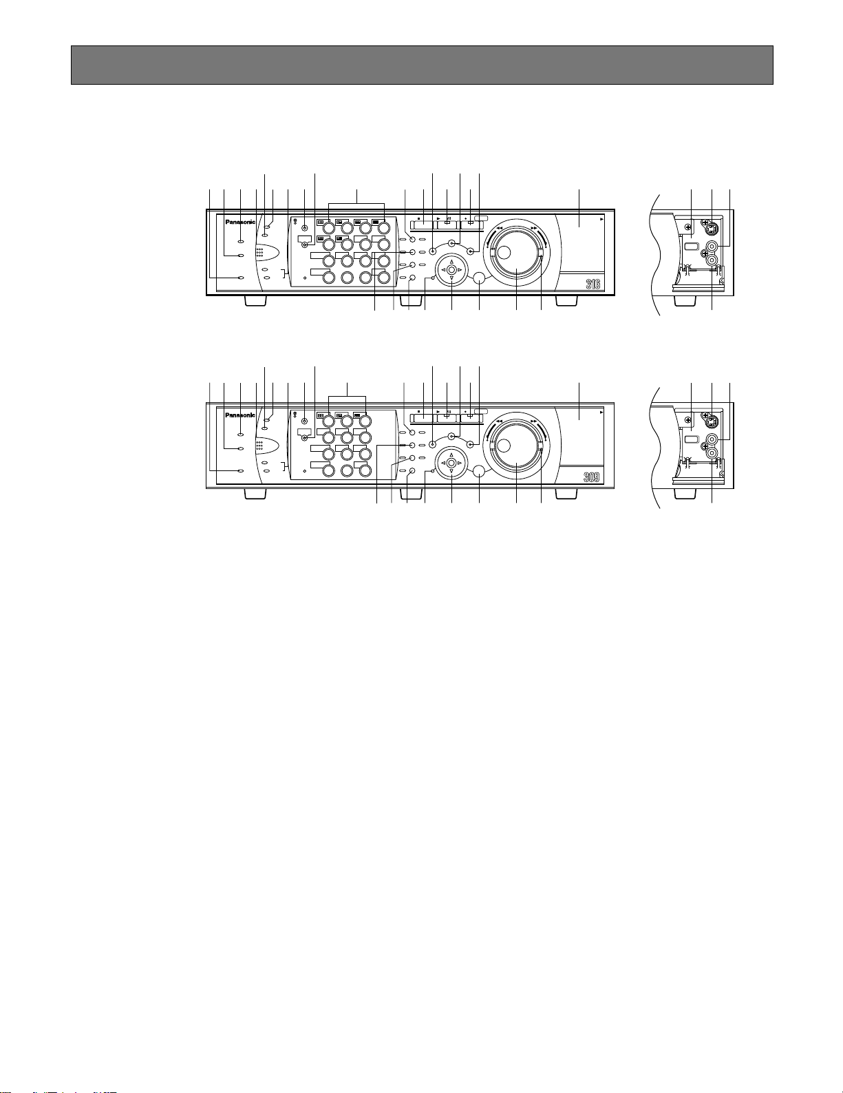
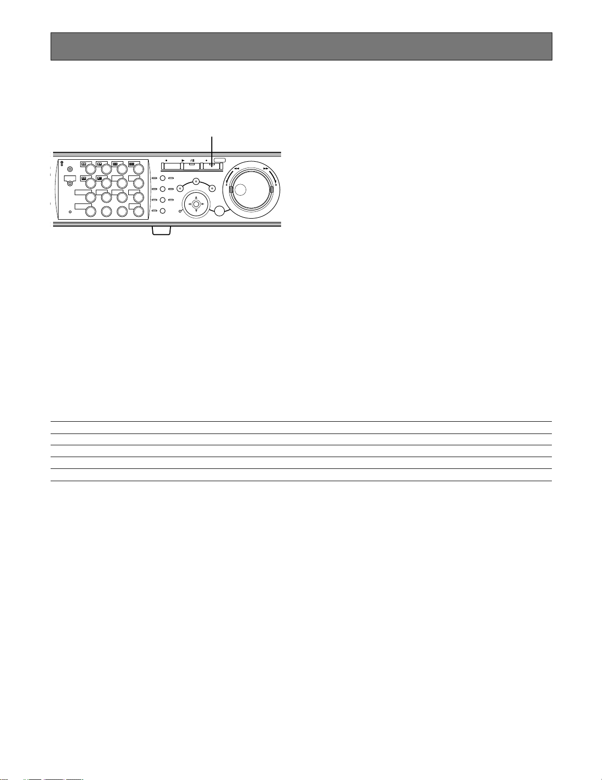
■ Front View
q Operate Indicator (OPERATE)
Lights up when the power is turned on.
w Alarm Suspension Indicator (ALARM SUSPEND)
Lights up when the alarm suspension mode is selected.
e Alarm Indicator (ALARM)
Blinks when an alarm occurs, and lights steadily when
the activated alarm is reset automatically.
To turn this indicator off, press the ALARM RESET button.
r Alarm Reset Button (ALARM RESET)
Pressing this button cancels alarm activation, and
returns the system to the condition before the alarm
was activated.
t Error indicator (ERROR)
Blinks orange when an error occurs that will not keep
the unit from running.
Blinks red when an error occurs that may cause the
system to go down.
Refer to page 60 for further information about error/
warnings.
y Timer Indicator (TIMER)
Lights up when the schedule recording is set, and
blinks while the schedule recording is being performed.
u HDD Access Indicators (HDD1/HDD2)
Blinks when the HDD1 or the HDD2 is accessed
respectively.
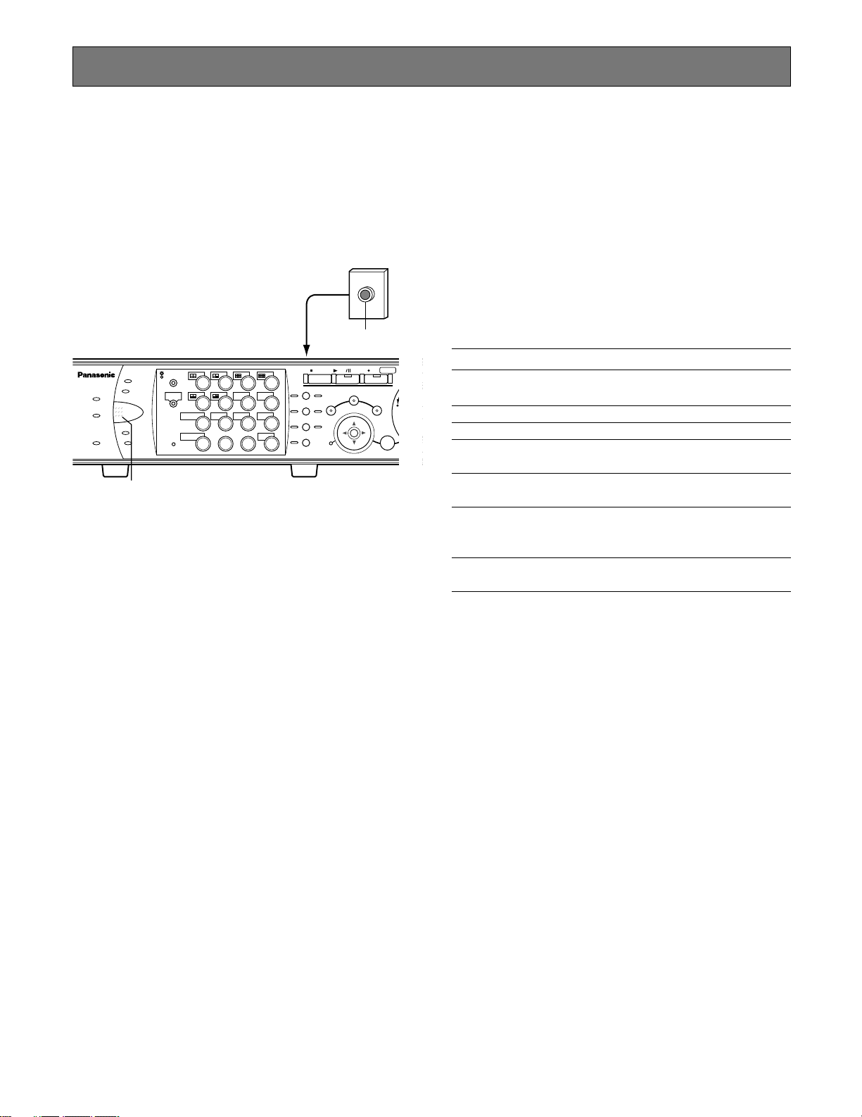
i Monitor Switch button (MONITOR1/MONITOR2)
Pressing this button switches the monitor. This button
lights up when monitor 1 is selected, and goes off when
monitor 2 or the VGA monitor is selected.
o Shift Button (SHIFT)
Toggles the functions of the camera selection buttons.
!0 Camera Selection Buttons ([1] - [10/0], [11] - [16] for
the WJ-HD316A, [1] - [9], [0] for the WJ-HD309A)
Pressing a button displays live or playback images of
the selected camera. The LED in the button indicates
the status as follows.
Green: When a button is lit green, the currently dis-
played image on the monitor is live from the respective camera.
Orange: When a button is lit orange, the image from the
respective camera is recorded.
Blue: When a button is lit blue, the currently displayed
image on the monitor is live from the respective
camera and is also recorded.
9
Page 10

When the shift button is lit, these buttons work as the
toggled function buttons.
(The buttons available as the toggled function buttons
will light green when the shift button is lit.)
!1 Pan, Tilt, Latest Recorded Image Playback Button
(PAN/TILT, GO TO LAST)
Pans/tilts the selected camera, or plays back the latest
recorded image.
(Refer to pages 45 and 23 respectively.)
!2 Zoom, Focus, A - B Repeat Button (ZOOM/FOCUS,
A-B REPEAT)
Zooms in/out, adjusts focus, or repeats playback of
recorded images between two designated points.
(Refer to pages 45 and 23 respectively.)
!3 Iris, Listing Button (IRIS, LISTED)
Adjusts iris, or enables/disables the filtering playback.
(Refer to pages 46 and 28 respectively.)
!4 Preset, Auto Function Button (PRESET/AUTO)
Moves a camera to the preset position, or activates the
auto function of the camera.
(Refer to pages 46 and 48 respectively.)
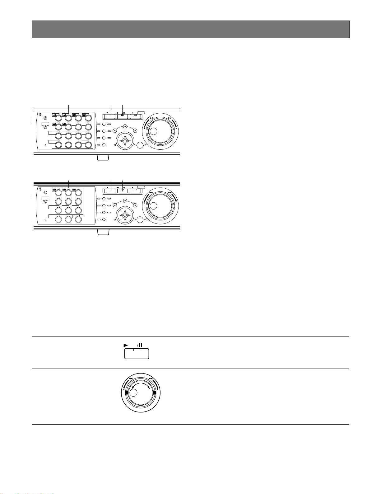
!5 Stop Button (STOP)
Stops playback.
!6 Play/Pause Button (PLAY/PAUSE)
Plays recorded images, or pauses playback.
!7 Record Button (REC/REC STOP)
Starts recording. To stop recording, press this button
down for 2 seconds or more.
!8 Slow Button (PAN/TILT, SLOW)
Pans/tilts the selected camera slowly.
@3 Set Button (SET)
Works differently depending on the situations listed
below:
• Plays recorded images at the current playback
speed when this button is pressed during fast playback.
• Registers preset positions of cameras.
• Activates the auto focus function.
• Resets the set iris.
• Sets the alarm suspension mode on/off.
• Determines the setting of parameters on the setup
menus.
@4 Jog Dial
Works differently depending on the situations as follows:
• Plays recorded images frame by frame when this
dial is rotated during pausing playback.
• Skips playback time when this dial is rotated during
playback at normal speed.
• Moves the cursor on the search menu or the thumbnail menu.
• Selects a parameter setting or a character on the
setup menus.
@5 Shuttle Ring
Works differently depending on the situations as follows:
• Plays fast when this ring is rotated during playback
at normal speed.
• Turns the search menu pages or the thumbnail
menu pages.
@6 Connectors Cover
@7 Copy Port (COPY2)
Connect a recommended external recording device to
this port.
!9 Search Button (SEARCH)
Displays the search menu.
@0 Setup, Escape Button (SETUP/ESC)
Displays the setup menu, or turns back to the previous
page of the setup menu, etc.
@1 Busy Indicator (BUSY)
Lights when the selected camera was not available to
operate because another user is operating it using a
controller or a PC via a network. In this case, wait until
this indicator goes off.
@2 Arrow Buttons (CDAB)
Adjusts zooming/focus, or moves the cursor on the
setup menus and the search menu.
10
@8 S-Video Output Connector (S-VIDEO)
Connect the S-video input connector of a VCR with this
connector. The same video signal supplied to the MONITOR OUT2 connector on the rear panel will be supplied to this connector.
@9 Video Output Connector (VIDEO OUT)
Connect the video input connector of a VCR with this
connector. The same video signal supplied to the MONITOR OUT2 connector on the rear panel will be supplied to this connector.
#0 Audio Output Connector (AUDIO OUT)
This connector, for an RCA standard jack, supplies an
unbalanced –10 dBV, 600 Ω line output audio signal to
an external device.
Recorded audio will be supplied from this connector
during playback.
The same audio signal supplied to the AUDIO OUT
connector on the rear panel will be supplied to this connector.
Page 11
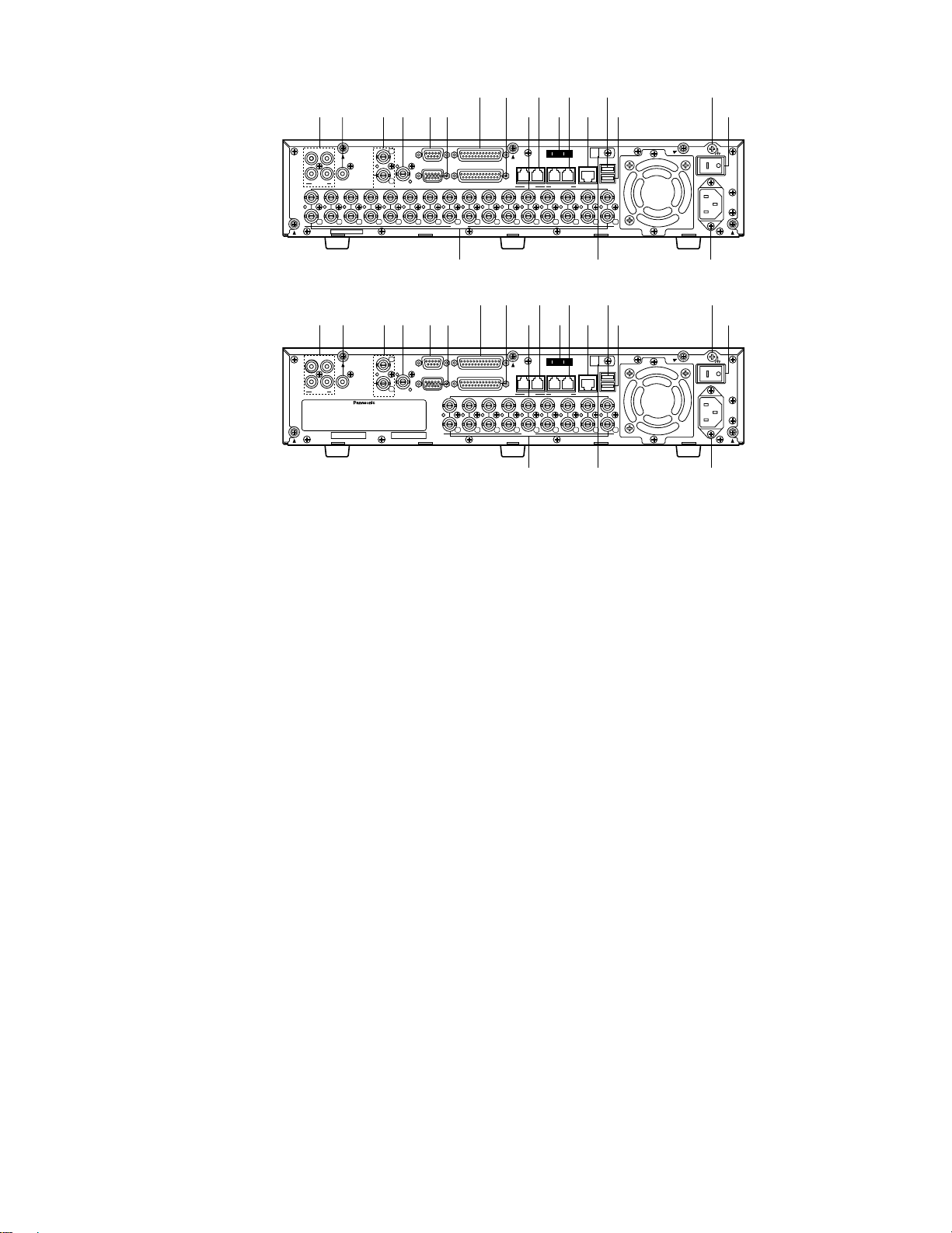
■ Rear View
[WJ-HD309A]
[WJ-HD316A]
IN
OUT
CASCADE
OUT
3
2
1
99887766554433221
1
12
VIDEO
AUDIO IN AUDIO OUT
PS· Data
MONITOR OUT CASCADE IN
MONITOR (VGA) ALARM/CONTROL
SERIAL ALARM
POWER
COPY 1
MODE
EXT STORAGE10/100BASE-TRS485(CAMERA)
DATA
AC IN
SIGNAL GND
1
4 2
1
18
2
IN
OUT
CASCADE
OUT
16
16
3
1515141413
2
1
13
12121111101099887766554433221
1
VIDEO
AUDIO IN AUDIO OUT
MONITOR OUT CASCADE IN
MONITOR (VGA) ALARM/CONTROL
SERIAL ALARM
POWER
COPY 1
MODE
EXT STORAGE10/100BASE-TRS485(CAMERA)
DATA
AC IN
SIGNAL GND
1
4 2
18
w t y ui
o !0 !1 !3 !5 !8
!2 !4 !6 !7e
r !9@0
w t y ui
o !0 !1 !3 !5 !8
!2 !4 !6 !7q e
r !9@0
q
q Audio Input Connectors (AUDIO IN 1 - 4)
These connectors, for RCA pin jacks, accept an unbalanced –10 dBV, 10 kΩ line input audio signal supplied
from an external device such as a microphone amplifier.
w Audio Output Connector (AUDIO OUT)
This connector, for an RCA standard jack, supplies an
unbalanced –10 dBV, 600 Ω line output audio signal to
an external device.
Recorded audio will be supplied from this connector
during playback.
e Video Input Connectors (CAMERA IN 1 - 16 for the
WJ-HD316A/CAMERA IN 1 - 9 for the WJ-HD309A)
Connect system cameras or combination cameras to
these BNC connectors. Refer to page 72 for the important notice about the BNC cables to be used.
A 75 Ω termination is made unless the video output terminal is connected.
To connect combination cameras, connect them to the
CAMERA IN 1 - 8 connectors of the WJ-HD316A, or the
CAMERA IN 1 - 6 of the WJ-HD309A (accept coaxial
communication).
r Video Output Connectors (CAMERA OUT 1 - 16 for
the WJ-HD316A/CAMERA OUT 1 - 9 for the WJHD309A)
These BNC connectors supply video signals looped
through the video input connectors. Refer to page 72
for the important notice about the BNC cables to be
used.
Note: Video signals will not be supplied from the CAM-
ERA OUT 1 - 8 connectors if the power of the unit is
off.
t Monitor Output Connectors (MONITOR OUT1, MONI-
TOR OUT2/CASCADE OUT)
Connect monitors to these BNC connectors. Refer to
page 72 for the important notice about the BNC cables
to be used.
The MONITOR OUT2 connector can also be used as
the CASCADE OUT connector.
When using two or more units of the WJ-HD316A/WJHD309A and using the MONITOR OUT2 connector as
the CASCADE OUT connector, connect with the CASCADE IN connector of another WJ-HD316A/WJHD309A.
y Cascade In Connector (CASCADE IN)
Connect with the CASCADE OUT connector of another
WJ-HD316A/WJ-HD309A when using two or more units
of the WJ-HD316A/WJ-HD309A.
u Serial Connector (SERIAL)
Connect a PC with this D-Sub 9-pin connector when
controlling this unit.
i Monitor Connector (MONITOR (VGA))
Connect a VGA monitor with this connector. The same
video signal supplied to the MONITOR OUT2 connector
will be supplied to this connector.
o Alarm Connector (ALARM)
Connect an external device such as a sensor or a door
switch with this D-Sub 25-pin connector.
!0 Alarm/Control Connector (ALARM/CONTROL)
Connect a control switch with this D-Sub 25-pin connector when controlling this unit using an external
device, or when controlling an alarm device such as a
buzzer or a lamp.
11
Page 12

!1 PS·Data Ports (DATA)
Connect PS·Data compatible devices with these ports.
!2 Mode Switches (MODE)
Set the operation mode of this unit with these dip
switches.
Important:
• The SETUP MENU will be displayed on monitor 2 and
the VGA monitor. (It is impossible to display the SETUP
MENU on monitor 1.)
• It will take around 2 minutes to display live images on
monitor 1 after turning on the power of the unit.
!3 RS485 Ports (RS485 (CAMERA))
Connect RS485 compatible combination cameras with
these ports.
!4 Network Port (10/100BASE-T)
Connect this unit to a network compatible with 10BASET or 100BASE-Tx when controlling this unit using a PC
via a network.
!5 Copy Port (COPY1)
Connect a recommended external recording device to
this port.
!6 Extra Storage Port (EXT STORAGE)
Connect an optional extension unit (WJ-HDE300 series)
with this port.
!7 Power Switch (POWER)
Turns the power of this unit on and off.
!8 Signal Ground Terminal (SIGNAL GND)
!9 Power Cord Inlet (AC IN)
Connect the power cord to this inlet.
@0 Cable Clamp
Fix the cables with this cable clamp to prevent disconnection or unstable connections that may cause recording failures or an unstable system.
1. Camera Title
Displays the edited camera title.
A position to display the camera title can be selected
from the following.
Upper left, upper right, lower left, lower right, center
The default camera title position is upper right (RUPPER).
Note: The camera title will be displayed with 16 charac-
ters (2 lines: 8 characters per line).
2. Time
Displays the current time (hour:minute:second) and
date (month:day:year).
A position to display the time can be selected from the
following.
Upper left, lower left, upper right, lower right
The default time display position is upper left (LUPPER).
Notes:
• When the camera title and the time display are layered, only the time display will be displayed.
• When monitor 1 is selected, it is possible to turn
on/off display of the camera title and the time by
pressing the camera selection button 8 for the WJHD316A (the camera selection button 6 for the WJHD309A) while the shift function is on (by pressing
the SHIFT button).
■ On Monitor 1 (To display only
live image)
q
q
q
The negative circled numbers indicate the default positions
of camera title q, time w and event display e.
q
wewe
q
wewe
3. Event Display
When an event has occurred, an event display will be
displayed.
The position of an event display will be symmetrical to
the position where the time is displayed. When the time
is displayed at the lower left of the screen, an event display will be displayed at the upper right corner of the
screen. The default position of an event display is the
upper right corner of the screen (R-UPPER).
The event display will be displayed differently as follows
depending on which event has occurred.
VMD-*: When motion is detected.
LOSS-*: When video loss has occurred.
COM-#: When a command alarm has occurred.
TRM-#: When a terminal alarm has occurred.
*: Camera number (1 - 16 for the WJ-HD316A, 1 - 9 for
the WJ-HD309A)
#: Alarm number
Note: Refer to page 49 for further information about
event types and event actions.
12
Page 13
■ On Monitor 2 (To display live or
recorded images)
q
q
1. Camera Title
Displays the edited camera title.
A position to display the camera title can be selected
from the following.
Upper left, upper right, lower left, lower right, center
The default camera title position is upper right (RUPPER).
w
B
–
q
q
w
–
C
q
w – A
The negative circled number q indicates the camera title
default position.
Notes:
• The same images displayed on monitor 2 will be displayed on the VGA monitor.
• The camera title will be displayed with 16 characters (2
lines: 8 characters per line).
• When monitor 2 is selected, it is possible to switch the
way of displaying the camera title in the following order
by pressing the camera selection button 8 for the WJHD316A (the camera selection button 6 for the WJHD309A) while the shift function is on (by pressing the
SHIFT button):
Display the camera title → Display the camera title in
list form → Not display the camera title
• When playing images recorded after selecting "ON" for
"Embedded REC (Time & Date)", the embedded abbreviation of the recording mode (event recording/emergency recording) will be displayed.
The abbreviations are as follows:
EVT: Pre-/post-event recording
EMR: Emergency recording
• In case that "ON" is selected for "Embedded REC (Title)"
and also "R-UPPER" or "R-LOWER" is selected for the
camera title position, when playing images recorded
with the resolution setting "SIF", a part of the embedded
camera title may not be displayed.
Important:
• Since the VGA output from this unit is the same as for
televisions (720 H x 480 V pixels/vertical frequency of
59.94 Hz), it may be possible that both the left and right
edges can not fit onto the screen depending on the
VGA monitor.
• It is impossible to use the MONITOR (VGA) connector
when connecting the unit in the cascade connection.
• It may take time to display live images on the VGA monitor if the VGA monitor is turned on/off when the unit is
running.
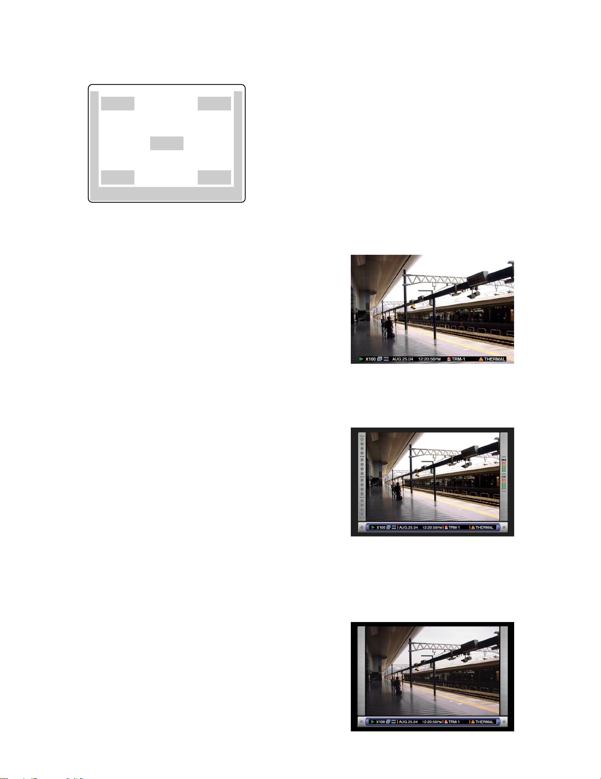
2. Task Bar
Displays the current status.
The task bar consists of the main bar (w - A), the left
bar (w - B), and the right bar (w - C).
There are 3 different ways to display the task bar as follows.
Mode 1
Displays only the main bar and the status is displayed
on it.
Mode 2
Displays the status on the main bar, the left bar and the
right bar.
Mode 3
Displays the status only on the main bar, and does not
display information on the left bar and the right bar.
Note: Mode 2 and Mode 3 are graphic operated. They
may not be as clear as Mode 1.
13
Page 14
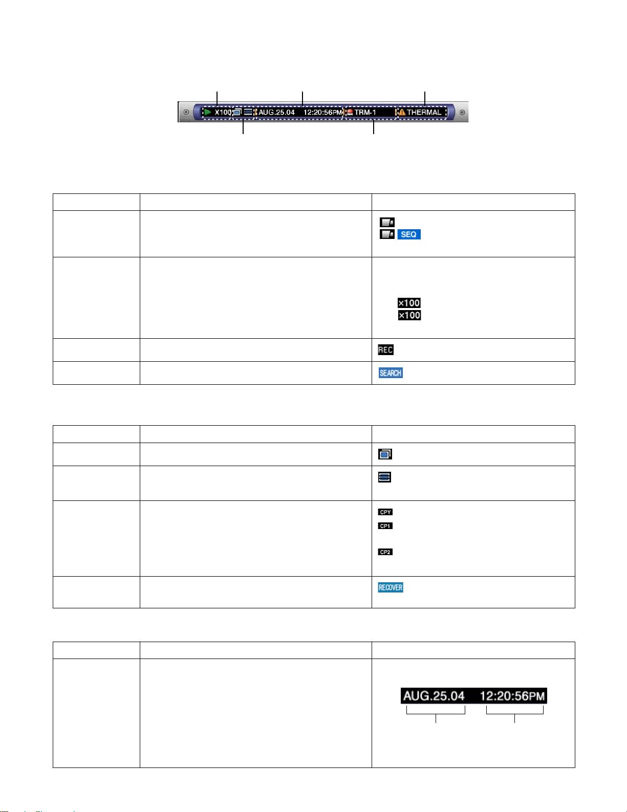
● Status on the Task Bar
q Status Display Area e Live/Playback Time Display Area
r Alarm Display Area
t Error Display Area
w Copy/Delete Icons, Selected Disk,
Mirror/RAID Recovery Display Area
• On the Main Bar
q Status Display Area
Indicated Item Status Indication
Live
Playback
Recording
Search Indicates that searching is currently being performed
w Copy/Delete Icons, Selected Disk, Mirror/RAID Recovery Display Area
Indicated Item
Copy Indicates that data copy is currently being performed
Delete
Selected Disk
Indicates the live image display status
Indicates that playback is currently being performed
with the displayed playback speed
Indicates that recording is currently being performed
Status Indication
Indicates that data deletion is currently being performed
Indicates the selected disk
: Live image is displayed
: Live images are displayed
sequentially
5: Currently playing
4: Currently playing in reverse
h: Currently pausing
2 : Currently playing at fast speed
1 : Currently playing in reverse at fast
speed
: Currently recording
: Currently searching
: Currently copying
: Currently deleting data
: Currently the HDD copy area is selected
: Currently the external recording device
connected to the COPY 1 port is selected
: Currently the external recording device
connected to the COPY 2 port is selected
RECOVER Indicates that mirror/RAID recovery is currently being
e Live/Playback Time Display Area
Indicated Item Status Indication
Time Displays time and date of the displayed image
14
performed
When displaying live image: Current time and
date
When playing recorded image: Time and date
when recorded
*: During summer time, an asterisk (*) will be dis-
played on the left side of the displayed time.
: Currently recovering mirror/RAID
Month:Day:Year Hour:Minute:Second
Page 15
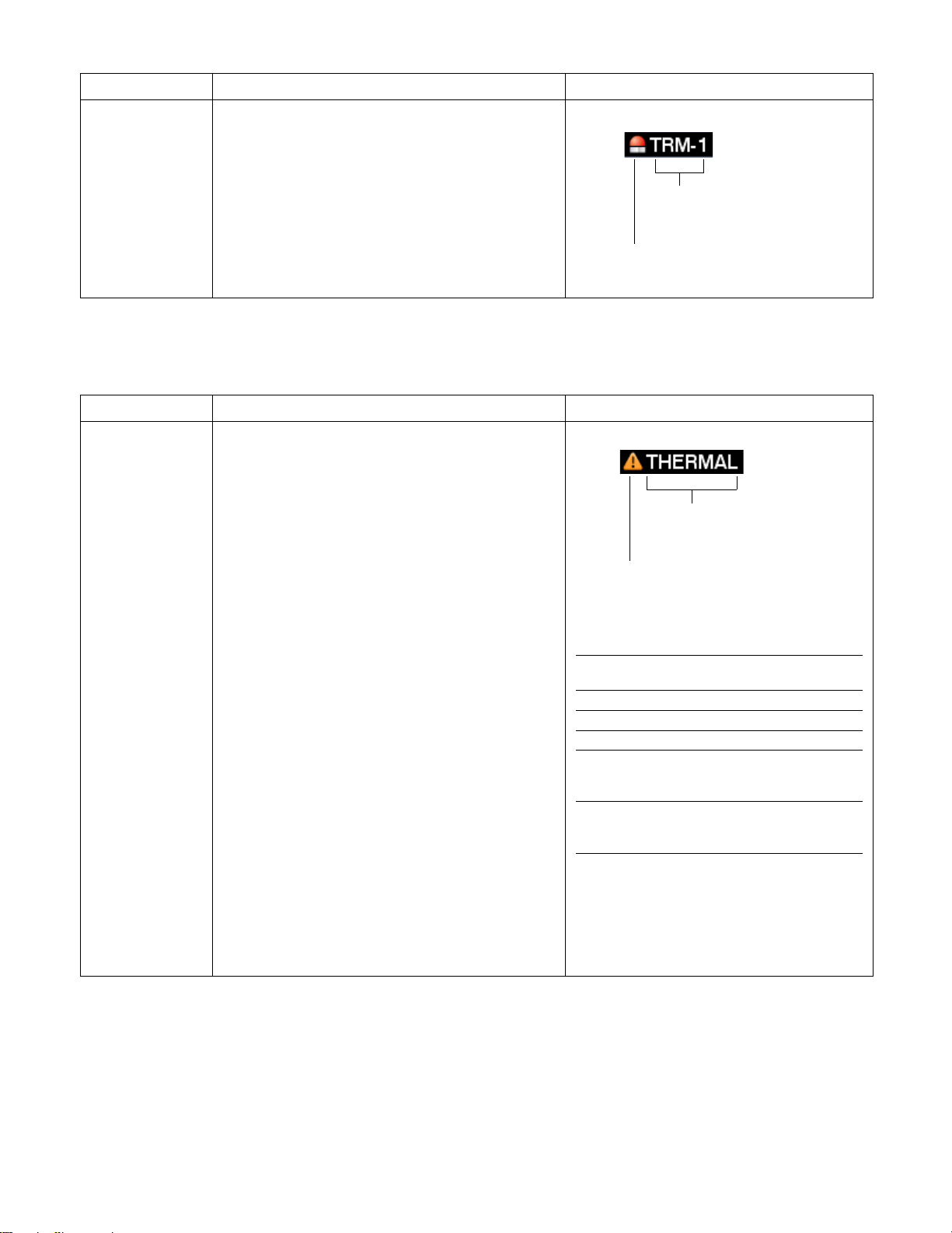
r Alarm Display Area
Indicated Item Status Indication
Alarm Indicates that an alarm has occurred
VMD-*: When motion is detected
LOSS-*: When video loss has occurred
COM-#: When a command alarm has occurred
TRM-#: When a terminal alarm has occurred
*: Camera number (1 - 16 for the WJ-HD316A, 1 - 9
for the WJ-HD309A)
#: Alarm number
Note: Refer to page 49 for further information about event types and event actions.
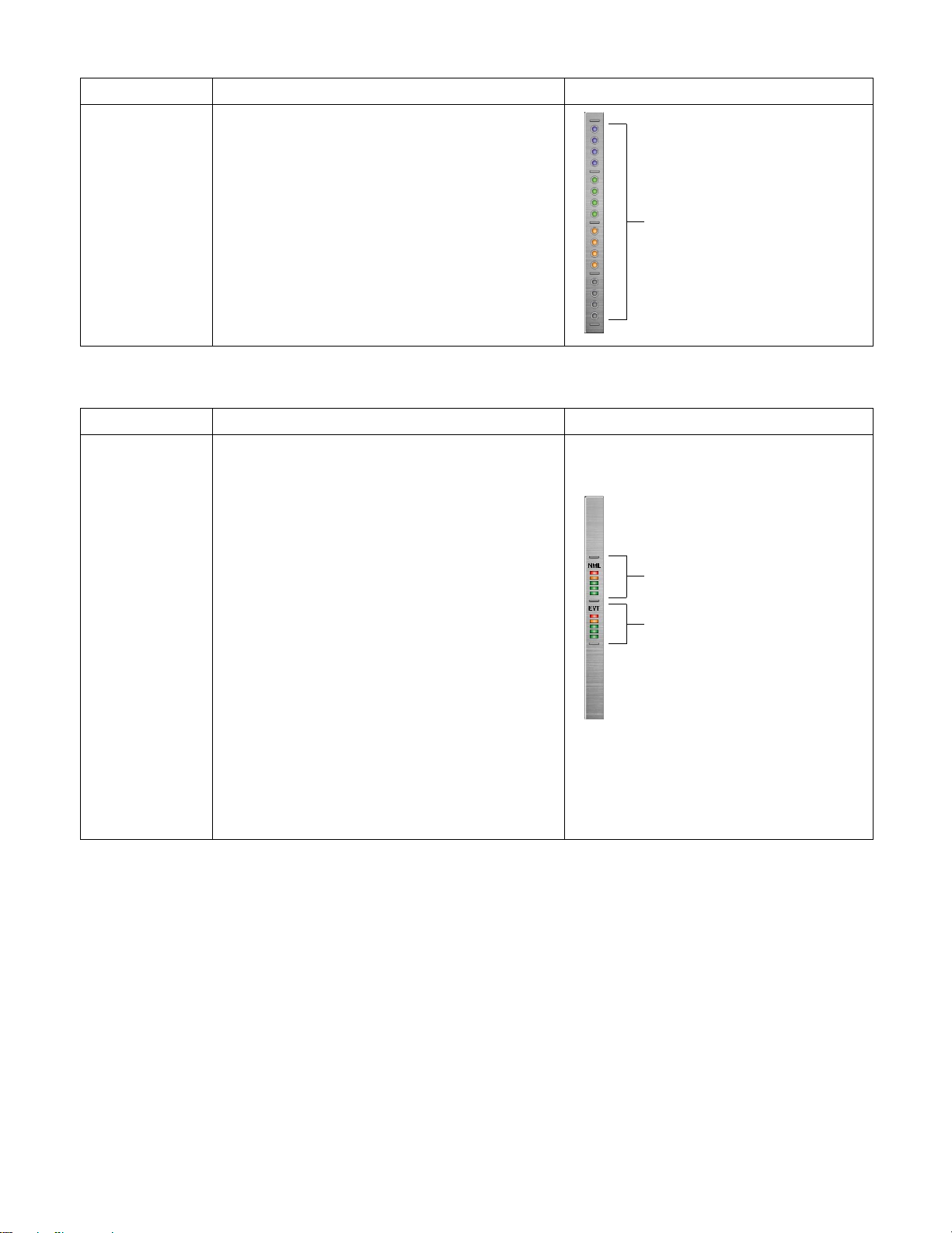
t Error Display Area
Indicated Item Status Indication
Error Warning Indicates an error occurrence or warning
ALT-*: Alteration is detected
W-ERROR: Failed to write data on the HDD
SMART: Warning of the HDD malfunction
H-METER: Set time for hour-meter (active time of
the HDD) warning has passed
THERMAL: The temperature inside the unit is too
high
POWER: A power outage has been detected
#-nn%: Warning about running out of disk space
while displaying available disk space percentage
#-FULL: No available disk space
MEDIUM-n: An error occurred in an external
recording device
REMOVE: The hard disk is removed from the sys-
tem automatically because of an access error
FAN: The fan is faulty
HDD-ERROR: The hard disk designated as
image storage was not found
M-FAIL: Mirror recovery failed
R-FAIL: RAID recovery failed
*: Camera number (1 - 16 for the WJ-HD316A, 1 - 9
for the WJ-HD309A)
#: Abbreviation that indicates partition
nn: Available disk size
n: Number of connector that an external recording
device is connected to
Abbreviation of partition
Status Displayed
Normal recording area NML
Event recording area EVT
Copy area CPY
External recording device
connected to the COPY1 port
on the rear panel CP1
External recording device
connected to the COPY2 port
on the front panel CP2
Alarm type
Alarm is occurring currently
Error type
Error is occurring currently
abbreviation
Notes:
• Refer to page 60 for further information about error types and what to do when an error has occurred.
• The RAID recovery is a function of the optional extension unit (WJ-HDE300 series). Refer to the Operating Instructions of
the optional extension unit for further information about the RAID recovery.
15
Page 16
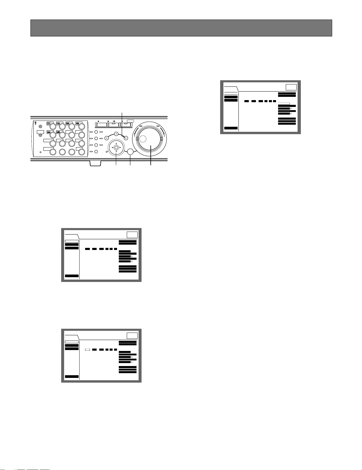
• On the Left Bar
Indicated Item
Camera Indicates recording and displaying status
Gray: Camera currently not displayed or not con-
nected to the respective channel
Green: Camera displayed on the monitor
Orange: Camera currently being recorded
Blue: Camera currently being recorded and dis-
played on the monitor
Status Indication
• On the Right Bar
Indicated Item
Used disk space
Indicates the available disk space of each partition.
Top: 100 % of the disk space is being used (no
available disk space)
Second from the top: 80 % of the disk space is
being used
Center: 60 % of the disk space is being used
Second from the bottom: 40 % of the disk space
is being used
Bottom: 20 % of the disk space is being used
Note: When "CONTINUE" is selected on the "Disk End
Mode" page of the "Maintenance" setup menu, the
available disk space will not be displayed. Refer
to a system administrator for further information.
Status Indication
Camera 1 is on the top and camera
16 is on the bottom
Normal Recording Area
Event Recording Area
NML: Available disk space of the normal record-
ing area used for manual recording and
schedule recording
EVT: Available disk space of the event recording
area used for event recording and emergency
recording
16
Page 17

STARTUP
z Insert the power plug to an outlet (AC 120 V,
60 Hz)
Note: Make sure the power source is AC 120 V, 60 Hz.
Important:
When using the optional extension unit (WJ-HDE300
series), turn on the power of this unit after turning on the
power of all extension units.
x Turn on the power switch on the rear panel.
The OPERATE indicator will light and the system check
(checking the system and hard disk) will start.
The startup splash image below will be displayed on monitor 2 and the VGA monitor during the system check.
When the auto login is off, the login window will be displayed if any button on the front panel of this unit is pressed
after the system check. (Go to step 3)
When the auto login is on, live images will be displayed
after the system check.
Notes:
• If the hard disk configuration was changed after the last
startup or the hard disk has problems, the HDD DISK
MENU will be displayed automatically after the startup
splash. (Refer to page 143 for further information.)
• It is possible to display the disk configuration menu by
pressing the SET button when the image shown below,
that says the system check has been completed, is displayed.
c Enter a user name and password.
Rotate the jog dial to select a character to be entered in the
cursor position.
It is also possible to enter numbers by pressing the camera
selection buttons ([1] - [10/0] for the WJ-HD316A, [1] - [9],
[0] for the WJ-HD309A).
To move the cursor, press the arrow buttons.
Use the same method to enter or edit characters attached
to images. Refer to page 59 for further information.
Notes:
• The default user name and password are as follows:
User name: ADMIN
Password: 12345
• To enhance the security, change the password for an
administrator before starting to run the unit. It is recommended to change the password for an administrator
periodically.
• To log out, press the LOGOUT button after confirming
that the SHIFT indicator is lit.
v Display a live image.
Press the SET button to display a live image.
If the authentication (login) window is displayed, enter the
user name and password.
When authenticated, a live image will be displayed.
When not authenticated, the authentication (login) window
will be displayed again.
Important:
The startup splash window will not be displayed on
monitor 1.
17
Page 18
CLOCK ADJUSTMENT
316
It is recommended to check the clock periodically and put
the clock right if it shows the wrong time.
Adjust the clock when displaying a live image.
Note: The following are the descriptions of how to adjust
the clock on the SETUP MENU (Quick). Refer to page
106 for descriptions of how to adjust the clock on the
SETUP MENU (Advanced).
zv
STOP
PLAY PAUSE
REC
-
SEARCH
SETUP
/ESC
REC STOP
SET
–
REV FWD
+
MONITOR1
MONITOR2
SHIFT SEQ
DISK SELECT
EL-ZOOM
2
1
5
6
COPY
9
10/0
1413
3
7
TEXT
11
LOGOUT
15 16
OSD
MARK
LOGOUT
4
8
12
PAN/
TILT
ZOOM/
FOCUS
IRIS
PRESET
/AUTO
GOTO
LAST
A-B
REPEAT
LISTED
PAN/TILT
SLOW
BUSY
c xxc
z Press the SETUP/ESC button for 2 seconds or
more.
The SETUP MENU (Quick) will be displayed on monitor 2
and the VGA monitor.
c Move the cursor to "SET" and press the SET
button.
The set time will be applied.
SETUP MENU
Quick
Display
REC & Event
Network
Advanced Menu
Date Format
■
Time Format
■
Time & Date
■
JAN . 1 . 04 10 00 00
Time & Date Display Position
■
Camera Title
■
Camera Title Display Position
■
Live Sequence
■
Summer Time (Day Light Savings)
■
Beep (Operation)
■
Language
■
::
MMM.DD.YY
12h
PM
SET
L-UPPER
SETUP
R-LOWER
SETUP
AUTO
ON
ENGLISH
LIVE
v Press the SETUP/ESC button for 2 seconds or
more.
The SETUP MENU (Quick) will disappear and a live image
will be displayed.
Important:
Recording will stop for around 4 seconds just after setting the clock.
SETUP MENU
Quick
Display
REC & Event
Network
Advanced Menu
Date Format
■
Time Format
■
Time & Date
■
JAN . 04 10 00 001 .
Time & Date Display Position
■
Camera Title
■
Camera Title Display Position
■
Live Sequence
■
Summer Time (Day Light Savings)
■
Beep (Operation)
■
Language
■
::
MMM.DD.YY
12h
PM
SET
L-UPPER
SETUP
R-LOWER
SETUP
AUTO
ON
ENGLISH
LIVE
x Move the cursor to "Time & Date" using the
arrows button (CDAB), and set the time
(Month, Day, Year, Time) using the jog dial.
SETUP MENU
Quick
Display
REC & Event
Network
Advanced Menu
Date Format
■
Time Format
■
Time & Date
■
JAN . 04 10 00 001 .
Time & Date Display Position
■
Camera Title
■
Camera Title Display Position
■
Live Sequence
■
Summer Time (Day Light Savings)
■
Beep (Operation)
■
Language
■
::
MMM.DD.YY
12h
PM
SET
L-UPPER
SETUP
R-LOWER
SETUP
AUTO
ON
ENGLISH
LIVE
18
Page 19

SHUTDOWN
To shutdown the unit, do the following.
When recording is being performed, press the REC button
for 2 or more seconds. Recording will stop and the indicator on the REC button will go off.
When playback is being performed, press the STOP button.
Playback will stop and the indicator on the PLAY/PAUSE
button will go off.
Turn off the power of the unit after confirming that the HDD1
and HDD2 indicators are off.
Important:
• Detach the plug from the outlet if not operating the unit
for a length of time.
• When the unit has not been used for a certain period,
turn on the power of the unit (approximately once a
week), and perform recording/playback to prevent
interferences with functions.
19
Page 20
R
R
316
RECORDING (Manual Recording)
Do the following to record manually.
Refer to a system administrator about the required settings
for manual recording.
x
z
STOP
PLAY PAUSE
REC
-
SEARCH
SETUP
/ESC
REC STOP
SET
–
REV FWD
+
MONITOR1
MONITOR2
SHIFT SEQ
DISK SELECT
EL-ZOOM
2
2
3
7
TEXT
11
LOGOUT
15 16
OSD
MARK
LOGOUT
4
8
12
PAN/
TILT
ZOOM/
FOCUS
IRIS
PRESET
/AUTO
GOTO
LAST
A-B
REPEAT
LISTED
PAN/TILT
SLOW
BUSY
1
5
6
COPY
9
10/0
1413
z Start recording.
Press the REC button to start recording.
The indicator on the button will light and recording will start.
Images from all the connected cameras will be recorded
with the default setting.
It is possible to record only images displayed on monitor 2
and the VGA monitor by changing the settings.
When recording with higher priority than manual recording
is performed, manual recording will not be performed until
this recording finishes.
Refer to the following about the recording mode.
x Stop recording.
Press the REC button down for around 2 seconds.
The indicator on the button will go off and recording will
stop.
Notes:
• The camera selection button will light orange (currently
recording) or blue (currently being recorded and displayed on the monitor) to indicate which camera is
being recorded.
• When recording with other recording modes being performed, the indicator on the REC button will not go off
even though the REC button is pressed to stop manual
recording.
• Manual recording will be stopped for a camera channel
when the supply of the video input signals to the camera channel is stopped. When the supply of the video
input signals to the camera channel is resumed, manual
recording will be performed automatically.
● Recording Mode and Priority
There are 4 recording modes as follows.
Recording Mode Description Priority
Emergency Recording Start recording manually using an external switch at an emergency event occurrence Highest
Event Recording Recording will be performed automatically at an event occurrence 1
Manual Recording Start and stop recording manually 2
Schedule Recording Recording will be performed automatically with a designated start/stop time and date 3
*1: Priorities on the above table are the default settings. (Emergency recording is the highest priority.)
*2: Priorities for manual recording, schedule recording and event recording can be changed. Refer to a system administrator
about the settings.
*1
*2
*2
*2
20
Page 21
RECORDING (Emergency Recording)
316
Record manually using an external switch at an emergency
event occurrence.
For example, install an external switch at the reception
counter, and start recording with it when a suspicious individual appears.
Refer to a system administrator about the required settings
for emergency recording.
External switch
z
STOP
PLAY PAUSE
REC
-
ALARM
ALARM
SUSPEND
OPERATE
ALARM
RESET
TIMER
ERROR
HDD 1
HDD 2
MONITOR1
MONITOR2
SHIFT SEQ
DISK SELECT
EL-ZOOM
2
1
5
6
COPY
9
10/0
1413
3
7
TEXT
11
LOGOUT
15 16
OSD
MARK
LOGOUT
4
8
12
PAN/
TILT
ZOOM/
FOCUS
IRIS
PRESET
/AUTO
GOTO
LAST
A-B
REPEAT
LISTED
PAN/TILT
BUSY
SLOW
SEARCH
SETUP
/ESC
REC STOP
–
SET
x
z Press the external switch.
The indicator on the REC button will light and recording will
start.
With the default setting, recording will be performed for 10
seconds.
• When starting emergency recording while another
recording with a different recording mode (except event
recording) is being performed, the indicator on the REC
button will remain lit and the other recording will resume
after the emergency recording has finished.
● Recording duration of emergency
recording
Recording duration of emergency recording can be set as
follows. Refer to a system administrator for further information.
Parameter Recording Duration
RE
1 s - 10 s Record for the selected time (1 - 10 sec-
onds, can be set in 1 second intervals)
20 s Record for 20 seconds
30 s Record for 30 seconds
1 min - 10 min Record for the selected time (1 -10 min-
utes can be set in 1 minute intervals)
20 min - 60 min Record for the selected time (20 - 60 min-
utes, can be set in 10 minutes intervals)
MANUAL Record only while the external switch is
being pressed down
(Record for at least 8 seconds)
CONTINUE Record until the ALARM RESET button is
pressed
Emergency recording is the highest priority. Emergency
recording will be performed even when this unit is recording in other recording modes.
x Stop recording.
When the recording duration set in advance has passed,
recording will stop automatically.
With the default setting, recording will stop automatically
after recording for 10 seconds.
When "CONTINUE" is selected for "Recording Time" of
"Emergency REC" on the SETUP MENU (Recording), press
the ALARM RESET button to stop recording.
The indicator on the REC button will go off and recording
will stop.
Notes:
• The camera selection button will light orange (currently
recording) or blue (currently being recorded and displayed on the monitor) to indicate which camera is
being recorded.
21
Page 22
PLAYBACK
2
It is possible to play recorded images without stopping
recording.
The playback images will be displayed on monitor 2 and
the VGA monitor.
[WJ-HD316A]
c
MONITOR1
MONITOR2
DISK SELECT
EL-ZOOM
13
z
1
2
3
4
PAN/
MARK
LOGOUT
TILT
8
ZOOM/
FOCUS
IRIS
12
PRESET
/AUTO
16
SEQSHIFT OSD
5
6
7
TEXT
COPY
9
10/0
11
14
15
STOP
GOTO
LAST
A-B
REPEAT
LISTED
PAN/TILT
SLOW
BUSY
x
PLAY PAUSE
SEARCH
REC
-
REC STOP
SETUP
/ESC
– +
SET
REV
FWD
[WJ-HD309A]
c
STOP
GOTO
LAST
A-B
REPEAT
LISTED
PAN/TILT
SLOW
BUSY
x
PLAY PAUSE
SEARCH
REC
-
REC STOP
SETUP
/ESC
– +
SET
REV
FWD
z
MONITOR1
MONITOR2
R
2
DISK SELECT
EL-ZOOM
1
4
7
2
TEXTSEQSHIFT OSD
5
COPY
8
0
MARK
LOGOUT
3
6
9
PAN/
TILT
ZOOM/
FOCUS
IRIS
PRESET
/AUTO
x Start playback.
Press the PLAY/PAUSE button.
The indicator on the PLAY/PAUSE button will light and the
recorded images of the selected camera will be played.
First playback after login: The latest recorded image will
be played.
With the default setting, playback will start 5 seconds
before the start time of the latest recorded image. The
start time can be selected from the following:
5 s/10 s/30 s/1 min/5 min
Refer to a system administrator about the settings.
Other than those above: Playback will start from the end
point of the recorded image played last time.
c Stop playback.
Press the STOP button.
The indicator on the PLAY/PAUSE button will go off and
playback will be stopped.
Live images will be displayed on monitor 2 and the VGA
monitor.
z Select the camera respective to the recorded
images to be played. (Go to step 2 if not necessary)
Press the desired camera selection button.
The pressed camera selection button will light green or
blue and the respective live images will be displayed.
● Available functions during playback
Pause Pressing the PLAY/PAUSE button to pause playback. While pausing,
Single frame skip Rotating the jog dial during pause will skip to the next or previous
PLAY PAUSE
REV
FWD
– +
the indicator on the PLAY/PAUSE button will blink.
Pressing this button again will resume playback.
frame.
Rotating the jog dial clockwise will skip to the next frame and rotating
it counterclockwise will skip to the previous frame.
22
Page 23
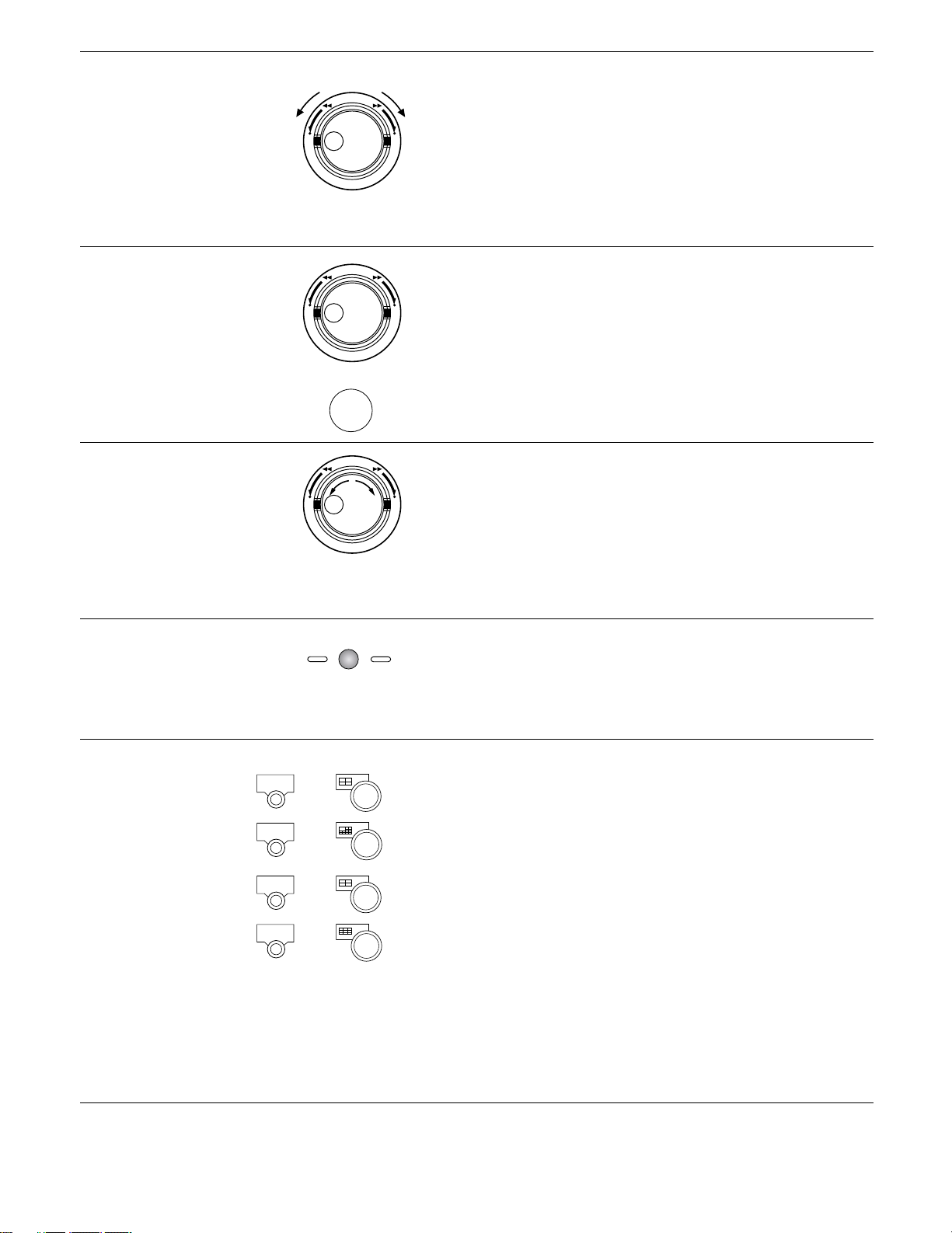
Fast forward/Fast reverse Rotating the shuttle ring will change the playback speed (1/2x, 1x, 2x,
5x, 10x, 20x) according to rotated degree. When the shuttle ring is
REV
FWD
held in the 20x position (rotated to the end) for 5 seconds, the playback speed will be 50x. When the shuttle ring is held 5 more seconds
– +
after the playback speed became 50x, the playback speed will be
100x.
Rotating the shuttle ring clockwise will play images at a faster speed
and rotating it counterclockwise will play images in reverse at a faster
speed.
To play at normal speed, release the shuttle ring.
Hold playback speed Press the SET button while holding the rotated shuttle ring to hold a
REV
FWD
– +
desired playback speed. (Playback speed will be held even though
the shuttle ring is released.)
To return to the normal playback speed, press the SET button.
+
SET
Skip Rotating the jog dial during playback will skip to the next or previous
Play the latest recorded image Press the GO TO LAST button to play the latest recorded image.
REV
FWD
– +
PA N/
TILT
GOTO
LAST
recorded image.
Rotating the jog dial clockwise will skip to the start time of the next
recording and start playback, and rotating it counterclockwise will
skip to the start time of the previous one. (Rotating the jog dial counterclockwise at a point shortly after the start time of the recording will
skip to the start time of the previous recording).
If there is no next or previous recorded image, current playback will
continue.
When the GO TO LAST button is pressed for 2 seconds or more while
displaying live images, playback of the latest recorded images will
start.
When the GO TO LAST button is pressed during recoding, it may happen that playback starts from not the latest recording time.
Multi-screen display It is possible to display recorded images in multi-screen format
(For the WJ-HD316A)
SHIFT
SHIFT
+
1
···
+
6
(4/7/9/10/13/16 for the WJ-HD316A, 4/7/9 for the WJ-HD309A).
q Press the SHIFT button. The SHIFT indicator will light.
w Press a camera selection button (1 - 6 for the WJ-HD316A, 1 - 3 for
the WJ-HD309A) to select a desired multi-screen.
Camera selection button 1: 4-split screen
Camera selection button 2: 7-split screen
(For the WJ-HD309A)
SHIFT
SHIFT
+
1
···
+
3
Camera selection button 3: 9-split screen
Camera selection button 4: 16-split screen (Only for the WJHD316A)
Camera selection button 5: 10-split screen (Only for the WJHD316A)
Camera selection button 6: 13-split screen (Only for the WJHD316A)
e To display recorded images on a single screen, press the SHIFT
button again.
After the SHIFT indicator goes off, press the camera selection button.
23
Page 24
Marking It is possible to play from a marked point. Do the following to mark a desired
point.
(For the WJ-HD316A)
SHIFT
MARK
+
12
1. Press the SHIFT button. The SHIFT indicator will light.
2. Press the camera selection button 12 (9 for the WJ-HD309A) (MARK) at a
desired point to be marked during playback.
(For the WJ-HD309A)
SHIFT
MARK
+
9
Up to 100 points can be marked. When more than 100 points are marked,
the older marked points will be overwritten by the newer marked points. In
this case, the oldest marked point is the first to be overwritten.
When marked while displaying in multi-screen, the same number of split
screens will be counted as marked points. (When a point is marked while
displaying a 16-split screen, 16 points will be marked simultaneously.)
Text display It is possible to display text information attached to a recorded image during
(For the WJ-HD316A)
SHIFT
TEXT
+
11
playback.
Text display is available only when playing on a single screen.
q Pause playback.
(For the WJ-HD309A)
SHIFT
TEXT
+
5
w Press the SHIFT button. The SHIFT indicator will light.
e Press the camera selection button 11 (5 for the WJ-HD309A) (TEXT).
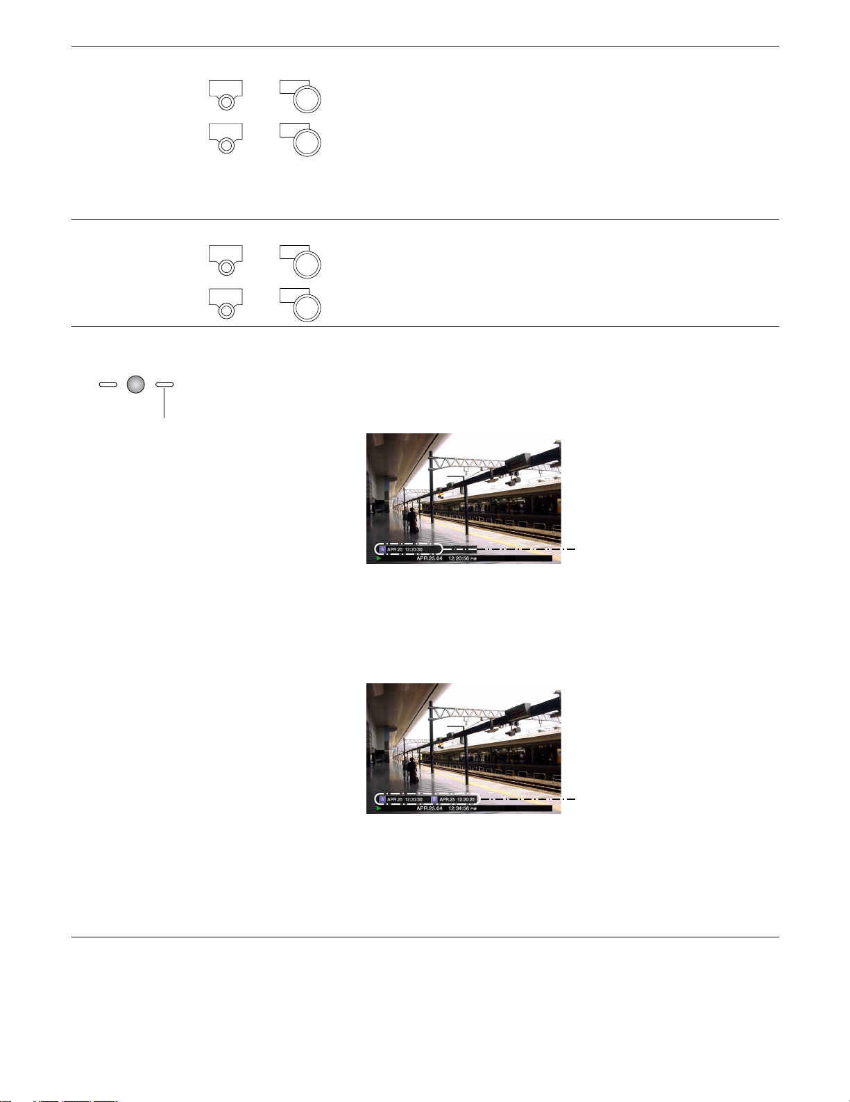
A - B repeat playback It is possible to play recorded images between two designated points repeat-
edly.
ZOOM/
FOCUS
A-B
REPEAT
q Designate a start point (A) by pressing the A - B REPEAT button during
playback.
The A - B REPEAT indicator will light, and the time of point A will be displayed.
Blink: During the A-B repeat playback
Light: When designating a start point (A)
Time of point A
To cancel the designated point, press the SETUP/ESC button.
w Designate an end point (B) by pressing the A - B REPEAT button during
playback.
When the start point and the end point are set, the A - B REPEAT indicator
will start blinking.
Playback between point A and B will start and keep playing repeatedly.
The time of point A and B will be displayed during playback.
Time of point A and B
e Press the A - B REPEAT button during A - B repeat playback to return to
normal playback.
Note: When the clock of the unit has been changed by editing the time
and date settings or by the auto time adjustment function, overlapping
of the time ranges of the images recorded before and after the time
adjustment could occur.
In this case, the A-B repeat playback may not function properly.
Notes:
• Playback will be paused if the playback time caught up with the recording time (present time) when recording and playback are performed simultaneously.
• When playing images recorded at a high recording rate, unsteady playback speed and audio break-up may occur.
• A black screen may sometimes be displayed during fast playback/fast reverse playback. This is a normal operation.
24
Page 25
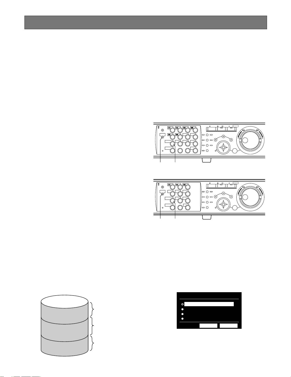
PLAYBACK IMAGE ON A DESIGNATED DISK
Images from a camera will be recorded on the built-in hard
disk or external recording devices (DVD-RAM drive, DVD-R
drive or CD-R drive) connected to this unit.
Available disk areas are as follows.
Note: External recording devices can be used as a copy
area for images recorded on the hard disk. It is impossible to record images on the external recording
devices directly.
HDD Normal Recording Area/Event Recording Area:
Recording area in the built-in hard disk of this unit.
Recorded images by manual recording (page 20) or
event recording will be stored in this area. There are 3
ways to search for a recorded image and play it when
"HDD normal area" or "event recording area" is selected
as the recording area.
• Search for a recording event and play it (Recording
event search) (page 28)
• Search for a motion detected time and date from
the recorded images and play it (VMD search)
(page 36)
• Search for a marked point and play it (Marking
search) (page 41)
HDD Copy Area: Recording area in the built-in hard disk of
this unit. Recorded images will be copied in this area.
There are 2 ways to search for a recorded image and
play it when "HDD copy area" is selected as the recording area.
• Search for a recording event and play it (Recording
event search) (page 28)
• Search for a motion detected time and date from
the recorded images and play it (VMD search)
(page 36)
Notes:
• Playback images will be displayed only on monitor 2
and the VGA monitor.
• Playback can be performed during recording.
• When a pre-recording area is created in an optional
extension unit, it is possible to play the images recorded on the pre-recording area.
• Disk space size of each recording area differs depending on the settings.
Refer to a system administrator for further information.
[WJ-HD316A]
STOP
PLAY PAUSE
REC
-
SEARCH
REC STOP
SETUP
/ESC
– +
SET
REV
FWD
MONITOR1
MONITOR2
DISK SELECT
EL-ZOOM
1
2
3
4
SEQSHIFT OSD
5
6
7
8
TEXT
COPY
9
13
10/0
14
MARK
11
12
LOGOUT
15
16
PAN/
TILT
ZOOM/
FOCUS
IRIS
PRESET
/AUTO
GOTO
LAST
A-B
REPEAT
LISTED
PAN/TILT
SLOW
BUSY
zx
[WJ-HD309A]
STOP
PLAY PAUSE
REC
-
SEARCH
REC STOP
SETUP
/ESC
– +
SET
REV
FWD
MONITOR1
MONITOR2
DISK SELECT
EL-ZOOM
1
4
7
2
TEXTSEQSHIFT OSD
5
COPY
8
0
MARK
LOGOUT
3
6
9
PAN/
TILT
ZOOM/
FOCUS
IRIS
PRESET
/AUTO
GOTO
LAST
A-B
REPEAT
LISTED
PAN/TILT
SLOW
BUSY
z x
COPY 1/COPY 2: Recording area in the external recording
device (DVD-RAM disk, DVD-R disk, CD-R disk) connected to the COPY 1 port or the COPY 2 port of the
unit. Recorded images will be copied in this area.
To search for a recorded image and play it when
"COPY 1" or "COPY 2" is selected as the recording area.
• Search for copy data and play it back (Copy Data
Search) (page 32)
Built-in hard disk
Recording area for
manual recording
Normal recording area
Event recording area
Copy area
and schedule
recording
Recording area for
event recording
and emergency
recording
Recording area for
copying
z Press the SHIFT button.
The SHIFT indicator will light.
x Press the camera selection button 9 (7 for the
WJ-HD309A) (DISK SELECT).
The DISK SELECT window will be displayed on monitor 2
and the VGA monitor.
DISK SELECT
HDD NORMAL/EVENT AREA
HDD COPY AREA
COPY 1
COPY 2
OK CANCEL
25
Page 26
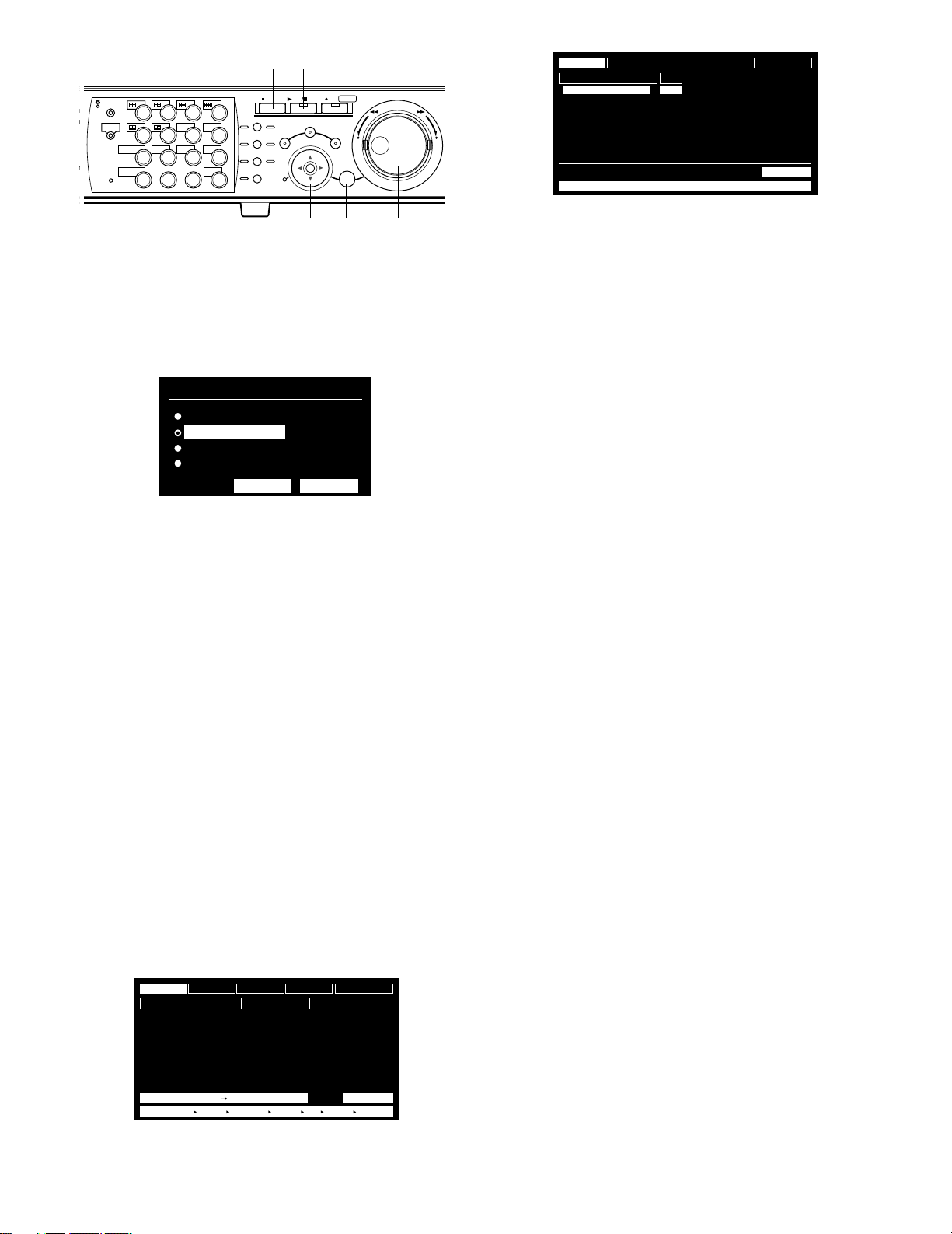
MONITOR1
316
MONITOR2
SHIFT SEQ
DISK SELECT
EL-ZOOM
2
n b
STOP
PLAY PAUSE
REC
-
REC STOP
2
3
7
TEXT
11
LOGOUT
15 16
OSD
MARK
LOGOUT
4
8
12
PAN/
TILT
ZOOM/
FOCUS
IRIS
PRESET
/AUTO
GOTO
LAST
A-B
REPEAT
LISTED
PAN/TILT
SLOW
BUSY
SEARCH
SETUP
/ESC
1
5
6
COPY
9
10/0
1413
REV FWD
–
SET
+
TIME&DATE
AUG.20.04 3:00:00 PM
AUG.19.04 2:29:00 PM
CAMERA
TIME&DATE
REC EVENT
CAM REC EVT
01ch
MANUAL
01ch
MANUAL
MANUAL
MANUAL
MANUAL
MANUAL
MANUAL
MANUAL
COPY DATA
TEXT
UNLOCK FILTER
ABCDEFGHIJ
ABCDEFGHIJ
ABCDEFGHIJ
ABCDEFGHIJ
ABCDEFGHIJ
ABCDEFGHIJ
ABCDEFGHIJ
ABCDEFGHIJ
TOTAL --
TEXT
cc cv
c Select a disk to be played using the jog dial
and move the cursor to "OK" using the arrows
button. Press the SET button to determine the
selection.
DISK SELECT
HDD NORMAL/EVENT AREA
HDD COPY AREA
COPY 1
COPY 2
OK CANCEL
When "HDD NORMAL/EVENT AREA" or "HDD COPY AREA"
is selected, the recording event list window will be displayed. (Refer to page 28 for further information about the
recording event list window.)
When "COPY 1" or "COPY 2" is selected, the copy data list
window will be displayed. (Refer to page 32 for further information about the copy data list window.)
To close the DISK SELECT window, move the cursor to
select "CANCEL" and press the SET button.
b Press the PLAY/PAUSE button to play the
selected recorded image.
The indicator on the PLAY/PAUSE button will light and playback will start.
Notes:
• When "COPY 1" or "COPY 2" is selected, audio will not
be heard.
• When "COPY1" or "COPY2" is selected, the reload
speed of recorded images may become slow during
playback of images recorded at a high recording rate.
n To stop playback, press the STOP button.
The indicator on the PLAY/PAUSE button will go off and
playback will stop.
Live images will be displayed on monitor 2 and the VGA
monitor.
Note: Pressing the PLAY/PAUSE button after stopping play-
back will start playback from the end point of the
recorded image played last time.
Important:
In the following cases, the recording event list
window/copy data list window will not be displayed
even when you move the cursor to "OK" and press the
SET button after selecting any of "HDD COPY AREA",
"COPY 1" or "COPY 2":
• When another user has selected the same area
• When copying is being performed manually in the
same area using a PC via a network
v Rotate the jog dial to select a desired recorded
image to be played.
TIME&DATE
AUG.20.04 3:04:23 PM
AUG.20.04 3:01:24 PM
AUG.20.04 3:00:40 PM
AUG.20.04 3:00:00 PM
AUG.20.04 2:59:11 PM
AUG.20.04 2:45:45 PM
AUG.20.04 2:44:09 PM
AUG.20.04 2:33:16 PM
CAMERA
TIME&DATE
TIME&DATE SEARCH REC EVENT SEARCH VMD SEARCH MARK
REC EVENT
CAM REC EVT
01ch
01ch
01ch
01ch
01ch
01ch
01ch
01ch
MANUAL
MANUAL
MANUAL
MANUAL
MANUAL
MANUAL
MANUAL
MANUAL
TEXT
UNLOCK FILTER
TEXT
ABCDEFGHIJ
ABCDEFGHIJ
ABCDEFGHIJ
ABCDEFGHIJ
ABCDEFGHIJ
ABCDEFGHIJ
ABCDEFGHIJ
ABCDEFGHIJ
TOTALAUG.20.04 3:22:10 AM AUG.20.04 2:31:18 AM 100
26
Page 27
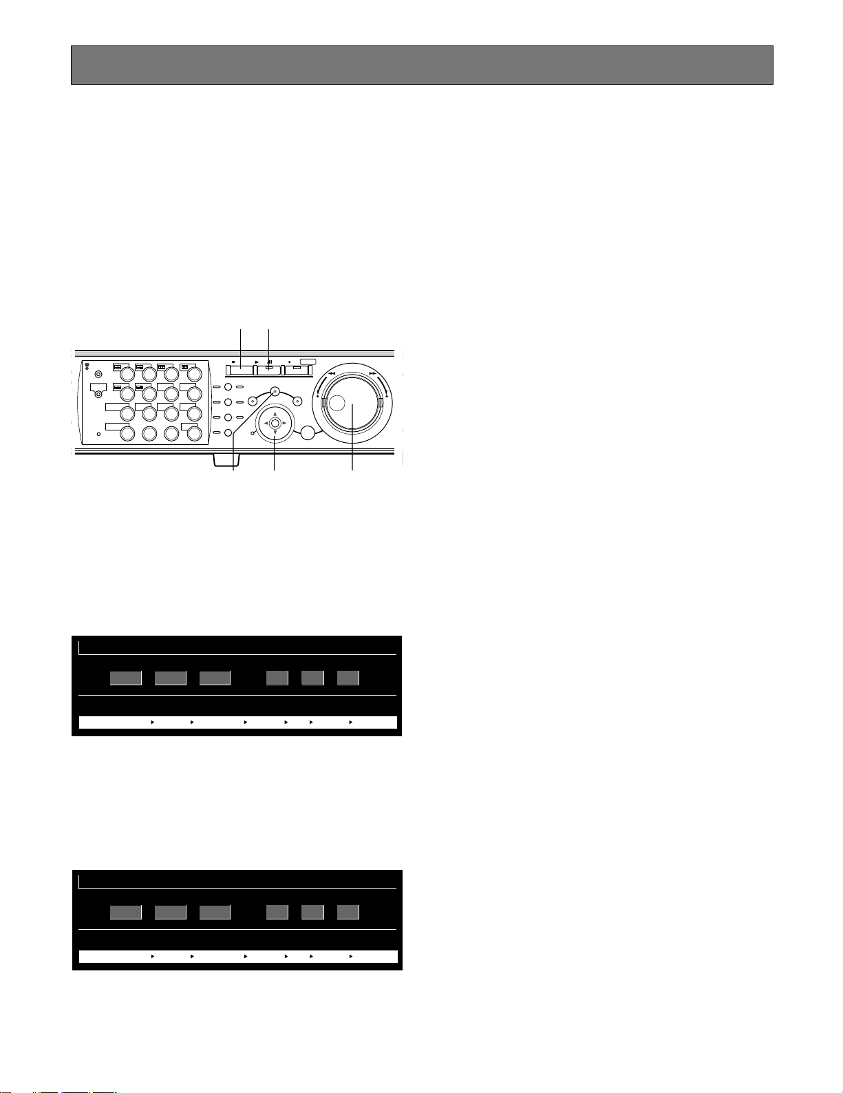
316
PLAYBACK FROM A DESIGNATED TIME AND DATE
Note: This feature is available only when "HDD NORMAL/
EVENT AREA" or "HDD COPY AREA" is selected with
the DISK SELECT window. When "COPY 1" or "COPY 2"
is selected, this feature is not available. Refer to page
25 for further information about the DISK SELECT window.
It is possible to play recorded images from a designated
time and date without stopping recording.
Playback images will be displayed on monitor 2 and the
VGA monitor.
v c
STOP
PLAY PAUSE
REC
-
SEARCH
SETUP
REC STOP
REV FWD
/ESC
–
SET
+
MONITOR1
MONITOR2
SHIFT SEQ
DISK SELECT
EL-ZOOM
2
2
3
7
TEXT
11
LOGOUT
15 16
OSD
MARK
LOGOUT
4
8
12
PAN/
TILT
ZOOM/
FOCUS
IRIS
PRESET
/AUTO
GOTO
LAST
A-B
REPEAT
LISTED
BUSY
PAN/TILT
SLOW
1
5
6
COPY
9
10/0
1413
xxz
c Press the PLAY/PAUSE button.
The indicator on the PLAY/PAUSE button will light and start
playback from the entered time and date.
If there is no recorded image after the entered time:
When there are images recorded after the entered time, the
oldest recorded image after the entered time will be played.
When there are no images recorded after the entered time,
the newest recorded image before the entered time will be
played.
v Press the STOP button.
The indicator on the PLAY/PAUSE button will go off and
stop playback.
Live images will be displayed on monitor 2 and the VGA
monitor.
z Press the SEARCH button repeatedly until the
time and date designation window is displayed.
The time and date designation window will be displayed on
monitor 2 and the VGA monitor.
START
JAN
TIME&DATE SEARCH REC EVENT SEARCH VMD SEARCH MARK
1
. .
04
: :
12 00 00 AM
x Enter the start time using the jog dial and the
arrows button.
Select the time and date using the jog dial. To move the
cursor, use the arrows button (AB).
START
FEB
2
. .
04
: :
12 00 00 AM
TIME&DATE SEARCH REC EVENT SEARCH VMD SEARCH MARK
27
Page 28
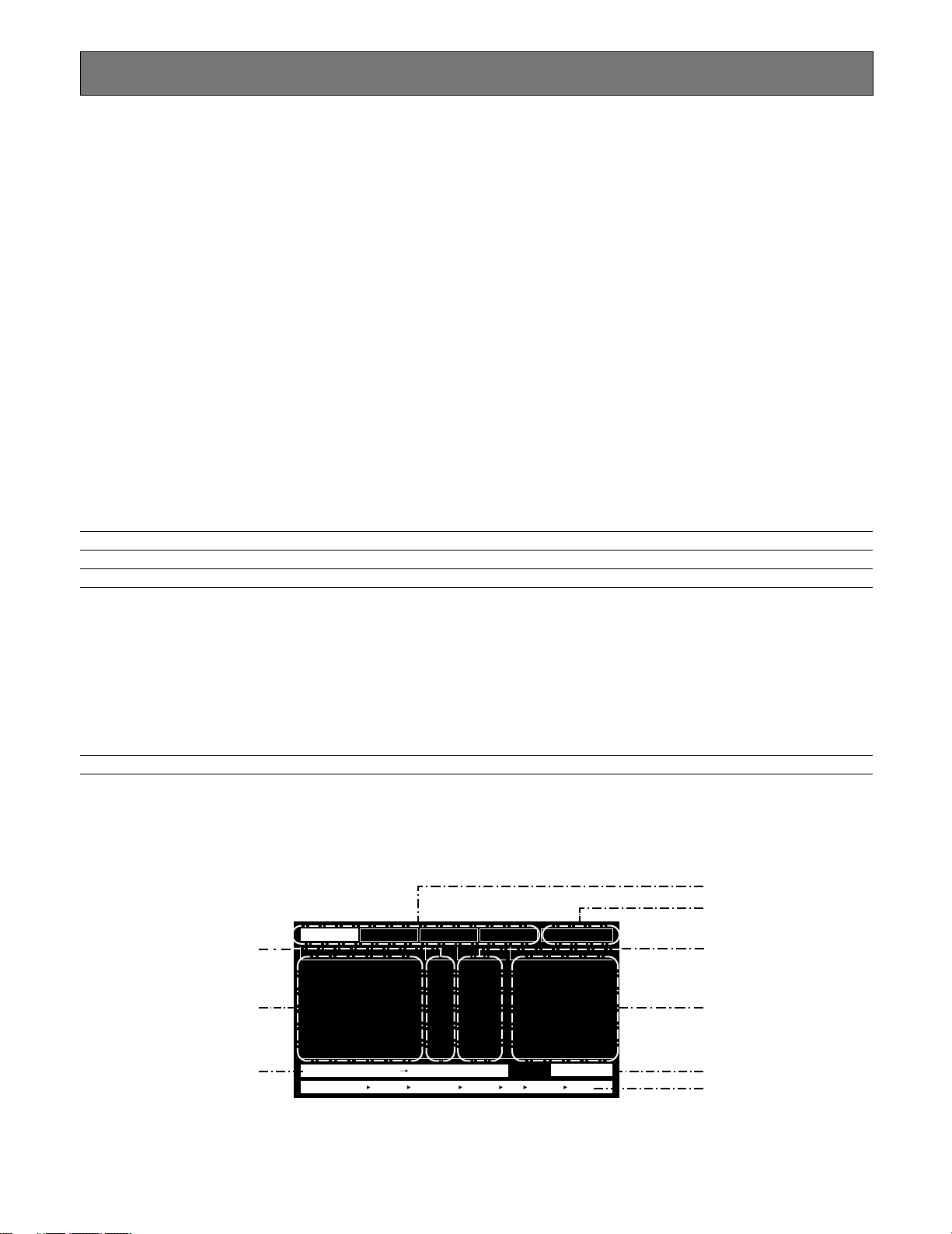
SEARCH AND PLAY
TIME&DATE
01ch
01ch
01ch
01ch
01ch
01ch
01ch
01ch
MANUAL
MANUAL
MANUAL
MANUAL
MANUAL
MANUAL
MANUAL
MANUAL
CAM REC EVT
ABCDEFGHIJ
ABCDEFGHIJ
ABCDEFGHIJ
ABCDEFGHIJ
ABCDEFGHIJ
ABCDEFGHIJ
ABCDEFGHIJ
ABCDEFGHIJ
TEXT
AUG.20.04 3:04:23 PM
AUG.20.04 3:01:24 PM
AUG.20.04 3:00:40 PM
AUG.20.04 3:00:00 PM
AUG.20.04 2:59:11 PM
AUG.20.04 2:45:45 PM
AUG.20.04 2:44:09 PM
AUG.20.04 2:33:16 PM
TIME&DATE SEARCH REC EVENT SEARCH VMD SEARCH MARK
TIME&DATE
CAMERA
REC EVENT
TEXT
UNLOCK FILTER
TOTALAUG.20.04 3:22:10 AM AUG.20.04 2:31:18 AM 100
There are 3 ways to search for a recorded image and play it when "HDD NORMAL/EVENT AREA" or "HDD COPY AREA" is
selected with the DISK SELECT window.
• Search for a recording event and play it (Recording event search) (see below)
• Search for a motion detected time and date from the recorded images and play it (VMD search) (page 36)
• Search for a marked point and play it (Marking search) (page 41)
When "COPY 1" or "COPY 2" is selected with the DISK SELECT window, the following is available.
• Search for copied recorded images and play it back (Copy Data Search) (page 32)
Note: Playback images will be displayed on a single screen on monitor 2 and the VGA monitor. To play in a multi-screen,
switch to a multi-screen after starting playback.
■ Search for a Recording Event and Play it (Recording Event Search)
Note: This feature is available only when "HDD NORMAL/EVENT AREA" or "HDD COPY AREA" is selected with the DISK
SELECT window. When "COPY 1" or "COPY 2" is selected, this feature is not available. Refer to page 25 for further information about the DISK SELECT window.
Display a list or a thumbnail of recording events, and select the desired recording event from them to play it.
It is possible to search using the following filters:
Search Filters
TIME & DATE Search for only images recorded in the entered time range.
CAMERA Search for only recorded images from the selected camera channel.
REC EVENT Search for only images recorded in the selected recording mode.
It is possible to search for images recorded in the following recording modes:
EMERGENCY: Emergency recording (Refer to page 21.)
VMD: Event recording performed when motion was detected.
TERMINAL: Event recording performed when a terminal alarm was detected.
COMMAND: Event recording performed when a command alarm was detected.
VIDEO LOSS: Event recording performed when video loss occurred.
MANUAL: Manual recording (Refer to page 20.)
SCHEDULE: Schedule recording (Refer to page 119.)
TEXT Search for only images recorded with text information.
● Recording Event List Window
Camera channel
Search filter buttons
Filter cancel button
Recording event
Time and date
28
Time range of the listed data
Text information
Number of the listed data
Search information
Page 29
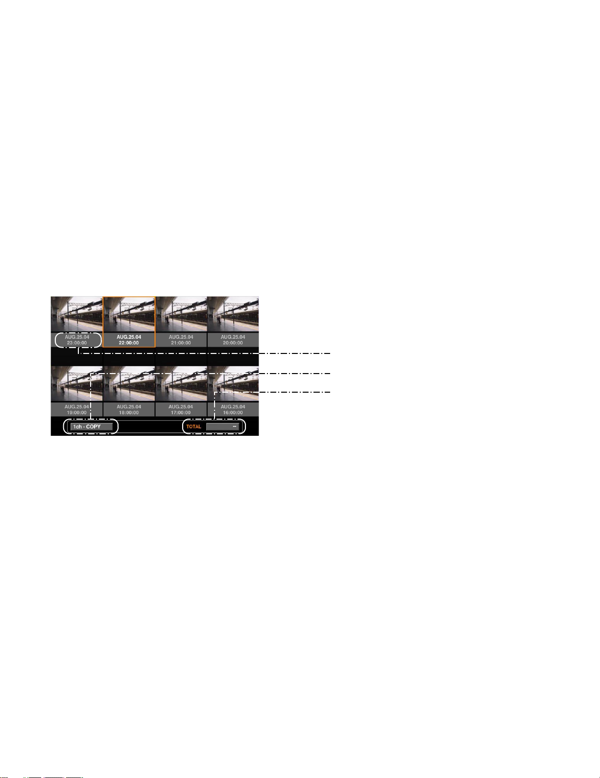
Search filter buttons: Selects the search filter
Filter cancel button: Cancels the selected search filter and lists all recording events
Time and date: <When searched by recording event>
The time when recording started will be displayed.
<When searched by VMD>
The time when motion was detected will be displayed.
<When searched by marked point>
The time when the point was marked will be displayed.
Camera channel: The camera channel of the recorded image will be displayed. The recorded image of
the displayed camera channel will be played on a single screen.
Recording event: The recording mode will be displayed.
Text information: The first several characters of text information will be displayed if the image has text
information.
Time range of the listed data: The time range of the listed data will be displayed.
Number of the listed data: The number of the listed data will be displayed.
Search information: The search filter will be displayed. (A filter of the currently displayed list will be dis-
played in orange.)
● Recording Event Thumbnail Window
Time and date
Camera channel/Recording event
Number of the listed data
Time and date: <When searched by recording event>
The time when recording started will be displayed.
<When searched by VMD>
The time when motion was detected will be displayed.
<When searched by marked point>
The time when the point was marked will be displayed.
Camera channel/Recording event: The camera channel of the recorded image will be displayed. The recorded image of
the displayed camera channel will be played on a single screen. The recording mode
also will be displayed.
Number of the listed data: The number of the listed data will be displayed.
Notes:
• Some images displayed in the thumbnail window may not match with their respective displayed recorded time due to playing of compressed recorded images.
• When the clock of the unit has been changed by editing the time and date settings or by the auto time adjustment function,
overlapping of the time ranges of the images recorded before and after the time adjustment could occur. In this case, the
thumbnail display may not function properly.
29
Page 30
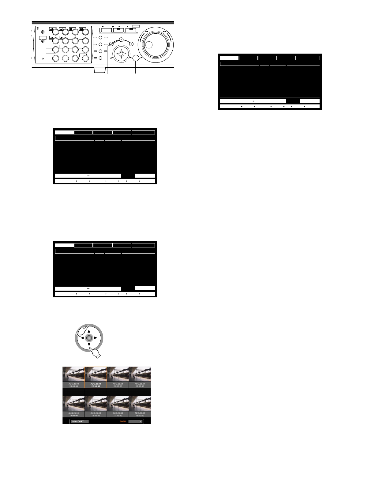
316
STOP
PLAY PAUSE
REC
-
SEARCH
SETUP
/ESC
REC STOP
SET
x
–
REV FWD
+
MONITOR1
MONITOR2
SHIFT SEQ
DISK SELECT
EL-ZOOM
2
1
5
6
COPY
9
10/0
1413
3
7
TEXT
11
LOGOUT
15 16
OSD
MARK
LOGOUT
4
8
12
PAN/
TILT
ZOOM/
FOCUS
IRIS
PRESET
/AUTO
GOTO
LAST
A-B
REPEAT
LISTED
PAN/TILT
SLOW
BUSY
zz
x
z Press the SEARCH button repeatedly until the
recording event list window is displayed.
TIME&DATE
AUG.20.04 3:04:23 PM
AUG.20.04 3:01:24 PM
AUG.20.04 3:00:40 PM
AUG.20.04 3:00:00 PM
AUG.20.04 2:59:11 PM
AUG.20.04 2:45:45 PM
AUG.20.04 2:44:09 PM
AUG.20.04 2:33:16 PM
The recording event list window will be displayed on monitor 2 and the VGA monitor.
Use the arrows button (CD) to switch between displaying
the list window and the thumbnail window alternately.
To search using a search filter, go to step 4.
CAMERA
TIME&DATE
TIME&DATE SEARCH REC EVENT SEARCH VMD SEARCH MARK
REC EVENT
CAM REC EVT
01ch
01ch
01ch
01ch
01ch
01ch
01ch
01ch
MANUAL
MANUAL
MANUAL
MANUAL
MANUAL
MANUAL
MANUAL
MANUAL
TEXT
UNLOCK FILTER
TEXT
ABCDEFGHIJ
ABCDEFGHIJ
ABCDEFGHIJ
ABCDEFGHIJ
ABCDEFGHIJ
ABCDEFGHIJ
ABCDEFGHIJ
ABCDEFGHIJ
TOTALAUG.20.04 3:22:10 AM AUG.20.04 2:31:18 AM 100
x Use the arrows button (AB) to select a search
filter (TIME & DATE, CAMERA, REC EVENT,
TEXT), and press the SET button.
TIME&DATE
AUG.20.04 3:04:23 PM
AUG.20.04 3:01:24 PM
AUG.20.04 3:00:40 PM
AUG.20.04 3:00:00 PM
AUG.20.04 2:59:11 PM
AUG.20.04 2:45:45 PM
AUG.20.04 2:44:09 PM
AUG.20.04 2:33:16 PM
When a search filter is selected, the respective search filter
window will be displayed.
Select "UNLOCK FILTER" and press the SET button to cancel the selected filter.
Refer to page 28 about search filters.
CAMERA
TIME&DATE
TIME&DATE SEARCH REC EVENT SEARCH VMD SEARCH MARK
REC EVENT
CAM REC EVT
01ch
01ch
01ch
01ch
01ch
01ch
01ch
01ch
MANUAL
MANUAL
MANUAL
MANUAL
MANUAL
MANUAL
MANUAL
MANUAL
TEXT
UNLOCK FILTER
ABCDEFGHIJ
ABCDEFGHIJ
ABCDEFGHIJ
ABCDEFGHIJ
ABCDEFGHIJ
ABCDEFGHIJ
ABCDEFGHIJ
ABCDEFGHIJ
TOTALAUG.20.04 3:22:10 AM AUG.20.04 2:31:18 AM 100
TEXT
TIME&DATE
AUG.20.04 3:04:23 PM
AUG.20.04 3:01:24 PM
AUG.20.04 3:00:40 PM
AUG.20.04 3:00:00 PM
AUG.20.04 2:59:11 PM
AUG.20.04 2:45:45 PM
AUG.20.04 2:44:09 PM
AUG.20.04 2:33:16 PM
CAMERA
TIME&DATE
TIME&DATE SEARCH REC EVENT SEARCH VMD SEARCH MARK
REC EVENT
CAM REC EVT
01ch
01ch
01ch
01ch
01ch
01ch
01ch
01ch
MANUAL
MANUAL
MANUAL
MANUAL
MANUAL
MANUAL
MANUAL
MANUAL
TEXT
UNLOCK FILTER
TEXT
ABCDEFGHIJ
ABCDEFGHIJ
ABCDEFGHIJ
ABCDEFGHIJ
ABCDEFGHIJ
ABCDEFGHIJ
ABCDEFGHIJ
ABCDEFGHIJ
TOTALAUG.20.04 3:22:10 AM AUG.20.04 2:31:18 AM 100
<List window>
⇔
30
<Thumbnail window>
Page 31

MONITOR1
316
MONITOR2
SHIFT SEQ
DISK SELECT
EL-ZOOM
2
b
STOP
PLAY PAUSE
REC
-
REC STOP
2
3
7
TEXT
11
LOGOUT
15 16
OSD
MARK
LOGOUT
4
8
12
PAN/
TILT
ZOOM/
FOCUS
IRIS
PRESET
/AUTO
GOTO
LAST
A-B
REPEAT
LISTED
BUSY
PAN/TILT
SLOW
SEARCH
SETUP
/ESC
1
5
6
COPY
9
10/0
1413
REV FWD
–
SET
ccc
c
+
v
Filter recording events by the recording event
REC EVENT FILTERING
EMERGENCY
VMD
TERMINAL
COMMAND
VIDEO LOSS
MANUAL
SCHEDULE
SET : [ SET ] CANCEL : [ ESC ]
OFF
ON
ON
ON
ON
ON
ON
c Filter recording events.
Filter recording events by time and date
TIME&DATE FILTERING
■
START
..
JAN 104
END
..
JAN 1 04 12 00
SET : [SET] CANCEL : [ESC]
Move the cursor using the arrows button and rotate the jog
dial to enter the time and date.
Press the SET button to determine the entered time and
date.
The recording event in the entered time range will be listed
and displayed.
Filter recording events by camera channel
CAMERA FILTERING
CAMERA
1
2345
9 10 11 12 13 14 15 16
SET : [ SET ] CANCEL : [ ESC ]
Select camera channel numbers (1 - 16 for the WJHD316A, 1 - 9 for the WJ-HD309A) using the arrows button
to move the cursor, and rotate the jog dial to apply filtering.
It is possible to select camera channels using the camera
selection buttons [1] - [16] for the WJ-HD316A ([1] - [9] for
the WJ-HD309A).
The selected camera channels will turn white.
Press the SET button to determine the selection of camera
channel numbers.
The recording events of the selected camera channels will
be listed.
Note: When operating the system controller, select a cam-
era channel using the numeric keypad. In this case, it is
impossible to select 10 CH to 16 CH.
: AM
12 00
: AM
6 78
Move the cursor to select the recording event (refer to page
28) using the arrows button (CD) and rotate the jog dial to
ON.
Press the SET button to determine the selection.
The recording events of the selected filter will be listed.
Filter recording events by text information
TEXT FILTERING
WITHOUT TEXT
SET : [ SET ] CANCEL : [ ESC ]
Rotate the jog dial to select OFF, WITH TEXT or WITHOUT
TEXT.
Press the SET button to determine the selection.
The recording events filtered by the selected filter will be
listed.
v Rotate the jog dial to select the recording
event to be played.
TIME&DATE
AUG.20.04 3:04:23 PM
AUG.20.04 3:01:24 PM
AUG.20.04 3:00:40 PM
AUG.20.04 3:00:00 PM
AUG.20.04 2:59:11 PM
AUG.20.04 2:45:45 PM
AUG.20.04 2:44:09 PM
AUG.20.04 2:33:16 PM
It is possible to turn the page by rotating the shuttle ring.
CAMERA
TIME&DATE
TIME&DATE SEARCH REC EVENT SEARCH VMD SEARCH MARK
REC EVENT
CAM REC EVT
01ch
01ch
01ch
01ch
01ch
01ch
01ch
01ch
MANUAL
MANUAL
MANUAL
MANUAL
MANUAL
MANUAL
MANUAL
MANUAL
TEXT
UNLOCK FILTER
TEXT
ABCDEFGHIJ
ABCDEFGHIJ
ABCDEFGHIJ
ABCDEFGHIJ
ABCDEFGHIJ
ABCDEFGHIJ
ABCDEFGHIJ
ABCDEFGHIJ
TOTALAUG.20.04 3:22:10 AM AUG.20.04 2:31:18 AM 12345
b Press the PLAY/PAUSE button.
The LISTED indicator and the indicator on the PLAY/PAUSE
button will light and playback of the selected recording
event will start.
Note: When the LISTED indicator is lit, only listed recording
events are available to be played. Press the LISTED
button during playback to make all recording events
available to be played.
31
Page 32

316
Important:
TIME&DATE
01ch
01ch
01ch
01ch
01ch
01ch
01ch
01ch
MANUAL
MANUAL
MANUAL
MANUAL
MANUAL
MANUAL
MANUAL
MANUAL
CAM REC EVT
ABCDEFGHIJ
ABCDEFGHIJ
ABCDEFGHIJ
ABCDEFGHIJ
ABCDEFGHIJ
ABCDEFGHIJ
ABCDEFGHIJ
ABCDEFGHIJ
TEXT
AUG.20.04 3:04:23 PM
AUG.20.04 3:01:24 PM
AUG.20.04 3:00:40 PM
AUG.20.04 3:00:00 PM
AUG.20.04 2:59:11 PM
AUG.20.04 2:45:45 PM
AUG.20.04 2:44:09 PM
AUG.20.04 2:33:16 PM
TIME&DATE SEARCH REC EVENT SEARCH VMD SEARCH MARK
TIME&DATE
CAMERA
REC EVENT
TEXT
UNLOCK FILTER
TOTALAUG.20.04 3:22:10 AM AUG.20.04 2:31:18 AM --
In the recording event list, the start time of recording
will be displayed.
When events occurred successively, the contents of the
event log and the recording event list will not always
match since the unit continues to record the first occurring event.
MONITOR1
MONITOR2
SHIFT SEQ
DISK SELECT
EL-ZOOM
2
1
5
6
COPY
9
10/0
1413
3
7
TEXT
11
LOGOUT
15 16
OSD
MARK
LOGOUT
n
STOP
PLAY PAUSE
REC
-
REC STOP
4
8
12
PAN/
TILT
ZOOM/
FOCUS
IRIS
PRESET
/AUTO
GOTO
LAST
A-B
REPEAT
LISTED
PAN/TILT
SLOW
BUSY
SEARCH
SETUP
/ESC
REV FWD
–
SET
+
n To stop playback, press the STOP button.
The indicator on the PLAY/PAUSE button will go off and
playback will be stopped.
Live images will be displayed on monitor 2 and the VGA
monitor.
■ Search for Copied Recorded Images and Play it back (Copy Data
Search)
Note: This feature is available only when "COPY 1" or "COPY 2" is selected with the DISK SELECT window. When "HDD NOR-
MAL/EVENT AREA" or "HDD COPY AREA" is selected, this feature is not available. Refer to page 25 for further information
about the DISK SELECT window.
Display a list or a thumbnail of copied recorded images (Copy Data), and select the desired copy data file from them to play it.
It is possible to search using the following filters:
Search Filters
TIME & DATE Search for only images recorded in the entered time range.
CAMERA Search for only recorded images from the selected camera channel.
● Copy Data List Window
Camera channel
Time and date
Search filter buttons: Selects the search filter
Filter cancel button: Cancels the selected search filter and lists all copy data file
Time and date: The time when recording of the source of the copied recorded images had started will
Camera channel: The camera channel of the copy data file will be displayed. The recorded image of the
32
Search filter buttons
Filter cancel button
Number of the listed data
(Always "--" is displayed.)
be displayed.
displayed camera channel will be played on a single screen.
Page 33

● Copy Data Thumbnail Window
Time and date
Camera channel
Number of the listed data
(Always "--" is displayed.)
Time and date: The time when copying of the recorded images had started will be displayed.
Camera channel: The camera channel of the copy data file will be displayed. The recorded image of the
displayed camera channel will be played on a single screen. The recording mode also
will be displayed.
Notes:
• Some images displayed in the thumbnail window may not match with their respective displayed recorded time due to playing of compressed recorded images.
• When no image file was found for the searched time and date, the displayed time and date on the list/thumbnail window
may not matchthe start time of the recorded images to be played.
• If the copy completion is not performed for the CD-R/DVD-R disk, it is impossible to search/play copied recorded images
on the CD-R/DVD-R disk.
Refer to page 53 for further information about the copy completion.
• When the clock of the unit has been changed by editing the time and date settings or by the auto time adjustment function,
overlapping of the time ranges of the images recorded before and after the time adjustment could occur. In this case, the
thumbnail display may not function properly.
33
Page 34

316
STOP
PLAY PAUSE
REC
-
SEARCH
SETUP
/ESC
REC STOP
SET
x
–
REV FWD
+
MONITOR1
MONITOR2
SHIFT SEQ
DISK SELECT
EL-ZOOM
2
1
5
6
COPY
9
10/0
1413
3
7
TEXT
11
LOGOUT
15 16
OSD
MARK
LOGOUT
4
8
12
PAN/
TILT
ZOOM/
FOCUS
IRIS
PRESET
/AUTO
GOTO
LAST
A-B
REPEAT
LISTED
PAN/TILT
SLOW
BUSY
zz
x
z Press the SEARCH button repeatedly until the
copy data file list window is displayed.
TIME&DATE
AUG.20.04 3:00:00 PM
AUG.19.04 2:29:00 PM
The copy data file list window will be displayed on monitor
2 and the VGA monitor.
Use the arrows button (CD) to switch between displaying
the list window and the thumbnail window alternately.
To search using a search filter, go to step 4.
CAMERA
TIME&DATE
REC EVENT
CAM REC EVT
01ch
MANUAL
01ch
MANUAL
MANUAL
MANUAL
MANUAL
MANUAL
MANUAL
MANUAL
COPY DATA
TEXT
UNLOCK FILTER
ABCDEFGHIJ
ABCDEFGHIJ
ABCDEFGHIJ
ABCDEFGHIJ
ABCDEFGHIJ
ABCDEFGHIJ
ABCDEFGHIJ
ABCDEFGHIJ
TOTAL --
TEXT
x Use the arrows button (AB) to select a search
filter (TIME & DATE, CAMERA), and press the
SET button.
TIME&DATE
AUG.20.04 3:00:00 PM
AUG.19.04 2:29:00 PM
When a search filter is selected, the respective search filter
window will be displayed.
Select "UNLOCK FILTER" and press the SET button to cancel the selected filter.
Refer to page 28 about search filters.
CAMERA
TIME&DATE
REC EVENT
CAM REC EVT
01ch
MANUAL
01ch
MANUAL
MANUAL
MANUAL
MANUAL
MANUAL
MANUAL
MANUAL
COPY DATA
TEXT
UNLOCK FILTER
ABCDEFGHIJ
ABCDEFGHIJ
ABCDEFGHIJ
ABCDEFGHIJ
ABCDEFGHIJ
ABCDEFGHIJ
ABCDEFGHIJ
ABCDEFGHIJ
TOTAL --
TEXT
TIME&DATE
AUG.20.04 3:00:00 PM
AUG.19.04 2:29:00 PM
CAMERA
TIME&DATE
REC EVENT
CAM REC EVT
01ch
01ch
COPY DATA
MANUAL
MANUAL
MANUAL
MANUAL
MANUAL
MANUAL
MANUAL
MANUAL
TEXT
ABCDEFGHIJ
ABCDEFGHIJ
ABCDEFGHIJ
ABCDEFGHIJ
ABCDEFGHIJ
ABCDEFGHIJ
ABCDEFGHIJ
ABCDEFGHIJ
<List window>
⇔
UNLOCK FILTER
TEXT
TOTAL --
34
<Thumbnail window>
Page 35

316
b
n
STOP
GOTO
LAST
A-B
REPEAT
LISTED
BUSY
PAN/TILT
SLOW
PLAY PAUSE
SEARCH
MONITOR1
MONITOR2
SHIFT SEQ
DISK SELECT
EL-ZOOM
2
2
3
7
TEXT
11
LOGOUT
15 16
OSD
MARK
LOGOUT
4
PAN/
TILT
ZOOM/
8
FOCUS
IRIS
12
PRESET
/AUTO
1
5
6
COPY
9
10/0
1413
c Filter copy data files.
Filter copy data files by time and date
TIME&DATE FILTERING
■
START
..
JAN 104
END
..
JAN 1 04 12 00
: AM
12 00
: AM
REC
SETUP
v Rotate the jog dial to select the recording
-
REC STOP
REV FWD
/ESC
–
SET
ccc
c
+
v
event to be played.
TIME&DATE
AUG.20.04 3:00:00 PM
AUG.19.04 2:29:00 PM
It is possible to turn the page by rotating the shuttle ring.
CAMERA
TIME&DATE
REC EVENT
CAM REC EVT
01ch
MANUAL
01ch
MANUAL
MANUAL
MANUAL
MANUAL
MANUAL
MANUAL
MANUAL
COPY DATA
TEXT
UNLOCK FILTER
ABCDEFGHIJ
ABCDEFGHIJ
ABCDEFGHIJ
ABCDEFGHIJ
ABCDEFGHIJ
ABCDEFGHIJ
ABCDEFGHIJ
ABCDEFGHIJ
TOTAL --
TEXT
b Press the PLAY/PAUSE button.
The LISTED indicator and the indicator on the PLAY/PAUSE
button will light and playback of the selected recording
event will start.
SET : [SET] CANCEL : [ESC]
Move the cursor using the arrows button and rotate the jog
dial to enter the time and date.
Press the SET button to determine the entered time and
date.
The copy data file in the entered time range will be listed
and displayed.
Filter copy data files by camera channel
CAMERA FILTERING
CAMERA
1
2345
6 78
9 10 11 12 13 14 15 16
SET : [ SET ] CANCEL : [ ESC ]
Select camera channel numbers (1 - 16 for the WJHD316A, 1 - 9 for the WJ-HD309A) using the arrows button
to move the cursor, and rotate the jog dial to apply filtering.
It is possible to select camera channels using the camera
selection buttons [1] - [16] for the WJ-HD316A ([1] - [9] for
the WJ-HD309A).
The selected camera channels will turn white.
Press the SET button to determine the selection of camera
channel numbers.
The recording events of the selected camera channels will
be listed.
n To stop playback, press the STOP button.
The indicator on the PLAY/PAUSE button will go off and
playback will be stopped.
Live images will be displayed on monitor 2 and the VGA
monitor.
Note: When operating the system controller, select a cam-
era channel using the numeric keypad. In this case, it is
impossible to select 10 CH to 16 CH.
35
Page 36

■ Search for a motion detected
316
time and date from the recorded
images and play it (VMD search)
Note: This feature is available only when "HDD NORMAL/
EVENT AREA" or "HDD COPY AREA" is selected with
the DISK SELECT window. When "COPY 1" or "COPY 2"
is selected, this feature is not available. Refer to page
25 for further information about the DISK SELECT window.
Search for a motion detected time and date from all the
images recorded in all the recording modes, and display a
list or a thumbnail of the results.
Select a time and date displayed on the result list or thumbnail to play it.
It is possible to filter by camera channel, time and date,
detection area or search mode, to list the time and date of
events that were recorded when motion was detected.
The result list of the VMD search will be displayed on monitor 2 and the VGA monitor.
(The list in the displayed window is of the results of the previous search.)
Use the arrows button (CD) to switch between displaying
the list window and the thumbnail window alternately.
VMD SEARCH
TIME&DATE
AUG.20.04 3:07:28 PM
AUG.20.04 3:07:27 PM
AUG.20.04 3:07:26 PM
AUG.20.04 3:07:24 PM
AUG.20.04 3:07:22 PM
AUG.20.04 3:07:21 PM
AUG.20.04 3:07:20 PM
AUG.20.04 3:07:19 PM
TIME&DATE SEARCH REC EVENT SEARCH VMD SEARCH MARK
CAM
01ch
01ch
01ch
01ch
01ch
01ch
01ch
01ch
TOTALAUG.20.04 3:07:28 AM AUG.20.04 3:00:00 AM 200
<List window>
z
STOP
PLAY PAUSE
REC
-
SEARCH
SETUP
/ESC
REC STOP
SET
REV FWD
–
MONITOR1
MONITOR2
SHIFT SEQ
DISK SELECT
EL-ZOOM
2
1
5
6
COPY
9
10/0
1413
3
7
TEXT
11
LOGOUT
15 16
OSD
MARK
LOGOUT
4
8
12
PAN/
TILT
ZOOM/
FOCUS
IRIS
PRESET
/AUTO
GOTO
LAST
A-B
REPEAT
LISTED
PAN/TILT
SLOW
BUSY
z
z Press the SEARCH button repeatedly until the
VMD search list is displayed.
VMD SEARCH
TIME&DATE
AUG.20.04 3:07:28 PM
AUG.20.04 3:07:27 PM
AUG.20.04 3:07:26 PM
AUG.20.04 3:07:24 PM
AUG.20.04 3:07:22 PM
AUG.20.04 3:07:21 PM
AUG.20.04 3:07:20 PM
AUG.20.04 3:07:19 PM
TIME&DATE SEARCH REC EVENT SEARCH VMD SEARCH MARK
CAM
01ch
01ch
01ch
01ch
01ch
01ch
01ch
01ch
TOTALAUG.20.04 3:07:28 AM AUG.20.04 3:00:00 AM 200
⇔
+
<Thumbnail window>
36
Page 37

MONITOR1
316
MONITOR2
SHIFT SEQ
DISK SELECT
EL-ZOOM
2
STOP
PLAY PAUSE
REC
-
REC STOP
2
3
7
TEXT
11
LOGOUT
15 16
OSD
MARK
LOGOUT
4
8
12
PAN/
TILT
ZOOM/
FOCUS
IRIS
PRESET
/AUTO
GOTO
LAST
A-B
REPEAT
LISTED
BUSY
PAN/TILT
SLOW
SEARCH
SETUP
/ESC
1
5
6
COPY
9
10/0
1413
REV FWD
–
SET
+
The motion detection area setup window will be displayed.
To search using the same conditions as the previous
search, press the PLAY/PAUSE button.
Go to step 13 when the VMD search is performed and a list
of the results is displayed after the PLAY/PAUSE button is
pressed.
Note: If no image was recorded in the time range set in
step 3, the motion detection area setup window will not
cn
xvn
cb
be displayed when the SET button is pressed.
x Press the SET button.
SELECT CAMERA & DATE
■
CAMERA
CAM1
START
..
JAN
104
END
..
JAN 1 04 12 00
SET : [SET] SEARCH : [PLAY] CANCEL : [ESC]
: AM
12 00
: AM
The VMD search window will be displayed.
Enter a camera channel number and time range on the
VMD search window for the VMD search.
To search using the same conditions as the previous
search, press the PLAY/PAUSE button.
Go to step 13 when the VMD search is performed and a list
of the results is displayed after the PLAY/PAUSE button is
pressed.
c Move the cursor using the arrows button and
rotate the jog dial to enter the camera channel
number and time range for the VMD search.
b Rotate the jog dial to select "SETUP AREA" on
the status bar.
Note: It is possible to set all displayed areas as motion
detection areas by pressing the SET button after selecting "ALL AREAS".
n Move the cross cursor using the arrows button
to a point to be determined as the start point of
the motion detection area.
SELECT CAMERA & DATE
■
CAMERA
CAM1
START
.. : AM
JAN
104
END
..
JAN 1 04 12 00
SET : [SET] SEARCH : [PLAY] CANCEL : [ESC]
v Press the SET button.
12 00
: AM
Press the SET button to determine the selected point as the
start point of the motion detection area.
37
Page 38

316
⁄1
STOP
PLAY PAUSE
REC
-
MONITOR1
MONITOR2
SHIFT SEQ
DISK SELECT
EL-ZOOM
2
2
3
7
TEXT
11
LOGOUT
15 16
OSD
MARK
LOGOUT
4
8
12
PAN/
TILT
ZOOM/
FOCUS
IRIS
PRESET
/AUTO
GOTO
LAST
A-B
REPEAT
LISTED
PAN/TILT
SLOW
BUSY
1
5
6
COPY
9
10/0
1413
m.
REC STOP
SEARCH
SETUP
/ESC
REV FWD
–
SET
m,⁄2 ,⁄0⁄2
+
m Move the cross cursor using the arrows button
to a point to be determined as the end point of
the motion detection area.
Press the SET button to determine the selected point as the
end point of the motion detection area.
It is possible to set up to 4 motion detection areas by
repeating steps 6 and 7.
. Move the cross cursor to the motion detection
area to apply the sensitivity using the arrows
button (DCAB).
⁄0 Select the sensitivity using the jog dial from
the following.
OFF: Motion will not be detected
LOW: Low sensitivity
MID: Standard sensitivity
HIGH: High sensitivity
Note: Depending on the set positions of each motion
detection area, the sensitivity parameters for the motion
detection areas may be displayed overlapped with
each other.
⁄1 After completing the sensitivity settings for the
detection areas by repeating steps 9 and 10,
press the SETUP/ESC button.
, Press the SET button after selecting "SENSI-
TIVITY" by rotating the jog dial.
Notes:
• Depending on the set positions of the detection areas,
the sensitivity indications of the detection areas may be
displayed overlapping each other.
• Depending on the set position of the detection area, a
part of the sensitivity indication of the detection area
may not be displayed.
⁄2 Press the SET button after selecting "VMD
MODE" by rotating the jog dial.
38
Page 39

MONITOR1
316
MONITOR2
SHIFT SEQ
DISK SELECT
EL-ZOOM
2
⁄8 ⁄5⁄7
STOP
2
3
7
TEXT
11
LOGOUT
15 16
OSD
MARK
LOGOUT
4
PAN/
TILT
ZOOM/
8
FOCUS
IRIS
12
PRESET
/AUTO
1
5
6
COPY
9
10/0
1413
GOTO
LAST
A-B
REPEAT
LISTED
BUSY
PAN/TILT
SLOW
PLAY PAUSE
SEARCH
REC
SETUP
⁄4
-
REC STOP
REV FWD
/ESC
–
SET
⁄3 ⁄3⁄5 ⁄3 ⁄6
⁄3 Move the cursor to select a detection mode
using the arrow buttons and rotate the jog dial
to check the radio button next to the selected
detection mode. Press the SET button to determine the selection.
VMD SEARCH
■
ANY AREA
MASKING DURATION
VECTOR
20s
ABCD
DURATION
ABCD
20s 20s
20s 20s 20s 20s
SET : [SETUP/ESC] SEARCH : [PLAY]
24h
⁄5 After selecting "EXIT" by rotating the jog dial,
press the SET button or the PLAY/PAUSE button to start searching and display the results
of the VMD search.
+
Notes:
• Up to 200 results will be displayed. (When 200 results
are listed, searching will stop.)
• It may take some time until the search results are displayed.
• It is possible to stop searching by pressing the STOP
button.
⁄6 Rotate the jog dial to select a result to be dis-
played.
Refer to page 40 for further information about each of the
detection modes.
<ANY AREA mode>
Move the cursor to the parameter box using the arrows button (C) to select a masking duration from the following.
1 s/1 min/1 h/24 h
<VECTOR mode>
Move the cursor to an area for the settings of VECTOR
using the arrows button (C) and rotate the jog dial to select
an area. Move the cursor to the parameter box of the
selected area using the arrows button (B) to select an
interval time for an object moving between each area from
the following.
–/5 s/10 s/20 s/30 s/40 s/50 s/1 min
<DURATION mode>
Move the cursor to the parameter box of each area using
the arrows button (B) and rotate the jog dial to select a
moving duration for an object in each area from the following.
0 s/5 s/10 s/20 s/30 s/40 s/50 s/1 min
⁄4 After setting the detection mode, press the
SETUP/ESC button.
VMD SEARCH
TIME&DATE
AUG.20.04 3:07:28 PM
AUG.20.04 3:07:27 PM
AUG.20.04 3:07:26 PM
AUG.20.04 3:07:24 PM
AUG.20.04 3:07:22 PM
AUG.20.04 3:07:21 PM
AUG.20.04 3:07:20 PM
AUG.20.04 3:07:19 PM
TIME&DATE SEARCH REC EVENT SEARCH VMD SEARCH MARK
CAM
01ch
01ch
01ch
01ch
01ch
01ch
01ch
01ch
TOTALAUG.20.04 3:07:28 AM AUG.20.04 3:00:00 AM 200
It is possible to turn the page by rotating the shuttle ring.
⁄7 Press the PLAY/PAUSE button to start play-
back.
The LISTED indicator and the indicator on the PLAY/PAUSE
button will light and playback of the selected recording will
start.
Note: It is possible to skip from the playback point to the
listed time (motion detected time) by rotating the jog
dial when the LISTED indicator is lit.
To return to normal playback, press the LISTED button.
⁄8 Press the STOP button to stop playback.
The indicator on the PLAY/PAUSE button will go off and
playback will be stopped.
Live images will be displayed on monitor 2 and the VGA
monitor.
39
Page 40

● To delete the motion detection area
316
STOP
PLAY PAUSE
REC
-
MONITOR1
MONITOR2
SHIFT SEQ
2
DISK SELECT
EL-ZOOM
2
3
7
TEXT
11
LOGOUT
15 16
OSD
MARK
LOGOUT
4
8
12
PAN/
TILT
ZOOM/
FOCUS
IRIS
PRESET
/AUTO
GOTO
LAST
A-B
REPEAT
LISTED
PAN/TILT
SLOW
BUSY
1
5
6
COPY
9
10/0
1413
z Rotate the jog dial to select "DELETE AREA"
on the status bar.
REC STOP
SEARCH
SETUP
/ESC
x z
REV FWD
–
SET
zx
Any motion will be detected anywhere in the A, B, C, D
areas.
Note: In the ANY AREA mode, it is possible to set the
masking duration. When the masking duration is set,
motion will be ignored for a certain period (set duration
+
as the masking duration) in the same area. It is convenient to set the masking duration to make the subject
period shorter in case it is necessary to search an
extended time range or when searching through many
results.
<VECTOR mode>
It will be subject to listing if an object moves within the set
time to the other detection areas in the set order.
The following is an example.
Note: To delete all the motion detection areas, select
"DELETE ALL AREA" and press the SET button.
x Move the cursor to the motion detection area
to be deleted using the arrows button and
press the SET button.
The selected area will be deleted.
● Detection Mode
Set how to detect motion in the set motion detection area.
There are 3 detection modes as follows.
Note: It is impossible to set two or more detection modes
simultaneously.
A B
10 s
20 s
C D
10 s
Motion is detected in area B within 10 seconds after being
detected in area A.
Motion is detected in area C within 20 seconds after being
detected in area B.
Motion is detected in area D within 10 seconds after being
detected in area C.
When all of the above have occurred, an event action will
be performed.
<DURATION mode>
It will be subject to listing if an object keeps moving for the
set period in the detection area. For example, in case of the
following settings; 10 sec. for areas A and B, 20 sec. for
area C and 30 sec. for area D:
An event action will be performed when an object keeps
moving longer than the set period in the specified detection
area.
<ANY AREA mode>
It will be subject to listing if "motion" is detected in any of
the set motion detection areas.
A B
C D
40
10 s
10 s
A B
C D
20 s
Important:
• When images to be searched are recorded with a low
recording rate, the DURATION mode may not work correctly.
• It may take some time to search according to the contents of the recorded images.
30 s
Page 41

■ Search for a marked point and
316
play from that point (Marking
search)
Display the recording time of the recorded images with a
marked point in a list or a thumbnail and select the desired
recording time to play. Refer to page 24 for further information about marking.
Note: Marking search is available only when "HDD normal
area" or "event recording area" is selected as the
recording area with the DISK SELECT window.
z
cv
STOP
PLAY PAUSE
REC
-
SEARCH
SETUP
REC STOP
REV FWD
/ESC
–
SET
+
x xz
MONITOR1
MONITOR2
SHIFT SEQ
DISK SELECT
EL-ZOOM
2
2
3
7
TEXT
11
LOGOUT
15 16
OSD
MARK
LOGOUT
4
8
12
PAN/
TILT
ZOOM/
FOCUS
IRIS
PRESET
/AUTO
GOTO
LAST
A-B
REPEAT
LISTED
BUSY
PAN/TILT
SLOW
1
5
6
COPY
9
10/0
1413
To delete all displayed marking lists, press the camera
selection buttons [1] and [2] simultaneously for 2 seconds
or more when displaying the marking list window.
x Rotate the jog dial or the shuttle ring to select
the desired marked time.
TIME&DATE
AUG.20.04 4:39:38 PM
AUG.20.04 4:31:01 PM
AUG.20.04 4:17:35 PM
AUG.20.04 3:30:01 PM
AUG.20.04 3:00:05 PM
AUG.20.04 2:45:18 PM
AUG.20.04 2:40:31 PM
AUG.20.04 2:35:31 PM
TIME&DATE SEARCH REC EVENT SEARCH VMD SEARCH MARK
CAM
01ch
01ch
01ch
01ch
01ch
01ch
01ch
01ch
TOTALAUG.20.04 4:39:38 PM AUG.20.04 2:31:22 PM 100
z Press the SEARCH button repeatedly until the
marking list window is displayed.
TIME&DATE
AUG.20.04 4:39:38 PM
AUG.20.04 4:31:01 PM
AUG.20.04 4:17:35 PM
AUG.20.04 3:30:01 PM
AUG.20.04 3:00:05 PM
AUG.20.04 2:45:18 PM
AUG.20.04 2:40:31 PM
AUG.20.04 2:35:31 PM
TIME&DATE SEARCH REC EVENT SEARCH VMD SEARCH MARK
The result list of the marking search will be displayed on
monitor 2 and the VGA monitor.
Use the arrows button (CD) to switch between displaying
the list window and the thumbnail window alternately.
TIME&DATE
AUG.20.04 4:39:38 PM
AUG.20.04 4:31:01 PM
AUG.20.04 4:17:35 PM
AUG.20.04 3:30:01 PM
AUG.20.04 3:00:05 PM
AUG.20.04 2:45:18 PM
AUG.20.04 2:40:31 PM
AUG.20.04 2:35:31 PM
TIME&DATE SEARCH REC EVENT SEARCH VMD SEARCH MARK
CAM
01ch
01ch
01ch
01ch
01ch
01ch
01ch
01ch
CAM
01ch
01ch
01ch
01ch
01ch
01ch
01ch
01ch
TOTALAUG.20.04 4:39:38 PM AUG.20.04 2:31:22 PM 100
TOTALAUG.20.04 4:39:38 PM AUG.20.04 2:31:22 PM 100
c Press the PLAY/PAUSE button.
The LISTED indicator and the indicator on the PLAY/PAUSE
button will light, and playback of a recorded image from the
selected marked time will start.
Notes:
• It is possible to skip from the playback point to the listed time (marked time) by rotating the jog dial when the
LISTED indicator is lit.
To return to normal playback, press the LISTED button.
• It is possible that some recorded images with marked
points may have been deleted by overwrite recording
or the delete function.
v Press the STOP button.
The indicator on the PLAY/PAUSE button will go off and
playback will be stopped.
Live images will be displayed on monitor 2 and the VGA
monitor.
⇔
41
Page 42

MONITOR LIVE IMAGES
It is possible to display live images on a single screen or a
multi-screen, or on a single sequential display (Displayed
images from cameras on a single screen will be automatically switched.).
■ Displaying Live Images on a
Single Screen
[WJ-HD316A]
z x
STOP
PLAY PAUSE
REC
-
SEARCH
SEARCH
REC STOP
SETUP
/ESC
– +
SET
REC
-
REC STOP
SETUP
/ESC
– +
SET
REV
FWD
REV
FWD
MONITOR1
MONITOR2
1
5
COPY
DISK SELECT
9
10/0
EL-ZOOM
13
14
[WJ-HD309A]
z x
MONITOR1
MONITOR2
1
TEXTSEQSHIFT OSD
4
COPY
DISK SELECT
7
EL-ZOOM
2
6
2
5
8
0
3
SEQSHIFT OSD
7
TEXT
11
15
3
6
MARK
9
LOGOUT
MARK
LOGOUT
4
8
12
16
PAN/
TILT
ZOOM/
FOCUS
IRIS
PRESET
/AUTO
PAN/
TILT
ZOOM/
FOCUS
IRIS
PRESET
/AUTO
GOTO
LAST
A-B
REPEAT
LISTED
STOP
GOTO
LAST
A-B
REPEAT
LISTED
PAN/TILT
SLOW
PAN/TILT
SLOW
BUSY
PLAY PAUSE
BUSY
Notes:
• When live images from the audio assigned camera
channel (audio is assigned on the SETUP MENU:
"Recording" - "REC Setup" - "Audio Allocation") are displayed on a single screen, audio from the respective
camera channel will be heard.
• When the GO TO LAST button is pressed for 2 seconds
or more while displaying live images, playback of the
latest recorded images will start. (At the default setting,
playback will start from 30 seconds before the start time
of the latest recorded images.)
● Electronic Zoom
When displaying a single screen, zooming in on the displayed image is possible.
Electronic zoom is available only on the selected monitor.
When the MONITOR1/MONITOR2 indicator is lit (the monitor 1 is selected), electronic zoom works only on monitor 1.
[WJ-HD316A]
STOP
PLAY PAUSE
REC
-
SEARCH
REC STOP
SETUP
/ESC
– +
SET
REV
FWD
MONITOR1
MONITOR2
DISK SELECT
EL-ZOOM
1
2
3
4
SEQSHIFT OSD
5
6
7
8
TEXT
COPY
9
13
10/0
14
MARK
11
12
LOGOUT
15
16
PAN/
TILT
ZOOM/
FOCUS
IRIS
PRESET
/AUTO
GOTO
LAST
A-B
REPEAT
LISTED
PAN/TILT
SLOW
BUSY
z Press the MONITOR1/MONITOR2 button to
select the monitor.
When monitor 1 is selected, the indicator will light.
When monitor 2 or the VGA monitor is selected, the indicator will not light.
x Press a camera selection button
(1 - 16 for the WJ-HD316A, 1 - 9 for the WJHD309A) to select a camera.
Live images from the selected camera will be displayed
and the respective camera selection button will light green
or blue.
When monitor 2 is selected, live images will be displayed
on the VGA monitor.
z x
[WJ-HD309A]
STOP
PLAY PAUSE
REC
-
SEARCH
REC STOP
SETUP
/ESC
– +
SET
REV
FWD
MONITOR1
MONITOR2
DISK SELECT
EL-ZOOM
1
4
7
2
TEXTSEQSHIFT OSD
5
COPY
8
0
MARK
LOGOUT
3
6
9
PAN/
TILT
ZOOM/
FOCUS
IRIS
PRESET
/AUTO
GOTO
LAST
A-B
REPEAT
LISTED
PAN/TILT
SLOW
BUSY
z x
z Press the SHIFT button when monitoring live
images on a single screen.
The SHIFT indicator will light.
42
Page 43

x Press the EL-ZOOM button to enlarge the dis-
played image.
The displayed image will be displayed with x2 zoomed
size.
Zooming level will change each time the EL-ZOOM button
is pressed.
x2 → x4 → OFF
Notes:
• When an image is zoomed in on (x2 or x4), it is possible
to move the zoomed image using the arrows button.
• When any indicator of PAN/TILT, ZOOM/FOCUS, IRIS,
PRESET/AUTO is lit, it is impossible to use the ELZOOM function.
■ Displaying on a Multi-screen
It is possible to display images on a multi-screen (4, 7, 9,
10, 13, 16 for the WJ-HD316A, 4, 7, 9 for the WJ-HD309A).
Notes:
• Audio will not be heard when displaying images on a
multiscreen.
• When the GO TO LAST button is pressed for 2 seconds
or more while displaying live images, playback of the
latest recorded images will start. (At the default setting,
playback will start from 30 seconds before the start time
of the latest recorded images.)
z Press the MONITOR1/MONITOR2 button to
select the monitor.
When monitor 1 is selected, the indicator will light.
When monitor 2 is selected, the indicator will not light.
x Press the SHIFT button.
The SHIFT indicator will light.
c Press a camera selection button 1 - 6 (1 - 3 for
the WJ-HD309A) to select a desired multiscreen.
Camera selection button 1: 4-split screen
Camera selection button 2: 7-split screen
Camera selection button 3: 9-split screen
Camera selection button 4: 16-split screen (Only for the WJHD316A)
Camera selection button 5: 10-split screen (Only for the WJHD316A)
Camera selection button 6: 13-split screen (Only for the WJHD316A)
[WJ-HD316A]
z c
MONITOR1
MONITOR2
1
5
COPY
DISK SELECT
9
10/0
EL-ZOOM
13
14
x
[WJ-HD309A]
DISK SELECT
EL-ZOOM
1
TEXTSEQSHIFT OSD
4
COPY
7
c
z
MONITOR1
MONITOR2
x
2
6
2
5
8
0
3
SEQSHIFT OSD
7
TEXT
11
15
3
6
MARK
9
LOGOUT
MARK
LOGOUT
STOP
PLAY PAUSE
REC
-
REC STOP
REV
4
8
12
16
PAN/
TILT
ZOOM/
FOCUS
IRIS
PRESET
/AUTO
GOTO
LAST
A-B
REPEAT
LISTED
PAN/TILT
SLOW
BUSY
SEARCH
SETUP
/ESC
– +
SET
FWD
displayed on a multi-screen will light green or blue.
When monitor 2 is selected in step 1, live images will also
be displayed on the selected multi-screen on the VGA monitor.
To display on a single screen
Press the SHIFT button. The SHIFT indicator will go off.
Press any of the camera selection buttons.
The camera selection buttons respective to the live images
Live images will be displayed on a single screen.
When displaying on a 4-split screen
Each time the camera selection button 1 is pressed, the
displayed camera channels will be changed as follows:
WJ-HD316A: 1-4 CH → 5-8 CH → 9-12 CH → 13-16 CH
PAN/
TILT
ZOOM/
FOCUS
IRIS
PRESET
/AUTO
STOP
GOTO
LAST
A-B
REPEAT
LISTED
PAN/TILT
SLOW
BUSY
PLAY PAUSE
SEARCH
REC
-
REC STOP
SETUP
/ESC
– +
SET
REV
FWD
WJ-HD309A: 1-4 CH → 5-8 CH → 9 CH
When displaying on a 9-split screen
Each time the camera selection button 3 is pressed, the
displayed camera channels will be changed as follows:
Only for the WJ-HD316A: 1-9 CH → 10-16 CH
43
Page 44

■ Sequential Display
Displayed images from cameras will be switched automatically.
Camera images will be displayed sequentially according to
the settings performed in advance.
[WJ-HD316A]
z c
STOP
PLAY PAUSE
REC
-
SEARCH
SEARCH
REC STOP
SETUP
/ESC
– +
SET
REC
-
REC STOP
SETUP
/ESC
– +
SET
REV
FWD
REV
FWD
MONITOR1
MONITOR2
1
5
COPY
DISK SELECT
9
10/0
EL-ZOOM
13
14
x
[WJ-HD309A]
z
c
MONITOR1
MONITOR2
1
TEXTSEQSHIFT OSD
4
COPY
DISK SELECT
7
EL-ZOOM
2
6
2
5
8
0
3
SEQSHIFT OSD
7
TEXT
11
15
3
6
MARK
9
LOGOUT
MARK
LOGOUT
4
8
12
16
PAN/
TILT
ZOOM/
FOCUS
IRIS
PRESET
/AUTO
PAN/
TILT
ZOOM/
FOCUS
IRIS
PRESET
/AUTO
GOTO
LAST
A-B
REPEAT
LISTED
STOP
GOTO
LAST
A-B
REPEAT
LISTED
PAN/TILT
PAN/TILT
SLOW
BUSY
PLAY PAUSE
SLOW
BUSY
• When the GO TO LAST button is pressed for 2 seconds
or more while displaying live images, playback of the
latest recorded images will start. (At the default setting,
playback will start from 5 seconds before the start time
of the latest recorded images.)
x
z Press the MONITOR1/MONITOR2 button to
select the monitor.
When monitor 1 is selected, the indicator will light.
When monitor 2 is selected, the indicator will not light.
x Press the SHIFT button.
The SHIFT indicator will light.
c Press the SEQ button.
The camera selection button respective to the displayed
image will light green or blue.
To stop sequential display, press the SEQ button.
When trying to display on a single screen or multi-screen
during the sequential display, the sequential display will be
stopped.
When monitor 2 is selected in step 1, the sequential display
will also start on the VGA monitor.
Notes:
• It is possible to skip a sequential step (camera channel)
if no video input is supplied (Auto skip function). Refer
to a system administrator for further information.
• Cameras that are out of the controllable range set by
the camera partitioning function will be skipped. Refer
to the Network Setup Instructions (PDF) for further information about the camera partitioning.
44
Page 45

CONTROL CAMERAS
316
316
316
When displaying live images, the following camera controls
are possible.
• Panning/Tilting: Moves a camera horizontally/vertically.
• Zooming: Zooms in/out on images.
• Focus: Adjusts the focus.
• Iris: Adjusts the iris of the lens.
• Preset Action: Moves a camera to the preset position
registered in advance.
• Auto Function: Moves a camera with an auto function
set in advance.
Notes:
• Controlling cameras is possible only when displaying
images on a single screen.
• Depending on models of the connected cameras, it
may be impossible to control the camera or some functions may not be available.
• When a user with higher priority is controlling the select-
ed camera, it may be impossible to control the camera.
Refer to page 66 for further information about priority.
• Refer to page 139 for descriptions of how to display
and perform the settings with the settings menu of the
camera from this unit.
■ Panning/Tilting
■ Zooming
Zooms in/out on images. Depending on models of the connected cameras, the image size for the respective zooming
level may be different. For further information, refer to the
operating instruction for the camera.
STOP
PLAY PAUSE
REC
-
SEARCH
SETUP
/ESC
REC STOP
SET
REV FWD
–
+
MONITOR1
MONITOR2
SHIFT SEQ
2
DISK SELECT
EL-ZOOM
2
3
TEXT
LOGOUT
c
OSD
7
MARK
11
LOGOUT
15 16
4
8
12
GOTO
PAN/
LAST
TILT
ZOOM/
A-B
FOCUS
REPEAT
IRIS
LISTED
PRESET
/AUTO
z x
PAN/TILT
SLOW
BUSY
1
5
6
COPY
9
10/0
1413
z Press the ZOOM/FOCUS button.
The ZOOM/FOCUS indicator will light.
x Use the arrows button (CD) to zoom in on or
out of the displayed image.
Press the arrows button downward (C) to zoom out and
upward (D) to zoom in.
Moves a camera horizontally/vertically.
STOP
PLAY PAUSE
REC
-
SEARCH
SETUP
/ESC
REC STOP
SET
–
REV FWD
+
MONITOR1
MONITOR2
SHIFT SEQ
DISK SELECT
EL-ZOOM
2
1
5
6
COPY
9
10/0
1413
3
7
TEXT
11
LOGOUT
15 16
OSD
MARK
LOGOUT
4
8
12
PAN/
TILT
ZOOM/
FOCUS
IRIS
PRESET
/AUTO
GOTO
LAST
A-B
REPEAT
LISTED
PAN/TILT
SLOW
BUSY
zx xc
z Press the PAN/TILT button.
The PAN/TILT indicator will light.
x Use the arrows button to adjust the vertical or
horizontal position.
Camera will move slowly by pressing the arrows button
while holding the PAN/TILT SLOW button down.
c Press the camera selection button ([1] - [16] for
the WJ-HD316A, [1] - [9] for the WJ-HD309A)
respective to the controlled camera channel to
quit the panning/tilting operation.
c Press the camera selection button ([1] - [16] for
the WJ-HD316A, [1] - [9] for the WJ-HD309A)
respective to the controlled camera channel to
quit the zooming operation.
■ Focus
Adjusts the focus. The auto focus function is available.
STOP
PLAY PAUSE
REC
-
SEARCH
SETUP
/ESC
REC STOP
SET
REV FWD
–
+
MONITOR1
MONITOR2
SHIFT SEQ
2
DISK SELECT
EL-ZOOM
2
3
TEXT
LOGOUT
c
OSD
7
MARK
11
LOGOUT
15 16
4
PAN/
TILT
ZOOM/
8
FOCUS
REPEAT
IRIS
PRESET
/AUTO
LISTED
12
z x x
GOTO
LAST
A-B
PAN/TILT
SLOW
BUSY
1
5
6
COPY
9
10/0
1413
z Press the FOCUS button.
The ZOOM/FOCUS indicator will light.
45
Page 46

x Use the arrows button (AB) to adjust the
2
316
focus.
Press the arrows button (A) to shift the focus nearer.
Press the arrows button (B) to shift the focus farther.
Auto focus is available by pressing the SET button.
c Press the camera selection button ([1] - [16] for
the WJ-HD316A, [1] - [9] for the WJ-HD309A)
respective to the controlled camera channel to
quit the focusing operation.
■ Iris
Adjusts the iris of the lens.
STOP
PLAY PAUSE
REC
-
SEARCH
SETUP
/ESC
REC STOP
SET
–
REV FWD
+
MONITOR1
MONITOR2
SHIFT SEQ
DISK SELECT
EL-ZOOM
2
2
3
c
7
TEXT
11
LOGOUT
15 16
OSD
MARK
LOGOUT
4
PAN/
TILT
ZOOM/
8
FOCUS
IRIS
12
PRESET
/AUTO
z x x
GOTO
LAST
A-B
REPEAT
LISTED
PAN/TILT
SLOW
BUSY
1
5
6
COPY
9
10/0
1413
■ Preset Action
Moves a camera to the preset position registered in
advance.
Important:
• When using a camera of the WV-CS650 (WV-CSR650)
series or the WV-CS600 (WV-CSR600) series, register
preset positions using the settings menu of the camera.
• When the monitor 1 is selected, it is impossible to register preset positions and move a camera to a preset
position by performing the following steps.
In this case, perform the settings using the setup menu
of camera.
● Register Preset Positions of Cameras
Up to 256 preset positions can be registered.
[WJ-HD316A]
STOP
PLAY PAUSE
REC
-
SEARCH
REC STOP
SETUP
/ESC
– +
SET
REV
FWD
MONITOR1
MONITOR2
DISK SELECT
EL-ZOOM
1
2
3
4
SEQSHIFT OSD
5
6
7
8
TEXT
COPY
9
13
10/0
14
MARK
11
12
LOGOUT
15
16
PAN/
TILT
ZOOM/
FOCUS
IRIS
PRESET
/AUTO
GOTO
LAST
A-B
REPEAT
LISTED
PAN/TILT
SLOW
BUSY
xz
z Press the IRIS button.
z
[WJ-HD309A]
The IRIS indicator will light.
STOP
PLAY PAUSE
REC
-
SEARCH
REC STOP
SETUP
/ESC
– +
SET
REV
FWD
x Use the arrows button (AB) to adjust the iris.
Press the arrows button (A) to close the iris.
Press the arrows button (B) to open the iris.
MONITOR1
MONITOR2
R
2
DISK SELECT
EL-ZOOM
1
4
7
2
TEXTSEQSHIFT OSD
5
COPY
8
0
MARK
LOGOUT
3
6
9
PAN/
TILT
ZOOM/
FOCUS
IRIS
PRESET
/AUTO
GOTO
LAST
A-B
REPEAT
LISTED
PAN/TILT
SLOW
BUSY
To reset the set iris, press the SET button.
z
xz
c Press the camera selection button ([1] - [16] for
the WJ-HD316A, [1] - [9] for the WJ-HD309A)
respective to the controlled camera channel to
quit the iris operation.
z Press the PAN/TILT button and move the cam-
era to a desired position to be registered as a
preset position.
x Press the SET button. The REGISTRATION
PRESET POSITION window will be displayed.
REGISTRATION PRESET POSITION
PRESET NUMBER
32
46
OK CANCEL
Page 47

2
[WJ-HD316A]
MONITOR1
MONITOR2
1
5
COPY
DISK SELECT
9
EL-ZOOM
13
c
[WJ-HD309A]
MONITOR1
MONITOR2
R
2
DISK SELECT
EL-ZOOM
1
4
7
TEXTSEQSHIFT OSD
COPY
c
2
6
10/0
14
2
5
8
0
3
SEQSHIFT OSD
7
TEXT
11
15
3
6
MARK
9
LOGOUT
MARK
LOGOUT
● Move a camera to the preset position
STOP
PLAY PAUSE
REC
-
REC STOP
REV
4
8
12
16
PAN/
TILT
ZOOM/
FOCUS
IRIS
PRESET
/AUTO
PAN/
TILT
ZOOM/
FOCUS
IRIS
PRESET
/AUTO
GOTO
LAST
A-B
REPEAT
LISTED
STOP
GOTO
LAST
A-B
REPEAT
LISTED
PAN/TILT
SLOW
BUSY
PAN/TILT
SLOW
BUSY
SEARCH
v
PLAY PAUSE
SEARCH
v
SETUP
/ESC
– +
SET
v
REC
-
REC STOP
SETUP
/ESC
– +
SET
v
FWD
[WJ-HD316A]
STOP
PLAY PAUSE
REC
-
MONITOR1
MONITOR2
1
2
3
4
SEQSHIFT OSD
5
6
7
8
TEXT
COPY
DISK SELECT
9
c
REV
FWD
EL-ZOOM
13
10/0
14
x
MARK
11
12
LOGOUT
15
16
PAN/
TILT
ZOOM/
FOCUS
IRIS
PRESET
/AUTO
z
GOTO
LAST
A-B
REPEAT
LISTED
PAN/TILT
SLOW
BUSY
REC STOP
SEARCH
SETUP
/ESC
– +
SET
cc
REV
FWD
x
[WJ-HD309A]
STOP
PLAY PAUSE
REC
-
SEARCH
REC STOP
SETUP
/ESC
– +
SET
REV
FWD
c
MONITOR1
MONITOR2
DISK SELECT
EL-ZOOM
1
4
7
2
TEXTSEQSHIFT OSD
5
COPY
8
0
MARK
LOGOUT
3
6
9
PAN/
TILT
ZOOM/
FOCUS
IRIS
PRESET
/AUTO
GOTO
LAST
A-B
REPEAT
LISTED
PAN/TILT
SLOW
BUSY
c Press a camera selection button
([1] - [10/0] for the WJ-HD316A, [1] - [9], [0] for
the WJ-HD309A) to register a preset position
number.
The pressed button number will be registered as a preset
position number.
The jog dial also can be used to select a preset position
number by rotating it.
Up to 256 can be registered as preset position numbers.
v Select "OK" using the arrows button and press
the SET button.
The adjusted camera position (currently displayed on the
monitor) will be registered as a preset position with the
selected preset position number.
To cancel the selected preset position, select "CANCEL"
using the arrows button and press the SET button. The setting will be canceled and the REGISTRATION PRESET
POSITION window will be closed.
x
Press the PRESET/AUTO button.
z
z
cc
x
The PRESET/AUTO indicator will light and the PRESET/
AUTO PAN window will be displayed.
x Press a camera selection button
([1] - [10/0] for the WJ-HD316A, [1] - [9], [0] for
the WJ-HD309A) to select a desired preset
position.
Pressing the camera selection button [10/0] ([0] for the WJHD309A) moves a camera to the home position.
The jog dial can also be used to select a preset position
number by rotating it.
PRESET / AUTO PAN
PRESET
PRESET NUMBER
AUTO PAN
32
OK CANCEL
c Select "OK" using the arrows button and press
the SET button.
The PRESET/AUTO PAN window will be closed and the
camera will move to the selected preset position.
(It is also possible to close the PRESET/AUTO PAN window
and move the camera to the selected preset position by
pressing the SET button when the cursor is on "PRESET
NUMBER".)
47
Page 48

When selecting "CANCEL" using the arrows button and
316
press the SET button, the PRESET/AUTO PAN window will
be closed.
■ Auto Function (Auto Pan, etc)
Moves a camera with an auto function set in advance.
Important:
When monitor 1 is selected, it is impossible to move a
camera with an auto function by performing the following steps.
In this case, perform the settings using the setup menu
of camera.
STOP
PLAY PAUSE
REC
-
SEARCH
SETUP
/ESC
REC STOP
SET
–
REV FWD
+
MONITOR1
MONITOR2
SHIFT SEQ
DISK SELECT
EL-ZOOM
2
2
3
7
TEXT
11
LOGOUT
15 16
OSD
MARK
LOGOUT
4
8
12
PAN/
TILT
ZOOM/
FOCUS
IRIS
PRESET
/AUTO
GOTO
LAST
A-B
REPEAT
LISTED
PAN/TILT
SLOW
BUSY
1
5
6
COPY
9
10/0
1413
Note: Refer to the operating instructions of the camera for
further information about the auto function of the camera in use.
zxxc
c
z Press the PRESET/AUTO button.
The PRESET/AUTO indicator will light and the PRESET/
AUTO PAN window will be displayed.
x Move the cursor to "AUTO PAN" using the
arrows button and check the radio button next
to "AUTO PAN" using the jog dial.
PRESET / AUTO PAN
PRESET
PRESET NUMBER
AUTO PAN
OK CANCEL
32
c Select "OK" using the arrows button and press
the SET button.
The PRESET/AUTO PAN window will be closed and auto
function will start.
During auto function, it is impossible to register a preset
position. To close the PRESET/AUTO PAN window, select
"CANCEL" using the arrows button and press the SET button. The setting will be canceled and the PRESET/AUTO
PAN window will be closed.
48
Page 49

ABOUT THE EVENT FUNCTION
The event action will be performed when the following
events occur.
• Motion detection: When motion is detected by the
motion detection function (see below), this is stated as
an event of motion detection.
• Video Loss: When a video signal supply is stopped
because of a cable disconnection or malfunction of a
camera, this is stated as an event of video loss.
• Terminal alarm: When a signal is supplied from an
external device such as a door sensor to the ALARM
terminal, this is stated as an event of the terminal alarm.
• Command alarm: When a command alarm is supplied
from a PC connected to the SERIAL connector on the
rear panel of this unit, this is stated as an event of the
command alarm.
About the Motion Detection Function (VMD)
An alarm signal will be supplied when motion (luminance
transition) is detected in a designated area. It is possible to
save images recorded in the place where motion is detected, or send e-mails when motion is detected.
Refer to a system administrator for further information about
the required settings for the motion detection function such
as the settings of the detection area.
■ Action at an event occurrence
The event action will be performed according to the settings when an event occurs.
There are 2 event action modes, the alarm mode (ALARM)
and the activity detection mode (ACT DET), for each event
type. The event action will be different according to the
event action mode set.
When an event of the alarm mode (ALARM) occurs, this unit
activates the alarm action.
About the event action mode
● Alarm Mode (ALARM)
This mode announces an event occurrence outside. Action
taken in the alarm mode is referred to as the alarm action.
● Activity Detection Mode (ACT DET)
This mode records images in the place where an event
occurred without announcing it.
● OFF
Only recording the event log is applicable. Any other event
actions are not applicable.
Event Action
Start recording.
Displays event information
on the monitor.
Blinks the alarm indicator.
Sounds the buzzer.
* Switches from a dis-
played image to the
image from the location
of the alarm occurrence.
* Moves a camera to the
preset position.
* Announces an event
occurrence by sending
e-mails.
* Announces an event
occurrence by the
PS·Data/Serial (RS232C)
commands.
Supplies a signal from the
ALARM connector or the
ALARM/CONTROL connector on the rear panel of
this unit (Alarm signal output).
Records the event log.
* Transmits images to an
FTP server.
Alarm
Mode
✓
✓
✓
✓
✓
✓
✓
✓
✓
✓
✓
✓ : Applicable – : Not applicable
* : Available only when using a PC via a network (Refer to
the Network Setup Instructions (PDF) for further information.)
Activity
Detection Mode
✓
–
–
–
–
✓
–
–
–
✓
–
OFF
–
–
–
–
–
–
–
–
–
✓
–
49
Page 50

Alarm Function
● Blinks the ALARM indicator on the front
panel
MONITOR1
MONITOR2
TIMER
ALARM
ALARM
SUSPEND
OPERATE
● Switches from the images displayed on
monitor 1 and monitor 2 to the images from
the location of the alarm occurrence (on a
single screen)
ERROR
ALARM
RESET
HDD 1
HDD 2
DISK SELECT
EL-ZOOM
● Displays the event information in the alarm
display area on monitor 1 and the camera
title display area on monitor 2
1
2
TEXTSEQSHIFT
4
5
COPY
7
8
0
<Monitor 1>
<Monitor 2>
● Sounds the buzzer
Contact a system administrator about sounding duration.
● Announces an event occurrence to the connected system device (Alarm Output)
Sends a signal to the device connected to the
ALARM/CONTROL connector, and the connected device
such as a buzzer will be activated.
● Starts recording automatically
Starts recording the image from the location of the event
occurrence automatically.
● Moves a camera to the preset position
A camera will move to the preset position registered in
advance.
50
● Announces an event occurrence by sending
e-mails
E-mails will be sent to addresses registered in advance.
Refer to the Network Operating Instructions (PDF) on the
provided CD-ROM.
Page 51

■ Cancel the Alarm Action
316
W
A
■ Suspend the Alarm Actions
When an alarm has occurred, this unit will start the alarm
action according to the selected alarm action mode.
To cancel the alarm action, press the ALARM RESET button.
When "ON" is selected for "Alarm Auto Reset" (on the "Alarm
Setup" menu of "Event"), the following will be performed
automatically even if the alarm action is not canceled by
pressing the ALARM RESET button on the front panel.
• The ALARM indicator will stop blinking and light steadily
• The displayed alarm information will disappear
• The buzzer will stop beeping
ALARM
ALARM
SUSPEND
OPERATE
ALARM
RESET
TIMER
ERROR
HDD 1
HDD 2
MONITOR1
MONITOR2
DISK SELECT
EL-ZOOM
1
2
3
4
SEQSHIFT OSD
5
6
7
8
TEXT
COPY
9
13
10/0
14
MARK
11
12
LOGOUT
15
16
PAN/
TILT
ZOOM/
FOCUS
IRIS
PRESET
/AUTO
STOP
GOTO
LAST
A-B
REPEAT
LISTED
PAN/TILT
SLOW
BUSY
z
z Press the ALARM RESET button to cancel the
alarm actions.
The ALARM indicator will go off.
Note: When the alarm is canceled, the event action will
stop.
It is possible to suspend (deactivate temporarily) the alarm
actions even when an event has occurred.
This function will be useful when it is necessary not to activate the alarm actions for a certain period, such as when
configuring the system. However, images and event logs
will be recorded even when alarm actions are suspended.
STOP
PLAY PAUSE
REC
-
SEARCH
SETUP
/ESC
REC STOP
SET
REV F
–
MONITOR1
MONITOR2
TIMER
ERROR
ALARM
RESET
E
PLAY
SE
SHIFT SEQ
HDD 1
HDD 2
zx zx
DISK SELECT
EL-ZOOM
2
3
TEXT
11
LOGOUT
15 16
4
OSD
7
8
MARK
12
LOGOUT
PAN/
TILT
ZOOM/
FOCUS
IRIS
PRESET
/AUTO
GOTO
LAST
A-B
REPEAT
LISTED
PAN/TILT
SLOW
BUSY
1
5
6
COPY
9
10/0
1413
● To suspend (deactivate temporarily)
the alarm actions
Press both the ALARM RESET button and the
z
SET button at the same time.
The ALARM SUSPEND indicator will light.
● To stop suspending the alarm
actions
x Press both the ALARM RESET button and the
SET button at the same time again.
The ALARM SUSPEND indicator will go off.
Note: When an external switch is connected to the
ALARM/CONTROL connector on the rear panel, it is
possible to suspend the alarm actions using the external switch.
In this case, the alarm actions will be suspended when
the external switch is on.
To stop suspending the alarm actions, set the external
switch to off.
51
Page 52

COPYING (Duplicate)
2
It is possible to copy (duplicate) manually the images
recorded on the disk area selected with the DISK SELECT
window (page 25) to the HDD copy area or the external
recording device (DVD-RAM disk, DVD-R disk, CD-R disk)
connected to the unit.
It is recommended to make back-up copies on a regular
basis for unexpected situations such as malfunction of the
hard disk.
Manual copy is available during the following.
• While displaying live images
• While pausing playback of recorded images
• When displaying a search window (Recording event list
window, VMD search list window, Marking list window)
(Manual copy is not available when a thumbnail window
is displayed.)
Notes:
• The auto copy function is available for copying recorded images to the DVD-RAM disk automatically. When
the auto copy function is enabled, manual copy is not
available. Refer to a system administrator for further
information about the auto copy function.
• To copy during playback of recorded images, pause
the playback temporarily.
• To copy recorded images on the DVD-RAM disk, formatting (initializing) the DVD-RAM disk is required in
advance. Refer to page 56 for the descriptions of how
to format DVD-RAM disks.
• Copy time may differ depending on the size of the
recorded image. It may take longer to copy images
recorded in higher quality and resolution even when
selecting the same number of cameras and designating
the same recording duration.
• When the clock of the unit has been changed by editing
the time and date settings or by the auto time adjustment function, overlapping of the time ranges of the
images recorded before and after the time adjustment
could occur. In this case, copying may not function
properly.
[WJ-HD316A]
STOP
PLAY PAUSE
REC
-
SEARCH
REC STOP
SETUP
/ESC
– +
SET
REV
FWD
MONITOR1
MONITOR2
DISK SELECT
EL-ZOOM
1
2
3
4
SEQSHIFT OSD
5
6
7
8
TEXT
COPY
9
13
10/0
14
MARK
11
12
LOGOUT
15
16
PAN/
TILT
ZOOM/
FOCUS
IRIS
PRESET
/AUTO
GOTO
LAST
A-B
REPEAT
LISTED
PAN/TILT
SLOW
BUSY
z x
[WJ-HD309A]
STOP
PLAY PAUSE
REC
-
SEARCH
REC STOP
SETUP
/ESC
– +
SET
REV
FWD
MONITOR1
MONITOR2
R
2
DISK SELECT
EL-ZOOM
1
4
7
2
TEXTSEQSHIFT OSD
5
COPY
8
0
MARK
LOGOUT
3
6
9
PAN/
TILT
ZOOM/
FOCUS
IRIS
PRESET
/AUTO
GOTO
LAST
A-B
REPEAT
LISTED
PAN/TILT
SLOW
BUSY
z x
z Press the SHIFT button.
The SHIFT indicator will light.
To copy recorded images during playback, pause the playback temporarily.
x Press the COPY button.
DATA COPY
CAMERA
1 2 3 4 5 6 7 8
9 10 11 12 13 14 15 16
PERIOD
AUG
20 04 3 : 00 PM
..
AUG
20 04 3 : 30 PM
..
COPY DRIVE
HDD COPY AREA COPY1 COPY2
Alter Detect
OFF
OK CANCEL
The DATA COPY window will be displayed on monitor 2
and the VGA monitor.
The DATA COPY window will not be displayed when a
thumbnail window is displayed.
In this case, display a list window using the arrows button
(CD).
Notes:
• When the auto copy function is enabled, the DATA
COPY window will not be displayed.
• The copy cancel window will be displayed if the user
who started manual copy presses the COPY button during the manual copy. (It is impossible to stop manual
copy performed by other users.)
52
Page 53

MONITOR1
316
MONITOR2
SHIFT SEQ
DISK SELECT
EL-ZOOM
2
<To eject the disk of COPY1>
STOP
PLAY PAUSE
REC
-
REC STOP
2
3
7
TEXT
11
LOGOUT
15 16
OSD
MARK
LOGOUT
4
8
12
PAN/
TILT
ZOOM/
FOCUS
IRIS
PRESET
/AUTO
GOTO
LAST
A-B
REPEAT
LISTED
BUSY
PAN/TILT
SLOW
SEARCH
SETUP
/ESC
1
5
6
COPY
9
10/0
1413
REV FWD
–
SET
+
Confirm the SHIFT indicator is lit. Then, press the COPY
button and [1] simultaneously for 2 seconds or more.
<To eject the disk of COPY2>
Confirm the SHIFT indicator is lit. Then, press the COPY
button and [2] simultaneously for 2 seconds or more.
cvcv v
c Perform the settings for data copy (camera
channel, time range, the disk on which images
are to be copied). Move the cursor to each setting item using the arrows button and select a
parameter by rotating the jog dial. (It is possible to change only the CAMERA parameter settings by pressing the SET button.)
Notes:
• Time range to be set for "PERIOD" should be 99 minutes and 59 seconds or less to copy images for one
attempt. (Copying will stop automatically when the size
of the copied data reaches 4 GB even before the end
time of the set time range.)
• When "COPY 1" or "COPY 2" is selected for "COPY
DRIVE", it is possible to detect alteration using the viewer software by checking the "ALTER DETECT" checkbox.
v Select the "OK" button using the arrows button
and press the SET button.
The DATA COPY window will be closed and data copy will
start.
The copy icon will be displayed on the task bar during
copying.
To close the DATA COPY window, select "CANCEL" using
the arrows button and press the SET button. The setting will
be canceled and the DATA COPY window will be closed.
• Copying will be performed in the following order:
Viewer Software → Images → Audio
Depending on the set time range for "PERIOD", some of
images and audio may not be copied.
• Use the viewer software to play the copied images.
Refer to the Network Operating Instructions (PDF) for
descriptions of how to play the copied images.
Copy icon
In the following cases, copying will not start even when you
move the cursor to "OK" and press the SET button:
• When another user has selected the desired copy drive
• When copying is being performed manually
Important:
• To eject the disk, do the following operation (copy completion) while live images are displayed before pressing
the eject button of the external recording device.
53
Page 54

DELETE DATA ON THE DISK
316
Perform the settings for the built-in hard disk of the unit, the
optional extension unit and the DVD-RAM disk. These are
the descriptions of how to delete recorded images on the
hard disk and how to format a DVD-RAM disk.
Refer to a system administrator for further information about
the other disks.
■ Deletion of recorded images
saved on the hard disk manually
Delete recorded images saved in the normal area or the
event area of the built-in hard disk or the optional extension
unit manually.
By setting a time and date, images in the normal record
area of the hard disk recorded before the set time and date
will be deleted.
Manually delete unwanted images on the hard disk.
Important:
• It is impossible to recover the deleted images.
• When "STOP" is selected for "Disk End Mode", the available disk space will not be increased even though deletion is performed.
SETUP MENU
Quick
Display
REC & Event
Network
Advanced Menu
Date Format
■
Time Format
■
Time & Date
■
JAN . 04 10 00 001 .
Time & Date Display Position
■
Camera Title
■
Camera Title Display Position
■
Live Sequence
■
Summer Time (Day Light Savings)
■
Beep (Operation)
■
Language
■
::
MMM.DD.YY
12h
PM
SET
L-UPPER
SETUP
R-LOWER
SETUP
AUTO
ON
ENGLISH
LIVE
x Move the cursor to "Advanced Menu" using
the arrows button (CD) and press the SET
button.
The SETUP MENU (Advanced) will be displayed.
SETUP MENU
Advanced
Basic Setup
Time & Date
User Regist.
User Edit
User Delete
Host Regist.
Host Edit
Host Delete
User Level
Save/Load
Quick Menu
Recording Event
System
Switcher
Display
ADMIN Password
■
*****
PSD User
■
ADMIN
Auto Login
■
Auto Login User
ADMIN
Auto Logout
■
Priority
■
"GO TO LAST" before
■
Language
■
Beep(Operation)
■
Buzzer(Error)
■
Shutdown Time
■
Auto Copy
■
Comm
Schedule
Maintenance
ON
OFF
Follow the priority.
5s
ENGLISH
ON
2s
10s
OFF
LIVE
Note: It is possible to delete recorded images automatically
when the set days have passed from the day the image
was recorded (Auto Delete). Refer to a system administrator for further information.
z
STOP
PLAY PAUSE
REC
-
SEARCH
REC STOP
SETUP
/ESC
SET
xc
–
REV FWD
+
MONITOR1
MONITOR2
SHIFT SEQ
DISK SELECT
EL-ZOOM
2
1
5
6
COPY
9
10/0
1413
3
7
TEXT
11
LOGOUT
15 16
OSD
MARK
LOGOUT
4
8
12
PAN/
TILT
ZOOM/
FOCUS
IRIS
PRESET
/AUTO
GOTO
LAST
A-B
REPEAT
LISTED
PAN/TILT
SLOW
BUSY
xcv
z Press the SETUP/ESC button for 2 seconds or
more.
The SETUP MENU (Quick) will be displayed on monitor 2
and the VGA monitor.
When "ADVANCED" is selected for "REC Type" of "REC &
Event" on the SETUP MENU (Quick) (page 97), the top
page of the SETUP MENU (Advanced) will be displayed. In
this case, go to step 3.
c Move the cursor to "Maintenance" using the
arrows button (CDAB) and press the SET
button.
SETUP MENU
System
Advanced
REC Rate
Disk Info
Version Info
Disk End Mode
Disk Capacity
Date Delete
Event Log
Error Log
Access Log
Quick Menu
Recording Event Schedule
Display CommSwitcher
MANU SCHE
CAM 1
1ips
AUTO
CAM 2
1ips
AUTO
CAM 3
1ips
AUTO
CAM 4
1ips
AUTO
CAM 5
1ips
AUTO
CAM 6
1ips
AUTO
CAM 7
1ips
AUTO
CAM 8
1ips
AUTO
CAM 9
1ips
AUTO
CAM 10
1ips
AUTO
CAM 11
1ips
AUTO
CAM 12
1ips
AUTO
CAM 13
1ips
AUTO
CAM 14
1ips
AUTO
CAM 15
1ips
AUTO
CAM 16
1ips
AUTO
PRE EVT
POST EVT
1ips
1ips
1ips
1ips
1ips
1ips
1ips
1ips
1ips
1ips
1ips
1ips
1ips
1ips
1ips
1ips
1ips
1ips
1ips
1ips
1ips
1ips
1ips
1ips
1ips
1ips
1ips
1ips
1ips
1ips
1ips
1ips
Maintenance
EMR
1ips
1ips
1ips
1ips
1ips
1ips
1ips
1ips
1ips
1ips
1ips
1ips
1ips
1ips
1ips
1ips
LIVE
SUPER FINE
FINE
NORMAL
EXTENDED
v Move the cursor to "Data Delete" using the
arrows button (CD).
The "Data Delete" menu will be displayed.
System
SETUP MENU
Advanced
Switcher
REC Rate
Disk Info
Version Info
Disk End Mode
Disk Capacity
Data Delete
Event Log
Error Log
Access Log
Quick Menu
Auto Delete
■
Manual Delete for Normal Recording Area
■
Delete before JAN . 1 . 04
Manual Delete for Event Recording Area
■
Delete before JAN . 1 . 04
Disc Format of DVD
■
COPY1 (Rear)
COPY2 (Front)
Recording
Display
Event Schedule
Comm
Maintenance
OFF
DELETE
DELETE
FORMAT
FORMAT
LIVE
54
Page 55

MONITOR1
316
MONITOR2
SHIFT SEQ
DISK SELECT
EL-ZOOM
2
1
5
6
COPY
9
10/0
1413
3
7
TEXT
11
LOGOUT
15 16
OSD
MARK
LOGOUT
.
STOP
PLAY PAUSE
REC
-
REC STOP
4
8
12
PAN/
TILT
ZOOM/
FOCUS
IRIS
PRESET
/AUTO
GOTO
LAST
A-B
REPEAT
LISTED
PAN/TILT
SLOW
BUSY
SEARCH
SETUP
/ESC
REV FWD
–
SET
+
, Select "OK" using the arrows button and press
the SET button.
Normal recording area is going
to be erased.
Are you sure?
nm,
bm, n
b Press the SET button.
The cursor will be displayed on the "Data Delete" menu.
System
SETUP MENU
Advanced
Switcher
REC Rate
Auto Delete
■
Manual Delete for Normal Recording Area
■
Disk Info
Delete before JAN . 1 . 04
Version Info
Manual Delete for Event Recording Area
■
Disk End Mode
Delete before JAN . 1 . 04
Disk Capacity
Data Delete
Disc Format of DVD
■
COPY1 (Rear)
Event Log
Error Log
Access Log
Quick Menu
COPY2 (Front)
Recording
Display
Event Schedule
Comm
Maintenance
OFF
DELETE
DELETE
DELETE
FORMAT
FORMAT
FORMAT
FORMAT
LIVE
n Move the cursor to "Manual Delete for Normal
Recording Area" or "Manual Delete for Event
Recording Area" using the arrows button, and
set time and date using the jog dial.
The images recorded until the day before the set time and
date will be subject to be deleted.
System
SETUP MENU
Advanced
Switcher
REC Rate
Auto Delete
■
Manual Delete for Normal Recording Area
■
Disk Info
Delete before JAN . 1 . 04
Version Info
Manual Delete for Event Recording Area
■
Disk End Mode
Delete before JAN . 1 . 04
Disk Capacity
Data Delete
Disc Format of DVD
■
COPY1 (Rear)
Event Log
Error Log
Access Log
Quick Menu
COPY2 (Front)
Recording
Display
Event Schedule
Comm
Maintenance
OFF
DELETE
DELETE
FORMAT
FORMAT
LIVE
OK CANCEL
To cancel delete, select "CANCEL".
. Press the SETUP/ESC button for 2 seconds or
more.
The SETUP MENU (Advanced) will be closed and the live
images will be displayed.
m Move the cursor to "DELETE" using the arrows
button and press the SET button.
System
SETUP MENU
Advanced
Switcher
REC Rate
Auto Delete
■
Manual Delete for Normal Recording Area
■
Disk Info
Delete before JAN . 1 . 04
Version Info
Manual Delete for Event Recording Area
■
Disk End Mode
Delete before JAN . 1 . 04
Disk Capacity
Data Delete
Disc Format of DVD
■
COPY1 (Rear)
Event Log
Error Log
Access Log
Quick Menu
COPY2 (Front)
The confirmation dialog window will be displayed.
Recording
Display
Event Schedule
Comm
Maintenance
OFF
DELETE
DELETE
FORMAT
FORMAT
LIVE
55
Page 56

FORMAT (INITIALIZE) A DVD-RAM DISK
316
To copy (duplicate) recorded images onto the DVD-RAM
disk, formatting (initializing) the DVD-RAM disk is required
in advance.
To delete images recorded on the DVD-RAM disk, formatting (initializing) of the DVD-RAM disk is also required.
Important:
All data on the disk will be deleted if formatted (initialized). It is impossible to recover the deleted images.
z
STOP
PLAY PAUSE
REC
-
SEARCH
SETUP
/ESC
REC STOP
SET
–
REV FWD
+
MONITOR1
MONITOR2
SHIFT SEQ
DISK SELECT
EL-ZOOM
2
1
5
6
COPY
9
10/0
1413
3
7
TEXT
11
LOGOUT
15 16
OSD
MARK
LOGOUT
4
PAN/
GOTO
TILT
LAST
PAN/TILT
SLOW
ZOOM/
FOCUS
IRIS
PRESET
/AUTO
A-B
REPEAT
LISTED
BUSY
8
12
xcbxcvn
z Press the SETUP/ESC button for 2 seconds or
more.
The SETUP MENU (Quick) will be displayed on monitor 2
and the VGA monitor.
When "ADVANCED" is selected for "REC Type" of "REC &
Event" on the SETUP MENU (Quick) (page 97), the top
page of the SETUP MENU (Advanced) will be displayed. In
this case, go to step 3.
SETUP MENU
Quick
Display
REC & Event
Network
Advanced Menu
Date Format
■
Time Format
■
Time & Date
■
JAN . 04 10 00 001 .
Time & Date Display Position
■
Camera Title
■
Camera Title Display Position
■
Live Sequence
■
Summer Time (Day Light Savings)
■
Beep (Operation)
■
Language
■
::
MMM.DD.YY
12h
PM
SET
L-UPPER
SETUP
R-LOWER
SETUP
AUTO
ON
ENGLISH
LIVE
c Select "Maintenance" using the arrows button
and press the SET button.
SETUP MENU
System
Advanced
REC Rate
Disk Info
Version Info
Disk End Mode
Disk Capacity
Date Delete
Event Log
Error Log
Access Log
Quick Menu
Recording Event Schedule
Display CommSwitcher
MANU SCHE
CAM 1
1ips
AUTO
CAM 2
1ips
AUTO
CAM 3
1ips
AUTO
CAM 4
1ips
AUTO
CAM 5
1ips
AUTO
CAM 6
1ips
AUTO
CAM 7
1ips
AUTO
CAM 8
1ips
AUTO
CAM 9
1ips
AUTO
CAM 10
1ips
AUTO
CAM 11
1ips
AUTO
CAM 12
1ips
AUTO
CAM 13
1ips
AUTO
CAM 14
1ips
AUTO
CAM 15
1ips
AUTO
CAM 16
1ips
AUTO
PRE EVT
POST EVT
1ips
1ips
1ips
1ips
1ips
1ips
1ips
1ips
1ips
1ips
1ips
1ips
1ips
1ips
1ips
1ips
1ips
1ips
1ips
1ips
1ips
1ips
1ips
1ips
1ips
1ips
1ips
1ips
1ips
1ips
1ips
1ips
Maintenance
EMR
1ips
1ips
1ips
1ips
1ips
1ips
1ips
1ips
1ips
1ips
1ips
1ips
1ips
1ips
1ips
1ips
LIVE
SUPER FINE
FINE
NORMAL
EXTENDED
v Select "Data Delete" using the arrows button
(CD).
SETUP MENU
System
Advanced
Switcher
REC Rate
Disk Info
Version Info
Disk End Mode
Disk Capacity
Data Delete
Event Log
Error Log
Access Log
Quick Menu
Auto Delete
■
Manual Delete for Normal Recording Area
■
Delete before JAN . 1 . 04
Manual Delete for Event Recording Area
■
Delete before JAN . 1 . 04
Disc Format of DVD
■
COPY1 (Rear)
COPY2 (Front)
Recording
Display
Event Schedule
Comm
Maintenance
OFF
DELETE
DELETE
FORMAT
FORMAT
LIVE
b Press the SET button.
The cursor will be displayed on the "Data Delete" menu.
SETUP MENU
System
Advanced
Switcher
REC Rate
Disk Info
Version Info
Disk End Mode
Disk Capacity
Data Delete
Event Log
Error Log
Access Log
Quick Menu
Auto Delete
■
Manual Delete for Normal Recording Area
■
Delete before JAN . 1 . 04
Manual Delete for Event Recording Area
■
Delete before JAN . 1 . 04
Disc Format of DVD
■
COPY1 (Rear)
COPY2 (Front)
Recording
Display
Event Schedule
Comm
Maintenance
OFF
DELETE
DELETE
DELETE
FORMAT
FORMAT
FORMAT
FORMAT
LIVE
x Move the cursor to "Advanced Menu" using
the arrows button (CD) and press the SET
button.
The SETUP MENU (Advanced) will be displayed.
SETUP MENU
Advanced
Basic Setup
Time & Date
User Regist.
User Edit
User Delete
Host Regist.
Host Edit
Host Delete
User Level
Save/Load
Quick Menu
Recording Event
System
Switcher
Display
ADMIN Password
■
*****
PSD User
■
ADMIN
Auto Login
■
Auto Login User
ADMIN
Auto Logout
■
Priority
■
"GO TO LAST" before
■
Language
■
Beep(Operation)
■
Buzzer(Error)
■
Shutdown Time
■
Auto Copy
■
Schedule
Maintenance
Comm
ON
OFF
Follow the priority.
5s
ENGLISH
ON
2s
10s
OFF
56
n Select either "COPY1" or "COPY2" (port to
which the DVD-RAM is connected) for "Disc
Format of DVD" using the arrows button.
SETUP MENU
LIVE
System
Advanced
Switcher
REC Rate
Disk Info
Version Info
Disk End Mode
Disk Capacity
Data Delete
Event Log
Error Log
Access Log
Quick Menu
Auto Delete
■
Manual Delete for Normal Recording Area
■
Delete before JAN . 1 . 04
Manual Delete for Event Recording Area
■
Delete before JAN . 1 . 04
Disc Format of DVD
■
COPY1 (Rear)
COPY2 (Front)
Recording
Display
Event Schedule
Comm
Maintenance
OFF
DELETE
DELETE
FORMAT
FORMAT
LIVE
Page 57

316
.
STOP
PLAY PAUSE
REC
-
SEARCH
,
REC STOP
SETUP
/ESC
SET
m,
–
REV FWD
+
MONITOR1
MONITOR2
SHIFT SEQ
DISK SELECT
EL-ZOOM
2
2
3
7
TEXT
11
LOGOUT
15 16
OSD
MARK
LOGOUT
4
8
12
PAN/
TILT
ZOOM/
FOCUS
IRIS
PRESET
/AUTO
GOTO
LAST
A-B
REPEAT
LISTED
BUSY
PAN/TILT
SLOW
1
5
6
COPY
9
10/0
1413
m Press the SET button to select "FORMAT".
The confirmation dialog window will be displayed.
All of data in the COPY1 is going
to be erased.
Starting format?
OK CANCEL
, Move the cursor to "OK" using the arrows but-
ton and press the SET button to start formatting.
To stop formatting, select "CANCEL" and press the SET button.
During formatting, the status window will be displayed.
The status window will be closed automatically after completing formatting.
. Press the SETUP/ESC button for 2 seconds or
more to close the SETUP MENU (Advanced).
Live images will be displayed on monitor 2 and the VGA
monitor.
57
Page 58

DISPLAY/EDIT TEXT INFORMATION
It is possible to attach text information to images when
recording.
Entering 20 characters for a line (up to 10 lines, with a total
of 200 characters) is possible.
These are the descriptions of how to display/edit the
attached text information for images.
Note: Displaying/editing text information is possible during
the following.
• While pausing playback on a single screen
• While displaying the recording event list window
[WJ-HD316A]
zcv
STOP
PLAY PAUSE
REC
-
SEARCH
REC STOP
SETUP
/ESC
– +
SET
REV
FWD
MONITOR1
MONITOR2
DISK SELECT
EL-ZOOM
1
2
3
4
SEQSHIFT OSD
5
6
7
8
TEXT
COPY
9
13
10/0
14
MARK
11
12
LOGOUT
15
16
PAN/
TILT
ZOOM/
FOCUS
IRIS
PRESET
/AUTO
GOTO
LAST
A-B
REPEAT
LISTED
PAN/TILT
SLOW
BUSY
x z
[WJ-HD309A]
MONITOR1
MONITOR2
DISK SELECT
EL-ZOOM
cv
1
TEXTSEQSHIFT OSD
4
COPY
7
2
3
5
6
MARK
8
9
LOGOUT
0
PAN/
TILT
ZOOM/
FOCUS
IRIS
PRESET
/AUTO
STOP
GOTO
LAST
REPEAT
LISTED
z
PLAY PAUSE
REC
-
REC STOP
REV
FWD
SEARCH
PAN/TILT
SLOW
A-B
BUSY
SETUP
/ESC
– +
SET
x Press the SHIFT button.
The SHIFT indicator will light.
c Press the TEXT button to display the TEXT
INFORMATION window.
TEXT INFORMATION
EDIT : [TEXT] SET : [SET] CANCEL : [ESC]
Text information attached to the paused playback image or
text information attached to the selected recording event
will be displayed.
To close the TEXT INFORMATION window, press the
SETUP/ESC button or the SET button.
v Press the TEXT button again to edit text infor-
mation.
TEXT INFORMATION
x z
z <While playing on a single screen> Press the
PLAY/PAUSE button to stop playback.
<While displaying the recording event list window>
Select a desired recording event by rotating
the jog dial.
TIME&DATE
AUG.20.04 3:04:23 PM
AUG.20.04 3:01:24 PM
AUG.20.04 3:00:40 PM
AUG.20.04 3:00:00 PM
AUG.20.04 2:59:11 PM
AUG.20.04 2:45:45 PM
AUG.20.04 2:44:09 PM
AUG.20.04 2:33:16 PM
CAMERA
TIME&DATE
TIME&DATE SEARCH REC EVENT SEARCH VMD SEARCH MARK
REC EVENT
CAM REC EVT
01ch
01ch
01ch
01ch
01ch
01ch
01ch
01ch
MANUAL
MANUAL
MANUAL
MANUAL
MANUAL
MANUAL
MANUAL
MANUAL
TEXT
UNLOCK FILTER
TEXT
ABCDEFGHIJ
ABCDEFGHIJ
ABCDEFGHIJ
ABCDEFGHIJ
ABCDEFGHIJ
ABCDEFGHIJ
ABCDEFGHIJ
ABCDEFGHIJ
TOTALAUG.20.04 3:22:10 AM AUG.20.04 2:31:18 AM 100
EXT : [TEXT]
58
Page 59

2
[WJ-HD316A]
MONITOR1
MONITOR2
1
5
COPY
DISK SELECT
9
10/0
EL-ZOOM
13
14
2
6
3
SEQSHIFT OSD
7
TEXT
11
15
MARK
LOGOUT
Important:
It is impossible to edit text information using the system
controller.
STOP
PLAY PAUSE
REC
-
REC STOP
REV
4
8
12
16
PAN/
TILT
ZOOM/
FOCUS
IRIS
PRESET
/AUTO
GOTO
LAST
A-B
REPEAT
LISTED
PAN/TILT
SLOW
BUSY
SEARCH
SETUP
/ESC
– +
SET
FWD
b
n b
[WJ-HD309A]
STOP
PLAY PAUSE
REC
-
SEARCH
REC STOP
REV
SETUP
/ESC
– +
SET
n b
FWD
MONITOR1
MONITOR2
R
2
DISK SELECT
EL-ZOOM
1
4
7
2
TEXTSEQSHIFT OSD
5
COPY
8
0
MARK
LOGOUT
3
6
9
PAN/
TILT
ZOOM/
FOCUS
IRIS
PRESET
/AUTO
GOTO
LAST
A-B
REPEAT
LISTED
PAN/TILT
SLOW
BUSY
b
b Edit text information using the arrows button
and the jog dial.
• To insert a character
Move the cursor to a desired point where a character is
to be inserted using the arrows button, and select a
character using the jog dial.
• To delete a character
Move the cursor to a character to be deleted using the
arrows button, and press the STOP button.
• To delete all characters
Press the STOP button for 2 seconds or more.
• Available characters
The following characters can be entered:
A B C D E F G H I J K L M N O P Q R S T U V W X Y Z a
b c d e f g h i j k l m n o p q r s t u v w x y z 0 1 2 3 4 5 6
7 8 9 ! " # $ % & ' ( ) * + , - . / : ; < = > ? @ [ \ ] ^ _ ` { | }
~ SP
Press the TEXT button after editing text.
n Press the SET button to apply the edited char-
acters.
To cancel the edit, press the SETUP/ESC button. The edited characters will not be applied.
TEXT INFORMATION
Digital Disc Recorder WJ-HD316
EDIT : [TEXT] SET : [SET] CANCEL : [ESC]
59
Page 60

ERROR/WARNINGS
• The "error" status
When a fatal error (one that might cause the system to go down) has occurred, the ERROR indicator will blink red and the
error indication will be displayed on the monitor 2.
• The "warning" status
When an error (even though it has not caused the system trouble yet, but which may become a fatal error) has occurred,
the ERROR indicator will blink orange.
• When the buzzer sounding duration has passed from the error occurrence or the ALARM RESET button is pressed, the
error indication will disappear and the blinking ERROR indicator will light steadily. (Error half-reset)
If the error is eliminated, the ERROR indicator will go off when the ALARM RESET button is pressed while the ERROR indicator is lit. (Error reset)
At an error occurrence In the error half-reset
condition
ERROR indicator on the
front panel
Buzzer
Error display area on the
main bar
The error output (pin no.18)
of the ALARM/CONTROL
connector
Problem mail
Error log Filed – –
Indication
ALT-*
W-ERROR
SMART
H-METER
Error
Error
Warning
Warning
Blinks Lights steadily Off
Sounds (when it has been
set)
Displays Displays Does not display
Outputs
Transmitted (When it has
been set)
Status Description Solution
Recorded image has been altered.
Playback will be paused.
Failed to write data on the HDD.
The hard disk may be malfunctioning
and may not work correctly.
The set time for the HOUR METER has
passed. (Refer to page 135.)
It may be reaching the end of the hard
disk’s lifetime.
Stops Stops
Does not output
–
Press the ALARM RESET button to cancel the error status. The unit will be in
the error half-reset/error reset condition.
Press the PLAY/PAUSE button to resume
playback.
Press the ALARM RESET button to cancel the error status. The unit will be in
the error half-reset/error reset condition.
When the "W-ERROR" indication is displayed frequently, contact the dealer to
replace the hard disk drive.
Press the ALARM RESET button to cancel the warning status. The unit will be in
the error half-reset/error reset condition.
Contact the dealer to replace the hard
disk.
Press the ALARM RESET button to cancel the warning status. The unit will be in
the error half-reset/error reset condition.
Contact the dealer to replace the hard
disk.
In the error reset condition
Does not output
–
60
Page 61

Indication
Status Description Solution
THERMAL Press the ALARM RESET button to can-
POWER
#-nn% (available
disk space is running out)
#-FULL (no available disk space)
Warning Thermal error of the unit or the optional
extension unit has been detected.
Warning The power outage alert signal is sup-
plied from the uninterruptible power supply system (UPS). Internal processing
will start when the set time for "Shutdown
Time" on the "Basic Setup" menu of
"System" has passed after having
received the power outage alert signal.
(Refer to page 106.) When the internal
processing starts, recording will stop
and all operations will be invalid.
Error
Warning
The hard disk is almost full or completely
full.
cel the warning status. The unit will be in
the error half-reset/error reset condition.
If thermal errors occur frequently, the
unit may be malfunctioning. Contact the
dealer.
Press the ALARM RESET button to cancel the warning status. The unit will be in
the error half-reset/error reset condition.
The unit will start operation automatically
after the UPS starts power supply.
Press the ALARM RESET button to cancel the error/warning status. The unit will
be in the error half-reset/error reset condition. Initialize or replace the hard disk.
(Refer to pages 145, 140.) When initialized, all recorded data will be deleted. It
is recommended to copy the data using
an external recording device.
MEDIUM-n
REMOVE
FAN
Warning
Error
Warning
The DVD-RAM disk is almost full or completely full.
The CD-R or DVD-R disk is almost full or
completely full.
The external recording device is not
operable because no disk or different
format disk has been inserted, etc.
An error has occurred on the hard disk
and the hard disk has been unmounted
from the system automatically.
The fan of this unit or the optional extension unit is malfunctioning. It may produce an increase in temperature in the
unit and cause malfunction of the HDDs.
Press the ALARM RESET button to cancel the error/warning status. The unit will
be in the error half-reset/error reset condition. Initialize the DVD-RAM disk.
(Refer to page 56.) When initialized, all
recorded data will be deleted.
Press the ALARM RESET button to cancel the error/warning status. The unit will
be in the error half-reset/error reset condition. Replace the disk with a new one.
Press the ALARM RESET button to cancel the warning status. The unit will be in
the error half-reset/error reset condition.
Confirm that a disk has been inserted, or
check the inserted disk format.
Consult the dealer. After replacing the
hard disk, the "REMOVE" error status will
be canceled.
Press the ALARM RESET button to cancel the warning status. The unit will be in
the error half-reset condition. Consult the
dealer.
HDD-ERROR
Error
The designated hard disk drive was not
found because of a hard disk drive
error, etc.
Press the ALARM RESET button to cancel the error status. The unit will be in
the error half-reset condition. Contact
the dealer.
61
Page 62

Indication Status Description Solution
M-FAIL
R-FAIL
* : Camera number
# : Partition number (Refer to page 15.)
nn : Available disk space (percentage)
n : COPY port number to which an external recording device is connected
Note: The available disk space warning will be given only once when the available disk space has reached the set value. Mail
notification of an available disk space warning will be sent each time 1 % of the available disk space is reduced after the
available disk space has reached the set value. Refer to page 136 for descriptions of how to set the available disk space
(Disk Capacity) warning. For further information about mail notification of available disk space warning, refer to the Network
Setup Instructions (PDF).
Error
Error
Failed to recover mirroring.
Failed to recover RAID.
Press the ALARM RESET button to cancel the error status. The unit will be in
the error half-reset condition. Contact
the dealer.
Press the ALARM RESET button to cancel the error status. The unit will be in
the error half-reset condition. Contact
the dealer.
62
Page 63

OPERATION USING A PC
It is possible to perform the settings or operate the unit
using a web browser installed on a PC when this unit is
connected to a network.
The available features and the system requirements of a
PC are as follows.
Refer to the Network Operating Instructions (PDF) on the
provided CD-ROM.
■ Features
It is possible to operate this unit using a web browser in
much the same way as using the buttons on the front panel
of this unit.
The following functions are available when using a PC via a
network as well as the functions operable using the buttons
on the front panel of the unit.
● Downloading/transmitting images
It is possible to download (save) the currently displayed
image in the web browser window onto the hard disk of a
PC. By establishing an FTP server, it is possible to transmit
images to a designated FTP server. When an event occurs,
it is possible to transmit images from the camera installed
in the place where the event occurred.
■ System Requirements of a PC
It is recommended to operate this unit using a PC that
meets the following system requirements. If using a PC that
does not meet the following system requirements, it may
cause problems such as slow imaging or the browser
becomes unable to operate.
OS:
One of the following operating systems:
Microsoft
Microsoft
SP1
PC:
IBM PC/AT Compatible
CPU:
Intel
Memory:
512 MB or more
Monitor:
1024 x 768 pixels or more, HIGH color 16 bit or more
Interface:
Built-in network interface card compatible 10/100 Mbps
®
Windows®2000 Professional SP4
®
Windows®XP Professional or Home Edition
®
Pentium®4, 1.4 GHz or faster
● Event notification function
When an event occurs, it is possible to send e-mails to
designated addresses to notify of the event occurrence. It
is also possible to send an e-mail with a recorded image of
the place where the event occurred.
● Host authentication
It is possible to restrict devices from operating this unit if
their IP addresses are not registered.
Recommended web browser:
Microsoft Internet Explorer 5.5 SP2, 6.0 SP1
Other web browsers are not compatible with this unit.
Important:
The plug-in software must be installed. The plug-in software will be downloaded and installed automatically
when accessing the unit using a browser. If the plug-in
software has not been downloaded/installed correctly,
install it from the provided CD-ROM.
Refer to "readme.txt" on the provided CD-ROM for the
descriptions of how to install it.
63
Page 64

OPERATION OF THE UNIT IN THE CASCADE CONNECTION
When connecting multiple units (up to 4 units) in the cascade connection, it is possible to monitor images from all
of the WJ-HD316A/309A in the cascade connection using
a monitor. It is necessary in advance to perform the settings to operate the unit in the cascade connection. Refer
to a system administrator for further information.
Important:
• Video output signal will not be supplied from the MONITOR (VGA) connector when connecting the units in the
cascade connection.
• When audio input signals are supplied to the AUDIO IN
connectors, audio will be heard from the respective
unit to the AUDIO IN connector.
■ Setup
For the unit
• Select "ON" for "Cascade" of "PS.Data Setup" on the
SETUP MENU (Advanced) ("Comm" - PS.data Setup" "Cascade").
• Set the unit address as follows.
WJ-HD316A/WJ-
HD309A
First unit
Second unit
Third unit
Fourth unit
For the system controller
• Set the unit address as follows.
System controller
Unit Address
(System)
001
002
Unit Address
(Controller)
Number except
001 - 004
(Do not allocate a
003
004
number already in
use.)
Unit Address Note
Important:
This example works only when all the system controllers
of the unit address 002 - 004 are the WV-CU650.
If any of the system controller of the unit address 002 004 is the WV-CU360C, the camera channel playing on
monitor 2 using the system controller of the unit
address 001 will be changed when playback operation
is performed by the WV-CU360C.
To allow the system controllers of the unit address 002 004 to operate only monitor 1 connected to each of the
unit, use the WV-CU650 for the unit address 002 - 004.
PS·Data compatible
system controller
(Unit Address: 001)
MONITOR1
MONITOR2
1
2
3
4
PAN/
TILT
SEQSHIFT OSD
5
6
7
8
ZOOM/
FOCUS
TEXT
COPY
DISK SELECT
MARK
IRIS
9
10/0
11
12
PRESET
LOGOUT
EL-ZOOM
/AUTO
13
14
15
16
MONITOR1
MONITOR2
1
2
3
4
PAN/
TILT
SEQSHIFT OSD
5
6
7
8
ZOOM/
FOCUS
TEXT
COPY
DISK SELECT
MARK
IRIS
9
10/0
11
12
PRESET
LOGOUT
EL-ZOOM
/AUTO
13
14
15
16
MONITOR1
MONITOR2
1
2
3
4
PAN/
TILT
SEQSHIFT OSD
5
6
7
8
ZOOM/
FOCUS
TEXT
COPY
DISK SELECT
MARK
IRIS
9
10/0
11
12
PRESET
LOGOUT
EL-ZOOM
/AUTO
13
14
15
16
MONITOR1
MONITOR2
1
2
3
4
PAN/
TILT
SEQSHIFT OSD
5
6
7
8
ZOOM/
FOCUS
TEXT
COPY
DISK SELECT
MARK
IRIS
9
10/0
11
12
PRESET
LOGOUT
EL-ZOOM
/AUTO
13
14
15
16
First unit
(Unit Address
(System): 001)
STOP
PLAY PAUSE
REC
-
REC STOP
GOTO
LAST
SEARCH
SETUP
PAN/TILT
/ESC
SLOW
A-B
REPEAT
– +
LISTED
SET
BUSY
Second unit
(Unit Address
(System): 002)
STOP
PLAY PAUSE
REC
-
REC STOP
GOTO
LAST
SEARCH
SETUP
PAN/TILT
/ESC
SLOW
A-B
REPEAT
– +
LISTED
SET
BUSY
Third unit
(Unit Address
(System): 003)
STOP
PLAY PAUSE
REC
-
REC STOP
GOTO
LAST
SEARCH
SETUP
PAN/TILT
/ESC
SLOW
A-B
REPEAT
– +
LISTED
SET
BUSY
Fourth unit
(Unit Address
(System): 004)
STOP
PLAY PAUSE
REC
-
REC STOP
GOTO
LAST
SEARCH
SETUP
PAN/TILT
/ESC
SLOW
A-B
REPEAT
– +
LISTED
SET
BUSY
System Controller
PULL
REV
FWD
Digital Disk Recorder
System Controller
WJ-HD A
(Unit Address: 002)
PULL
REV
FWD
Digital Disk Recorder
WJ-HD A
System Controller
(Unit Address: 003)
PULL
REV
FWD
Digital Disk Recorder
WJ-HD A
System Controller
(Unit Address: 004)
PULL
REV
FWD
Digital Disk Recorder
WJ-HD A
Monitor 1
Monitor 1
Monitor 1
Monitor 1
Monitor 2
TIMER
ERROR
ALARM
ALARM
SUSPEND
ALARM
RESET
HDD 1
OPERATE
HDD 2
TIMER
ERROR
ALARM
ALARM
SUSPEND
ALARM
RESET
HDD 1
OPERATE
HDD 2
TIMER
ERROR
ALARM
ALARM
SUSPEND
ALARM
RESET
HDD 1
OPERATE
HDD 2
TIMER
ERROR
ALARM
ALARM
SUSPEND
ALARM
RESET
HDD 1
OPERATE
HDD 2
System Controller
System Controller
System Controller
Controller used to operate the first unit
Controller used to operate the second unit
Controller used to operate the third unit
Controller used to operate the fourth unit
64
001
002
003
004
It is possible to
operate all of four
units.
It is possible to
operate only monitor 1 connected to
the second unit.
It is possible to
operate only monitor 1 connected to
the third unit.
It is possible to
operate only monitor 1 connected to
the fourth unit.
■ Operation using the buttons on
the front panel
It is possible to operate the unit using the buttons on the
front panel as described on pages 18 - 53. When monitor 2
is selected, images will be displayed on monitor 2 connected to the first unit. When monitor 1 is selected, images will
be displayed on monitor 1 connected to the unit currently in
use.
When operating the buttons on the front panel, only
live/recorded images from the cameras connected to the
unit currently in use are available. It is impossible to operate live/recorded images from the cameras connected to
the other units.
Page 65

■ Operation using the system controllers
When using the system controller to which the unit
number "001" is allocated
It is possible to operate all of the WJ-HD316A/309A in the
cascade connection using an optional PS·Data compatible
controller by designating a unit number. When monitor 2 is
selected, it is possible to display images from any unit
which will be displayed on monitor 2 connected to the first
(*1)
unit.
When monitor 1 is selected, images will be displayed on
monitor 1 connected to the unit currently in use. Refer to the
operating instructions of the system controller for further
information about the PS·Data mode operation.
*1: When the WV-CU360C is used for the unit address 001,
images from the desired camera channel sometimes
may not be displayed on monitor 2 connected to the
first unit. In this case, select the desired camera channel first using the WV-CU360C.
When using the system controller to which the unit
number "002", "003" or "004" is allocated
It is possible to operate only monitor 1 connected to any
unit by designating a unit number using an optional PSData compatible controller.
65
Page 66

MANAGEMENT OF USERS/HOSTS
It is necessary in advance to register users and PCs (hosts) who access this unit via a network such as a LAN.
Up to 32 users and 8 hosts can be registered.
The following information can be registered as user information and host information.
Item
User name
Host IP address
Password
Level
Priority
Default screen
Camera partitioning
For the set items above, the unit will work differently depending on whether the unit is operated directly or operated via a network as follows.
Description Note
Name of user who logs into this unit. Enter this
in the login window.
IP address of a PC that accesses this unit.
Only PCs with registered IP addresses can
access this unit if ON is selected for "Host
Authentication".
Password of user who logs into this unit. Enter
this in the login window.
Level of users or hosts for operable functions.
Refer to page 109 for further information.
Priority of controllable functions. When two or
more users/hosts performed the same operation, only a user/host with the highest priority
can perform the operation.
Startup display to be displayed on monitor 1,
monitor 2 and the VGA monitor after login.
Controllable range for each camera channel.
Item to be set only for user registration
Item to be set only for host registration
Item to be set only for user registration
Determine the priority in the following cases:
• A user tries to log in after another user has
already logged in.
• A user tries to control a camera that is being
controlled by another user.
● When the unit is operated directly
Operate using the monitor connected with this unit. There are 3 ways to operate this unit as follows:
• Operate using the buttons on the front panel of the unit
• Operate using a PS·Data compatible controller
Note: The priority setting of this unit will not be applied when controlling the cameras connected to the coaxial communica-
tion using a PS·Data compatible controller. (Post-priority will be applied.)
• Operate using a PC connected to the SERIAL connector (RS232C) on the rear panel of the unit
It is impossible to log into the unit simultaneously by the above methods (except when using the same user name to log in).
When a user tries to log in after another user has already logged into the unit, the unit will work as follows according to the setting for "Priority" of "System".
Setting for "Priority"
Follow the priority
Pre-priority
Post-priority
Description
When a user’s priority is higher than the one of the other user
who has already logged in, this user can log in and the other
user who has already logged in will be forced to log out.
When a user’s priority is lower than the one of the other user
who has already logged in, this user cannot log in.
When another user has already logged in, any user except
administrators cannot log in regardless of priority.
When an administrator has logged in, the other user who has
already logged in will be forced to log out.
Any user can log in regardless of priority.
66
Page 67

Notes:
• When a user is operating this unit using a PS·Data compatible controller, this user can log in automatically as a PSD user
set for "PSD User" of "System" on the SETUP MENU.
• When a user logged into this unit using a PS·Data compatible controller and didn’t operate the unit for around 2 minutes,
this PSD user will be forced to log out.
• It is possible to log in as the user who has already logged in regardless of priority.
● When the unit is operated using a PC via a network
Operate using a PC via a network. Up to 8 hosts (PCs) can access the unit.
When a host tries to log in after 8 hosts have already logged in the unit, the unit will work as follows according to the setting for
"Priority" of "System".
Setting for "Priority"
Follow the priority
Pre-priority
Post-priority
When accessing the unit using a PC via a network, the unit will work as follows according to the setting for "User
Authentication" and "Host Authentication" of "NW Setup 1".
Setting for "User
Authentication"
OFF
ON
Setting for "Host
Authentication"
OFF
OFF
Description
When a host’s priority is higher than the one of the other host
who has already logged in, this host can log in and the other
host who has already logged in will be forced to log out.
When a host’s priority is lower than the one of the other host
who has already logged in, this host cannot log in.
Any host cannot log in regardless of priority. However, it is
possible to log in as an administrator by operating the buttons on the front panel of the unit. In this case, users who
have already logged in will be forced to log out.
Any host can log in regardless of priority.
User/Host to log in
Log into the unit as an administrator.
Log into the unit as a registered user.
Note
The login window will be displayed.
OFF
ON
ON
ON
Log into the unit as a registered host.
Log into the unit as a registered user.
The login window will not be
displayed.
It is impossible to log in for
an unregistered host.
67
Page 68

OPERATING THE UNIT FOR THE FIRST TIME
Important:
When connecting an optional extension unit (the WJHDE300 series), turn on the power of the extension unit
before turning on the power of this unit.
z Turn on the POWER switch.
x Press the SET button when the system check
complete window is displayed.
The HDD DISK MENU window will be displayed.
Perform the settings with this menu according to your
needs.
Refer to page 143 for further information.
Digital Disk Recorder
HDD DISK MENU
WJ-HD300A
TOP MENU
FORMAT
MIRROR ON REMOVE LINK
MIRROR OFF
1234
160GB
MAIN
EXT1
EXT2
EXT3
EXT4
EXT5
EXT6
EXT7
160GB
160GB
160GB
160GB
160GB
160GB
160GB
*(160GB)
*(ERROR)
ADD (160GB)
ADD (ERROR)
160GB
160GB
LOST
Information of recording areas : [SETUP/ESC] OK : [SET
-
After completing the settings, press any button to close the
HDD DISK MENU.
The login window will be displayed.
When "ON" is selected for "Auto Login" of "Basic Setup" on
the "System" menu, the login window will not be displayed.
(The default setting is ON.)
RESTART EXIT
--
160GB
160GB
160GB
160GB
160GB
160GB
160GB
160GB
160GB
160GB
160GB
160GB
-
-
]
v Press the SETUP/ESC button for 2 seconds or
more.
The SETUP MENU (Quick) will be displayed.
Adjust the clock of the unit with this menu.
Refer to page 18 for further information about clock adjustment.
SETUP MENU
Quick
Display
REC & Event
Network
Advanced Menu
Date Format
■
Time Format
■
Time & Date
■
JAN . 04 10 00 001 .
Time & Date Display Position
■
Camera Title
■
Camera Title Display Position
■
Live Sequence
■
Summer Time (Day Light Savings)
■
Beep (Operation)
■
Language
■
::
MMM.DD.YY
12h
PM
SET
L-UPPER
SETUP
R-LOWER
SETUP
AUTO
ON
ENGLISH
LIVE
b With the default setting, the unit is ready to
start manual recording. Perform the settings
for recordings or event actions according to
your needs.
n Press the SETUP/ESC button for 2 seconds or
more.
The SETUP MENU (Quick) will be closed and the live
images will be displayed.
c Enter a user name and password.
Live images will be displayed after logging in.
Refer to page 17 for further information about the user
name and password.
Notes:
• With the default setting, the disk space is set as the normal recording area. Perform the settings for each
recording area according to your needs.
• The default user name and password are as follows:
User name: ADMIN
Password: 12345
• To enhance the security, change the password for an
administrator periodically.
68
Page 69

Preparation for maintenance (HDD
replacement, installation, etc.)
c Select "Maintenance" using the arrows button
(CDAB) and press the SET button.
When maintaining (HDD replacement, installation, etc.)
without turning the power of the unit off, carry out the following operation after setting the HDD SAFETY MODE to ON.
(The default setting is OFF.)
This can be set on the "Disk Info" menu of "Maintenance".
Refer to page 135 for further information.
Important:
After completing the installation or the maintenance, set
the HDD SAFETY MODE to OFF.
Do the following before starting operation when maintaining
(HDD replacement, installation, etc.).
z Press the SETUP/ESC button for 2 seconds or
more.
The SETUP MENU (Quick) will be displayed on monitor 2
and the VGA monitor.
When "ADVANCED" is selected for "REC Type" of "REC &
Event" (page 97), the SETUP MENU (Advanced) will be displayed. In this case, go to step 3.
SETUP MENU
Quick
Display
REC & Event
Network
Advanced Menu
Date Format
■
Time Format
■
Time & Date
■
JAN . 04 10 00 001 .
Time & Date Display Position
■
Camera Title
■
Camera Title Display Position
■
Live Sequence
■
Summer Time (Day Light Savings)
■
Beep (Operation)
■
Language
■
::
MMM.DD.YY
12h
PM
SET
L-UPPER
SETUP
R-LOWER
SETUP
AUTO
ON
ENGLISH
LIVE
x Select "Advanced Menu" using the arrows but-
ton (CD) and press the SET button.
The SETUP MENU (Advanced) will be displayed.
SETUP MENU
System
Advanced
REC Rate
Disk Info
Version Info
Disk End Mode
Disk Capacity
Date Delete
Event Log
Error Log
Access Log
Quick Menu
Recording Event Schedule
Display CommSwitcher
MANU SCHE
CAM 1
1ips
AUTO
CAM 2
1ips
AUTO
CAM 3
1ips
AUTO
CAM 4
1ips
AUTO
CAM 5
1ips
AUTO
CAM 6
1ips
AUTO
CAM 7
1ips
AUTO
CAM 8
1ips
AUTO
CAM 9
1ips
AUTO
CAM 10
1ips
AUTO
CAM 11
1ips
AUTO
CAM 12
1ips
AUTO
CAM 13
1ips
AUTO
CAM 14
1ips
AUTO
CAM 15
1ips
AUTO
CAM 16
1ips
AUTO
PRE EVT
1ips
1ips
1ips
1ips
1ips
1ips
1ips
1ips
1ips
1ips
1ips
1ips
1ips
1ips
1ips
1ips
POST EVT
1ips
1ips
1ips
1ips
1ips
1ips
1ips
1ips
1ips
1ips
1ips
1ips
1ips
1ips
1ips
1ips
Maintenance
EMR
1ips
1ips
1ips
1ips
1ips
1ips
1ips
1ips
1ips
1ips
1ips
1ips
1ips
1ips
1ips
1ips
LIVE
SUPER FINE
FINE
NORMAL
EXTENDED
v Move the cursor to "Disk Info" using the
arrows button (CD) and press the SET but-
ton.
SETUP MENU
Advanced
REC Rate
Disk Info
Version Info
Disk End Mode
Disk Capacity
Date Delete
Event Log
Error Log
Access Log
Quick Menu
System
Switcher
160GB 160
MAIN
15000h 15000h
160GB 160
EXT1
15000h 15000h
160GB 160
EXT2
15000h 15000h
160GB 160
EXT3
15000h 15000h
160GB 160
EXT4
15000h 15000h
160GB 160
EXT5
15000h 15000h
160GB 160
EXT6
15000h 15000h
160GB 160
EXT7
15000h 15000h
Warning for Disk Life Time
■
HDD Safety Mode
■
Event Schedule
Recording
Display
Comm
1234
GB
GB
GB
160
GB
160
15000h 15000h
GB
GB
160
GB
160
15000h 15000h
160
GB
GB
160
GB
15000h 15000h
GB
GB
160
GB
160
15000h 15000h
GB
GB
160
GB
160
15000h 15000h
GB
GB
160
GB
160
15000h 15000h
160
GB
GB
160
GB
15000h 15000h
Maintenance
Remaining
Normal REC Area
Event REC Area
Copy Area
1 (Rear)
COPY
2 (Front)
COPY
3000h
OFF
LIVE
1800GB
1200GB
1000GB
1000GB
1000GB
b Move the cursor to "HDD Safety Mode" and
rotate the jog dial to select "ON".
SETUP MENU
Advanced
REC Rate
Disk Info
Version Info
Disk End Mode
Disk Capacity
Date Delete
Event Log
Error Log
Access Log
Quick Menu
System
Switcher
160GB 160
MAIN
15000h 15000h
160GB 160
EXT1
15000h 15000h
160GB 160
EXT2
15000h 15000h
160GB 160
EXT3
15000h 15000h
160GB 160
EXT4
15000h 15000h
160GB 160
EXT5
15000h 15000h
160GB 160
EXT6
15000h 15000h
160GB 160
EXT7
15000h 15000h
Warning for Disk Life Time
■
HDD Safety Mode
■
Event Schedule
Recording
Display
Comm
1234
GB
GB
GB
160
GB
160
15000h 15000h
GB
GB
160
GB
160
15000h 15000h
GB
GB
160
GB
160
15000h 15000h
160
GB
GB
160
GB
15000h 15000h
GB
GB
160
GB
160
15000h 15000h
GB
GB
160
GB
160
15000h 15000h
160
GB
GB
160
GB
15000h 15000h
Maintenance
Remaining
Normal REC Area
Event REC Area
Copy Area
1(Rear)
Copy
2(Front)
Copy
30000h
ON
LIVE
1800GB
1200GB
1000GB
1000GB
1000GB
SETUP MENU
Advanced
Basic Setup
Time & Date
User Regist.
User Edit
User Delete
Host Regist.
Host Edit
Host Delete
User Level
Save/Load
Quick Menu
Recording Event
System
Switcher
Display
ADMIN Password
■
*****
PSD User
■
ADMIN
Auto Login
■
Auto Login User
ADMIN
Auto Logout
■
Priority
■
"GO TO LAST" before
■
Language
■
Beep(Operation)
■
Buzzer(Error)
■
Shutdown Time
■
Auto Copy
■
Comm
Schedule
Maintenance
ON
OFF
Follow the priority.
5s
ENGLISH
ON
2s
10s
OFF
LIVE
n Press the SETUP/ESC button for 2 seconds or
more.
The SETUP MENU (Advanced) will be closed.
The unit will restart automatically and the HDD SAFETY
MODE window will be displayed.
The HDD safety mode will begin.
69
Page 70

The camera selection buttons (1 - 16 for the WJ-HD316A, 1
- 9, 0 for the WJ-HD309A) will light green and go off (for 2
seconds each) alternately.
The following window will be displayed after around 30 seconds.
Start maintenance after this window is displayed.
The procedures are different between the replacement of
the hard disks and the installation of the unit (rack mounting/unmounting).
Refer to the following descriptions.
When the system check has been completed, the HDD
SAFETY MODE window (as shown below) will be displayed.
The camera selection buttons on the front panel (1 - 16 for
the WJ-HD316A, 1 - 9, 0 for the WJ-HD309A) will light
green and orange (for 2 seconds each) alternately.
● When replacing the built-in hard disk of the
unit
Move the cursor to "REMOVE" using the arrows button and
press the SET button.
The OPERATE indicator on the front panel will go off.
The power supply to the front panel will be cut and the unit
will be unable to operate with the front panel.
Detach the cable from the front panel and start replacing
the built-in hard disk.
Start from step 2 on page 140 to replace the built-in hard
disk.
The OPERATE indicator on the front panel will light by
attaching the cable to the front panel. The power will be
supplied to the front panel and the unit will be enabled to
operate with the front panel.
Move the cursor to OFF using the arrows button and press
the SET button.
The unit will restart automatically and the system check
complete window will be displayed.
When the system check complete window is displayed,
carry out the procedures described on page 68 (start from
x).
● When replacing the built-in hard disk of the
extension unit
Once displaying the HDD SAFETY MODE window in step 5,
start replacing the built-in hard disk of the optional extension unit.
Refer to the operating instructions of the extension unit for
the descriptions of how to replace the hard disk.
● When installing/uninstalling the unit
into/from the rack (rack mounting/unmounting)
Once displaying the HDD SAFETY MODE window in step 5,
start installing/uninstalling the unit.
70
Important:
Detach the cable from the front panel after confirming
that the OPERATE indicator on the front panel is not lit.
Otherwise, it may cause malfunction.
Page 71

INSTALLATIONS
Places to avoid
• Places exposed to direct sunlight or near a source of heat such as a radiator
• Very dirty and dusty places
• Places subject to strong vibrations
• Near magnetic field sources such as a television or speakers
• Near high-voltage cables such as a power cable
• Near noise sources such as fluorescent lamps
• Places where condensation forms easily
• Humid places
• Places where drastic temperature changes occur
• Places which are not level
• Steamy and oily places such as kitchens
Rack mounting
1. Remove the rubber legs (6 pcs.) on the bottom of the
unit.
• Use a flat-blade screwdriver and remove the screws.
2. Install the rack mounting brackets on both sides of the
unit.
• Using the mounting screws (4 pcs.) for the rack mounting brackets, fix them firmly.
3. Install the unit in the rack.
• Fix the unit firmly with the rack mounting screws (4
pcs.).
Important:
• The cooling fan inside the unit is perishable and must
be replaced periodically.
• Do not block the ventilation openings or slots in the
cover to prevent the unit from overheating.
• If the rack is subject to vibration, secure the rear of the
unit to the rack using additional mounting brackets (not
included).
• Be sure to keep the temperature inside the rack below
30 °C (86 °F) when operating the units. Installing ventilation fan(s) in the rack is recommended especially
when the rack is covered with front lids. Otherwise, it
can cause reductions in the lifespans of hard disk drives.
• When installing, install the unit lower in the rack with a
space equivalent to about 1 unit (44 mm) or more separating it from the other appliances.
Remove the rubber legs.
Mounting screws for rack mounting brackets
(accessories)
Rack mounting brackets (accessories)
Rack mounting screws
For our rack: Nominal diameter 5 tapping (accessory)
71
Page 72

CONNECTIONS
Important:
• Use only the recommended BNC connectors listed below.
RECOMMENDED
Tip dimensioins inside the BNC
Ø 1.32 mm – Ø 1.37 mm
Tip
(inside)
Ø 0.13 mm – Ø 0.69 mm
Standards
For U.S.A. MIL-C39012C or MIL-C39012/16F
For Europe BS CECC 22120:1981
For Japan JIS C5412
Suffixes attached to the standards may be updated.
BNC
Video (coaxial) Cable
Other BNC connectors may cause video signal interruption, and damage the BNC receptacles on the rear panel of the
unit.
• When connecting the Panasonic matrix switcher or the data multiplex unit to this unit, the looped through output signal for
every video input signal from them must be supplied to the video input connectors of this unit directly.
Do not supply the monitor output signal or the spot output signal from the matrix switcher or the data multiplex unit to the
video input connectors of this unit.
Otherwise, the images may be disorderly displayed and recorded for a split second. (The images displayed before switching channel may be displayed and recorded.)
72
Page 73

■ Connections when the unit is used independently
Microphone
Note: If the DATA and RS485 ports are not
used, the mode switches should be used as
illustrated.
1
18
2
IN
OUT
CASCADE
OUT
16
16
3
1515141413
2
1
13
12121111101099887766554433221
1
VIDEO
AUDIO IN AUDIO OUT
MONITOR OUT CASCADE IN
MONITOR (VGA) ALARM/CONTROL
SERIAL ALARM
POWER
COPY 1
MODE
EXT STORAGE10/100BASE-TRS485(CAMERA)
DATA
AC IN
SIGNAL GND
1
4 2
System cameras
(VIDEO IN 9 - 16)
Combination cameras
(VIDEO IN 1 - 8)
For Audio Amplifier
Monitor 1
Monitor 2
120 V AC
60 Hz
• • • • • • • • • • • •
67812345
ON
Mode switch setting (Factory default)
Amplifier
An example of connections is shown below when the unit is used independently.
Important:
• When connecting the Panasonic matrix switcher or the coaxial communication unit to this unit, the looped through output
signal for every video input signal from them must be supplied to the video input connectors of this unit directly.
Do not supply the monitor output signal or the spot output signal from the matrix switcher or the coaxial communication unit
to the video input connectors of this unit. Otherwise, the improper image switching may occur and the images displayed
before switching channels may be displayed and recorded.
• The power plug should be connected last.
• When connecting combination cameras, connect them to the video input connectors 1 - 8 when using the WJ-HD316A or
1 - 6 when using the WJ-HD309A (for coaxial communication).
● Examples of connections
Notes:
• The SETUP MENU will be displayed on monitor 2 and the VGA monitor. (It is impossible to display the SETUP MENU on
monitor 1.)
• The same images displayed on monitor 2 will be displayed on the VGA monitor.
73
Page 74

■ Connections with an extension unit
1
18
2
IN
OUT
CASCADE
OUT
16
16
3
1515141413
2
1
13
12121111101099887766554433221
1
VIDEO
AUDIO IN AUDIO OUT
MONITOR OUT CASCADE IN
MONITOR (VGA) ALARM/CONTROL
SERIAL ALARM
POWER
COPY 1
MODE
EXT STORAGE10/100BASE-TRS485(CAMERA)
DATA
AC IN
SIGNAL GND
1
4 2
This unit
Cable (attached to the extension unit)
Extension unit (WJ-HDE300 series)
POWER
AC IN
SIGNAL GND
12
IN OUT
EXT
Cable Clamp
Fixing screw
How to fix the cable clamp
2
2
1
1
COPY
EXIT STORAGE
10/100BASE-T
Cable Clamp
Fixing screw
How to fix the cable clamp
12
IN OUT
EXT
Remove this screw from the
unit and fix the cables with the
cable clamp using the screw
removed from the unit.
Remove this screw from the
unit and fix the cables with the
cable clamp using the screw
removed from the unit.
An example of connections is shown below when the unit is used together with an optional extension unit.
This unit can be connected with up to seven extension units.
Connect the EXT IN port on the rear panel of the extension unit and the EXT STORAGE port on the rear panel of this unit using
the cable provided with the optional extension unit.
Important:
• Use the cable provided with the optional extension unit.
• Fix the cables with the cable clamp (provided with each unit) to prevent disconnection or unstable connections that may
cause recording failures or an unstable system.
74
Page 75

■ Connections with DVD-RAM, CD-R, and DVD-R drives
ALARM
TIMER
HDD 2
ERROR
HDD 1
ALARM
SUSPEND
OPERATE
LOGOUT
MONITOR1
MONITOR2
5
9
2
6
10/0
1413
3
7
11
SHIFT SEQ
COPY
DISK SELECT
EL-ZOOM
TEXT
LOGOUT
4
8
12
OSD
MARK
1
15 16
BUSY
REV FWD
STOP
PLAY PAUSE
REC
-
REC STOP
SEARCH
SETUP
/ESC
PAN/TILT
SLOW
A-B
REPEAT
GOTO
LAST
LISTED
ZOOM/
FOCUS
IRIS
PRESET
/AUTO
SET
–
+
ALARM
RESET
S-VIDEO
COPY 2
VIDEO
OUT
AUDIO
OUT
PAN /
TILT
1
18
2
IN
OUT
CASCADE
OUT
16
16
3
1515141413
2
1
13
12121111101099887766554433221
1
VIDEO
AUDIO IN AUDIO OUT
MONITOR OUT CASCADE IN
MONITOR (VGA) ALARM/CONTROL
SERIAL ALARM
POWER
COPY 1
MODE
EXT STORAGE10/100BASE-TRS485(CAMERA)
DATA
AC IN
SIGNAL GND
1
4 2
Rear
Front
Designated DVD-RAM drive, etc.
USB cable (Locally procured)
Designated DVD-RAM drive, etc.
USB cable (Locally procured)
ROM
R
O
M
Cable Clamp
Fixing screw
2
2
1
1
COPY
EXIT STORAGE
10/100BASE-T
How to fix the cable clamp
Remove this screw from the
unit and fix the cables with the
cable clamp using the screw
removed from the unit.
This is an example of connection when the unit is used together with the designated DVD-RAM, DVD-R and CD-R drive.
Connect the designated DVD-RAM, DVD-R and CD-R drive and the COPY1 port on the rear panel or the COPY2 port inside the
connectors cover on the front panel of this unit using an USB cable (not included).
Important:
• Use an appropriate USB cable compatible with the USB2.0 standard.
• When a DVD-RAM, DVD-R or CD-R drive is connected to one of the COPY1 or COPY2 port, do not connect another drive
to the other port.
• Fix the cables with the cable clamp (provided with this unit) to prevent disconnection or unstable connections that may
cause recording failures or an unstable system.
75
Page 76

■ Connections with the VCR
When it is necessary to copy the recorded images to a video tape using a VCR, connect the VCR to the S-VIDEO connector (or
the VIDEO OUT connector) and the AUDIO OUT connector inside the connectors cover on the front panel of this unit as below.
Open the connectors cover.
STOP
PLAY PAUSE
REC
-
ALARM
ALARM
SUSPEND
OPERATE
ALARM
RESET
TIMER
ERROR
HDD 1
HDD 2
MONITOR1
MONITOR2
SHIFT SEQ
DISK SELECT
EL-ZOOM
2
1
5
6
COPY
9
10/ 0
1413
VCR
S-VIDEO IN
connector
3
7
TEXT
11
LOGOUT
15 16
4
OSD
8
MARK
12
LOGOUT
AUDIO
PAN /
TILT
ZOOM/
FOCUS
IRIS
PRESET
/AUTO
IN
VIDEO
IN
GOTO
LAST
PAN /T I LT
SLOW
A-B
REPEAT
LISTED
BUSY
Audio cable with an RCA pin plug (Locally procured)
Video cable with an RCA pin plug (Locally procured)
S-video cable (Locally procured)
SEARCH
SETUP
/ESC
REC STOP
SET
REV FWD
–
S-VIDEO
VIDEO
COPY 2
+
OUT
AUDIO
OUT
Notes:
• The same video signal supplied to the MONITOR2 (VGA) connector will be supplied to the S-VIDEO connector and the
VIDEO OUT connector inside the connectors cover.
The same audio signal supplied to the AUDIO OUT connector on the rear panel of this unit will be supplied to the AUDIO
OUT connector inside the connectors cover on the front panel.
• When connecting multiple units in the cascade connection, it is impossible to supply video output signals of an other unit
using the S-VIDEO connector or the MONITOR (VGA) connector. Connect VCRs individually to each WJ-HD316A/WJHD309A unit.
76
Page 77

■ Connections with PS·Data systems
This is an example of connection when the unit is used together with the PS·Data devices.
If a connected system controller is PS·Data compatible, it is possible to operate this unit or connected devices using the system controller.
Use the RS485 cable provided with the system controller.
Important:
• Terminate both devices on both ends of the connection. Refer to the respective operating instructions for the descriptions
of how to terminate. Termination of this unit can be set with the mode switch on the rear panel. (See below.)
• When connecting a PS·Data compatible device, it is necessary to set each item of "PS·Data Setup" of "Comm" on the
SETUP MENU according to the system configuration.
• The PS·Data is our exclusive protocol. Contact the dealer about devices that can be connected.
● When connecting this unit with a controller
System Controller
RS485 cable (provided with the controller)
Mode switch
ON
Controller
Termination: ON
Unit Address : 1
67812345
(No. 7: ON)
(No. 8: OFF)
IN
OUT
1
3
4 2
AUDIO IN AUDIO OUT
16
16
1515141413
1
CASCADE
OUT
MONITOR OUT CASCADE IN
SERIAL ALARM
2
MONITOR (VGA) ALARM/CONTROL
13
12121111101099887766554433221
VIDEO
18
MODE
2
DATA
COPY 1
1
EXT STORAGE10/100BASE-TRS485(CAMERA)
1
"PS·Data setup" of "Comm" on the SETUP MENU
• Unit Address (System) : 1
• Unit Address (Controller) : 2
SIGNAL GND
POWER
AC IN
77
Page 78

● When installing this unit between a controller and a system device
System Controller
UNIT
ALARM
0
1
9
POWER
ON
OFF
2
8
3
7
RESET
SUSPEND SET UP
4
6
5
1234
ALARM
ESCSET
Data Multiplex Unit WJ-MP204
ALARM
SUSPEND
Coaxial communication unit
Termination: ON
Unit Address : 2
CASCADE
OUT
MONITOR OUT CASCADE IN
13
1
2
IN
OUT
3
1
4 2
AUDIO IN AUDIO OUT
16
16
1515141413
RS485 cable
Controller
Termination: ON
Unit Address : 1
ON
Mode switch
18
MODE
SERIAL ALARM
MONITOR (VGA) ALARM/CONTROL
12121111101099887766554433221
VIDEO
2
DATA
COPY 1
1
EXT STORAGE10/100BASE-TRS485(CAMERA)
1
"PS·Data setup" of "Comm" on the SETUP MENU
• Unit Address (System) : 1
• Unit Address (Controller) : 2
67812345
SIGNAL GND
(No. 7: OFF)
(No. 8: OFF)
POWER
AC IN
● When connecting this unit with a system device
Mode switch
IN
OUT
1
3
4 2
AUDIO IN AUDIO OUT
16
16
1515141413
1
CASCADE
OUT
MONITOR OUT CASCADE IN
13
SERIAL ALARM
2
MONITOR (VGA) ALARM/CONTROL
12121111101099887766554433221
VIDEO
DATA
"PS·Data setup" of "Comm" on the SETUP MENU
• Unit Address (System) : 1
• Unit Address (Controller) : 1
ON
18
MODE
2
COPY 1
1
EXT STORAGE10/100BASE-TRS485(CAMERA)
1
67812345
(No. 7: OFF)
(No. 8: ON)
SIGNAL GND
RS485 cable
POWER
AC IN
UNIT
0
1
9
POWER
2
8
3
7
4
6
5
ON
1234
OFF
Coaxial communication unit
Termination: ON
Unit Address : 3
RS485 cable
UNIT
ALARM
0
1
9
POWER
ON
OFF
2
8
3
7
SUSPEND SET UP
RESET
4
6
5
1234
ALARM
ESCSET
Data Multiplex Unit WJ-MP204
ALARM
SUSPEND
Coaxial communication unit
Termination: OFF
Unit Address : 2
ALARM
RESET
SUSPEND SET UP
ESCSET
Data Multiplex Unit WJ-MP204
ALARM
SUSPEND
ALARM
78
Page 79

■ Cascade connection of multiple units
(No. 7: OFF)
(No. 8: OFF)
First unit (this unit)
System : 1
Controller : 1
Second unit
System : 2
Controller : 2
Third unit
System : 3
Controller : 3
Monitor 2
Monitor 1
Monitor 1
Mode switch
(No. 7: OFF)
(No. 8: ON)
67812345
ON
Mode switch
67812345
ON
Mode switch
67812345
ON
Monitor 1
Unit Address settings
of "PS·Data Setup"
of "Comm" on the
SETUP MENU
RS485 Cable
BNC Cable
(Locally procured)
BNC Cable
(Locally procured)
BNC Cable
(Locally procured)
RS485 Cable
(No. 7: ON)
(No. 8: OFF)
1
18
2
IN
OUT
CASCADE
OUT
16
16
3
1515141413
2
1
13
12121111101099887766554433221
1
VIDEO
AUDIO IN AUDIO OUT
MONITOR OUT CASCADE IN
MONITOR (VGA) ALARM/CONTROL
SERIAL ALARM
POWER
COPY 1
MODE
EXT STORAGE10/100BASE-TRS485(CAMERA)
DATA
AC IN
SIGNAL GND
1
4 2
1
18
2
IN
OUT
CASCADE
OUT
16
16
3
1515141413
2
1
13
12121111101099887766554433221
1
VIDEO
AUDIO IN AUDIO OUT
MONITOR OUT CASCADE IN
MONITOR (VGA) ALARM/CONTROL
SERIAL ALARM
POWER
COPY 1
MODE
EXT STORAGE10/100BASE-TRS485(CAMERA)
DATA
AC IN
SIGNAL GND
1
4 2
1
18
2
IN
OUT
CASCADE
OUT
16
16
3
1515141413
2
1
13
12121111101099887766554433221
1
VIDEO
AUDIO IN AUDIO OUT
MONITOR OUT CASCADE IN
MONITOR (VGA) ALARM/CONTROL
SERIAL ALARM
POWER
COPY 1
MODE
EXT STORAGE10/100BASE-TRS485(CAMERA)
DATA
AC IN
SIGNAL GND
1
4 2
Up to of four units can be connected.
For the cascade connection, connect the CASCADE IN connector and the CASCADE OUT connector on the rear panel of each
unit as below.
Important:
• When connecting the unit in the cascade connection, set "Cascade" of "PS·Data Setup" in "Comm" on the SETUP MENU to
"ON". (Page 130)
• It is impossible to use this connector when connecting the unit in the cascade connection.
● When no PS·Data compatible device is connected to the system
79
Page 80

● When the PS·Data compatible device is connected to the first unit
Controller
Termination: ON
Unit Address : 1
Monitor 2
IN
OUT
3
1
4 2
AUDIO I N AU DIO OUT
151414
16
16
15
Monitor 1
RS485 cable
(provided with
the controller)
1
2
MONITOR (VGA) ALARM/CONTROL
SERIAL
CASCADE
OUT
MONITOR OUT CASCADE IN
13121211111010998877665544332211
13
ALARM
VIDEO
18
MODE
1
2
DATA
Mode switch
ON
COPY 1
EXT STORAGE10/100BASE-TRS485(CAMERA)
67812345
System Controller
(No. 7: OFF)
(No. 8: OFF)
SIGNAL GND
Unit Address settings
of "PS·Data Setup"
of "Comm" on the
SETUP MENU
POWER
First unit (this unit)
System : 1
AC IN
Controller : 2
Monitor 1
Monitor 1
BNC Cable
(Locally procured)
3
1
4 2
AUDIO I N AU DIO OUT
16
151414
IN
OUT
15
16
BNC Cable
(Locally procured)
3
1
4 2
AUDIO I N AU DIO OUT
16
151414
IN
OUT
15
16
RS485 cable
BNC Cable
(Locally procured)
1
2
MONITOR (VGA) ALARM/CONTROL
SERIAL
CASCADE
OUT
MONITOR OUT CASCADE IN
13121211111010998877665544332211
13
ALARM
VIDEO
18
MODE
1
2
DATA
RS485 cable
1
2
MONITOR (VGA) ALARM/CONTROL
SERIAL
CASCADE
OUT
MONITOR OUT CASCADE IN
13121211111010998877665544332211
13
ALARM
VIDEO
18
MODE
2
1
DATA
Mode switch
ON
COPY 1
EXT STORAGE10/100BASE-TRS485(CAMERA)
Mode switch
ON
COPY 1
EXT STORAGE10/100BASE-TRS485(CAMERA)
67812345
67812345
(No. 7: OFF)
(No. 8: OFF)
SIGNAL GND
POWER
AC IN
(No. 7: ON)
(No. 8: OFF)
SIGNAL GND
POWER
AC IN
Second unit
System : 2
Controller : 3
Third unit
System : 3
Controller : 4
80
Page 81

● When the PS·Data compatible device is connected to the third unit
1
18
2
IN
OUT
CASCADE
OUT
16
16
3
1515141413
2
1
13
12121111101099887766554433221
1
VIDEO
AUDIO IN AUDIO OUT
MONITOR OUT CASCADE IN
MONITOR (VGA) ALARM/CONTROL
SERIAL ALARM
POWER
COPY 1
MODE
EXT STORAGE10/100BASE-TRS485(CAMERA)
DATA
AC IN
SIGNAL GND
1
4 2
1
18
2
IN
OUT
CASCADE
OUT
16
16
3
1515141413
2
1
13
12121111101099887766554433221
1
VIDEO
AUDIO IN AUDIO OUT
MONITOR OUT CASCADE IN
MONITOR (VGA) ALARM/CONTROL
SERIAL ALARM
POWER
COPY 1
MODE
EXT STORAGE10/100BASE-TRS485(CAMERA)
DATA
AC IN
SIGNAL GND
1
4 2
1
18
2
IN
OUT
CASCADE
OUT
16
16
3
1515141413
2
1
13
12121111101099887766554433221
1
VIDEO
AUDIO IN AUDIO OUT
MONITOR OUT CASCADE IN
MONITOR (VGA) ALARM/CONTROL
SERIAL ALARM
POWER
COPY 1
MODE
EXT STORAGE10/100BASE-TRS485(CAMERA)
DATA
AC IN
SIGNAL GND
1
4 2
(No. 7: OFF)
(No. 8: OFF)
(No. 7: OFF)
(No. 8: OFF)
First unit (this unit)
System : 1
Controller : 1
Second unit
System : 2
Controller : 2
Third unit
System : 3
Controller : 3
Monitor 2
Mode switch
(No. 7: OFF)
(No. 8: ON)
67812345
ON
Mode switch
67812345
ON
Mode switch
67812345
ON
POWER
ON
OFF
ALARM
Data Multiplex Unit WJ-MP204
ALARM
SUSPEND
1234
ESCSET
RESET
SUSPEND SET UP
ALARM
UNIT
0
9
8
7
6
5
4
3
2
1
Coaxial communication unit
Termination: ON
Unit Address: 4
Unit Address settings
of "PS·Data Setup"
of "Comm" on the
SETUP MENU
RS485 cable
RS485 cable
RS485 cable
BNC Cable
(Locally procured)
BNC Cable
(Locally procured)
BNC Cable
(Locally procured)
Monitor 1
Monitor 1
Monitor 1
81
Page 82

● When the PS·Data compatible devices are connected to the first and third units
·
Data Compatible
PS
67812345
System Controller
Controller
Termination: ON
Unit Address: 1
(No. 7: OFF)
(No. 8: OFF)
SIGNAL GND
POWER
AC IN
Unit Address settings
of "PS·Data Setup"
of "Comm" on the
SETUP MENU
First unit (this unit)
System : 1
Controller : 2
Monitor 2
IN
OUT
3
1
4 2
AUDIO I N AU DIO OUT
16
151414
16
15
Monitor 1
RS485 cable
(provided with
the controller)
1
2
MONITOR (VGA) ALARM/CONTROL
SERIAL
CASCADE
OUT
MONITOR OUT CASCADE IN
13121211111010998877665544332211
13
ALARM
VIDEO
18
MODE
1
2
DATA
Mode switch
ON
COPY 1
EXT STORAGE10/100BASE-TRS485(CAMERA)
Monitor 1
Monitor 1
BNC Cable
(Locally procured)
3
1
4 2
AUDIO I N AU DIO OUT
16
151414
IN
OUT
15
16
BNC Cable
(Locally procured)
3
1
4 2
AUDIO I N AU DIO OUT
151414
16
IN
OUT
15
16
BNC Cable
RS485 cable
(Locally procured)
1
2
MONITOR (VGA) ALARM/CONTROL
SERIAL
CASCADE
OUT
MONITOR OUT CASCADE IN
13121211111010998877665544332211
13
ALARM
VIDEO
18
MODE
1
2
DATA
RS485 cable
1
2
MONITOR (VGA) ALARM/CONTROL
SERIAL
CASCADE
OUT
MONITOR OUT CASCADE IN
13121211111010998877665544332211
13
ALARM
VIDEO
18
MODE
2
1
DATA
Mode switch
ON
COPY 1
EXT STORAGE10/100BASE-TRS485(CAMERA)
Mode switch
ON
COPY 1
EXT STORAGE10/100BASE-TRS485(CAMERA)
67812345
67812345
(No. 7: OFF)
(No. 8: OFF)
SIGNAL GND
POWER
AC IN
(No. 7: OFF)
(No. 8: OFF)
SIGNAL GND
POWER
AC IN
Second unit
System : 2
Controller : 3
Third unit
System : 3
Controller : 4
82
RS485 cable
POWER
ON
OFF
UNIT
ALARM
0
1
9
2
8
3
7
RESET
SUSPEND SET UP
4
6
5
ESCSET
1234
ALARM
SUSPEND
ALARM
Data Multiplex Unit WJ-MP204
Coaxial communication unit
Termination: ON
Unit Address: 5
Page 83

■ Connection with the RS485 camera
RS485 cable
RS485 cable
Mode switch
(No. 1, No. 4 : ON)
67812345
ON
1
18
2
IN
OUT
CASCADE
OUT
16
16
3
1515141413
2
1
13
12121111101099887766554433221
1
VIDEO
AUDIO IN AUDIO OUT
MONITOR OUT CASCADE IN
MONITOR (VGA) ALARM/CONTROL
SERIAL ALARM
POWER
COPY 1
MODE
EXT STORAGE10/100BASE-TRS485(CAMERA)
DATA
AC IN
SIGNAL GND
1
4 2
Combination Cameras
Unit No.13
Termination: ON
Unit No.9
Termination: ON
This is an example of connection when the unit is used together with the RS485 devices.
Up to eight cameras can be connected using a single RS485 (CAMERA) port.
Important:
• Terminate both devices on both ends of the connection. Refer to the respective operating instructions for the descriptions
of how to terminate. Termination of this unit can be set with the mode switch on the rear panel.
• When connecting an RS485 camera, it is necessary to set each item of "RS485 Setup" of "Comm" on the SETUP MENU
according to the RS485 settings of the camera. (Refer to page 131.)
• The total length of the RS485 cable from this unit is 1 200 meters at the maximum.
● 1:1 connection
Connect a camera to the RS485 (CAMERA) port.
Example: When the RS485 cameras are connected to the CAMERA IN connectors 9 and 13:
Connect the RS485 camera to Switches required to be set 4-wire communication 2-wire communication
RS485 (1)
RS485 (2)
No.2
No.3
No.5
No.6
OFF
OFF
OFF
OFF
ON
ON
ON
ON
83
Page 84

● Daisy connection
RS485 cable
Mode switch
Nos. 1,2,3,4,5,6 : ON
1
18
2
IN
OUT
CASCADE
OUT
16
16
3
1515141413
2
1
13
12121111101099887766554433221
1
VIDEO
AUDIO IN AUDIO OUT
MONITOR OUT CASCADE IN
MONITOR (VGA) ALARM/CONTROL
SERIAL ALARM
POWER
COPY 1
MODE
EXT STORAGE10/100BASE-TRS485(CAMERA)
DATA
AC IN
SIGNAL GND
1
4 2
612345
ON
Unit No. 10
Termination:
OFF
Unit No. 11
Termination:
OFF
Unit No. 12
Termination:
ON
Unit No. 9
Termination:
OFF
Unit No. 2
Termination:
OFF
Unit No. 3
Termination:
OFF
Unit No. 4
Termination:
ON
Unit No. 1
Termination:
OFF
78
Combination cameras (RS485 compatible)
Combination cameras (coaxial communication
compatible)
Multiple cameras can be connected to the RS485 (CAMERA) port.
Example: When cameras 1 - 4 are connected to the CAMERA IN connectors 1 - 4 and cameras 9 - 12 are connected to the
RS485 (CAMERA) port 1.
84
Connect the RS485 camera to Switches required to be set 4-wire communication 2-wire communication
RS485 (1)
RS485 (2)
No.2
No.3
No.5
No.6
OFF
OFF
OFF
OFF
ON
ON
ON
ON
Page 85

■ Mode Switch
RS485 interface is used to communicate between this unit and the PS·Data compatible system device. In this case, it is necessary to terminate both devices on both ends of the RS485 connection.
The settings of the mode switch will be different depending on whether this unit is used as a receiver or a controller.
When an RS 485 camera is connected to this unit, it is necessary to terminate both devices on both ends of the connection.
• When connecting this unit with the system controller and
this is installed at the end of the PS·Data connection
PS·Data termination switch 1: ON
• When connecting a system device and this unit is installed
at the end of the PS·Data connection
PS·Data terminating switch 2: ON
• When connecting RS485 cameras
Set the termination switch of the connected RS485 (CAMERA)
port to ON.
Connected to the RS485 (CAMERA) port 1: Set the RS485 (1)
termination switch to ON.
Connected to the RS485 (CAMERA) port 2: Set the RS485 (2)
termination switch to ON.
ON
67812345
RS485 (1) terminating switch
RS485 (1) 2/4-wire changeover
RS485 (2) terminating switch
RS485 (2) 2/4-wire changeover
PS•Data terminating switch 1
PS•Data terminating switch 2
• For 2-wire communication
Connected to the RS485 (CAMERA) port 1: Set the switch No.2 and No.3 to ON.
Connected to the RS485 (CAMERA) port 2: Set the switch No.5 and No.6 to ON.
• For 4-wire communication
Connected to the RS485 (CAMERA) port 1: Set the switch No.2 and No.3 to OFF.
Connected to the RS485 (CAMERA) port 2: Set the switch No.5 and No.6 to OFF.
■ RS485 Port
Internal block diagram
RA
RB
DATA
TA
G
N
Output Input
D
G
RBRATBTA
N
D
TB
85
Page 86

■ How to Use the Terminals of the ALARM/CONTROL Connector
These terminals are used for emergency recording, auto time adjustment (Auto Adjust Time), taking measures against power
outages (Shutdown Time), and when installing a buzzer, a lamp, or similar alarm device. They are also used to synchronize
with the sequential display changeover.
The terminal pin array and connections are shown below. The connector used should be compatible with the pin configuration.
q!3
Pin array
The pin array is different from other disk recorders. Make sure that
the connection is correct referring to the following.
Pin No.
q
w
e
r
t
y
u
i
o
!0
!1
!2
!3, !4
!5
Signal
Ch 8 alarm output
Ch 9 alarm output
Ch 10 alarm output
Ch 11 alarm output
Ch 12 alarm output
Ch 13 alarm output
Ch 14 alarm output
Ch 15 alarm output
Ch 16 alarm output
NC
Alarm reset input
Emergency recording
input
Earth (Grounding)
Alarm output for available
disk space of device connected to copy port
Alarm signal output at an event occurrence
Only for the WJ-HD316A
(Not available for the WJ-HD309A)
Canceling the alarm display
Starting emergency recording signal input
Generation of signal output for disk space alarming of DVD-RAM, DVD-R and CD-R
Operation
ALARM/CONTROL
@5 !4
Remarks
Open collector output
24 V max., 100 mA
Non-voltage make contact input
–100 mA, 5 V pull-up
Open collector output
24 V max., 100 mA
HDD error output
!6
Camera error output
!7
Error output
!8
End of outage process-
!9
ing
Time adjustment I/O
@0
Sequence changeover
@1
I/O
Alarm suspension input
@2
Outage detection I/O
@3
External recording mode
@4
changeover
@5
+5 V output +5 V output 200 mA max.
Signal output upon detection of an HDD error
Signal output upon detection of a camera error
Signal output upon detection of a unit error
Signal output upon completion of outage processing
The time of this unit is adjusted to the preset time
according to the signal input. This signal output is
then generated for the setting time of this unit.
Time of all other units is adjusted to the setting
time of this unit.
Sequence changeover is affected according to
the signal input. Signal output is generated at the
time of sequence changeover.
The state of alarm suspension is assumed
according to the signal input.
Start of outage processing according to the signal input.
Changeover to the external recording mode
High (+12 V)
30 kΩ 5 V pull-up,
–100 mA/make contact
Non-voltage make contact input
–100 mA, 5 V pull-up
86
Page 87

● Connection for emergency recording
When the external switch is turned ON, emergency recording will be started.
Resolution, recording time, recording rate and quality for emergency recording can differ according to the settings of
"Emergency REC" of "Recording" on the SETUP MENU. (Refer to page 112.)
(Earth)
(Emergency record input)
!3
!2
External switch
ALARM/CONTROL
● Connection for external recording changeover
When the external switch is turned ON, the recording program changeover is affected for recording.
The recording program can be set for "EXT" with the "Time Table" of "Schedule" on the SETUP MENU. (Refer to page 121.)
(Earth)
(External recording mode)
!3
@4
External switch
ALARM/CONTROL
● Connection to synchronize the sequential display changeover (when multiple
units are used)
Sequential display changeover is affected by the timing of supplied signals to the sequence changeover input terminal. When
multiple units are used, the sequence timing can be synchronized.
Setting for the sequence timing can be set with "Sequence Timing" of "Switcher" on the SETUP MENU. (Refer to page 125.)
For the synchronization of the sequence timing between multiple units, there is a difference in the sequence timing setting as
shown below between the synchronized side (Master) and the synchronizing side (Slave).
Synchronized side (Master): Set at "INT" (functioning as an output terminal)
Synchronizing side (Slave): Set at "EXT" (functioning as an input terminal)
(Earth) (Earth)
(Sequence changeover output)
!3 !3
@1
ALARM/CONTROL ALARM/CONTROL
WJ-HD316A/WJ-HD309A
(First unit)
(Sequence changeover input)
@1
WJ-HD316A/WJ-HD309A
(Second unit)
87
Page 88

● Connection for the Auto Adjust Time function
• When "Auto Adjust Time" of "System" on the SETUP MENU is set to "MASTER"
"Time Adjust Output" becomes available and the clock of this unit can be applied to other units.
Terminal block of other units
(Earth)
(Time adjust output)
!3 @0
Earth
Sensor input
Alarm input
Alarm reset input
Series recording input
Time adjust input
ALARM/CONTROL
• When "Auto Adjust Time" of "System" on the SETUP MENU is set to "SLAVE"
"Time Adjust Input" becomes available. When a signal output from other equipment is supplied to the time adjust I/O terminals
between 00 minutes 00 seconds and 14 minutes 59 seconds every hour or between 45 minutes 00 seconds and 59 minutes
59 seconds every hour, the clock will be set to "00 minutes 00 seconds" of the closest hour.
Front LED
monitor
output
Earth
Alarm output
Alarm reset output
Alarm recording
During recording
Disk
Buzzer output
System error output
Temperature error output
Time adjust output
Series recording output
Example:
Signal is supplied at 2:50:00 (hour:minute:second)pm → Set at 3:00:00 pm
Signal input supplied at 3:14:45 pm → Set at 3:00:00 pm
Signal is supplied at 3:20:00 pm → Time will not be adjusted.
Terminal block of other units
(Earth)
!3 @0
(Time adjust input)
Earth
Sensor input
Alarm input
Alarm reset input
Series recording input
Time adjust input
Front LED
monitor
output
Earth
Alarm output
Alarm reset output
Alarm recording
During recording
Disk
Buzzer output
System error output
Temperature error output
Time adjust output
Series recording output
ALARM/CONTROL
Important:
• When “SLAVE" is selected, the auto time adjustment function works differently depending on the recording status as follows:
When no recording is being performed
When manual recording is being performed
The clock will be adjusted when the clock becomes inaccurate beyond ±5 seconds.
When schedule recording is being performed
88
When event recording is being performed
*1
The clock will not be adjusted.
When emergency recording is being performed
*1
: When event recording is performed on any camera channel
• Recording will not be performed for around 4 seconds when the clock is adjusted during recording.
Page 89

● Connection with the Uninterruptible Power System (UPS)
This is an example of connection with the uninterruptible power system (UPS) to be installed to protect from a power outage.
When a signal is supplied to the outage detection I/O terminals from the uninterruptible power system (UPS), internal processing (stops recording safely) will be started to shut off the power supply for this unit.
After completing the internal processing, a signal will be supplied from the outage processing end output terminal to the uninterruptible power system (UPS). Then, the power supply to this unit can be suspended.
This unit
!3 @3 !9
ALARM/CONTROL
(Earth)
(Outage detection I/O)
(Outage processing end output)
Power cable
(Shutdown)
(COM)
(Detection)
Uninterruptible
power system
(UPS)
* Refer to the operating
instructions of the used
product for further
information about
connection of the UPS side.
To an AC outlet
● Connection of the control output
• When an alarm device such as a buzzer or a lamp is connected, the signal output from Pin Nos. 15 - 18 can be used to
notify the status by sounding a buzzer or lighting a lamp.
• The following example is of a connection with the HDD error output (pin no. 16).
(Earth)
(HDD error output)
!3 !6
Alarming device
Relay, etc.
ALARM/CONTROL
Install according
to your needs
89
Page 90

■ How to Use the Terminals of the ALARM Connector
These terminals are used to connect the alarm devices, such as sensors, door switches, etc.
The pin configurations of these terminals are as shown below. The connector used should be compatible with the pin configuration.
Pin Configuration
q!3
ALARM
@5 !4
The pin array is different from other disk recorders. Make sure that the connection is correct by referring to the following.
Pin No.
q
w
e
r
t
y
u
i
o
!0
!1
!2
!3, !4
!5
!6
!7
!8
!9
@0
@1
@2
@3
@4
@5
Signal
Ch 1 alarm input
Ch 2 alarm input
Ch 3 alarm input
Ch 4 alarm input
Ch 5 alarm input
Ch 6 alarm input
Ch 7 alarm input
Ch 8 alarm input
Ch 1 alarm output
Ch 2 alarm output
Ch 3 alarm output
Ch 4 alarm output
Earth (Grounding)
Ch 9 alarm input
Ch 10 alarm input
Ch 11 alarm input
Ch 12 alarm input
Ch 13 alarm input
Ch 14 alarm input
Ch 15 alarm input
Ch 16 alarm input
Ch 5 alarm output
Ch 6 alarm output
Ch 7 alarm output
Operation
Event action will be performed according
to the settings.
Alarm signal will be supplied at an event
occurrence
Event action will be performed according
to the setting.
Only for the WJ-HD316A
(Not available for the WJ-HD309A)
Alarm signal will be supplied at an event
occurrence
Remarks
Non-voltage make contact/–100 mA,
5 V pull-up
Open collector output/24 V, 100 mA
Non-voltage make contact input/
–100 mA, 5 V pull-up
Open collector output/24 V max.,
100 mA
90
Page 91

● Alarm connection
Alarming devices
Relay, etc.
Alarming devices
Install according to
your needs.
Relay, etc.
(GND)
Sensor
Security door
switch
(Ch 16 alarm input)
(Ch 1 alarm input)
o!3
!3 o
!4@2q
(Ch 1 alarm output)
(Ch 16 alarm output)
(Earth)
(Earth)
Install according to
your needs.
ALARM
ALARM/CONTROL
When a signal is supplied to the alarm input terminals of CH 1-16, recording and displaying of camera images will be performed according to the settings.
When an alarm device such as a buzzer, a lamp, etc., is installed outside, connect them to the alarm output terminals (pin nos.
9 - 12, pin nos. 23 - 25) or to the alarm output terminals (pin nos. 1 - 9) of the ALARM/CONTROL terminal.
Time and polarities of the ALARM/CONTROL terminal and the ALARM terminal
Terminal
Alarm input
Alarm output
Alarm reset input
Emergency recording input
Alarm output for available disk space of
device connected to the copy port
HDD error output
Camera error output
Error output
Outage processing end output
Time adjust I/O
Sequence changeover output
Outage detection output
External recording mode changeover
Alarm suspend output
Active time
100 ms or more
The set time on the SETUP MENU
100 ms or more
100 ms or more
While the size of the available disk
space is less than the set size
Until the HDD error is cleared
Until the camera error is cleared
Until the error is cleared
100 ms
Input: 100 ms or more
Output: 1 s
100 ms or more
100 ms or more
100 ms or more
100 ms or more
Note
N.O.: L active
N.C.: H active
L active
L active
L active
L active
L active
L active
L active
H active
L active
L active
L active
L active, judged by level
L active, judged by level
91
Page 92

■ How to Use the SERIAL Connector
This connector is compliant with the RS232C Standard, and is used to communicate with a connected PC.
A connection example and the pin configuration of the SERIAL connector are as shown below.
Important:
When using the SERIAL connector, it is necessary to perform the settings with "RS232C Setup" of "Comm" on the SETUP
MENU for the communication functions. (Page 132)
● Pin Configuration
Serial connector of this unit
D-sub Pin 9 (Female)
● Connection example
D-sub Pin 9
(Female)
(Locally procured)
7 (RTS)
8 (CTS)
3 (TXD)
5 (GND)
2 (RXD)
WJ-HD316A/WJ-HD309A
Connection example of cross cable
Personal computer side
D-sub Pin 9 (Female)
7 (RTS)
8 (CTS)
3 (TXD)
5 (GND)
2 (RXD)
PC or another device
D-sub Pin 9
(Female)
92
IN
OUT
3
1
4 2
AUDIO IN AUDIO OUT
16
16
1515141413
1
CASCADE
OUT
SERIAL ALARM
2
MONITOR OUT CASCADE IN
MONITOR (VGA) ALARM/CONTROL
13
12121111101099887766554433221
VIDEO
DATA
This unit
18
MODE
1
2
COPY 1
EXT STORAGE10/100BASE-TRS485(CAMERA)
1
SIGNAL GND
POWER
AC IN
PC
Page 93

SETUP
To operate this unit, it is necessary to set each item of the SETUP MENU in advance.
Using the SETUP MENU (Quick) and the SETUP MENU (Advanced)
First, check the setting items of the SETUP MENU (Quick) and perform the settings. When more detailed settings are required,
perform the settings on the SETUP MENU (Advanced).
Refer to page 101 for descriptions about the SETUP MENU (Advanced).
Perform the settings for each item of the SETUP MENU by displaying the SETUP MENU on monitor 2.
Settings items are as below.
■ About the SETUP MENU (Quick)
SETUP MENU
Quick
Display
REC & Event
Network
Advanced Menu
Date Format
■
Time Format
■
Time & Date
■
JAN . 04 10 00 001 .
Time & Date Display Position
■
Camera Title
■
Camera Title Display Position
■
Live Sequence
■
Summer Time (Day Light Savings)
■
Beep (Operation)
■
Language
■
::
MMM.DD.YY
12h
PM
SET
L-UPPER
SETUP
R-LOWER
SETUP
AUTO
ON
ENGLISH
LIVE
Live image
Main area
Menu
Menu: These menus are always displayed on the SETUP MENU (Quick).
Live image: Live images from the camera channel that was selected just before the SETUP MENU (Quick) was displayed, will
be displayed in this area.
Main area: The setting items of the selected menu will be displayed in this area.
■ Item list of the SETUP MENU (Quick)
Settings menu Description Page
Display Perform the display settings such as the display position of the camera title and
time, and the settings for other basic operations of this unit.
REC & Event Perform the basic settings for recording and alarm operation.
Network Perform the basic network settings.
94
97
100
93
Page 94

■ [Display]
Perform the time and date, display settings such as the
time and date display, the camera title display, the sequential display and the language setting.
SETUP MENU
Quick
Display
REC & Event
Network
Advanced Menu
Date Format
■
Time Format
■
Time & Date
■
JAN . 04 10 00 001 .
Time & Date Display Position
■
Camera Title
■
Camera Title Display Position
■
Live Sequence
■
Summer Time (Day Light Savings)
■
Beep (Operation)
■
Language
■
::
MMM.DD.YY
12h
PM
SET
L-UPPER
SETUP
R-LOWER
SETUP
AUTO
ON
ENGLISH
LIVE
[Screenshot 1]
Start operation from the "Display" menu.
SETUP MENU
Quick
Display
REC & Event
Network
Advanced Menu
Date Format
■
Time Format
■
Time & Date
■
JAN . 04 10 00 001 .
Time & Date Display Position
■
Camera Title
■
Camera Title Display Position
■
Live Sequence
■
Summer Time (Day Light Savings)
■
Beep (Operation)
■
Language
■
::
MMM.DD.YY
12h
PM
SET
L-UPPER
SETUP
R-LOWER
SETUP
AUTO
ON
ENGLISH
LIVE
z Move the cursor to "Camera Title" using the arrows but-
ton (CD) and press the SET button.
8 Date Format
Select a display format for the date from the following. (Ex.
April 1, 2004)
YY.MM.DD: 04.4.1
MMM.DD.YY: APR.1.04
DD.MMM.YY: 1.APR.04
8 Time Format
Select a display format for the time from the following. (Ex.
3 o’ clock in the afternoon)
12h: 3:00:00 PM
24h: 15:00:00
8 Time & Date
Adjust the current time and date.
Enter year, month, day, hour, minute and second in order,
move the cursor to "SET" and press the SET button.
Important:
Recording will stop for around 4 seconds just after setting the date and time.
8 Time & Date Display Position
Select a time and date display position from the following.
L-UPPER: Displays the time at the upper left of the screen.
R-UPPER: Displays the time at the upper right of the
screen.
L-LOWER: Displays the time at the lower left of the screen.
R-LOWER: Displays the time at the lower right of the
screen.
Notes:
• When setting the time and date to be recorded together
with images, the time display will be recorded in the
selected position.
• Refer to page 111 for further information about
"Embedded REC (Time & Date)".
8 Camera Title
Perform the settings for the camera title. It is possible to
display a camera title on the monitor 1/monitor 2, and
record it as a part of the recorded image (page 111). Do
the following to set the camera title.
[Screenshot 2]
The "Camera Title" pop-up window will be displayed.
SETUP MENU
Quick
Camera Title
CAM1
Display
CAM2 2
CAM3 3
REC & Event
CAM4 4
Network
CAM5 5
CAM6 6
CAM7 7
CAM8 8
CAM9 9
CAM10 10
CAM11 11
CAM12 12
CAM13 13
CAM14 14
CAM15 15
CAM16 16
Advanced Menu
1
Date Format
■
Time Format
■
Time & Date
■
JAN . 04 10 00 001 .
Time & Date Display Position
■
Camera Title
■
Camera Title Display Position
■
Live Sequence
■
Summer Time (Day Light Savings)
■
Beep (Operation)
■
Language
■
::
MMM.DD.YY
12h
PM
SET
L-UPPER
SETUP
R-LOWER
SETUP
AUTO
ON
ENGLISH
LIVE
x Move the cursor to "CAM1" using the arrows button.
[Screenshot 3]
The cursor moves to "CAM1".
SETUP MENU
Quick
Camera Title
CAM1
Display
CAM2 2
CAM3 3
REC & Event
CAM4 4
Network
CAM5 5
CAM6 6
CAM7 7
CAM8 8
CAM9 9
CAM10 10
CAM11 11
CAM12 12
CAM13 13
CAM14 14
CAM15 15
CAM16 16
Advanced Menu
1
Date Format
■
Time Format
■
Time & Date
■
JAN . 04 10 00 001 .
Time & Date Display Position
■
Camera Title
■
Camera Title Display Position
■
Live Sequence
■
Summer Time (Day Light Savings)
■
Beep (Operation)
■
Language
■
::
MMM.DD.YY
12h
PM
SET
L-UPPER
SETUP
R-LOWER
SETUP
AUTO
ON
ENGLISH
LIVE
c Select a character to be entered by rotating the jog dial.
Up to 16 characters can be entered.
v Move the cursor to the right side of the entered charac-
ter using the arrows button (B).
Repeat steps 3 and 4 to enter the camera title.
The available characters for a camera title are different
depending on the selected language as follows.
<When any language except RUSSIAN is selected>
0 1 2 3 4 5 6 7 8 9 A B C D E F G H I J K L M N O P Q
R S T U V W X Y Z a b c d e f g h i j k l m n o p q r s t u
v w x y z À Ä Â Æ Ç É Ì Ñ Ò Ö Ù Ü Ø ß à á â ä å æ ç è
é ê ë ì í î ï ñ ò ó ô ö ù ú û ü ø ? " # & ( ) * + , - . / : ; SP
94
Page 95

<When RUSSIAN is selected>
0123456789ABCDEFGHIJKLMNOPQRSTUVW
XYZabcdefghijklmnopqrstuvwxyzДЕЗЙСЦ›Ь
бавдгезйиклнмопсутфцхъщыь?"#&()
*+,-./:;SP
Note: To correct the entered characters, move the cur-
sor to the character to be corrected and press the
STOP button to delete it. Enter a correct character
after deleting.
[Screenshot 4]
The camera title is entered.
SETUP MENU
Quick
Camera Title
CAM1
Display
CAM2
CAM3 3
REC & Event
CAM4 4
Network
CAM5 5
CAM6 6
CAM7 7
CAM8 8
CAM9 9
CAM10 10
CAM11 11
CAM12 12
CAM13 13
CAM14 14
CAM15 15
CAM16 16
Advanced Menu
1
Date Format
■
ENTRANCE
Time Format
■
Time & Date
■
JAN . 04 10 00 001 .
Time & Date Display Position
■
Camera Title
■
Camera Title Display Position
■
Live Sequence
■
Summer Time (Day Light Saving)
■
Beep (Operation)
■
Language
■
::
MMM.DD.YY
12h
PM
SET
L-UPPER
SETUP
R-LOWER
SETUP
AUTO
ON
ENGLISH
LIVE
b Press the SETUP/ESC button.
→ The camera title will be set and the setting window
of the camera title will be closed.
[Screenshot 1]
Start operation from the "Display" menu.
SETUP MENU
Quick
Display
REC & Event
Network
Advanced Menu
Date Format
■
Time Format
■
Time & Date
■
JAN . 04 10 00 001 .
Time & Date Display Position
■
Camera Title
■
Camera Title Display Position
■
Live Sequence
■
Summer Time (Day Light Savings)
■
Beep (Operation)
■
Language
■
::
MMM.DD.YY
12h
PM
SET
L-UPPER
SETUP
R-LOWER
SETUP
AUTO
ON
ENGLISH
LIVE
z Move the cursor to "Live Sequence" using the arrows
button (CD) and press the SET button.
[Screenshot 2]
The "Live Sequence" pop-up menu will be displayed.
SETUP MENU
Quick
STEP CAM PRESET DWELL
Display
1 1 -- 2s
2 2 -- 2s
REC & Event
3 3 -- 2s
4 4 -- 2s
Network
5 5 -- 2s
6 6 -- 2s
7 7 -- 2s
8 8 -- 2s
9 9 -- 2s
10 10 -- 2s
11 11 -- 2s
12 12 -- 2s
13 13 -- 2s
14 14 -- 2s
15 15 -- 2s
16 16 -- 2s
Advanced Menu
Monitor 1 Monitor 2
Date Format
■
Time Format
■
Time & Date
■
Time & Date Display Position
■
Camera Title
■
Camera Title Display Position
■
Live Sequence
■
Summer Time (Day Light Saving)
■
Beep (Operation)
■
Language
■
JAN . 04 10 00 001 .
STEP CAM PRESET DWELL
1 1 -- 2s
2 2 -- 2s
3 3 -- 2s
4 4 -- 2s
::
5 5 -- 2s
6 6 -- 2s
7 7 -- 2s
8 8 -- 2s
9 9 -- 2s
10 10 -- 2s
11 11 -- 2s
12 12 -- 2s
13 13 -- 2s
14 14 -- 2s
15 15 -- 2s
16 16 -- 2s
MMM.DD.YY
12h
PM
SET
L-UPPER
SETUP
R-LOWER
SETUP
AUTO
ON
ENGLISH
LIVE
Note: It is possible to set "Camera Title [Display]" to dis-
play a camera title on monitor 2 and "Camera Title
[Embedded]" to embed/display a camera title on
monitor 1 individually using a PC via a network.
Refer to the Network Setup Instruction (PDF) for further information.
8 Camera Title Display Position
Select a camera title display position from the following.
L-UPPER: Displays a camera title at the upper left of the
screen.
L-LOWER: Displays a camera title at the lower left of the
screen.
R-UPPER: Displays a camera title at the upper right of the
screen.
R-LOWER: Displays a camera title at the lower right of the
screen.
CENTER: Displays a camera title at the center of the
screen.
Note: When setting the camera title to be recorded togeth-
er with images, the camera title display will be embedded in the selected position.
Refer to page 111 for further information about
"Embedded REC (title)".
8 Live Sequence
Perform the settings for the sequential display of live
images as follows.
x Move the cursor to "CAM" of "STEP 1" using the arrows
button.
[Screenshot 3]
The cursor moves to "CAM".
SETUP MENU
Quick
STEP CAM PRESET DWELL
Display
1 1 -- 2s
2 2 -- 2s
REC & Event
3 3 -- 2s
4 4 -- 2s
Network
5 5 -- 2s
6 6 -- 2s
7 7 -- 2s
8 8 -- 2s
9 9 -- 2s
10 10 -- 2s
11 11 -- 2s
12 12 -- 2s
13 13 -- 2s
14 14 -- 2s
15 15 -- 2s
16 16 -- 2s
Advanced Menu
Monitor 1 Monitor 2
Date Format
■
Time Format
■
Time & Date
■
Time & Date Display Position
■
Camera Title
■
Camera Title Display Position
■
Live Sequence
■
Summer Time (Day Light Saving)
■
Beep (Operation)
■
Language
■
JAN . 04 10 00 001 .
STEP CAM PRESET DWELL
1 1 -- 2s
2 2 -- 2s
3 3 -- 2s
4 4 -- 2s
::
5 5 -- 2s
6 6 -- 2s
7 7 -- 2s
8 8 -- 2s
9 9 -- 2s
10 10 -- 2s
11 11 -- 2s
12 12 -- 2s
13 13 -- 2s
14 14 -- 2s
15 15 -- 2s
16 16 -- 2s
MMM.DD.YY
12h
PM
SET
L-UPPER
SETUP
R-LOWER
SETUP
AUTO
ON
ENGLISH
LIVE
c Select how to display images from camera channels in
"STEP 1" from the following by rotating the jog dial.
1, 2, ... , 16: Displays an image from the selected cam-
era channel on a single screen.
1 - 4: Displays images from camera channels
1 - 4 on a 4-split screen.
5 - 8: Displays images from camera channels
5 - 8 on a 4-split screen.
9 - 9 (only for the WJ-HD309A): Displays an image
from camera channel 9 on the upper left area on a
4-split screen.
9 - 12 (only for the WJ-HD316A): Displays images
from camera channels 9 - 12 on a 4-split screen.
13 - 16 (only for the WJ-HD316A): Displays images
from camera channels 13 - 16 on a 4-split screen.
1 - 9: Displays images from camera channels 1 - 9 on a
9-split screen.
95
Page 96

10 - 16 (only for the WJ-HD316A): Displays images
from camera channels 10 - 16 on a 9-split screen.
--: Skips the selected step.
v When displaying images from camera channels "1 - 16"
on a single screen is selected in step 3, select the camera position.
Move the cursor to "PRESET" in "STEP 1" using the
arrows button.
[Screenshot 4]
The cursor moves to the "PRESET" in "STEP 1".
8 Beep (Operation)
Select ON or OFF whether or not to sound the buzzer when
operating the buttons.
ON: Sounds the buzzer when operating the buttons.
OFF: Does not sound the buzzer when operating the but-
tons.
8 Language
Select a language for the SETUP MENU from the following.
JAPANESE/ENGLISH/FRANÇIS/ESPAÑOL/DEUTSCH/
ITALIANO/RUSSIAN/CHINESE
SETUP MENU
Quick
STEP CAM PRESET DWELL
Display
1 1 -- 2s
2 2 -- 2s
REC & Event
3 3 -- 2s
4 4 -- 2s
Network
5 5 -- 2s
6 6 -- 2s
7 7 -- 2s
8 8 -- 2s
9 9 -- 2s
10 10 -- 2s
11 11 -- 2s
12 12 -- 2s
13 13 -- 2s
14 14 -- 2s
15 15 -- 2s
16 16 -- 2s
Advanced Menu
Monitor 1 Monitor 2
Date Format
■
Time Format
■
Time & Date
■
Time & Date Display Position
■
Camera Title
■
Camera Title Display Position
■
Live Sequence
■
Summer Time (Day Light Saving)
■
Beep (Operation)
■
Language
■
JAN . 04 10 00 001 .
STEP CAM PRESET DWELL
1 1 -- 2s
2 2 -- 2s
3 3 -- 2s
4 4 -- 2s
::
5 5 -- 2s
6 6 -- 2s
7 7 -- 2s
8 8 -- 2s
9 9 -- 2s
10 10 -- 2s
11 11 -- 2s
12 12 -- 2s
13 13 -- 2s
14 14 -- 2s
15 15 -- 2s
16 16 -- 2s
MMM.DD.YY
12h
PM
SET
L-UPPER
SETUP
R-LOWER
SETUP
AUTO
ON
ENGLISH
LIVE
b Rotate the jog dial to select a preset position number
for which image is displayed in "STEP 1" from the following.
1 - 256: Moves to the selected preset number.
--: Does not move to the preset position.
n Select "DWELL" in "STEP 1" using the arrows button.
[Screenshot 5]
The cursor moves to"DWELL" in "STEP 1".
SETUP MENU
Quick
STEP CAM PRESET DWELL
Display
1 1 -- 2s
2 2 -- 2s
REC & Event
3 3 -- 2s
4 4 -- 2s
Network
5 5 -- 2s
6 6 -- 2s
7 7 -- 2s
8 8 -- 2s
9 9 -- 2s
10 10 -- 2s
11 11 -- 2s
12 12 -- 2s
13 13 -- 2s
14 14 -- 2s
15 15 -- 2s
16 16 -- 2s
Advanced Menu
Monitor 1 Monitor 2
Date Format
■
Time Format
■
Time & Date
■
Time & Date Display Position
■
Camera Title
■
Camera Title Display Position
■
Live Sequence
■
Summer Time (Day Light Saving)
■
Beep (Operation)
■
Language
■
JAN . 04 10 00 001 .
STEP CAM PRESET DWELL
1 1 -- 2s
2 2 -- 2s
3 3 -- 2s
4 4 -- 2s
::
5 5 -- 2s
6 6 -- 2s
7 7 -- 2s
8 8 -- 2s
9 9 -- 2s
10 10 -- 2s
11 11 -- 2s
12 12 -- 2s
13 13 -- 2s
14 14 -- 2s
15 15 -- 2s
16 16 -- 2s
MMM.DD.YY
12h
PM
SET
L-UPPER
SETUP
R-LOWER
SETUP
AUTO
ON
ENGLISH
LIVE
Important:
Displaying the language of the browser used to access
the unit from a PC will not be changed even though this
setting is changed.
m Rotate the jog dial to select an interval time to go to the
next sequential step from 1 - 30 seconds (in 1 second
intervals).
The sequence step is skipped when "0 s" is selected.
Repeat steps 2 and 7 to set for the other sequence
steps.
, Press the SETUP/ESC button.
→ The settings for the sequential display are set and
the sequence setting menu closes.
8 Summer Time (Day Light Savings)
Select the method of switching to summer time from the following.
OUT: Does not function.
IN: Applies summer time.
AUTO: Applies summer time in accordance with the setting
of summer time.
96
Page 97

■ [REC & Event]
Perform the settings for the basic recording and the settings for event actions of each event type (motion detection,
video loss, command alarm and terminal alarm.)
SETUP MENU
Quick
Display
REC Type
■
REC Camera
■
REC & Event
Resolution
■
Network
Manual REC
■
REC Rate
Quality
Event REC
■
REC Rate
Quality
Time
Operation Mode
Event Setup
■
Power ON Manual REC
■
Advanced Menu
VMD Setup
■
8 REC Type
Select "QUICK" or "ADVANCED" for validation of the recording settings.
QUICK: The recording settings set on the SETUP MENU
(Quick) will be validated when recording.
ADVANCED: The recording settings set on the SETUP
MENU (Advanced) will be validated when recording.
QUICK
SETUP
FIELD
30ips / 16CH
FQB
30ips / 16CH
FQB
30s
ALARM
SETUP
OFF
SETUP
LIVE
[Screenshot 2]
The REC Camera pop-up menu will be displayed.
SETUP MENU
Quick
Display
REC Type
■
REC Camera
■
REC & Event
Resolution
■
Network
REC Camera
Manual REC
■
REC Rate
1 2345 67 8
Quality
Event REC
■
910111213141516
REC Rate
Quality
Time
Operation Mode
Event Setup
■
Power ON Manual REC
■
Advanced Menu
VMD Setup
■
QUICK
SETUP
FIELD
30ips / 16CH
FQB
30ips / 16CH
FQB
30s
ALARM
SETUP
OFF
SETUP
LIVE
x Select the desired camera channel for manual record-
ing/event recording using the arrows button (CDA
B) and rotate the jog dial. It is possible to select a camera channel by pressing a camera channel selection
button (1 - 16 for the WJ-HD316A, 1 - 9 for the WJHD309A) on the front panel of the unit.
c Press the SETUP/ESC button.
→ The settings will be applied and the "REC camera"
pop-up menu will be closed.
Note: When "QUICK" is selected for "REC Type" of "REC &
Event", the SETUP MENU (Quick) will be displayed by
pressing the SETUP/ESC button for 2 seconds or more.
When "ADVANCED" is selected for "REC Type" of "REC
& Event", the SETUP MENU (Advanced) will be displayed by pressing the SETUP/ESC button for 2 seconds or more.
8 REC Camera
Select a camera channel for manual recording/event
recording.
[Screenshot 1]
Start operation from the "REC & Event" menu.
SETUP MENU
Quick
Display
REC Type
■
REC Camera
■
REC & Event
Resolution
■
Network
Manual REC
■
REC Rate
Quality
Event REC
■
REC Rate
Quality
Time
Operation Mode
Event Setup
■
Power ON Manual REC
■
Advanced Menu
VMD Setup
■
z Move the cursor to "REC Camera" using the arrows but-
ton (CD) and press the SET button.
QUICK
SETUP
FIELD
30ips / 16CH
FQB
30ips / 16CH
FQB
30s
ALARM
SETUP
OFF
SETUP
LIVE
8 Resolution
Select a recording resolution from the following.
FRAME 3D ON: High resolution (720 x 480), with camera
shake compensation
FRAME 3D OFF: High resolution (720 x 480)
FIELD: Standard resolution (720 x 240)
SIF: Low resolution (360 x 240)
Recording will not be performed for around 4 seconds
when the SETUP MENU (Quick) was closed after changing
the settings.
Note: It is possible to minimize blurring to record fast mov-
ing objects by selecting "FRAME 3D ON".
8 Manual REC
Perform the recording rate (REC Rate) and the image quality (Quality) for manual recording.
The following are available for the recording rate.
OFF/2 ips/3 ips/5 ips/6 ips/7.5 ips/10 ips/15 ips/30 ips/
60 ips/120 ips
Note: The available recording rate differs depending on the
selected solution.
Resolution
FRAME 3D ON/FRAME 3D OFF
FIELD
SIF
Maximum recording rate
30 ips
60 ips
120 ips
Note: The camera channel number selected for "REC
Camera" will be displayed next to the selected recording rate.
97
Page 98

The following are available for the image quality.
SFA/SFB: Top quality (SUPER FINE)
FQA/FQB: High quality (FINE)
NQA/NQB: Standard quality (NORMAL)
EXA/EXB: Low quality (EXTENDED)
**A is suitable for less dynamic images.
**B is suitable for more dynamic images.
8 Event REC
Perform the recording rate (REC Rate) and the image quality (Quality) for event recording (recording to be performed
at event occurrence (motion detection, video loss, terminal/
command alarm and terminal alarm)).
The following are available for "REC Rate" (recording rate).
OFF/2 ips/3 ips/5 ips/6 ips/7.5 ips/10 ips/15 ips/30 ips/
60 ips/120 ips
Note: The camera channel number selected for "REC
Camera" will be displayed next to the selected recording rate.
Note: When "MANUAL" is selected for "Time" (recording
duration), recording will be performed for at least 8
seconds at an event occurrence as long as the
alarm is not canceled.
The following are available for "Operation Mode" (event
action mode). Refer to page 49 for further information about
each event action mode.
ACT DET (Activity Detection Mode): Performs only
recording, writing an event log and camera movement
to a preset position at an event occurrence. Other event
actions will not be performed.
ALARM (Alarm Mode): Performs every event action
according to the settings.
OFF: Performs only recording of the event log. Other event
actions will not be performed.
8 Event Setup
Perform the settings for the alarm output duration and the
buzzer sound duration for each event type (motion detection, video loss, command alarm and terminal alarm).
Note: The available recording rate differs depending on the
selected solution.
Resolution
FRAME 3D ON/FRAME 3D OFF
FIELD
SIF
Maximum recording rate
30 ips
60 ips
120 ips
The following are available for "Quality" (image quality).
SFA/SFB: Top quality (SUPER FINE)
FQA/FQB: High quality (FINE)
NQA/NQB: Standard quality (NORMAL)
EXA/EXB: Low quality (EXTENDED)
**A is suitable for less dynamic images.
**B is suitable for more dynamic images.
The following are available for "Time" (recording duration).
1 s - 10 s (in 1 second intervals)/20 s/30 s/1 min - 10 min
(in 1 minute intervals)/20 min/30 min/ 40 min/ 50 min/
60 min
MANUAL: Recording duration differs depending on the
event type as follows;
When a motion is detected: Recording will be per-
formed for 8 seconds
When a video loss has occurred: Recording will be
performed while the video signal is lost.
When a terminal alarm has occurred: Recording will
be performed while the alarm signal is being supplied.
When a command alarm has occurred: Recording will
be performed for 8 seconds.
CONTINUE: Record until the ALARM RESET button is
pressed.
[Screenshot 1]
Start operation from the "REC & Event" menu.
SETUP MENU
Quick
Display
REC & Event
Network
Advanced Menu
REC Type
■
REC Camera
■
Resolution
■
Manual REC
■
REC Rate
Quality
Event REC
■
REC Rate
Quality
Time
Operation Mode
Event Setup
■
Power ON Manual REC
■
VMD Setup
■
QUICK
SETUP
FIELD
30ips / 16CH
FQB
30ips / 16CH
FQB
30s
ALARM
SETUP
OFF
SETUP
LIVE
z Move the cursor to "Event Setup" using the arrows but-
ton (CD) and press the SET button.
[Screenshot 2]
The "Event Setup" pop-up menu will be displayed.
SETUP MENU
Quick
Display
Event Setup
REC & Event
Network
Advanced Menu
REC Type
■
REC Camera
■
VMD
■
Resolution
■
Alarm Output
Manual REC
■
Buzzer
REC Rate
Video Loss
■
Quality
Alarm Output
Event REC
■
Buzzer
Terminal/Command Alarm
REC Rate
■
Alarm Output
Quality
Buzzer
Time
Operation Mode
Event Setup
■
Power ON Manual REC
■
VMD Setup
■
QUICK
SETUP
OFF
FIELD
OFF
30ips / 16CH
--
FQB
2s
2s
30ips / 16CH
2s
FQB
30s
ALARM
SETUP
OFF
SETUP
LIVE
x Move the cursor to the item to be set using the arrows
button (CD), and rotate the jog dial to select the para-
meter.
The following are available for "Alarm Output" (alarm
output duration).
When OFF is selected, the alarm output will not be supplied.
(s: second, min: minute)
OFF: No alarm output is supplied.
98
Page 99

1 s - 30 s (in 1 second intervals)/40 s/50 s/1 min/
2 min/3 min/4 min/5 min
EXT: Alarm output will continue until the ALARM RESET
button is pressed.
The following are available for "Buzzer" (buzzer sound
duration).
When OFF is selected, a buzzer will not sound.
(s: second, min: minute)
1 s - 30 s (in 1 second intervals)/40 s/50 s/1 min/
2 min/3 min/4 min/5 min
EXT: The buzzer will continue until the ALARM RESET
button is pressed.
OFF: The buzzer will not sound.
[Screenshot 2]
The "VMD Setup" pop-up menu will be displayed.
SETUP MENU
Quick
Display
REC & Event
VMD Setup
Network
Advanced Menu
REC Type
■
REC Camera
■
Resolution
■
OFF
CAM1
Manual REC
■
ON
CAM2
REC Rate
OFF
CAM3
OFF
CAM4
Quality
OFF
CAM5
Event REC
■
OFF
CAM6
REC Rate
OFF
CAM7
Quality
OFF
CAM8
Time
Operation Mode
Event Setup
■
Power ON Manual REC
■
VMD Setup
■
CAM9
CAM10
CAM11
CAM12
CAM13
CAM14
CAM15
CAM16
QUICK
SETUP
FIELD
OFF
OFF
30ips / 16CH
OFF
OFF
FQB
OFF
OFF
30ips / 16CH
OFF
FQB
OFF
30s
ALARM
SETUP
OFF
SETUP
LIVE
x Select the camera channel to be set by using the
arrows button (CD).
c Press the SETUP/ESC button.
→ The settings for "Alarm Output" and "Buzzer" will be
applied and the "Event Setup" pop-up menu will be
closed.
8 Power ON Manual REC
Select ON or OFF to determine whether or not to start
recording when the power is turned on by the connected
external timer (or the switch).
ON: Manual recording will start automatically after complet-
ing the system check.
OFF: Manual recording will not start automatically after
completing the system check.
Important:
When ON is selected, manual recording will start automatically after completing the system check.
8 VMD Setup
Select ON or OFF to determine whether to enable or disable the motion detection function for each camera channel.
When ON is selected, perform the settings for the motion
detection area for each camera channel. Up to 4 areas can
be set for a camera channel for the detection area. Refer to
page 114 for further information about the motion detection
function.
c Rotate the jog dial to select ON for a desired camera
channel for which the motion detection function is to be
applied, and press the SET button.
[Screenshot 3]
The "VMD Area Setup" window will be displayed.
v Move the cross cursor to a desired point to be set as
the start point of the motion detection area using the
arrows button, and press the SET button.
Note: To set all areas on the monitor as the motion
detection area, select "ALL AREAS" and press the
SET button.
[Screenshot 4]
The start point of the motion detection area is assigned.
[Screenshot 1]
Start operation from the "REC & Event" menu.
SETUP MENU
Quick
Display
REC & Event
Network
Advanced Menu
REC Type
■
REC Camera
■
Resolution
■
Manual REC
■
REC Rate
Quality
Event REC
■
REC Rate
Quality
Time
Operation Mode
Event Setup
■
Power ON Manual REC
■
VMD Setup
■
QUICK
SETUP
FIELD
30ips / 16CH
FQB
30ips / 16CH
FQB
30s
ALARM
SETUP
OFF
SETUP
LIVE
z Move the cursor to "VMD Setup" using the arrows button
(CD) and press the SET button.
b Move the cross cursor to a desired point to be set as
the end point of the motion detection area using the
arrows button (CDAB), and press the SET button.
99
Page 100

[Screenshot 5]
The motion detection area is set with the start point and the
end point as the points at opposite angles of the motion
detection area.
■ [Network]
Perform the settings for the network such as the IP address
and the gateway address when operating this unit a PC via
a network such as a LAN.
n Repeat steps 4 and 5 to set another motion detection
area.
Up to 4 areas can be set. The newly created areas will
be named automatically as A, B, C and D in the order of
creation.
m To complete the settings, rotate the jog dial to select
"EXIT" on the status bar, and press the SET button.
[Screenshot 6]
The "VMD Setup" window will be closed and the "VMD
Setup" pop-up menu will be displayed.
SETUP MENU
Quick
Display
REC & Event
VMD Setup
Network
Advanced Menu
REC Type
■
REC Camera
■
Resolution
■
OFF
CAM1
Manual REC
■
ON
CAM2
REC Rate
OFF
CAM3
OFF
CAM4
Quality
OFF
CAM5
Event REC
■
OFF
CAM6
REC Rate
OFF
CAM7
Quality
OFF
CAM8
Time
Operation Mode
Event Setup
■
Power ON Manual REC
■
VMD Setup
■
CAM9
CAM10
CAM11
CAM12
CAM13
CAM14
CAM15
CAM16
QUICK
SETUP
FIELD
OFF
OFF
30ips / 16CH
OFF
OFF
FQB
OFF
OFF
30ips / 16CH
OFF
FQB
OFF
30s
ALARM
SETUP
OFF
SETUP
LIVE
, Press the SETUP/ESC button.
→ The "VMD Setup" pop-up menu will be closed.
SETUP MENU
Quick
Display
REC & Event
Network
Advanced Menu
Line Speed
■
HTTP Port Number
■
DHCP
■
IP Address
■
Subnet Mask
■
Gateway
■
LIVE
AUTO
00080
OFF
192 168 000 250
255 255 255 000
192 168 000 001
8 Line Speed
The following are available for "Line Speed".
AUTO: Line speed will be applied automatically.
10-HALF: 10 Mbps half duplex
10-FULL: 10 Mbps full duplex
100-HALF: 100 Mbps half duplex
100-FULL: 100 Mbps full duplex
Note: When the SETUP MENU is closed after changing the
line speed, the unit will automatically restart.
8 HTTP Port Number
Specify the HTTP port number to be used to transfer
images from this unit. It is not necessary to change it for
normal use.
8 DHCP
Select ON or OFF whether or not to use the DHCP server.
When obtaining IP addresses, net mask and a gateway
address from the DHCP server, set to ON.
If not, set to OFF and enter those addresses manually.
ON: Uses the DHCP server.
OFF: Does not use the DHCP server.
100
Notes:
• Refer to page 115 for descriptions of how to delete
the motion detection area.
• It is possible to set the sensitivity and the detection
mode (method of detection) of each detection area.
Refer to page 115 for further information.
8 IP Address
Enter an IP address when OFF is selected for "DHCP".
For this unit, enter 4 units from the decimal numbers (0-
254).
8 Subnet Mask
Enter a subnet mask according to the network configuration
when OFF is selected for "DHCP".
8 Gateway
Enter the gateway address according to the network configuration when OFF is selected for "DHCP".
 Loading...