

Page 1

Digital Disk Recorder
Operating Instructions
Model No. WJ-HD220
Before attempting to connect or operate this product,
please read these instructions carefully and save this manual for future use.
4
8
3
7
2
6
1
5
OPERATE
ALARM
SUSPEND
RESET
HDD
FULL
ERROR
OSD
DST
M
U
L
T
IS
C
R
E
E
N
S
E
L
E
C
T
ZOOM
TIMER
REMOTE
LOCK
S
E
Q
U
E
C
E
A
L
A
R
M
S
E
R
C
H
STOP
P
L
A
Y
M
O
D
E
S
E
L
E
C
T
PLAY
T
I
M
E
&
D
A
T
E
S
E
A
R
C
H
REC STOP
S
P
O
T
M
U
L
T
I
C
A
M
E
R
A
S
E
L
E
C
T
A
L
A
R
M
R
E
C
A
L
L
REC
P
U
S
H
–
P
A
U
S
E
S
E
T
Digital Disk Recorder WJ-HD220
S
E
T
U
P
/
E
S
C
ENGLISHFRANÇAIS
Page 2
2
The serial number of this product may be found on the bottom of the unit.
You should note the serial number of this unit in the space
provided and retain this book as a permanent record of your
purchase to aid identification in the event of theft.
Model No. WJ-HD220
Serial No.
Caution:
Before attempting to connect or operate this product,
please read the label on the bottom.
NOTE: This equipment has been tested and found to comply with the limits for a Class A digital device, pursuant to
Part 15 of the FCC Rules. These limits are designed to provide reasonable protection against harmful interference
when the equipment is operated in a commercial environment. This equipment generates, uses, and can radiate
radio frequency energy and, if not installed and used in
accordance with the instruction manual, may cause harmful
interference to radio communications.
Operation of this equipment in a residential area is likely to
cause harmful interference in which case the user will be
required to correct the interference at his own expense.
FCC Caution: To assure continued compliance, (example use only shielded interface cables when connecting to computer or peripheral devices). Any changes or modifications
not expressly approved by the party responsible for compliance could void the user’s authority to operate this equipment.
For U.S.A
WARNING: To prevent fire or electric shock hazard, do not expose this appliance to rain or moisture. The apparatus shall not be
exposed to dripping or splashing and that no objects filled with liquids, such as vases, shall be placed on the apparatus.
The lightning flash with arrowhead symbol,
within an equilateral triangle, is intended to
alert the user to the presence of uninsulated
"dangerous voltage" within the product's
enclosure that may be of sufficient magnitude to constitute a risk of electric shock to
persons.
The exclamation point within an equilateral
triangle is intended to alert the user to the
presence of important operating and maintenance (servicing) instructions in the literature accompanying the appliance.
Power disconnection. Unit with or without
ON-OFF switches have power supplied to
the unit whenever the power cord is inserted
into the power source; however, the unit is
operational only when the ON-OFF switch is
in the ON position. The power cord is the
main power disconnect for all units.
CAUTION: TO REDUCE THE RISK OF ELECTRIC SHOCK,
DO NOT REMOVE COVER (OR BACK).
NO USER-SERVICEABLE PARTS INSIDE.
REFER SERVICING TO QUALIFIED SERVICE PERSONNEL.
CAUTION
RISK OF ELECTRIC SHOCK
DO NOT OPEN
SA 1965
SA 1966
ENGLISH VERSION
Page 3

3
IMPORTANT SAFETY INSTRUCTIONS
1) Read these instructions.
2) Keep these instructions.
3) Heed all warnings.
4) Follow all instructions.
5) Do not use this apparatus near water.
6) Clean only with dry cloth.
7) Do not block any ventilation openings. Install in accordance with the manufacturer's instructions.
8) Do not use near any heat sources such as radiators, heat registers, stoves, or other apparatus (including amplifiers) that
produce heat.
9) Do not defeat the safety purpose of the polarized or grounding-type plug. A polarized plug has two blades with one wider
than the other. A grounding-type plug has two blades and a third grounding prong. The wide blade or the third prong are
provided for your safety. If the provided plug does not fit into your outlet, consult an electrician for replacement of the
obsolete outlet.
10) Protect the power cord from being walked on or pinched particularly at plugs, convenience receptacles and the points
where they exit from the apparatus.
11) Only use attachments/accessories specified by the manufacturer.
12) Use only with the cart, stand, tripod, bracket, or table specified by the manufacturer, or sold with the apparatus. When a
cart is used, use caution when moving the cart/apparatus combination to avoid injury from tip-overs.
13) Unplug this apparatus during lightning storms or when unused for long periods of time.
14) Refer all servicing to qualified service personnel. Servicing is required when the apparatus has been damaged in any way,
such as power-supply cord or plug is damaged, liquid has been spilled or objects fallen into the apparatus, the apparatus
has been exposed to rain or moisture, does not operate normally, or has been dropped.
ENGLISH
S3125A
Page 4

4
CONTENTS
IMPORTANT SAFETY INSTRUCTIONS ............................ 3
PREFACE .......................................................................... 5
FEATURES ........................................................................ 5
PRECAUTIONS ................................................................. 6
MAJOR OPERATING CONTROLS AND
THEIR FUNCTIONS .......................................................... 7
■ Front View .................................................................. 7
■ Rear View ................................................................... 10
INSTALLATION ................................................................. 11
■ Installing the Optional HDD ....................................... 11
■ Mounting in the Rack ................................................. 12
CONNECTIONS & DIP SW SETTING ............................... 13
System Composition & Connections ............................. 13
<Basic System> ............................................................ 13
<PS
·
Data System> ........................................................ 14
<Network System> ........................................................ 15
■ Connection with the Camera Site ............................... 16
■ Connection with the Monitors ..................................... 16
■ ALARM/REMOTE Connection .................................... 16
■ Serial Port Connections .............................................. 18
DIP Switch Setting ......................................................... 20
■ System Mode ............................................................. 20
■ DATA Port Termination ............................................... 20
SETUP PROCEDURES ..................................................... 21
■ Prior to Setup ............................................................. 21
■ Initializing ................................................................... 24
■ Main Menu (WJ-HD220 MAIN MENU) ....................... 25
■ Timer Recording Setup (TIMER REC) ........................ 25
■ Manual Recording Setup (REC SETUP) .................... 28
■ Externally Specified Recording Mode
(EXT REC SETUP) .......................................................28
■ Display Setup (DISPLAY SETUP) ............................... 28
■ System Setup (SYSTEM SETUP) ................................ 31
■ Alarm Setup (ALARM SETUP) .................................... 37
■ Communication Setup
(COMMUNICATION SETUP) ...................................... 38
■ Serial Port Setup (SERIAL PORT SETUP) .................. 38
■ Network Setup (NETWORK SETUP) .......................... 40
■ Switcher Setup (SWITCHER SETUP) ......................... 41
■ System Information (SYSTEM INFORMATION) .......... 43
■ Language (LANGUAGE) ............................................ 44
OPERATING PROCEDURES ............................................ 45
Controlling Video Inputs & Monitors .............................. 45
■ On the Spot Monitor ................................................... 45
■ On the Multiscreen Monitor ........................................ 46
Alarm Control Function .................................................. 47
■ Alarm Input ................................................................. 47
■ Alarm Output .............................................................. 47
■ Resetting Alarm .......................................................... 48
■ Suspending Alarm Input ............................................ 49
■ Alarm Log Recall & Search ........................................ 49
Recording ...................................................................... 50
■ Internal Timer Recording ........................................... 50
■ Power-on Recording .................................................. 51
■ Manual Recording ...................................................... 51
■ Alarm Recording ........................................................ 51
Playback ........................................................................ 52
■ Normal Playback ........................................................ 52
■ Skip Playback ............................................................ 52
■ Step Playback ............................................................ 52
■ Alarm Search Playback .............................................. 52
■ Time & Date Search Playback ................................... 53
■ Multiscreen Playback ................................................. 53
Lock/Unlock Buttons ...................................................... 54
■ Password Verification ................................................. 54
■ Enabling Button Lock ................................................. 54
WJ-HD220 NETWORK OPERATION ............................... 55
PREPARATIONS ............................................................... 56
■ System Requirements ................................................ 56
■ Connection ................................................................. 57
■ Main Page and Control Panel .................................... 58
WJ-HD220 SETUP ............................................................ 59
■ To Access Setup Menus ............................................ 59
■ Timer Setup (TIMER SETUP) ...................................... 59
■ Trigger Action Setup (TRIGGER ACTION SETUP) .... 61
■ Camera Recording Setup (REC CAMERA SETUP) ... 62
■ Manual Recording Setup (REC SETUP) .................... 62
■ Trigger Action Setup (TRIGGER ACTION SETUP) .... 62
■ Externally Specified Recording Mode
(EXT REC SETUP) ...................................................... 63
■ Display Setup (DISPLAY SETUP) ............................... 63
■ Camera Title (CAMERA TITLE) .................................. 64
■ System Setup (SYSTEM SETUP) ................................ 64
■ Alarm Setup (ALARM SETUP) .................................... 66
■ Video Motion Detector Setup (VMD SETUP) .............. 66
■ VMD Area Setup (VMD AREA SETUP) ....................... 66
■ Communication Setup
(COMMUNICATION SETUP) ...................................... 67
■ Serial Port Setup (SERIAL PORT SETUP) .................. 67
■ Camera System Setup (CAMERA SYSTEM SETUP)
(only for PS
·DATA) ..................................................... 68
■ Network Setup (NETWORK SETUP) .......................... 68
■ Switcher Setup (SWITCHER SETUP) ......................... 70
■ Multi Sequence Setup
(MULTI SEQUENCE SETUP) ...................................... 71
■ Spot Sequence Setup (SPOT SEQUENCE SETUP) ... 71
■ Camera View Setup (CAMERA VIEW SETUP) ........... 71
■ System Information (SYSTEM INFORMATION) .......... 72
■ System Log (SYSTEM LOG) ...................................... 73
■ Error Information on Network Connections
(ERROR INFORMATION (FTP, SMTP, DDNS)) .......... 73
NETWORK CONFIGURATION .......................................... 74
■ User Setup (USER SETUP) ........................................ 74
■ Host Setup (HOST SETUP) ........................................ 74
■ FTP Client Setup (FTP CLIENT SETUP) ..................... 75
■ Mail Setup (MAIL SETUP) .......................................... 76
■ Network Video Setup (NETWORK VIDEO SETUP) .... 77
OPERATING WJ-HD220 ................................................... 78
■ Main Panel .................................................................. 78
■ Main Control Panel ..................................................... 80
■ Alarm List ................................................................... 82
■ HTTP Download and Viewing Images ....................... 83
TROUBLESHOOTING........................................................ 84
SPECIFICATIONS & APPENDIX...................................... 85
SPECIFICATIONS ............................................................. 86
STANDARD ACCESSORIES ............................................. 87
APPENDIX ........................................................................ 88
■ Remote Control from System Controller ..................... 88
■ RS-232C Communication Protocol ............................ 90
■ HDD Maintenance ...................................................... 94
■ Mail Contents ............................................................. 99
■ Network Security ...................................................... 100
■ Network Error Information ........................................ 101
Page 5

5
PREFACE
The Digital Disk Recorder WJ-HD220 is designed for use
within a surveillance system and is a combination of a hard
disk recorder and an 8-input video multiplexer. It records
nearly 8 600 hours of picture and audio data selectively on
a field basis with fine quality (FQ). Besides recording and
playback, the WJ-HD220 features versatile interfaces with
the network and RS485 communications. Interactive menus
are provided for recording setup, alarm setup, network
setup, and so forth.
FEATURES
• Built-in HDD
• Viewing Live Pictures
Single channel live (CH 1-8)
Quad-split live, Multi-split live
Single live zoomed electrically
Sequential live
• Recording Mode
Manual recording
Timer recording
Alarm-event recording
Power-on recording
Recording quality and rate selectable
• Playback
Single channel playback
Step-search playback
Skip-search playback
Time & Date search
Quad playback
Single playback zoomed electrically
• Remote Control
Serial port control
Alarm sensor inputs
Control of up to 4 cameras (CAM1-4) by multiplexed PSD via direct connection
• Network Access
Viewing live images
Viewing playback images
Controlling cameras
Controlling recorder
• Miscellaneous
Password protected buttons
Alarm list search
Language selection from 5 types for recorder and
from 7 types for HTML
Trademarks
Microsoft, Windows, WindowsXP and Internet Explorer are either registered trademarks or trademarks of Microsoft Corporation in the United
States of America and/or other countries.
Page 6

6
PRECAUTIONS
• Refer all work related to the installation of this product
to qualified service personnel or system installers.
• Prevent condensation from forming on the surface of
the hard disk. Wait until the dew evaporates in any of
the following cases.
The recorder is moved to a place significantly different in temperature or humidity.
The recorder is moved out of an air-conditioned
room.
The recorder is placed in an extremely humid
place.
The recorder is placed in a room where a heater
has just been turned on.
• Consumable parts
Contact your dealer for replacement of the following
parts when the time comes:
Built-in hard disk needs replacement after around
30 000 hours of operation.
Cooling fan also needs replacement after around
30 000 hours of operation.
Backup battery has a lifetime of around five (5)
years in an ordinary environment.
• Do not block the ventilation opening or slots on the
cover.
To prevent the appliance from overheating, place it at
least 5 cm (2 inches) away from the wall.
• Do not drop metallic parts through slots.
This could permanently damage the appliance. Turn
the power off immediately and contact qualified service
personnel for service.
• Handle the appliance with care.
Do not strike or shake, as this may damage the appliance.
• Fully charge up the backup battery.
Keep the appliance turned on for at least 48 hours to
recharge the backup battery. This procedure is necessary when using the appliance for the first time or after
it has been unplugged for a long time from the AC outlet. Insufficient charging of the battery may cause erasure of settings if the AC power supply should fail.
• We recommend that you note down your settings and
retain them. Power or battery failure may erase settings
you entered.
• Do not expose the appliance to water or moisture, nor
try to operate it in wet areas.
• Do not use strong or abrasive detergents when cleaning the appliance body.
Use a dry cloth to clean the appliance when it is dirty.
When the dirt is hard to remove, use a mild detergent
and wipe gently.
• Do not operate the appliance beyond its specified temperature, humidity or power source ratings.
Do not use the appliance in an extreme environment
where high temperature or high humidity exists. Use the
appliance at temperatures within +5 °C to +45 °C (41 °F
to 113 °F) and a humidity below 90 %.
The input power source for this appliance is 120 V AC
60 Hz.
• It might occur some kind of malfunction of "RECORD" or
"PLAY", or "damage or defect of recorded data", due to
failure or trouble of machine. Any consequent damage
or loss arising from such problem is not subject of the
warranty.
Page 7
7
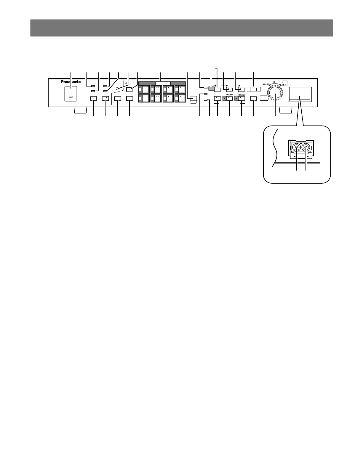
MAJOR OPERATING CONTROLS AND THEIR FUNCTIONS
■ Front View
OPERATE
ALARM
SUSPEND
RESET
HDD
FULL
ERROR
OSD
MULTISCREEN
SELECT
ZOOM
TIMER
DST
REMOTE
LOCK
SEQUENCE
ALARM
SERCH
STOP
PLAY MODE SELECT
SETUP
/ESC
PLAY
TIME&DATE
SEARCH
REC STOP
SPOT
MULTI
CAMERA SELECT
ALARM
RECALL
REC
PUSH— PAUSE
SET
Digital Disk Recorder WJ-HD220
1526374
8
q
w e
r u o !1 !5
tyi !0
!2
!3 !4 !8 !9
!7 @0
@2@1 @3!6 @4 @5
@6 @7
q Operate Indicator (OPERATE)
Lights up when the power of the WJ-HD220 Digital Disk
Recorder is turned on.
w Alarm Indicator (ALARM)
Blinks when an alarm condition exists. It changes to
steady light when the activated alarm is reset after the
auto-reset time has elapsed.
To turn the indicator off, press the ALARM RESET button.
e Alarm Suspension Indicator (SUSPEND)
Lights up when the alarm suspension mode is selected.
r Alarm Reset Button (RESET)
Pressing this button cancels an activated alarm, and
returns the system to the condition before the alarm
was activated.
t Timer Indicator (TIMER)
Lights up when the internal timer works after setting the
TIMER to INT (internal) in the menu setup. It blinks while
recording during the specified start and end time.
y Remote Indicator (REMOTE)
Lights up when the recorder is remotely controlled via
the serial port or 10BASE-T/100BASE-T port on the rear
panel.
u Lock Button (LOCK)
Holding down the button for 2 seconds will enable or
disable the button lock function. While locked, the buttons at the front panel are not operable and the LED in
the LOCK button lights up.
i Daylight Saving Time (DST)
The button is recessed inside the front panel opening.
Pressing this button shifts the internal clock to the summer time or vice versa.
o On Screen Display Button (OSD)
Toggles the "on screen display" (OSD) on and off. You
can eliminate OSD when it veils a portion on the monitor
you wish to observe. OSD includes the time and date,
alarm status, camera title, and recorder status. The status information is displayed only on the multiscreen
monitor.
!0 Monitor Selection Button (SPOT/MULTI)
Toggles the monitor selection between the spot monitor
and multiscreen monitor you wish to control.
When the spot monitor is selected, the LED in the button lights up.
!1 Sequence Button (SEQUENCE)
Runs the assigned sequence on the selected monitor
for the specified duration. Pressing this button pauses
the sequence, or restarts the paused sequence.
The LED in the button lights up when running, or blinks
when pausing.
!2 Camera Selection Buttons (CAMERA SELECT)
Pressing a button selects the input live image, or the
recorded image of the specified input. The LED in the
button indicates the status of the camera input as follows.
Green: The input displayed on the monitor is not being
recorded, but is a live or playback image.
Yellow: The input is displayed on the monitor, and is
recorded on the hard disk.
Page 8

8
Orange: The input is not displayed on the monitor, but
is recorded on the hard disk.
Blink Yellow: The input channel has an activated alarm
and is in alarm recording mode.
Blink Green: The input channel has an activated alarm
but it is not recorded.
These buttons are used for password input to release
the button lock function.
!3 Multiscreen Selection Button (MULTISCREEN
SELECT/ZOOM)
Selects the multiscreen pattern to be displayed on the
multiscreen monitor. The pattern changes every time
the button is pressed depending on the setup for
MULTI SEL MODE.
When ALL is selected:
Pattern 4A (comprising input 1, 2, 3, 4) → Pattern
4B (5, 6, 7, 8) → Pattern 9 (1-8) → Pattern 4A
When QUAD ONLY is selected:
Pattern 4A → Pattern 4B → Pattern 4A
Holding down this button for 2 seconds electronically
enlarges the specified area when a single picture is displayed on the multiscreen monitor.
!4 HDD Access Indicator (HDD)
Lights up when the HDD is accessed.
!5 FULL Indicator (FULL)
Lights up when the available disk space has dropped
below the percentage specified for HDD FULL and
when STOP is set for DISK END MODE.
!6 Error indicator (ERROR)
Blink Yellow: S.M.A.R.T. (Self-Monitoring Analysis and
Reporting Technology) reports that the usable lifetime of the HDD is nearing its end.
Blink Red: HDD error, HDD removed automatically, or
thermal error.
!7 Stop and Setup/Escape Button (STOP SETUP/ESC)
Pressing this button except in the menu setup or
recording will stop the playback.
Holding down this button for 2 seconds calls up setup
menus, or escapes from the setup.
In the setup menu, pressing this button will go one step
back to the previous selection.
!8 Playback Button (5PLAY)
Pressing this button starts the playback. The LED in the
button lights up while playing back, and it blinks while
pausing the playback or searching the record.
!9 Recording Button (8REC)
Pressing this button manually starts recording. The LED
in the button lights up during recording mode.
Recording starts when this button is pressed manually,
when the preset time for the internal timer comes, or
when an alarm sensor is activated.
@0 Recording Stop Button (REC STOP)
Pressing the button for two seconds stops recording.
Recording in any mode is stopped exclusively with this
button.
@1 to @4 are playback mode selection (PLAY MODE
SELECT) buttons.
@1 Alarm Search Button (ALARM SEARCH)
Pressing this button enables the JogDial to retrieve the
beginning image of the desired alarm record. Press the
[PLAY] button after searching the alarm record to play it
back.
@2 Step Playback & Down Button (
4
h/ h
5
C)
Pressing this button allows the JogDial to advance pictures field by field for minute searching.
In the menu setup, pressing this button moves the cursor downward.
@3 Skip Playback & Up Button ( / D)
Pressing this button allows the JogDial to skip some
picture fields in rough searching.
In the menu setup, pressing this button moves the cursor upward.
@4 Time and Date Search Button (TIME&DATE
SEARCH)
Pressing this button opens the time & date search window. Specify the time and date of the desired record
rotating and pressing the JogDial, then press the
[PLAY] button to start playback.
@5 JogDial (PUSH–
h
PAUSE /
4
h
/
h
5
SET ALARM RECALL)
When playing back at normal speed (PLAY):
Pressing the JogDial pauses or restarts playback.
When operating alarm search (ALARM SEARCH):
Rotating the JogDial will access the beginning
image of the next later or next older alarm record.
Holding down the JogDial for 2 seconds will jump to
the newest record at the disk end in forward playback, or to the oldest record in reverse playback.
When playing back in step mode (STEP):
Rotating the JogDial one click clockwise or counterclockwise will access the next later or next older
image field. A minute search for the desired field
can be made.
When playing back in skip mode (SKIP):
Rotating the JogDial changes the skip playback
speed and directions. The more turns you rotate the
JogDial, the faster the pictures will change. A rough
search for the desired field can be made.
Holding down the JogDial for 2 seconds will jump to
the newest record at the disk end in forward playback, or to the oldest record in reverse playback.
When pausing the playback:
Holding down the JogDial for 2 seconds will return
to the live image display, and the alarm list will
appear.
Page 9

9
While opening the time and date search window
(TIME&DATE SEARCH):
Pressing the JogDial moves the cursor to the next
position in the window.
Rotating the JogDial increases or decreases the
parameter.
After specifying the date and time, press the [PLAY]
button to start playback.
When operating alarm recall (ALARM RECALL):
Holding down the JogDial for two seconds will open
or close the alarm event log on the monitor.
Rotating the JogDial will scroll up or down the log
page.
After selecting an alarm event with the [D] or [C]
button, press the [PLAY] button to start playing
back the selected alarm record.
When operating setup menus:
Pressing the JogDial validates the selected parameter and moves the cursor to the next position.
Rotating the JogDial increases or decreases the
parameter.
@6 Audio Out
An RCA standard type jack supplies audio output signal that is identical to the AUDIO OUT terminal on the
rear panel.
@7 Video Out (VIDEO OUT)
An RCA standard type jack supplies a video output signal that is identical to the MULTI OUT terminal on the
rear panel.
Page 10

10
SIGNAL GND
POWER
DATA10/100BASE-TMODERS-232C
MULTI
SCREEN OUT
SPOT
OUT
1
1
ALARM/REMOTE
OFF
ON
2
2
3
3
4
4
5
5
6
6
7
7
8
8
OUT
VIDEO
OUT
AUDIO
IN
IN
#1 #3
#0 #2 #4 #6 #9 $0
#5 #7 #8
$1 $2 $3
$4
■ Rear View
#0 Audio Input Connector (AUDIO IN)
An RCA standard jack that accepts an unbalanced
–10 dBV, 10 kΩ line input audio signal supplied from an
external device.
#1 Audio Output Connector (AUDIO OUT)
An RCA standard jack that supplies an unbalanced
–10 dBV, 600 Ω line output audio signal to an external
device.
#2 Video Input Connector (VIDEO IN 1-8)
Connectors 1-4 allow direct connection of the PSD
cameras (video and commands multiplexed) while connectors 5-8 accept only normal video signals. A 75 Ω
termination is made unless the video output terminal is
connected.
#3 Video Output Connector (VIDEO OUT 1-8)
This BNC supplies a video signal looped through the
video input terminal.
Connectors 1-4 will output signals only when the
recorder is turned on.
#4 Spot Output Connector (SPOT OUT)
This BNC supplies a full-screen live image signal to the
spot monitor while recording or not recording. No playback or split image, setup menu, or OSD information is
supplied via this connector.
#5 Multiscreen Output Connector (MULTISCREEN OUT)
This BNC provides the multiscreen monitor with the following video.
• Live image: single spot, multi-split spot, single
sequence, quad-split sequence
• Playback image: single spot, multiscreen spot
• OSD information: camera title, time and date,
recorder status, alarm status
The menu setup windows are also provided via this
BNC.
#6 Alarm/Remote Port (ALARM/REMOTE)
This port accepts the alarm inputs 1 - 8, and remote
controls while supplying status outputs. See ALARM/
REMOTE Connection for details.
#7 RS232C Port (RS-232C)
This 9-pin port is used to communicate with the personal computer when controlling the recorder, or updating
the firmware installed in the recorder. See Serial Port
Connections for cable wiring, and RS-232C Communication Protocol.
#8 Mode Setup DIP Switch (MODE)
A 6-bit switch is used for such system setups as disk
formatting, PSD chain termination, and so forth. See DIP
Switch Setting for details.
#9 10Base-T/100Base-T (10/100BASE-T)
This port is used to exchange control data with Ethernet
via an Ethernet Hub.
$0 Data Port (DATA)
This port is used to communicate with external devices
compatible with the PSD (Panasonic Security Data) protocol based on RS485.
$1 Cooling Fan
Prevents the temperature of the recorder from rising. Do
not block the ventilation openings.
$2 Power Switch (POWER ON OFF)
This switch turns the power of the recorder on and off.
$3 Signal Ground Terminal (SIGNAL GND)
$4 Power Cord
Is connected to an AC outlet.
Page 11
11
INSTALLATION
● Warning
This installation should be made by qualified service personnel or system installers.
● Notes
Places to avoid
• Direct exposure to sunlight or near a source of heat such as a radiator.
• Very dirty and dusty places. Places subject to strong vibrations.
• Near a transformer, dimmer, video player, radio or monitor. These may cause humming noise, etc.
About mounting
• Do not block the ventilation openings or slots in the cover to prevent the appliance from overheating.
• Always keep the temperature in the rack within +45 °C (113 °F).
• Secure the rear of the appliance to the rack with additional mounting brackets (procured locally), if the rack is subject to
vibration.
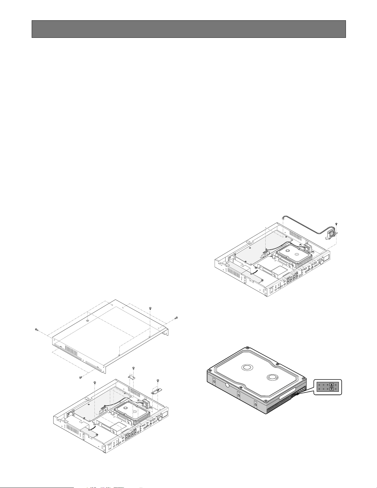
■ Installing the Optional HDD
(In case of the model installing a
single HDD)
There is an extension space inside the recorder to mount
the optional HDD unit, besides the one unit pre-installed
when shipped.
1. Unplug the power cord from the AC outlet.
2. Remove nine screws to detach the top cover.
You will see the additional HDD bracket adjacent to the
pre-installed HDD unit.
3. Remove six screws fastening the additional bracket.
4. Disconnect the fan cord connector on the main board.
Then remove the bracket with the fan from the chassis.
5. Prepare the optional HDD unit.
5-1 Attach the supplied serial number label and trans-
parent seal on the HDD unit surface as illustrated.
5-2 Set the jumper connectors as illustrated.
Notes:
• For pin connector settings, refer to the INSTRUCTIONS included with the HDD unit.
• Some optional HDD units to be added require setting change of the master HDD pin connector.
D
H
-
J
W
r
e
d
r
o
c
e
R
k
s
i
D
l
a
t
i
g
i
D
4
3
8
2
7
1
6
5
8
0
2
D
H
-
J
W
r
e
d
r
o
c
e
R
k
s
i
D
l
a
t
i
g
i
D
4
3
8
2
7
1
6
5
8
0
2
Page 12
12
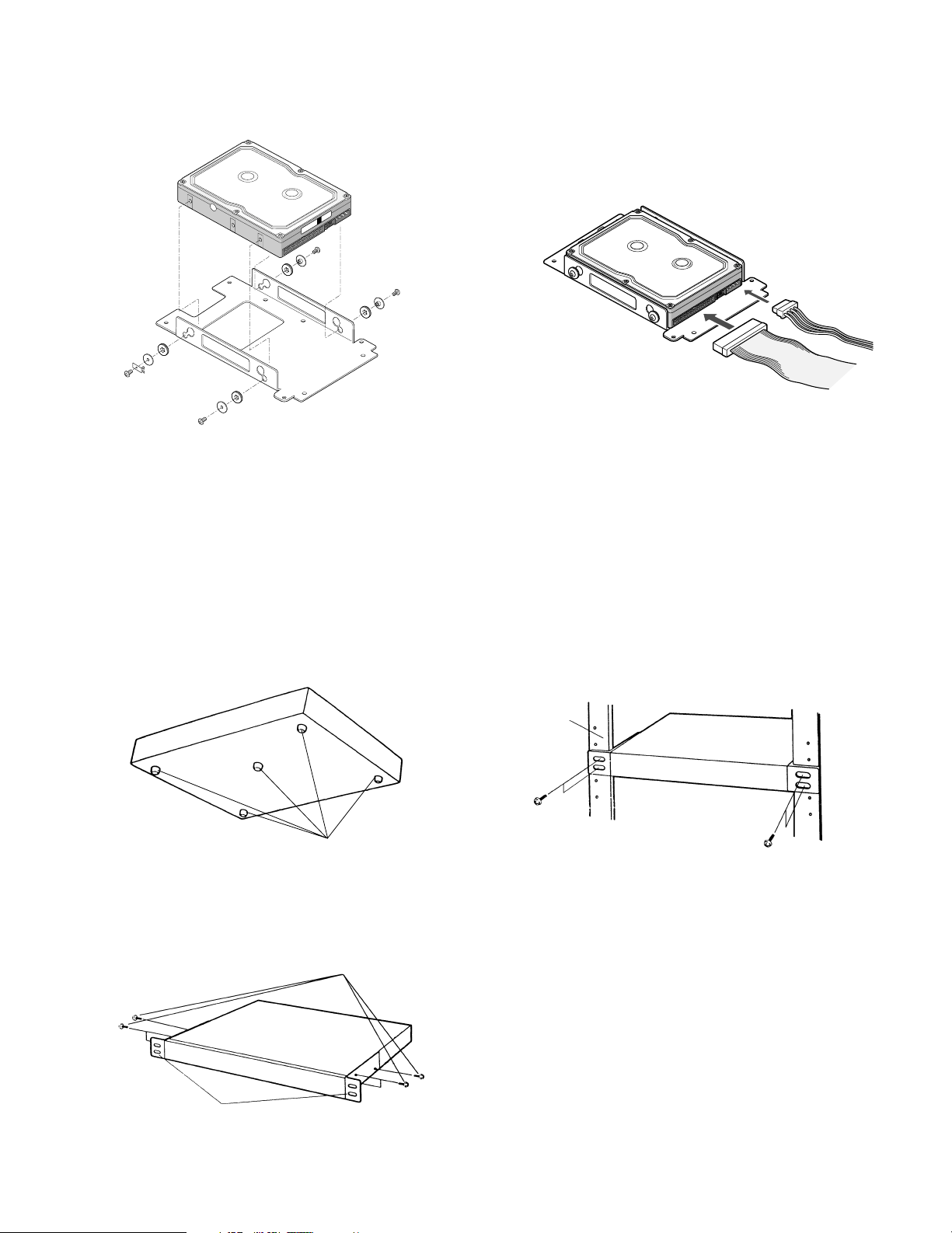
■ Mounting in the Rack
1. Remove the four rubber feet by removing the five
screws on the bottom of the unit.
2. Place the rack mounting brackets on both sides of the
unit and tighten with the six supplied screws (M3 x10).
3. Install the unit with the rack mounting brackets in the
rack by using four screws (not included).
Remove 5 rubber feet.
Six screws (Supplied)
Fix the rack mounting brackets.
Rack
6. Assemble the optional HDD unit onto the bracket using
the absorbers, sleeves, earth lug, and screws provided
with the recorder.
7. Place the HDD unit on the chassis, and fix it with six
screws.
8. Reinstall the fan cord and connector.
9. Connect the power cable and flat cable on the rear of
the HDD unit.
10. Fix the top cover to the recorder with nine screws.
AVSD
N
o
.
S
E
R
Page 13
13
CONNECTIONS & DIP SW SETTING
System Composition & Connections
Three system compositions are introduced depending on the camera type and other peripherals connected.
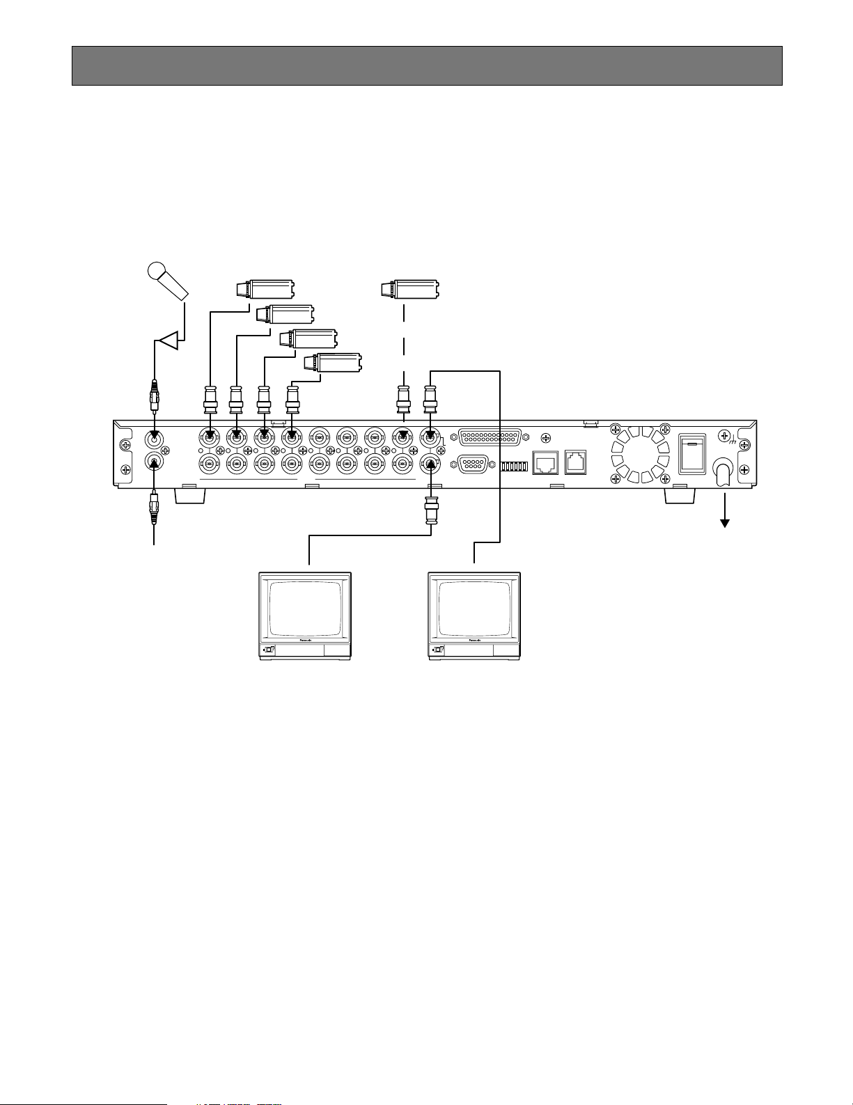
<Basic System>
Ordinary system-cameras are connected in combination with the multiscreen and spot monitors, microphone, and speakers.
Note: Be sure to set DATA to OFF in the CAMERA SYSTEM SETUP menu when connecting system cameras to VIDEO
IN connectors 1-4.
Microphone
Amplifier
IN
OUT
AUDIO
IN
OUT
Speakers via Amplifier
System Cameras System Cameras*
1
2
3
4
5
6
7
8
1
2
3
4
5
6
7
8
VIDEO
SCREEN OUT
MULTI
SPOT
OUT
ALARM/REMOTE
POWER
ON
SIGNAL GND
OFF
DATA10/100BASE-TMODERS-232C
AC 120 V 60 Hz
Multiscreen Monitor Spot Monitor
Page 14
14
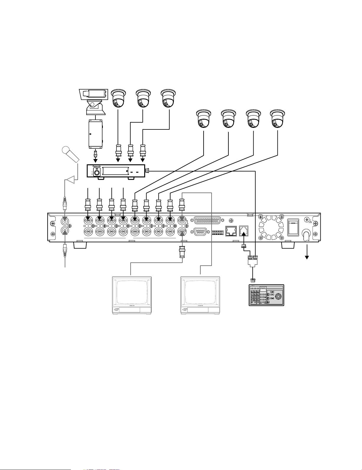
<PS•Data System>
Cameras equipped with data multiplex function are connected in combination with the system controllers and multiplex unit
compatible with PS
•
Data.
Note: Set DATA to ON in the CAMERA SYSTEM SETUP menu when connecting combination cameras to VIDEO IN 1-4.
SIGNAL GND
POWER
DATA10/100BASE-TMODERS-232C
MULTI
SCREEN OUT
SPOT
OUT
1
1
ALARM/REMOTE
OFF
ON
2
2
3
3
4
4
5
5
6
6
7
7
8
8
OUT
VIDEO
OUT
AUDIO
IN
IN
AC 120 V 60 Hz
Speakers via Amplifier
System Controller
System Controller
Compatible with PS-Data
Multiscreen Monitor Spot Monitor
POWER
ON
OFF
ALARM
Data Multiplex Unit WJ-MP204
ALARM
SUSPEND
Combination Cameras
Pan/Tilt Table
Receiver
Data Multiplex Unit
RS485 Cable
(WV-CA48)
Microphone
Amplifier
Combination Cameras
Page 15
15
SIGNAL GND
POWER
DATA10/100BASE-TMODERS-232C
MULTI
SCREEN OUT
SPOT
OUT
1
1
ALARM/REMOTE
OFF
ON
2
2
3
3
4
4
5
5
6
6
7
7
8
8
OUT
VIDEO
OUT
AUDIO
IN
IN
AC 120 V 60 Hz
POWER
ON
OFF
ALARM
Data Multiplex Unit WJ-MP204
ALARM
SUSPEND
Combination Cameras
Pan/Tilt Table
Receiver
Data Multiplex Unit
Hub/Router
PC (Internet Browser)
PC (Internet Browser)
RS485 Cable
(WV-CA48)
LAN Cable
(10Base-T/100Base-TX
Category 5)
LAN/Internet
Combination Cameras
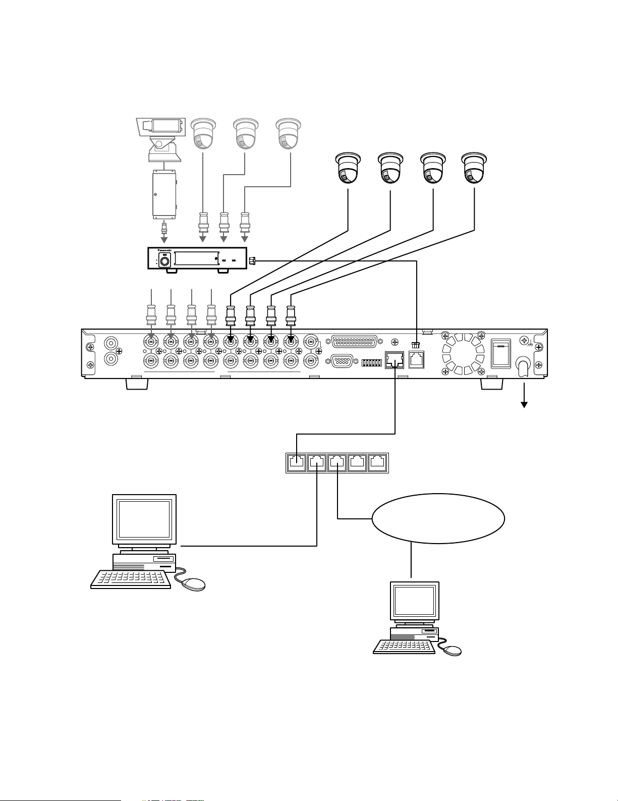
<Network System>
Personal computers can access the WJ-HD220 via the network.
Page 16
16
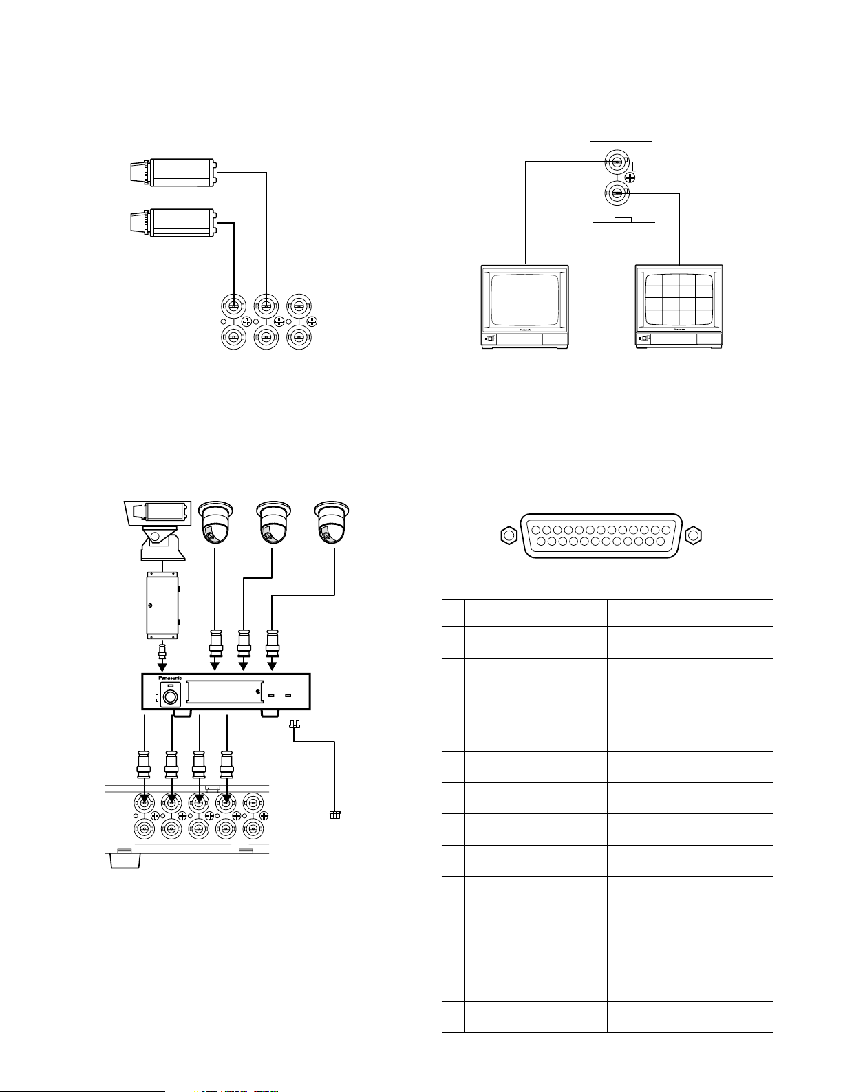
■ Connection with the Camera Site
● System Camera Connection
Connect system cameras to VIDEO IN 5-8.
● Data-multiplex Camera Connection
Connect combination cameras directly to VIDEO IN 1-4.
When connecting to VIDEO IN 5-8, use a Data Multiplex
Unit as shown below.
■ Connection with the Monitors
Connect the spot and multiscreen monitors.
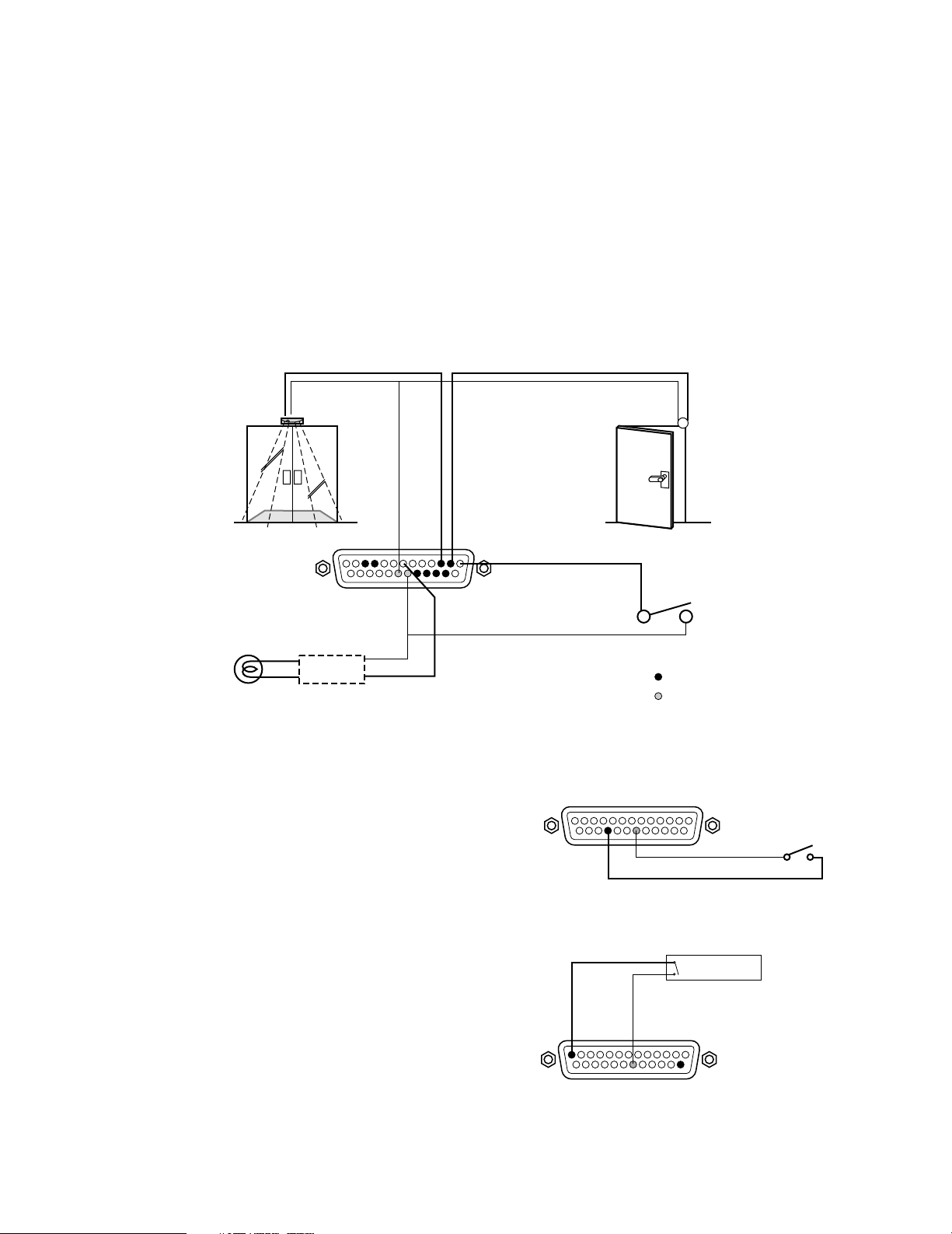
■ ALARM/REMOTE Connection
A 25-pin connector is used to accept and supply control
signals.
Pin
#
Designation
1
2
3
4
5
6
7
8
9
10
11
12
13
Alarm Reset In
Alarm In 1
Alarm In 2
Alarm Recovery Out *1
Alarm Recovery Out 2
Alarm Out 1
Alarm Out 2 *2
Disk End Out
Warning Out
Alarm In 3
Alarm In 4
REC Status Out
Time Adjust In
Pin
#
14
15
16
17
18
19
20
21
22
23
24
25
Designation
Time Adjust Out
Alarm In 5
Alarm In 6
Alarm In 7
Alarm In 8
Signal GND
Signal GND
Play Status Out
EXT REC MODE In
No Connection
Sequence In
Sequence Out
6
7
8
IN
6
7
8
OUT
Combination Cameras
Disk Recorder
WJ-HD220
SPOT
OUT
MULTI
SCREEN OUT
POWER
ON
OFF
Spot Monitor
POWER
ON
OFF
Multiscreen Monitor
13
1
Pan/Tilt Table
Receiver
OUT
25
ALARM/REMOTE
POWER
ON
OFF
ALARM
SUSPEND
ALARM
Data Multiplex Unit WJ-MP204
Data Multiplex
Unit
RS485 Cable
4
5
6
7
8
IN
8
VIDEO
4
5
6
7
DATA
14
Page 17
17
Notes:
• Input rating: Low-active, non-voltage normally open (N.O.) contact
• Output rating for pin #4 Alarm Recovery Out
*1
: High-active with a 200 Ω resistor pulled up to +5 V
• Output rating for pin #7 Alarm Out 2
*2
: High-active with a 4.7 kΩ resistor pulled up to +12 V
• Output rating for pin #6 Alarm Out 1: Low-active, maximum load capacity of +12 V 100 mA
• Output rating for other pins: Low-active, maximum load capacity of 24 V 100 mA , open-collector with a 4.7 kΩ resistor
pulled up to +5 V inside
• Pin #24 Sequence In receives a close contact input to advance the sequence one step. This input does not start a
sequence but forwards the presently running sequence by one step.
• Pin #25 Sequence Out supplies a negative pulse when the sequence running on the multiscreen monitor advances one
step.
● Alarm Connection
There are eight alarm inputs, while two outputs are provided with different driving capacity.
● External Recording Connection
The recording mode will change from the internal timer
mode to the external mode (EXT REC MODE) specified in
REC SETUP menu when the switch is turned on.
● Time Adjusting Connection
The internal timer is calibrated with this input.
Sensor
#3 Alarm In 2
Alarm Indicator
Relay *1
#7 Alarm Out 2 *2
*1: Use when the indicator exceeds over the drive capacity of the alarm out terminal.
*2: Connect to #6 Alarm Out 1 when using a low-active device.
Door Switch
#2 Alarm In 1
External
Alarm
Reset Switch
Alarm Input Terminals
Signal Ground Terminals
#22 External Recording Mode
Master Clock
Non-voltage N.O. contact
N.O.=Normally Open
#13 Time Adjust In
Page 18
18
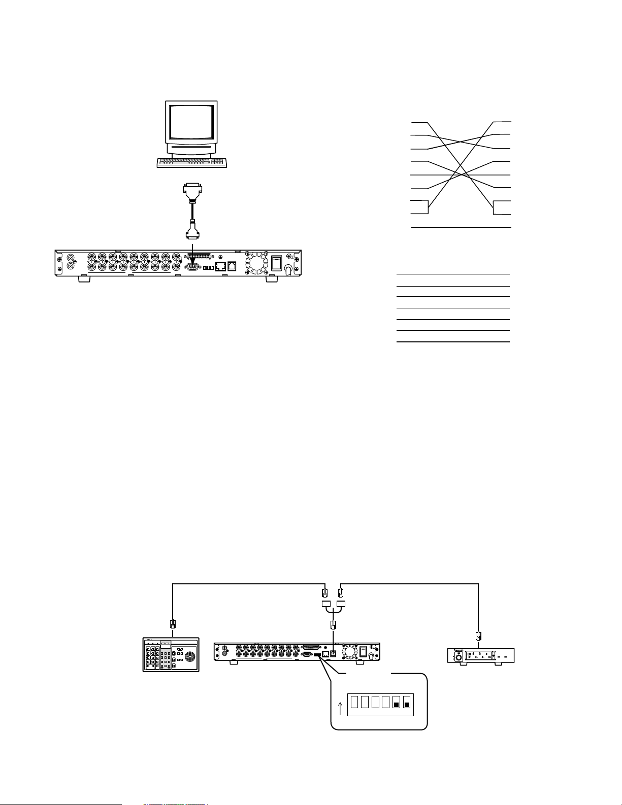
■ Serial Port Connections
● RS-232C Connection
A 9-pin connector is provided with the recorder to communicate with the PC via the RS-232C interface.
● PS•Data Connection
Note the following when connecting the recorder with PS•Data devices.
1. Place the recorder in the middle of the chain when the System Controller and other devices are connected.
2. Termination must be made at both ends of the chain.
Refer to the manual included with each device for termination.
See page 20, ■ DATA Port Termination for the recorder.
3. Protocol selection must be set to PS
•
DATA in the menu setup.
4. Use the optional RS-485 cable for connection.
Connection examples are shown.
<Case 1 > With System Controller and other devices
Personal Computer
D-sub9
or
D-sub25
D-sub9
IN
IN
OUT
AUDIO
VIDEO
1
SPOT
OUT
ALARM/REMOTE
1
22334455667788OUT
MULTI
SCREEN OUT
DATA10/100BASE-TMODERS-232C
POWER
ON
SIGNAL GND
OFF
Digital Disk Recorder
Note: Using a conversion cable may malfunction since
this RS-232C is incompatible with USB.
WJ-HD200
Frame
WJ-HD200
DB9
2 (RXD)
3 (TXD)
4 (ER)
5 (GND)
6 (DR)
7 (RTS)
8 (CTS)
DB9
1
2
3
4
5
6
7
8
Shield
PC
DB9
1
2
3
4
5
6
7
8
Frame
PC
DB25
2 (TXD)
3 (RXD)
6 (DR)
7 (GND)
20 (ER)
5 (CTS)
4 (RTS)
RS-485 Cable
POWER
ON
SIGNAL GND
OFF
1 2 3 4 5 6
UNIT
ALARM
0
1
9
POWER
2
8
3
7
SUSPEND SET UP
RESET
4
6
5
ON
OFF
ESCSET
1234
Data Multiplex Unit WJ-MP204
Data Multiplex Unit
Termination : ON
System Controller
System Controller
Termination : ON
RS-485 Cable
IN
IN
OUT
AUDIO
Disk Recorder
1
SPOT
OUT
ALARM/REMOTE
1
22334455667788OUT
VIDEO
SCREEN OUT
MULTI
DATA10/100BASE-TMODERS-232C
DIP Switch
(#5 : OFF, #6 : OFF)
ON
MODE
ALARM
SUSPEND
ALARM
Page 19
19
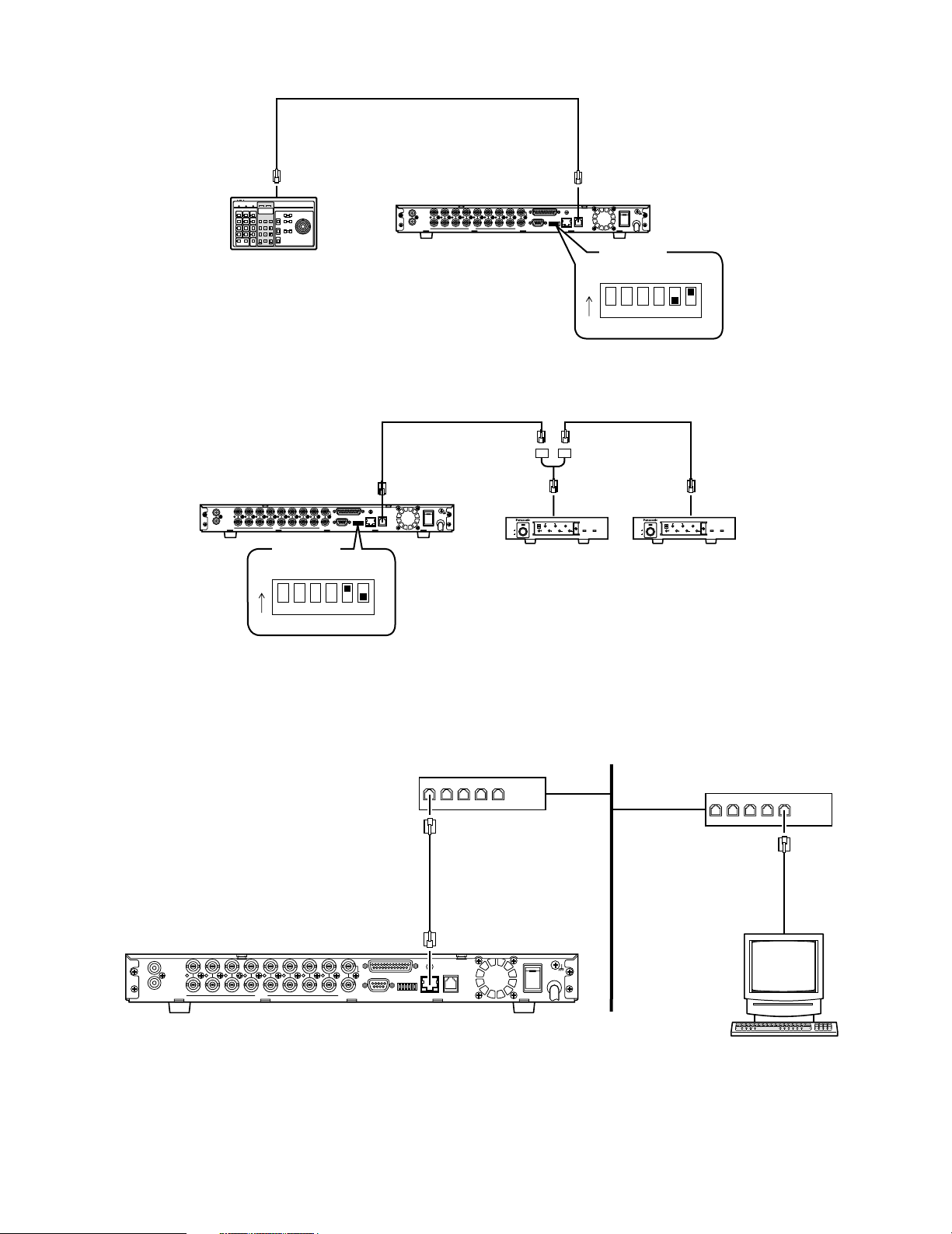
<Case 2> Exclusively with System Controller
<Case 3> With other system devices except System Controller
● 10/100BASE-T Port Connection
The PC controls the WJ-HD220 via Ethernet.
RS-485 Cable
System Controller
System Controller
IN
IN
OUT
AUDIO
Disk Recorder
Termination : ON
RS-485 Cable
Disk Recorder
IN
IN
OUT
AUDIO
1
SPOT
OUT
ALARM/REMOTE
1
22334455667788OUT
VIDEO
SCREEN OUT
MULTI
POWER
ON
SIGNAL GND
OFF
DATA10/100BASE-TMODERS-232C
DIP Switch
(#5 : ON, #6 : OFF)
ON
1 2 3 4 5 6
MODE
1
1
22334455667788OUT
VIDEO
POWER
ON
OFF
Data Multiplex Unit
Termination : OFF
SCREEN OUT
SPOT
OUT
MULTI
ALARM/REMOTE
UNIT
ALARM
0
1
9
2
8
3
7
RESET
SUSPEND SET UP
4
6
5
ESCSET
1234
POWER
ON
SIGNAL GND
OFF
DATA10/100BASE-TMODERS-232C
DIP Switch
(#5 : OFF, #6 : ON)
ON
1 2 3 4 5 6
MODE
RS-485 Cable
ALARM
SUSPEND
ALARM
Data Multiplex Unit WJ-MP204
UNIT
ALARM
0
1
9
POWER
2
8
3
7
4
6
5
ON
1234
OFF
RESET
SUSPEND SET UP
ESCSET
Data Multiplex Unit WJ-MP204
ALARM
SUSPEND
ALARM
Data Multiplex Unit
Termination : ON
10/100BASE-T Cable
(Locally Procured)
IN
IN
OUT
AUDIO
VIDEO
1
SPOT
OUT
ALARM/REMOTE
1
22334455667788OUT
MULTI
SCREEN OUT
Digital Disk Recorder
LAN
Hub
Hub
POWER
ON
SIGNAL GND
DATA10/100BASE-TMODERS-232C
OFF
Personal Computer
Page 20
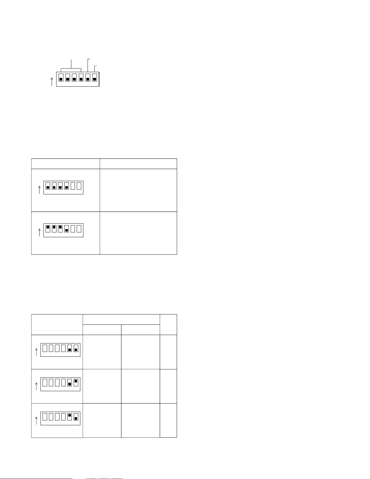
20
DIP Switch Setting
The 6-bit DIP switch is used as follows.
#1 through #4: System mode setup
#5 and #6: DATA port termination
■ System Mode
■ DATA Port Termination
Termination switch positions depend on the system composition.
Note: Use only the switch combinations shown in the table
above.
System Mode
Setup
ON
1 2 3 4 5 6
MODE
Switch Position Mode
Termination 1
Termination 2
ON
1 2 3 4 5 6
Normal operation mode
MODE
ON
1 2 3 4 5 6
Initializing HTML contents
MODE
Switch Position
ON
1 2 3 4 5 6
MODE
System Composition with:
System Controller
Yes
Other System
Devices
Yes
Note
<Case 1>
ON
1 2 3 4 5 6
ON
1 2 3 4 5 6
MODE
MODE
Yes
No
No
Yes
<Case 2>
<Case 3>
Page 21
21
SETUP PROCEDURES
■ Prior to Setup
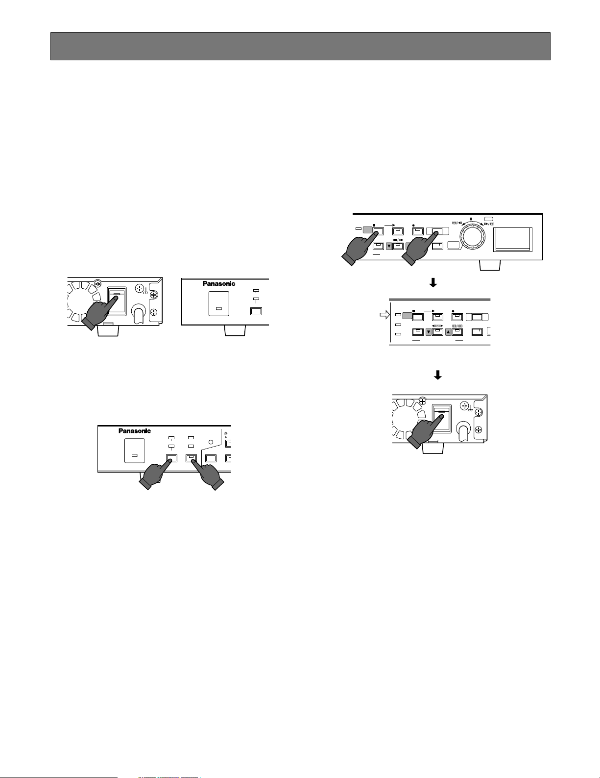
● Turning On the Power
1. Plug the power cord into the AC outlet.
2. Turn on the power switch on the rear panel. The operate LED lights up. An HDD check and a system check
will be carried out while displaying respective messages.
Power-on recording will start if TIMER has been set to
EXT in the SYSTEM SETUP menu.
3. Press the [REC STOP] button to stop power-on recording, if applicable.
4. Hold down the buttons of [LOCK] and [RESET] simultaneously to suspend alarm inputs. The SUSPEND indicator will light up. This will prevent your setting operations
from being interrupted by alarm inputs.
Note: Refer to Power-on Procedures in the Appendix
for details.
● Turning Off the Power
1. Press the [STOP] button when playing back, or [REC
STOP] button when recording. Confirm that the HDD
access indicator has turned off.
2. Turn off the power switch on the rear panel. The operate LED goes off.
Notes:
• Do not turn off the power while the HDD access
indicator is on.
• Do not leave the recorder turned off for a long time.
Supply AC power to the unit and turn it on to charge
up the backup battery.
L
E
E
P
U
POWER
ON
SIGNAL GND
OFF
OPERATE
TIMER DST
ALARM
REMOTE
OPERATE
SUSPEND
RESET
LOCK
OSD
SEQU
ALARM
SUSPEND
RESET
S
M
SET
HDD
SETUP
/ESC
FULL
ERROR
Confirm that
the HDD access
indicator is off.
STOP
ALARM
SERCH
PLAY MODE SELECT
PLAY
HDD
FULL
ERROR
SETUP
/ESC
ALARM
SERCH
REC
TIME&DATE
STOP
PLAY MODE SELECT
ON
OFF
PUSH— PAUSE
REC STOP
SEARCH
ALARM
RECALL
Digital Disk Recorder WJ-HD220
PLAY
POWER
REC
SIGNAL GND
REC STOP
TIME&DATE
SEARCH
A
R
Page 22
22
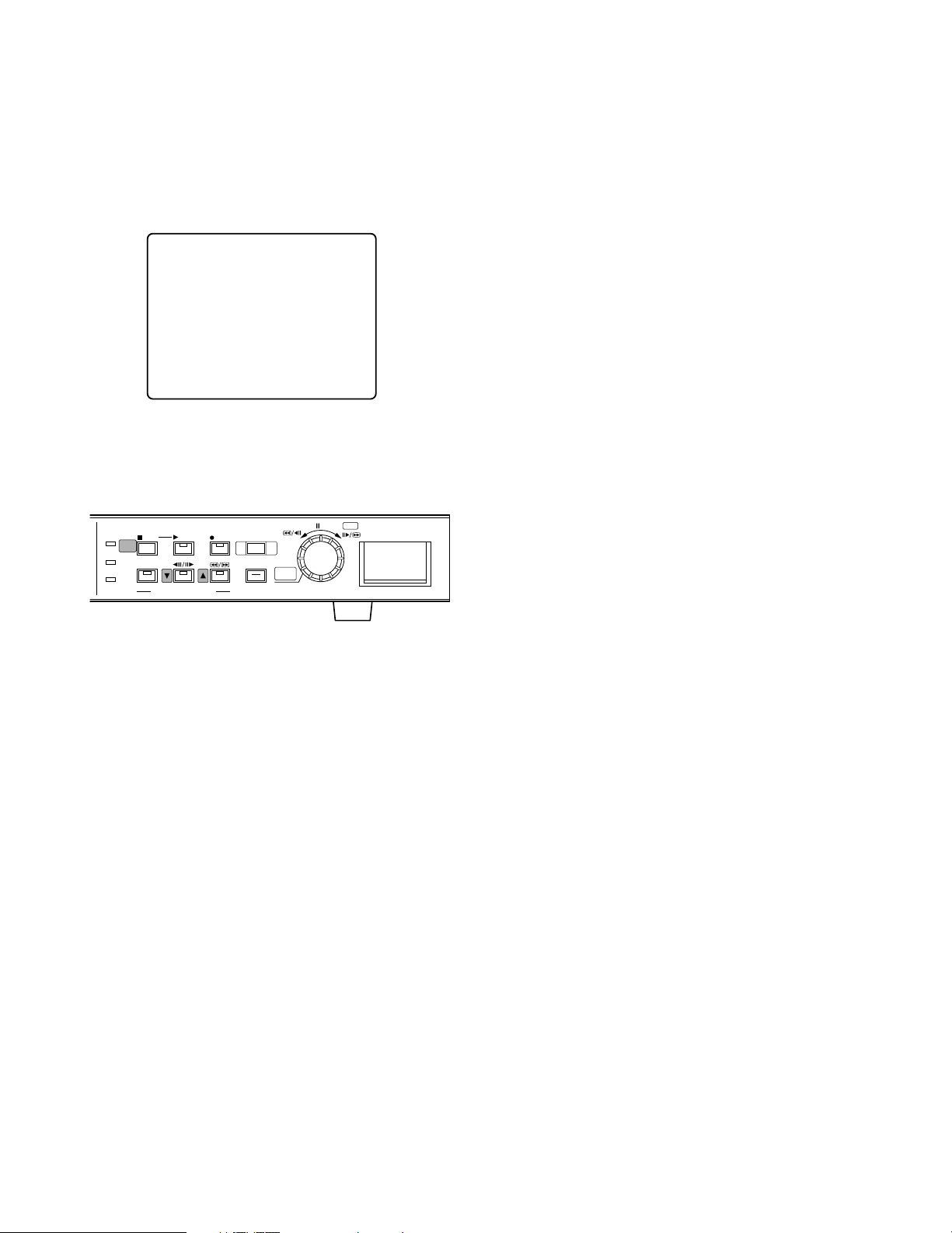
● Displaying WJ-HD220 (MAIN MENU)
1. Confirm that the camera and peripherals are connected
correctly and securely.
2. Turn on the power switches of all system components.
3. Hold down the [STOP] button for 2 seconds. The WJHD220 MAIN MENU appears.
● Buttons and Dials Used for Setup
[D up] button: Moves the cursor upwards in a menu, and
opens the previous menu page.
[C down] button: Moves the cursor downward in a menu,
and opens the next menu page.
JogDial (Counter-clockwise): Decreases the parameter
value.
JogDial (Clockwise): Increases the parameter value.
JogDial (Pressing) SET: Validates the selection, and
moves the cursor to the right. When the selected item
has a O return symbol, pressing this will open the next
lower layer menu for more minute settings
[STOP SETUP/ESC] button (Pressing): Moves the cursor
to the left, or returns to the previous menu.
[STOP SETUP/ESC] button (Holding down): Opens the
setup menu, or escapes from it and switches back to
normal operation.
● Closing WJ-HD220 (MAIN MENU)
1. Hold down the [STOP SETUP/ESC] button for 2 seconds.
The setup menu disappears, and normal operation will
be available.
Note: A blackout screen may appear for about 2 sec-
onds until the camera image is displayed if you
changed the settings and closed the setup menu.
WJ-HD220 MAIN MENU
TIMER OFF
REC SETUPO
EXT REC SETUPO
DISPLAY SETUPO
SYSTEM SETUPO
ALARM SETUPO
COMMUNICATION SETUPO
SWITCHER SETUPO
SYSTEM INFORMATIONO
LANGUAGE ENGLISH
HDD
FULL
ERROR
SETUP
/ESC
ALARM
SERCH
STOP
PLAY
PLAY MODE SELECT
REC
REC STOP
TIME&DATE
SEARCH
PUSH— PAUSE
ALARM
RECALL
Digital Disk Recorder WJ-HD220
SET
Page 23
23
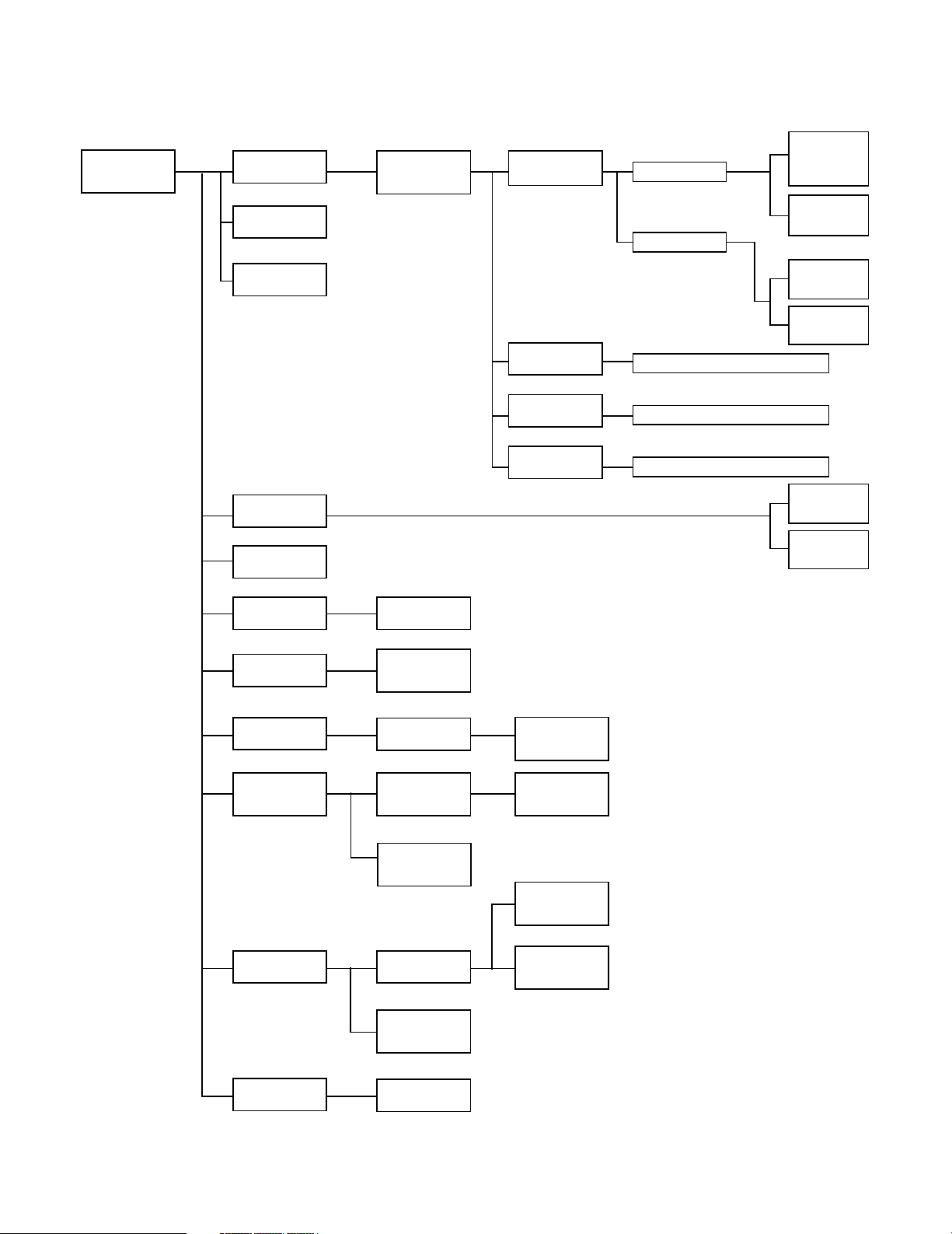
● Menu Tree
The figure shows the hierarchy of menu windows.
WJ-HD220
MAIN
MENU
TIME
ADJUST
SETUP
VMD
SETUP
SERIAL
PORT
SETUP
SEQUENCE
SETUP
CAMERA
VIEW
SETUP
SYSTEM
LOG
CAMERA
SYSTEM
SETUP
VMD
AREA
SETUP
MULTI
SEQ
SETUP
SPOT
SEQ
SETUP
SYSTEM
SETUP
CAMERA
TITLE
DISPLAY
SETUP
EXT REC
SETUP
REC
SETUP
TIMER
REC
(Assignment)
PROG1 SETUP
(Time Zone)
PROG2 SETUP
(Time Zone)
TRIGGER
ACTION
SETUP
1 - 1
CAM REC
SETUP
1 - 1
PROG1 NO. 1
PROG1 NO. 4
NO. 1 - NO. 4 (Same as PROG1)
PROG3 SETUP
(Time Zone)
NO. 1 - NO. 4 (Same as PROG1)
PROG4 SETUP
(Time Zone)
NO. 1 - NO. 4 (Same as PROG1)
TIMER
INT
ALARM
SETUP
COMMUNI-
CATION
SETUP
NETWORK
SETUP
SWITCHER
SETUP
SYSTEM
INFORMATION
~
~
TRIGGER
ACTION
1 - 4
CAM REC
SETUP
1 - 4
TRIGGER
ACTION
CAM REC
SETUP
TIMER
OFF
TIMER
EXT
Page 24
24
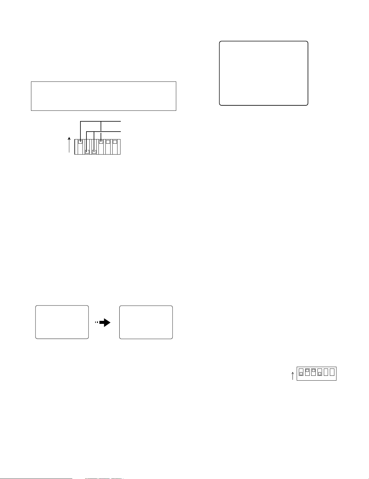
■ Initializing
You can initialize all disk contents including image data
and/or setup data.
● Initializing All Contents & Setup Data
Warning! The following are irrevocable procedures. We
strongly recommend that you copy important pictures from the hard disk.
1. Press the [REC STOP] button or [STOP] button to stop
recording or playback.
2. Turn off the power.
3. Set MODE switches #1 through 4 on the rear panel as
follows:
#1: ON
#2: OFF
#3: OFF
#4: ON
4. Turn on the power.
The disk contents and setup data are initialized.
Notes:
• This will take about 40 minutes.
• When finished, be sure to carry out step 5.
5. Turn off the power, and return the MODE switches to
the previous positions. Then turn on the recorder.
● Initializing Setup Data
1. Open the SYSTEM INFORMATION window, then move
the cursor to DEFAULT.
2. Press the JogDial to move the cursor to SET.
3. Press the JogDial.
4. Select YES with the JogDial.
YES: Initializing of setup data is enabled.
5. Press the JogDial.
SET DONE appears on the monitor after initializing.
6. Press the [SETUP/ESC] button.
The cursor moves to DEFAULT.
7. Hold down the [SETUP/ESC] button for 2 seconds to
quit the setup.
Notes:
• After closing the setup menu, the system may automatically restart if any parameter on the network
has been changed.
• The menu shown above is based on the assumption
that an optional HDD is installed in the recorder. As
shipped from the factory, the hour meter is set to 1
and the capacity to half.
● Initializing Settings for Network
Setup Menu
1. Stop recording or playback if
applicable, and turn off the
power.
2. Set the MODE switches as
shown in the figure.
3. Turn on the power. Wait for a few minutes until initializing is completed.
4. Return the MODE switches to the previous positions.
Then press the [STOP] button.
Note: These procedures reset the settings exclusively
for network setup menus: USER SETUP, HOST
SETUP, FTP SETUP, MAIL SETUP, and NETWORK
VIDEO SETUP.
MODE
ON
ON
OFF
123456
SYSTEM INFORMATION
HDD1 HOUR METER 10000H
HDD2 HOUR METER 10000H
HDD CAPACITY XXX.XXG
DEFAULT→ SET
SYSTEM VERSION X.XX
SYSTEM LOGO
→
NOW FORMATTING HDD
PLEASE TURN OFF MODE
FORMAT FINISHED
SW AND RESTART
ON
1 2 3 4 56
MODE
Page 25

25
■ Main Menu (WJ-HD220 MAIN
MENU)
The main menu is located at the top of the menu tree from
where every menu window starts.
1. Hold down the [SETUP/ESC] button for 2 seconds. The
main menu appears.
2. Select a setup menu you wish to program using the [D]
or [C] button, and press the [SET] (JogDial).
The selected setup menu opens. The following pages
will detail each setup menu.
■ Timer Recording Setup (TIMER
REC)
This menu assigns a timer to start recording by use of an
external timer or the internal timer. When the internal timer
(INT) is set, there are four programs assignable to the
weekly and/or daily schedule. Each program can contain
up to four events along with start and end time, and recording-mode. Alarm recording will be carried out when an
alarm operates within the scheduled time zone.
When the external timer (EXT) is set and the connected
timer switch turns on to supply power, the recorder will start
power-on recording.
1. Select a timer mode using the JogDial.
OFF: Does not use any timer, and manual recording is
available.
INT: Carries out internal timer recording according to
the program.
EXT: Carries out power-on recording.
2. Press the JogDial to validate the selection. When INT is
selected, the TIMER REC menu opens.
3. Move the cursor to the desired line using the [D] or
[C] button.
4. Select any parameter from PROG1 to PROG4 using the
JogDial, and press the JogDial. The PROG1-4 SETUP
menu opens.
● Program "1-4" Setup (PROG1-4
SETUP)
1. Select the event number with the [D] or [C] button,
and press the JogDial. The cursor moves to the START
position.
After this operation, the [D] and [C] buttons move the
cursor to the right and left.
2. Select a start time (START) using the JogDIal, and
press the [D] button to move to the next position.
Available START times: From 0:00 to 23:59 in the 24-
hour system.
3. Select an end time (END) in the same way as above
and press the [D] button to move the cursor to the
MODE position.
Available END times: From 0:00 to 24:00 in the 24-
hour system.
Notes: There are some restrictions on programming.
• An event, except the first event (NO 1), can be programmed only if the immediately preceding event
has been set up.
• The start time should be later than the end time of
the immediately preceding event.
• The end time should be later than the start time of
the event.
• An end time set at 24:00 will cancel all following
events.
• When you set both the start and end time of an
event to the same hour, the event will not be recorded.
• When planning to record all day long, set the start
time to 00:00 and the end time to 24:00 for the final
event.
• When planning to record through midnight:
Set 24:00 for the end time of the final event of the
day.
WJ-HD220 MAIN MENU
TIMER OFF
REC SETUPO
EXT REC SETUPO
DISPLAY SETUPO
SYSTEM SETUPO
ALARM SETUPO
COMMUNICATION SETUPO
SWITCHER SETUPO
SYSTEM INFORMATIONO
LANGUAGE ENGLISH
PROG1 SETUP
NO. START END MODE
1→ 8:00 12:20 SETO
→
13:00 15:00 SETO
2
3→ : :
4→ : :
TIMER REC
PROGRAM
SUNDAY PROG1O
MONDAY
TUESDAY
WEDNESDAY
THURSDAY
FRIDAY
SATURDAY
DAILY
Page 26

26
Set 00:00 for the start time of the initial event of the
next day.
• A combination camera will move to the preset position if an alarm arises and the position has been
assigned beforehand in TRIGGER ACTION SETUP
of the REC SETUP menu.
4. Press the JogDial while the cursor is on SETO to open
the event programming menu.
● Recording Mode Setup (PROG1-4
SETUP, NO. 1-4)
Parameters for internal timer recording are assigned to
each event (NO. 1-4) of the program (PROG 1-4) in this
menu. There are five recording modes available: super fine
(SF), fine (FQ), normal (NQ), long-time (EX) and optional
(SP). If combined with audio recording (-A), the number of
recording modes doubles. The remaining recording time
(shown as xx in the list below) is determined by the selected recording mode (10 options) and resolution (2 options)
in the SYSTEM SETUP menu.
In the SP mode, the field rate and picture quality are variable and can be selected at option in the range of 0.1 to 30
FPS with five quality level options respectively. After the
recording mode is selected, the available recording time is
determined and displayed.
Notes:
• By selecting a recording time, the recording rate (REC
RATE) and the recording quality (REC QUALITY) will be
automatically calculated and displayed. For details,
refer to the provided booklet "REC MODE TABLES for
WJ-HD220".
• Even if preset to 30 or 15 FPS, the actual recording rate
may drop to 7.5 FPS at worst while busy multi tasks
such as playback, remote-access playback, remoteaccess live image, FTP access, multi-split display, or
video motion detection are carried out simultaneously.
The status display will indicate "*PLAY" while playing
back the images recorded with a rate different from the
preset.
• Suffix "xxx" following "SP-" is specified in REC MODE
TABLE in the ADDENDUM attached to the manual.
1. Move the cursor to MODE, and press the JogDial. The
mode area will be highlighted.
2. Select a recording mode using the JogDial, and press
the Jogdial. Audio data will be recorded when a mode
with hyphen A is selected.
Available recording mode: SF, FQ, NQ, EX, SP, SF-A,
FQ-A, NQ-A, EX-A, and SP-A
3. When SP or SP-A is selected, specify a recording rate
(REC RATE) using the JogDial, and press the JogDial.
Available recording rates: From 0.1 to 30 FPS
4. When SP or SP-A is selected, specify a recording quality (REC QUALITY) using the JogDial, and press the
JogDial.
Available recording qualities: SUPER FINE, FINE,
NORMAL, EXTENDED
● Alarm Recording Mode Setup (ALM
REC MODE)
Alarm events arising within the time zone specified by the
program will start recording with the preset parameters.
Refer to "PROG NO. SETUP" described above in this menu
for operating procedures and available parameters, since
they are very similar.
● Pre-alarm Recording (PRE ALM REC)
Picture recording will start prior to the alarm activation at
the time specified by this setting.
1. Move the cursor to PRE ALARM REC with the [D] or
[C] button.
2. Select the desired pre-recording time with the JogDial,
and press the JogDial.
The default is 0S.
Available times (seconds): 0S, 1S, 2S, 3S, 4S, and 5S
N/A
Rec Mode Quality Audio Record Note
SF-xxxH Super Fine N/A
Field rate, quality
selected optionally
Field rate, quality
selected optionally
N/A
N/A
N/A
Available
Available
Available
Available
Fine
Normal
Long time
Optional setup
Super Fine
Fine
Normal
Long time
FQ-xxxH
NQ-xxxH
EX-xxxH
SP-xxxH
AvailableOptional setupSP-AxxxH
SF-AxxxH
FQ-AxxxH
NQ-AxxxH
EX-AxxxH
PROG1 NO.1 SETUP
REC MODE SF-24H
REC RATE 30FPS
REC QUALITY SUPER FINE
ALM REC MODE SF-24H
REC RATE 30FPS
REC QUALITY SUPER FINE
PRE ALM REC 0S
POST ALM REC 10S
DYNAMIC REC OFF
TRIGGER ACTION SETUPO
CAM REC SETUPO
Page 27

27
● Post-alarm Recording (POST ALM
REC)
This setting specifies the duration of alarm recording after
an alarm input. Functions active during alarm recording are
buzzer beeping, ALARM LED indication, "ALARM" status
display, and the ALARM OUT signal.
1. Move the cursor to POST ALARM REC with the [D] or
[C] button.
2. Select the desired duration with the JogDial.
The default value is 10 seconds.
The unit will revert to the previous status when the time
has elapsed.
Available times (seconds): 5, 10, 20, 30
Available times (minutes): 1, 1.5, 2, 3, 6
Continue: Recording continues until the [RESET] but-
ton is pressed, or the RESET IN signal is supplied to
the rear panel.
Manual: Recording continues for as long as the alarm
input is active, or at least for 10 seconds if the input
turns inactive earlier.
● Dynamic Recording (DYNAMIC REC)
This setting specifies the recording pattern on the disk
when one or more alarms operate.
1. Move the cursor to DYNAMIC REC with the [D] or [C]
button.
2. Select the parameter with the JogDial, and press the
JogDial.
The default is OFF.
ALM-MULTI: Alarmed channels are recorded with pri-
ority over others.
OFF: All channels are recorded with the same priority.
● Trigger Action Setup (TRIGGER
ACTION SETUP)
This setting specifies the two roles of alarm recording and
alarm control functions (Refer to page 47) in the post-alarm
sequence.
When combination cameras are connected to VIDEO IN 1-4
on the rear panel, you can select a preset position for cameras 1-4. The camera will move to the preset position when
an alarm other than VMD arises for the camera.
Notes:
• The preset position assignment on the TRIGGER
ACTION SETUP menu is not available for each PROG n
(1 - 4) SETUP menu, but available only for the REC
SETUP menu.
• You need to preset desired positions for the camera
prior to operation.
• VMD will not move the camera to the preset position.
1. Move the cursor to TRIGGER ACTION SETUPO, and
press the JogDial.
The TRIGGER ACTION SETUP menu opens.
2. Move the cursor to the channel.
3. Select a mode with the JogDial, and press the JogDial.
The default is REC&ALM.
OFF: Disables alarm recording or warning.
REC&ALM: Enables both alarm recording and warning.
REC: Enables alarm recording, but disables warning.
4. The cursor is at the PRESET column. Select a preset
parameter with the JogDial, and press the JogDial.
1-64: Moves the camera to the specified preset posi-
tion.
HOME: Moves the camera to the home position.
– –: Does not move the camera.
5. Repeat steps 2, 3 and 4 until all channels are set.
6. Press the [SETUP/ESC] button to return to the PROG1
SETUP, NO. 1 menu.
● Camera Recording Setup (CAM REC
SETUP)
This setting is provided for the purpose of saving disk
space. Setting allows each camera channel to be enrolled
in all recording modes or exclusively in alarm recording.
1. Move the cursor to CAM REC SETUP, and press the
[SET] button. The CAM REC SETUP menu opens.
2. Move the cursor to the camera channel with the [D] or
[C] button.
TRIGGER ACTION SETUP
CAM MODE PRESET
1→ REC&ALM ––
2→ REC&ALM ––
3→ REC&ALM ––
4→ REC&ALM ––
5→ REC&ALM
6→ REC&ALM
7→ REC&ALM
8→ REC&ALM
CAM REC SETUP
CAM MODE
1 REC
2 REC
3 REC
4 ALM-ONLY
5 REC
6 ALM-ONLY
7 REC
8 REC
Page 28

28
3. Select the parameter with the JogDial, and press the
JogDial.
The default is REC.
REC: The channel is recorded in alarm recording, timer
recording and manual recording mode.
ALM-ONLY: The channel is recorded only when the
alarm operates.
4. Repeat steps 2 and 3 until all channels are set.
5. Press the [SETUP/ESC] button to return to the PROG1
SETUP, NO. 1 menu.
■ Manual Recording Setup (REC
SETUP)
The WJ-HD220 will record image and audio data either with
or without timer restrictions. Manual recording is available
when OFF is selected for TIMER in WJ-HD220 MAIN MENU;
the timer schedule does not apply. Alarm recording will
also be carried out with parameters specified in this menu.
Refer to ● Recording Mode Setup PROG1-4 SETUP, NO. 14 for operating procedures and available parameters.
■ Externally Specified Recording Mode (EXT REC SETUP)
This setting allows changing the recording mode from the
ongoing one to an optional one specified here when turning
on the switch connected externally to the EXT REC terminal.
1. Move the cursor to EXT REC MODE with the [D] or [C]
button.
2. Select the desired mode with the JogDial, and press
the JogDial.
Refer to page 26 for the recording mode parameters.
3. Press the [SETUP/ESC] button to return to WJ-HD220
MAIN MENU.
■ Display Setup (DISPLAY SETUP)
You can program the display of information on the monitor,
such as clock, time and date, and so forth.
● Clock (CLOCK)
1. Press the JogDial (SET) to move the cursor to the
desired position.
2. Rotate the JogDial clockwise to increase the parameter,
or counter-clockwise to decrease. The positions indicate the year, month, day, hour, and minute respectively.
The default is "JAN 01. 04 0:00".
MMM DD. YY HH:MM
3. Press the JogDial (SET) to validate the selection.
4. Press the [D] or [C] button to select the next item, or
press the [SETUP/ESC] button to quit the display setup.
● Time & Date (TIME&DATE DISP.)
1. Select a display type with the JogDial.
The default is TYPE1 24H.
TYPE1 24H: Time and date are displayed in one line in
the 24-hour system.
TYPE1 12H: Time and date are displayed in one line in
the AM-PM system.
TYPE2 24H: Time and date are displayed in two lines in
the 24-hour system.
TYPE2 12H: Time and date are displayed in two lines in
the AM-PM system.
OFF: Does not display time and date.
DISPLAY SETUP
CLOCK→ JAN15.04 11:05
TIME&DATE DISP.TYPE1 24H
TIME&DATE POSI.R-LOWER
TIME&DATE EMB. OFF
STATUS DISP. ON
STATUS POSI. R-LOWER
HDD FULL 1%
REMOTE LED ON
HDD CHECK 0:00
CAMERA TITLEO
REC SETUP
REC MODE SF-24H
REC RATE 30FPS
REC QUALITY SUPER FINE
ALM REC MODE SF-24H
REC RATE 30FPS
REC QUALITY SUPER FINE
PRE ALM REC 0S
POST ALM REC 10S
DYNAMIC REC OFF
TRIGGER ACTION SETUPO
CAM REC SETUPO
JAN15.04 20:00:00
TYPE1
JAN15.04
20:00:00
TYPE2
Page 29

29
2. Press the JogDial (SET) to validate the selection.
3. Press the [D] or [C] button to select the next item, or
press the [SETUP/ESC] button to quit the display setup.
Notes:
• When a 9-split screen is displayed, only TYPE1 24H is
available.
• If “TIME&DATE EMB.” is set to ON and a display type
except OFF is selected, the type will be embedded in
the recorded data. If OFF is selected, TYPE1 24H will
be embedded in the data.
• The embedded time and date are displayed, but the
time and date display is hidden to avoid overlapping
them when both are set to ON and a single playback is
viewed.
● Time & Date Position (TIME&DATE
POSI.)
1. Select a display position with the JogDial.
The default is R-LOWER.
R-LOWER: Displays time & date in the lower right cor-
ner.
R-UPPER: Displays time & date in the upper right cor-
ner.
L-LOWER: Displays time & date in the lower left corner.
L-UPPER: Displays time & date in the upper left corner.
2. Press the JogDial (SET) to validate the selection.
3. Press the [D] or [C] button to select the next item, or
press the [SETUP/ESC] button to quit the display setup.
Notes:
• When the 9-split screen is displayed, the time and date
position is fixed to R-LOWER.
• The time and date display will be embedded in the
recorded data in the position specified here, if
TIME&DATE EMB. is set to ON.
● Time & Date Embedded (TIME&DATE
EMB.)
You can select either recording with time and date display
embedded or not. The display position and type in the
recorded data depend on the setups described above.
1. Select ON or OFF with the JogDial.
The default is OFF.
ON: Time & date display is embedded.
OFF: Time & date display is not embedded.
2. Press the JogDial (SET) to validate the selection.
3. Press the [D] or [C] button to select the next item, or
press the [SETUP/ESC] button to quit the display setup.
Notes:
• TYPE1 24H will be embedded in the recorded data if
TIME&DATE DISP is set to OFF and TIME&DATE EMB.
is set to ON.
• The embedded time and date are displayed, but the
time and date display is hidden to avoid overlapping
them when both are set to ON and a single playback is
viewed.
● Status Display (STATUS DISP.)
1. Select ON or OFF with the JogDial.
The default is ON.
ON: Status display is enabled.
OFF: Status display is disabled.
2. Press the JogDial (SET) to validate the selection.
3. Press the [D] or [C] button to select the next item, or
press the [SETUP/ESC] button to quit the display setup.
● Status Position (STATUS POSI.)
1. Select a display position with the JogDial.
The default is R-LOWER.
JAN15.04 11:15:00 JAN15.04 11:15:00
JAN15.04 11:15:00 JAN15.04 11:15:00
L-UPPER
L-LOWER
R-UPPER
R-LOWER
L-UPPER
PLAY PLAY
PLAY PLAY
L-LOWER
R-UPPER
R-LOWER
Page 30

● Remote LED (REMOTE LED)
The remote LED on the front panel will indicate or ignore
the remote controlled status of the recorder via the network.
1. Select either ON or OFF with the JogDial.
The default is OFF.
ON: REMOTE LED turns on when the network controls
the recorder.
OFF: REMOTE LED is deactivated.
2. Press the JogDial (SET) to validate the selection.
3. Press the [D] or [C] button to select the next item, or
press the [SETUP/ESC] button to quit the display setup.
● Disk Check (HDD CHECK)
S.M.A.R.T. (Self-Monitoring Analysis and Reporting
Technology) is activated or deactivated for HDD check.
1. Select either ON or OFF with the JogDial.
The default is OFF.
ON 0:00-23:00: The recorder checks the HDD at the
specified time every day.
OFF: Check is deactivated.
2. Press the JogDial (SET) to validate the selection.
3. Press the [D] or [C] button to select the next item, or
press the [SETUP/ESC] button to quit the display setup.
Note: Recording will resume after a one-second inter-
mission when HDD is checked.
30
R-LOWER: Displays status in the lower right corner.
R-UPPER: Displays status in the upper right corner.
L-LOWER: Displays status in the lower left corner
L-UPPER: Displays status in the upper left corner.
2. Press the JogDial (SET) to validate the selection.
3. Press the [D] or [C] button to select the next item, or
press the [SETUP/ESC] button to quit the display setup.
Note: When the 9-split screen is displayed, the status posi-
tion is fixed to R-LOWER.
● Disk Capacity Warning (HDD FULL)
The recorder monitors the disk capacity to warn the operator that the available capacity is nearing its end when STOP
is selected for DISK END MODE. There are two warning
levels. First, the FULL indicator on the front panel blinks
when the remaining capacity has reached the preset value.
Finally, the buzzer beeps when the disk is full, provided that
the DISK END BUZZER parameter in the SYSTEM SETUP is
set to ON. At the same time, the FULL indicator turns on.
1. Select the desired value with the JogDial.
The default is 1 %.
1% - 99%: The FULL indicator blinks when the remain-
ing capacity reaches the selected value.
2. Press the JogDial (SET) to validate the selection.
3. Press the [D] or [C] button to select the next item, or
press the [SETUP/ESC] button to quit the display setup.
DISPLAY SETUP
CLOCK→ JAN15.04 11:05
TIME&DATE DISP.TYPE1 24H
TIME&DATE POSI.R-LOWER
TIME&DATE EMB. OFF
STATUS DISP. ON
STATUS POSI. R-LOWER
HDD FULL 1%
REMOTE LED ON
HDD CHECK 0:00
CAMERA TITLEO
DISPLAY SETUP
CLOCK→ JAN15.04 11:05
TIME&DATE DISP.TYPE1 24H
TIME&DATE POSI.R-LOWER
TIME&DATE EMB. OFF
STATUS DISP. ON
STATUS POSI. R-LOWER
HDD FULL 1%
REMOTE LED ON
HDD CHECK 0:00
CAMERA TITLEO
DISPLAY SETUP
CLOCK→ JAN15.04 11:05
TIME&DATE DISP.TYPE1 24H
TIME&DATE POSI.R-LOWER
TIME&DATE EMB. OFF
STATUS DISP. ON
STATUS POSI. R-LOWER
HDD FULL 1%
REMOTE LED ON
HDD CHECK 0:00
CAMERA TITLEO
Page 31

31
● Camera Title (CAMERA TITLE)
Camera title and display position are specified for each
camera.
1. In the DISPLAY SETUP menu, move the cursor to CAMERA TITLEO, and press the JogDial to open the CAMERA TITLE menu.
2. Move the cursor to the camera you wish to program
using the [D] or [C] button.
3. Select either ON or OFF with the JogDial.
The default is ON for all cameras.
ON: Enables camera title display, title registration, and
position selection.
OFF: Disables the camera title functions.
4. Press the JogDial (SET) to validate the selection.
When ON is selected, go to the following steps. The
cursor moves to the title edit area.
When OFF is selected, return to step 2 above, or press
the [SETUP/ESC] button to escape from the CAMERA
TITLE menu.
5. <Editing>
5-1 Select a character for the digit with the JogDial.
Each title is identical to the camera number: 1, 2, 3,
and so forth as the default.
Available characters are as follows.
0 ~ 9 A ~ Z ! % &
( ) * – / : . ?
←→↑↓ •
5-2 Press the JogDial to validate the selection for the
digit.
The selected character is displayed on the digit,
and the cursor goes to the right digit.
5-3 Press the [C] button to move the cursor back to the
previous digit.
5-4 Repeat steps 5-1, 5-2 and 5-3 until all digits are
entered.
5-5 Press the JogDial when the cursor is on the right
end digit to validate the entered title. The cursor
moves to the POSI. column.
Note: A bullet (centered dot) stands for a space used
for deleting entered characters.
6. Select a display position with the JogDial.
The default setting for cameras 1, 2, 5, and 6 is RLOWER, for cameras 3, 4, 7, and 8 R-UPPER.
R-LOWER: Displays the camera title in the lower right
corner.
R-UPPER: Displays the camera title in the upper right
corner.
L-LOWER: Displays the camera title in the lower left
corner.
L-UPPER: Displays the camera title in the upper left
corner.
Note: When the 9-split screen is displayed, the camera title
position is fixed to R-LOWER.
7. Press the [D] or [C] button to select the next item, or
press the [SETUP/ESC] button to quit the display setup.
■ System Setup (SYSTEM SETUP)
There are two pages of the system setup. To turn a new
page, continue to move the cursor with the [D] or [C] button.
CAMERA TITLE
CAM TITLE POSI.
1 OFF
2 ON
3 ON
4 OFF
5 OFF
6 OFF
7 OFF
8 OFF
→
2•••• R-LOWER
→
3•••• L-LOWER
SYSTEM SETUP (1 OF 2)
PASSWORD LOCK OFF
ALL→ *****
OPERATION→ *****
KEYLOCK BUZZ ON
SKIP ALM-RECALL 1PAGE
SIMUL REC&PLAY ON
ALTER DETECT OFF
DISK END MODE CONTINUE
DISK END BUZZ ON
SYSTEM SETUP (2 OF 2)
PLAY PRIORITY LOCAL
TIME ADJUST SETUP
AUTO ERASING OFF
RESOLUTION→ NORMAL
HDD SAFETY MODE OFF
O
→
Page 32

32
● Password Lock Setup (PASSWORD
LOCK)
A five-digit password is entered to protect all settings,
recorded pictures, and operating status against erroneous
operation and tampering. Settings alone can be also protected from unauthorized access. While the LOCK indicator
on the front panel is on, a message "NOW KEY LOCKED!"
is displayed to warn unauthorized operators. If accessed in
this condition, the buzzer beeps.
1. Move the cursor to PASSWORD LOCK with the [D] or
[C] button.
2. Select either ON or OFF with the JogDial, and press the
JogDial.
The default is OFF.
ON: The buttons are password protected. The recorder
enters the button lock mode if neither a button nor
the JogDial is operated within a period of five minutes.
OFF: No password protection is applied.
3. Move the cursor to ALL→ or OPERATION→ with the
[D] or [C] button.
ALL: Allows both normal operations and setup opera-
tions.
OPERATION: Allows only normal operations. Setup
operations are not allowed.
4. Press the JogDial.
The preset password appears.
The default is "12345" for both ALL and OPERATION.
<New password setting>
5. Select a digit, rotating the JogDial.
6. Enter a number with the numeric button, and press the
JogDial.
The cursor moves one digit to the right.
7. Repeat steps 5 and 6 until all digits are entered.
8. Press the [SETUP/ESC] button to confirm the entered
password.
Go back to step 3 if you have not yet set the OPERATION password.
● Keylock Buzzer Setup (KEYLOCK
BUZZ)
1. Move the cursor to KEYLOCK BUZZ with the [D] or [C]
button.
2. Select either ON or OFF with the JogDial, and press the
JogDial.
The default is ON.
ON: Buzzer beeps when unauthorized access takes
place.
OFF: Buzzer does not sound.
● Skip Alarm Recall Setup
(SKIP ALARM RECALL)
Alarm log pages are recalled on the monitor when the
JogDial is pressed for 2 seconds. When searching in the
log, you may need to skip pages. The page will skip the
specified number forward or backward from the displayed
page when rotating the JogDial.
1. Move the cursor to SKIP ALM RECALL with the [D] or
[C] button, and press the JogDial.
2. Select the number of skip pages with the JogDial, and
press the JogDial.
The default is 1 page.
Available skip pages: 1, 5, 10, 20, 50 pages
E
ALARM
TIMER DST
SUSPEND
OPERATE
SYSTEM SETUP (1 OF 2)
PASSWORD LOCK OFF
ALL→ *****
OPERATION→ *****
KEYLOCK BUZZ ON
SKIP ALM-RECALL 1PAGE
SIMUL REC&PLAY ON
ALTER DETECT OFF
DISK END MODE CONTINUE
DISK END BUZZ ON
RESET
REMOTE
LOCK
OSD
S
SYSTEM SETUP (1 OF 2)
PASSWORD LOCK OFF
ALL→ *****
OPERATION→ *****
KEYLOCK BUZZ ON
SKIP ALM-RECALL 1PAGE
SIMUL REC&PLAY ON
ALTER DETECT OFF
DISK END MODE CONTINUE
DISK END BUZZ ON
SYSTEM SETUP (1 OF 2)
PASSWORD LOCK OFF
→
ALL
OPERATION
KEYLOCK BUZZ ON
SKIP ALM-RECALL 1PAGE
SIMUL REC&PLAY ON
ALTER DETECT OFF
DISK END MODE CONTINUE
DISK END BUZZ ON
*****
→
*****
Page 33

33
● Simultaneous Recording & Playback
(SIMUL REC&PLAY)
This setting specifies whether to allow simultaneous playback and recording.
1. Move the cursor to SIMUL REC&PLAY with the [D] or
[C] button.
2. Select on or off with the JogDial, and press the JogDial.
The default is ON.
ON: Allows simultaneous recording and playback
including remote-access playback and FTP access.
The default recording rate is 15 FPS, and the highest rate is 30 FPS.
OFF: Places priority on recording triggered by pressing
the REC button or by an alarm input. Playback
including remote-access playback and FTP access
will be interrupted if recording starts. The default
recording rate is 15 FPS, and the highest rate is 30
FPS.
Notes:
• A 30 FPS recording rate will decrease to 15 FPS
when playback, remote-access playback, or FTP
access is carried out simultaneously with recording.
• Simultaneous playback will pause prior to a time
space depending on the recording rate when the
playback area on the disk nears the recording area.
This is to avoid the access collision caused by the
simultaneous recording and playback in an area on
the disk.
0.1 FPS: 20 minutes maximum
1 FPS: 2 minutes maximum
7.5 FPS: 15 seconds maximum
15 FPS: 7 seconds maximum
• Even if preset to 30 or 15 FPS, the actual recording
rate may drop to 7.5 FPS at worst while busy multitasks such as playback, remote-access playback,
remote-access live image, FTP access, multi-split
display, or video motion detection are carried out
simultaneously. The status display will indicate
"*→PLAY" while playing back the images recorded
with a rate different from the preset.
● Alteration Detection Setup
(ALTER DETECT)
You can enable or disable the recorder to add alterationdetection signals in the JPEG data supplied to the network.
The default is OFF.
1. Move the cursor to ALTER DETECT.
2. Select ON or OFF with the JogDial and press the
JogDial.
ON: Detects alterations.
OFF: Does not detect.
Notes:
• When set to ON, the data transmission rate on the network will slow down.
• Ask your dealer whether alterations are found in the
image data distributed via the network if necessary.
● Disk End Mode Setup
(DISK END MODE)
The menu offers the following options at the point where the
available recording space on the disk is used up: [STOP],
[CONTINUE]
1. Move the cursor to DISK END MODE with the [D] or
[C] button.
2. Select the desired mode with the JogDial, and press
the JogDial.
The default is CONTINUE.
STOP: Stops recording until a new mode other than
STOP is selected.
CONTINUE: Old data is automatically overwritten from
the disk start.
Note: Remaining capacity will be displayed on the monitor
by turning the JogDial counter-clockwise in recording
mode when STOP is selected.
DISK ENDDISK START
[STOP]
Waiting for a new entry
Restart
REC
[CONTINUE]
[Default]
SYSTEM SETUP (1 OF 2)
PASSWORD LOCK OFF
ALL→ *****
OPERATION→ *****
KEYLOCK BUZZ OFF
SKIP ALM-RECALL 1PAGE
SIMUL REC&PLAY ON
ALTER DETECT OFF
DISK END MODE CONTINUE
DISK END BUZZ ON
Overwritten automatically
Stop
REC
DISK ENDDISK START
DISK ENDDISK START
DISK ENDDISK START
Page 34

34
● Disk End Buzzer (DISK END BUZZ)
The buzzer can be set up to beep at the point where the
disk is full (remaining space 0 %). The setting is available
only when STOP is set for DISK END MODE.
1. Move the cursor to DISK END BUZZ with the [D] or [C]
button.
2. Rotate the JogDial to select the desired parameter.
The default is ON.
ON: Enables the buzzer beep at the disk end (remain-
ing space 0 %).
OFF: Disables the buzzer beep.
● Play Priority Setup (PLAY PRIORITY)
This setting places priority on a specific access point for
playing back the image data when access collisions take
place.
1. Move the cursor to PLAY PRIORITY.
2. Select an access point with the JogDial and press the
JogDial.
LOCAL: Places priority on front panel operations.
NET PLAY: Places priority on network access.
FTP GET: Places priority on access to the FTP.
NONE: The latest operation has priority over others.
● Time Adjust Setup
(TIME ADJUSTING)
IN and OUT terminals for a calibration signal are provided
on the rear panel. The master unit supplies the calibration
signal to the slave units once at the specified hour everyday. The slave unit accepts the signal through the IN terminal, and corrects its internal timer to the hour as far as the
clock deviates within 15 minutes after or before the hour.
This is convenient for synchronizing the internal clock with
other connected devices.
1. Move the cursor to TIME ADJUST SETUPO in the SYSTEM SETUP with the [D] or [C] button, and press the
JogDial. The TIME ADJUST SETUP menu appears.
2. Select either MASTER or SLAVE with the JogDial, and
press the JogDial.
The default is SLAVE.
MASTER: The recorder supplies the calibration OUT
signal to the slave units.
SLAVE: The internal timer of the recorder is supplied
the calibration signal from the master.
3. Select the hour with the JogDial, and press the JogDial.
The hours: From 00:00 to 23:00
Note: You need not set the hour when SLAVE is select-
ed.
4. Press the [SETUP/ESC] button to go back to the SYSTEM SETUP menu.
● Auto Erasing Setup
(AUTO ERASING)
The redundant records on the disk can be erased every
day at 24:00 midnight. The number of days specified by
this setting stand for the number of days the records will be
protected from the present, while the records older than
that will be erased.
1. Move the cursor to AUTO ERASING with the [D] or [C]
button.
2. Select the desired number of days with the JogDial,
and press the JogDial.
OFF: Auto erasing is not applied.
1 DAY: Only today’s records from 00:00 onward are
protected. Records before 24:00 yesterday are
erased.
2 to 10DAYS: Records before the specified number of
days are erased.
14, 30, 45, 60, 90, 120, 150, 180DAYS: Same as
above.
SYSTEM SETUP (2 OF 2)
PLAY PRIORITY LOCAL
TIME ADJUST SETUPO
AUTO ERASING OFF
RESOLUTION→ NORMAL
HDD SAFETY MODE OFF
→
TIME ADJUST SETUP
TIME ADJUSTING SLAVE
SET TIME→ 9:00
Page 35

Notes:
• The number of days includes today as 1 day, therefore 2DAYS covers today and yesterday.
• Auto erasing is implemented at 24:00 midnight.
Playback will stop once when the time reaches
24:00, then will restart with a different portion based
on the renewed day count.
● Resolution (RESOLUTION)
Notes:
• We recommend that you perform this setup before
starting to operate the system. Changing the resolution
is an irrevocable procedure that results in the erasure of
all data previously recorded.
• When a new resolution is selected, the screen MAIN
MENU changes to a camera image. The recorder then
reboots with the new resolution applied.
1. Move the cursor to RESOLUTION and press the
JogDIal.
2. A password prompt is displayed. Enter a registered
password using CAM SEL buttons 1-8.
3. If the correct password is entered, the prompt screen
returns to the previous menu and resolution selection
becomes possible.
4. Rotate the JogDial to select a resolution and press the
JogDial.
The default is NORMAL.
NORMAL: Normal resolution
SIF: Source Image Format (lower than NORMAL)
5. Confirmation prompt is displayed.
35
6. If you do not need to change the resolution, press the
[SETUP/ESC] button. The menu will return to step 1
above.
7. If you intend to change it, rotate the JogDial to select
YES and press the JogDial.
The recorded data will be erased while "NOW ERASING" is displayed for a few seconds.
SYSTEM SETUP (2 OF 2)
PASSWORD
SYSTEM SETUP (2 OF 2)
********WARNING*********
ALL OF THE DATA
IN THE DISK
IS GOING TO BE ERASED.
- -----
/
ERASE?
-
NO
Page 36

36
● HDD Safety Mode (HDD SAFETY
MODE)
A hard disk drive can be damaged if it is moved and
shocked while its motor is revolving. This menu is provided
for HDD protection purposes and enables you to stop the
motors from starting even when the recorder is being powered. Use this when you cannot switch off the recorder and
you have to mount or dismount the units.
1. Move the cursor to HDD SAFETY MODE.
2. Select ON or OFF with the JogDial and press the
JogDial.
The default setting is OFF.
ON: Stops the HDD motors.
OFF: Keeps HDD motors revolving.
3. When you select ON, hold down the [SETUP/ESC] button for 2 seconds.
The recorder closes the setup menu and enters powerup procedures.
4. A message "DO NOT MOVE HDD" appears when
power-up procedures are completed.
Wait for about 30 seconds while the green indicators in
the numeric buttons 1-8 on the front panel turn on and
off every 2 seconds.
5. A message "ALL HDD MOTORS STOPPED" appears.
The indicators 1-8 light up in green for two seconds and
in amber for two seconds. Now you can move the units.
6. After you mount the units in the rack, move the cursor to
ON. Select OFF with the JogDial and press the JogDial.
OFF: Escapes from the menu and restarts power-up
procedures.
A message "SET DONE!" appears on the screen and
the recorder enters normal operation when power-up
procedures are completed.
Note: While HDD motors are stopped, the following
inputs will be disabled.
• Input events for recording: button operation, VMD
and lapse of preset record start time
• Inputs to ALARM/REMOTE port: alarm inputs
• Hour meter increment
*** HDD SAFETY MODE ***
DO NOT MOVE HDD!
WAIT UNTIL ALL
HDD MOTORS STOP.
–STILL IN PROCESS
FOR STOP–
*** HDD SAFETY MODE ***
ALL HDD MOTORS STOPPED.
NOW YOU CAN MOVE UNIT.
SELECT OFF AND PUSH JOG
TO RESTART.
HDD SAFETY MODE ON
Page 37

37
■ Alarm Setup (ALARM SETUP)
The digital disk recorder accepts alarm signals supplied
from connected devices such as sensors or camera site
equipment. The recorder itself also generates an alarm signal when the preset motion detection is activated. Any
alarm signal starts recording with the preset recording
mode, field rate, and picture quality specified in the REC
MODE menu described earlier. Alarm recording stops
when the preset time has elapsed, the alarm [RESET] button on the front panel is pressed, or the ALARM RESET IN
signal is supplied from the connected device. The recorder
outputs an alarm recovery signal from the rear panel.
● Alarm Buzzer (ALARM BUZZ)
Enables or disables buzzer beeping when an alarm operates.
1. Move the cursor to ALARM BUZZ with the [D] or [C]
button.
2. Rotate the JogDial to select ON or OFF.
The default is ON.
ON: Buzzer beeps while alarm is active.
OFF: Buzzer does not beep.
● Video Loss (VIDEO LOSS)
Enables or disables video loss detection.
1. Move the cursor to VIDEO LOSS with the [D] or [C]
button.
2. Rotate the JogDial to select ON or OFF.
The default is ON.
ON: Enables the recorder to detect video loss.
OFF: Ignores video loss.
● Monitor Mode (MONITOR MODE)
This setting specifies whether to allow the display on the
multiscreen monitor and spot monitor to change from the
currently displayed picture to the alarmed channel when an
alarm operates.
1. Move the cursor to MULTI OUT or SPOT OUT with the
[D] or [C] button.
2. Select the parameter with the JogDial, and press the
JogDial.
The default is SPOT.
SPOT: Switches to the picture of the alarmed channel.
OFF: Retains the previous display mode.
● Video Motion Detection
(VMD SETUP)
A VMD or Video Motion Detector senses changes in the
video signals within a preset area and supplies alarm output. When a change is detected, the recorder starts recording. The detection sensitivity and area are selected on this
menu.
1. Move the cursor to VMD SETUPO with the [D] or [C]
button, and press the JogDial. The VMD SETUP window
opens.
2. Move the cursor to the desired line.
3. Rotate the JogDial to select the desired parameter, and
press the JogDial.
The default is OFF.
LOW: Low sensitivity
MID: Medium sensitivity
HIGH: High sensitivity
OFF: Motion detection is disabled.
The area setup window appears with an asterisk when
other than OFF is selected. The asterisk represents the
upper-left or bottom-right of the detection area. The
division lines are not actually displayed on the monitor.
ALARM SETUP
ALARM BUZZ ON
VIDEO LOSS ON
MONITOR MODE
MULTI OUT SPOT
SPOT OUT SPOT
VMD SETUPO
VMD SETUP
CAM SENS
1 OFF
2 LOWO
3 MIDO
4 HIGHO
5 OFF
6 OFF
7 OFF
8 OFF
Page 38

38
Notes:
• Areas adjacent to the time and date display will be
excluded from VMD when TIME&DATE EMB is set
to ON. Set it to OFF when you need to include these
areas.
• VMD should be used when the input to the unit is
from an ordinary camera. Select [OFF] to avoid useless VMD when a video multiplexer or combination
camera supplies the input to the unit.
• Set ALARM SUSPEND to ON when you do not want
VMD to be activated during the VMD setup.
• There may be cases where VMD does not sufficiently detect changes, since it detects the
changes in luminance.
• The detection area may include areas slightly outside the border.
• The buzzer will beep if detection takes place during
the area setup.
4. Set the upper-left end of the detection area. Move the
asterisk to the right or left with the JogDial, and up or
down by pressing the [D] or [C] button.
5. Press the JogDial to enter the upper-left end of the
detection area. The asterisk position is highlighted.
6. Set the bottom-right end of the detection area similar to
steps 3 and 4 above.
7. Press the JogDial. The area is highlighted.
Up to 4 areas can be selected. These may partially
overlap. Repeat steps 3 to 6 to select more areas. To
deselect an area, move the cursor to the upper-left end
of the area, and press the JogDial.
■ Communication Setup
(COMMUNICATION SETUP)
Communication parameters are set to match those of the
connected devices and the system configuration. The serial
port setup and network setup are made.
■ Serial Port Setup
(SERIAL PORT SETUP)
The SERIAL PORT SETUP menu appears when it is selected in the COMMUNICATION SETUP menu.
Note: Parameters marked with * on the following pages are
default settings applicable to RS-232C.
● Protocol (PROTOCOL)
1. Move the cursor to PROTOCOL with the [D] or [C] button.
2. Select a suitable protocol with the JogDial, and press
the JogDial.
The default is PS
•
DATA.
q
e
*
CAM1
w
r
COMMUNICATION SETUP
SERIAL PORT SETUPO
NETWORK SETUPO
REW/FF
/
STEP
/
PUSH • PAUSE
/
SET
/
SERIAL PORT SETUP
PROTOCOL PS.DATA
BAUD RATE 9600
DATA BIT 8
PARITY CHECK NONE
STOP BIT 1
WAIT TIME OFF
CTL-UNIT ADDR 1
SYS-UNIT ADDR 1
ALARM DATA 1S
CAMERA SYSTEM SETUPO
Page 39

39
PS•DATA: Select when the communication chain uses
the PS
•
DATA protocol.
This selection enables the DATA terminal on the
rear panel for communication.
RS-232C: Select when a protocol other than PS
•
DATA
is used.
This selection enables the RS-232C terminal on the
rear panel for communication.
Note: Parallel use of the DATA and RS-232C terminals
is not possible.
● Baud Rate (BAUD RATE)
1. Move the cursor to BAUD RATE with the [D] or [C] button.
2. Select the rate with the JogDial, and press the JogDial.
The default value is 9600 bits per second.
4800: 4 800 bps
9600: 9 600 bps*
19200: 19 200 bps
● Data Bit (DATA BIT)
1. Move the cursor to DATA BIT with the [D] or [C] button.
2. Select the bit length with the JogDial.
The default value is 8 bits.
7: 7 bits* ; select when using RS-232C protocol.
8: 8 bits
● Parity Check (PARITY CHECK)
1. Move the cursor to PARITY CHECK with the [D] or [C]
button.
2. Select the check mode with the JogDial.
The default is NONE.
NONE: No parity check
EVEN: Even parity
ODD: Odd parity*
● Stop Bit (STOP BIT)
1. Move the cursor to STOP BIT with the [D] or [C] button.
2. Select the number of stop bits with the JogDial.
The default is 1.
1: 1 bit*
2: 2 bits
● Wait Time (WAIT TIME)
The unit retransmits data after waiting the specified time if
there is no response from the connected device.
1. Move the cursor to WAIT TIME with the [D] or [C] button.
2. Select the waiting time with the JogDial.
The default is OFF.
OFF: Retransmission is disabled. *
100MS: 100 m seconds
200MS: 200 m seconds
1S: 1 second
● Control Unit Address (CTL-UNIT
ADDRESS) (only for PS
•
DATA)
When the recorder performs as a controller in the system,
the unit address can be set from the setup menu on the
monitor.
1. Move the cursor to CTL-UNIT ADDRESS with the [D] or
[C] button.
2. Select the address with the JogDial.
The default value is 1.
Assignable address: From 1 to 99, must be unique in
the chain.
Note: Assign an address except 1 to WJ-HD220 when
using a system controller in the system.
● System Unit Address (SYS-UNIT
ADDRESS) (exclusive to PS
•
DATA)
When the recorder performs as a system unit, the unit
address can be set from the setup menu on the monitor.
1. Move the cursor to SYS-UNIT ADDRESS with the [D] or
[C] button.
2. Select the address with the JogDial.
The default value is 1.
Assignable address: From 1 to 99, must be unique in
the chain.
Page 40

40
● Alarm Data (ALARM DATA) (exclusive
to PS
•
DATA)
The recorder pauses before sending a notice to the connected system controller when an alarm operates.
1. Move the cursor to ALARM DATA with the [D] or [C]
button.
2. Select the parameter with the JogDial, and press the
JogDial.
The default is 1S.
OFF: Select this when no system controller is connect-
ed.
0S: Does not pause.
1S: Pauses 1 second.
5S: Pauses 5 seconds.
● Camera System Setup (CAMERA
SYSTEM SETUP) (exclusive to
PS
•
DATA)
This menu is provided for camera related setups such as
camera numbers, cable loss compensation, and data communications. Cable loss compensation and data communication setups are not applicable to cameras 5-8, because
only cameras connected to VIDEO IN 1-4 can communicate
with the recorder via the coaxial cable.
1. Move the cursor to CAMERA SYSTEM SETUP and
press the JogDial.
2. Move the cursor to a camera and press the JogDial.
The cursor moves to the NUM (camera number) column.
3. Select a number by rotating the JogDial.
The default is the same as the camera port numbers 1-
8.
Assignable numbers: 001-128
4. Press the JogDial. The cursor moves to the COMP
(compensation) column.
5. Select an appropriate compensation parameter
depending on the cable distance by rotating the
JogDial. Selection is applicable to CAM 1-4 only.
The default is S (short distance). M stands for medium
and L for long.
S: ≤ 500 m
M: 500 m – 900 m
L: 900 m – 1 200 m
6. Press the JogDial. The cursor moves to the DATA column.
7. Select ON or OFF with the JogDial and press the
JogDIal. Selection is applicable to CAM 1-4 only.
The default is ON.
ON: Enables data communications by use of PSD com-
mands multiplexed on the coaxial cable.
OFF: Disables coaxial-multiplexed communications.
Note: Selecting OFF is recommended when cameras
having no PSD communications are connected.
8. Repeat steps 2-7 above for other cameras.
9. Press the [SETUP/ESC] button to go back to the SERIAL PORT SETUP.
■ Network Setup (NETWORK SETUP)
Note: The system will restart after the menu setup window
is closed when any parameter in this window has been
changed.
● Line Speed (LINE SPEED)
1. Move the cursor to LINE SPEED with the [D] or [C]
button.
2. Select the parameter with the JogDial, and press the
JogDial.
The default is AUTO.
AUTO: The speed is automatically selected.
100M_FULL: 100 mega byte, full duplex
100M_HALF: 100 mega byte, half duplex
10M_FULL: 10 mega byte, full duplex
10M_HALF: 10 mega byte, half duplex
CAMERA SYSTEM SETUP
CAM NUM COMP DATA
→
001 S ON
1
2 → 002 S ON
3 → 003 S ON
4 → 004 S ON
5 → 005
6 → 006
7 → 007
8 → 008
NETWORK SETUP
LINE SPEED AUTO
HTTP PORT
DHCP OFF
IP ADDR →192.168.000.010
NETMASK →255.255.255.000
GATEWAY →192.168.000.001
→
00080
Page 41

41
● HTTP Port (HTTP PORT)
Set an HTTP port number.
The default is 80.
Available port numbers: From 00000 to 65535, except
the "well-known port" numbers assigned by IANA
(Internet Assigned Numbers Authority)
● Dynamic Host Configuration Protocol
(DHCP)
Dynamic Host Configuration Protocol is enabled or disabled.
The default is OFF.
Note: When ON is selected, you cannot enter the IP
address, netmask, or gateway. The host gives these
parameters.
The given parameters will be displayed after getting
the IP address from the DHCP server.
● IP Address (IP ADDR)
The default is "192.168.000.010".
● Netmask (NETMASK)
The default is "255.255.255.000".
● Gateway (GATEWAY)
The default is "192.168.000.001".
■ Switcher Setup (SWITCHER
SETUP)
Video switcher functions are programmed in this menu
setup.
● Start Display (START DISPLAY)
The image in the selected form will be displayed on the
multiscreen monitor and spot monitor when the recorder is
turned on.
The default is QUAD-4A for MULTI OUT and 1 for SPOT
OUT.
Single image: CH 1 to CH 8*
Quad image: QUAD-4A (including 1-4), QUAD-4B
(including 5-8)
Multi image: 9SCREEN (including 1-8)
Sequence: SPOT SEQ*, MULTI SEQ
Note: The spot monitor can display only CH 1-8* and
SPOT SEQ* while the multiscreen monitor can display all forms listed above.
● Multiscreen Selection (MULTI SEL
MODE)
When pressing the [MULTI SCREEN SEL] button on the
front panel, the monitor display will change as follows
depending on the setup.
QUAD ONLY: QUAD-4A → QUAD-4B → QUAD-4A
ALL: QUAD-4A → QUAD-4B → 9SCREEN → QUAD-4A
● Sequence Setup (SEQUENCE
SETUP)
1. Move the cursor to SEQ SETUP in the SWITCHER
SETUP menu, and press the JogDial.
The SEQUENCE SETUP menu opens.
2. Select either MULTI SEQ SETUP or SPOT SEQ SETUP
with the [D] or [C] button, and press the JogDial. The
selected menu opens.
SWITCHER SETUP
START DISPLAY
MULTI OUT QUAD-4A
SPOT OUT 1CH
MULTI SEL MODE ALL
SEQUENCE SETUPO
CAMERA VIEW SETUPO
SECRET VIEW OFF
SEQUENCE SETUP
MULTI SEQ SETUPO
SEQUENCE TIMING INT
AUTO SKIP ON
SPOT SEQ SETUPO
SEQUENCE TIMING INT
AUTO SKIP ON
Page 42

42
● Multiscreen Sequence Setup (MULTI
SEQ SETUP)
Open the QUAD SEQ SETUP menu to program the
sequence steps for displaying quad-split and single input
images.
1. Move the cursor to the desired step using the [D] or
[C] button.
2. Select a camera number with the JogDial, and press
the JogDial.
The default camera number is identical to the step number.
Available cameras: From 1 to 8 individually, 4A(1-4), or
4B(5-8)
Note: The recorder will skip any step assigned "–".
3. Select the duration for the step with the JogDial, and
press the JogDial.
Available durations: 2-30S
4. Repeat steps 1, 2, and 3 until all steps are programmed, or press the [SETUP/ESC] button to return to
the SEQUENCE SETUP menu.
5. Move the cursor to SEQUENCE TIMING in the SEQ
SETUP menu.
Select INT or EXT with the JogDial, and press the
JogDial.
The default is INT.
INT: Forwards the step when the assigned time elaps-
es.
EXT: Forwards the step when the SEQ IN signal is input
to the rear panel.
6. Move the cursor to AUTO SKIP with the [D] or [C] button.
Select ON or OFF with the JogDial, and press the
JogDial.
The default is ON.
ON: The sequence skips any step where no video is
input.
OFF: The step will be displayed as a blackout screen.
● Spot Sequence Setup (SPOT SEQ
SETUP)
Open the SPOT SEQ SETUP menu to program the
sequence steps for displaying single input images.
1. Move the cursor to the desired step using the [D] or
[C] button.
2. Select a camera number with the JogDial, and press
the JogDial.
The default camera number is identical to the step number.
Available cameras: From 1 to 8.
Note: The recorder will skip any step assigned "–".
3. Select the duration for the step with the JogDial, and
press the JogDial.
Available durations: 2-30S
4. Repeat steps 1, 2, and 3 until all steps are programmed, or press the [SETUP/ESC] button to return to
the SEQUENCE SETUP menu.
5. Procedures for SEQUENCE TIMING are the same as
step 5 in MULTI SEQ SETUP.
6. Procedures for AUTO SKIP are the same as in step 6 of
MULTI SEQ SETUP.
● Camera View Setup (CAMERA VIEW
SETUP)
Open the CAMERA VIEW SETUP menu to program the live
image of each camera channel to be displayed or vailed on
the monitor.
MULTI SEQ SETUP
STEP CAM SEC
1 → QUAD-4A 2S
2 → QUAD-4B 2S
3 → - 2S
4 → - 2S
5 → - 2S
6 → - 2S
7 → - 2S
8 → - 2S
SPOT SEQ SETUP
STEP CAM SEC
1 → 1 2S
2 → 2 2S
3 → 3 2S
4 → 4 2S
5 → 5 2S
6 → 6 2S
7 → 7 2S
8 → 8 2S
CAMERA VIEW SETUP
CAM MODE
1 ON
2 ON
3 ON
4 ON
5 OFF
6 OFF
7 OFF
8 OFF
Page 43

43
1. Move the cursor to the desired camera using the [D] or
[C] button.
2. Select ON or OFF with the JogDial, and press the
JogDial.
The default is ON.
ON: Live image of the channel is displayed.
OFF: Blackout image is displayed.
3. Repeat steps 1 and 2 until all channels are programmed, or press the [SETUP/ESC] button to return to
the SWITCHER SETUP menu,
Notes:
• Recording will be carried out regardless of this setting.
• The recorded images of the channel will be played
back and displayed on the monitor even if OFF is
selected.
● Secret View Setup (SECRET VIEW
SETUP)
This will help to watch shoplifters without being recognized
in a store where, for example, cameras and spot monitors
are installed on the sales floors and a multiscreen monitor is
installed in a control room. The spot monitor will black out
its screen when the multi-screen monitor is switched to the
single live mode to focus on the potential shoplifter.
The default setting is OFF.
ON: Enables the secret view function.
OFF: Disables the secret view function.
■ System Information (SYSTEM INFORMATION)
● HDD Hour Meter (HDD HOUR METER)
The meter shows how many hours each hard disk has been
operated in playback, recording and idle. The built-in HDD
needs replacement when the hour meter reads around
30 000 H.
● HDD Capacity (HDD CAPACITY)
The total usable capacity of the built-in hard disk is indicated.
● Default (DEFAULT)
This enables the recorder to restore all setup data to the
default values.
1. Press the JogDial to move the cursor to DEFAULT.
2. When the cursor is on SET→, press the JogDial again.
3. Select YES or NO with the JogDial, and press the
JogDial.
The default is NO.
NO: Current setup data is retained.
YES: Current setup data is reset to the default values.
When all setup data are reset to the defaults, "SET
DONE" is displayed for a few seconds and then
changes to SET→.
Note: The recorder will restart when the network setup has
been changed and the menu is closed.
● System Version (SYSTEM VERSION)
This line displays the version number of the installed system software. You will need the version number when
updating the software.
SYSTEM INFORMATION
HDD1 HOUR METER 10000H
HDD2 HOUR METER 10000H
HDD CAPACITY XXX.XXG
DEFAULT→ SET
SYSTEM VERSION X.XX
SYSTEM LOGO
→
Page 44

44
■ Language (LANGUAGE)
Language selection is available for display on the multiscreen monitor and for HTML on the browser.
1. Move the cursor to LANGUAGE.
2. Select a language with the JogDial and press the
JogDial.
The default is ENGLISH.
Available languages: ENGLISH, FRENCH, GERMAN,
ITALIAN, SPANISH, RUSSIAN, CHINESE
Notes:
• When Russian or Chinese is selected, HTML will display
in the selected language, but the multiscreen monitor
will display in English. See the table below.
• The recorder will exit from the setup menu and automatically start rebooting after you change the language.
Options
ENGLISH
FRANCAIS
DEUTSCH
ITALIANO
ESPANOL
RUSSIAN
CHINESE
Multiscreen Display
English
French
German
Italian
Spanish
English
English
HTML Display
English
French
German
Italian
Spanish
Russian
Chinese
TML
VM*
WR2
Writing error on HDD
Master HDD
Master HDD
Slave HDD
RV2
RV1
HD1
HD2
POW
ERR
Power disconnection due to
electricity failure/trouble has
been detected.
Thermal error
Temperature exceeds the
operating range.
WR1
Writing error
HDD automatically removed
Slave HDD
S.M.A.R.T
detects an
error on HDD.
HDD XX%
TM* ALM
Terminal alarm event was
logged, but no picture
recorded. * = 1-8
VMD
VMD event was logged, but
no picture recorded. * = 1-8
LS* LOSS
Video input loss on channel
# (*). * = 1-8
PC* PC
PC alarm was logged, but
no picture recorded. * = 1-8
Power
Error
Errors other than shown
above
HDD is FULL.
Warning, HDD is nearing to
the end.
HDD FULLFLL
FL%
Abbreviation Cause Description
● System Log (SYSTEM LOG)
The system log is displayed on the monitor with event numbers, dates, times, and causes.
SYSTEM LOG (1 OF 10)
NO. DATE TIME CAU
99 FEB28.04 6:50:06 WR1
98 FEB28.04 5:23:51 HD1
97 FEB20.04 10:10:23 HD2
96 FEB15.04 23:50:42 RV1
95 FEB11.04 23:52:10 FLL
94 JAN31.04 19:43:32 TML
93 JAN30.04 19:50:14 LS1
92 JAN15.04 19:52:54 FL%
91 JAN10.04 10:40:22 TM4
90 JAN01.04 10:50:20 LS1
Page 45
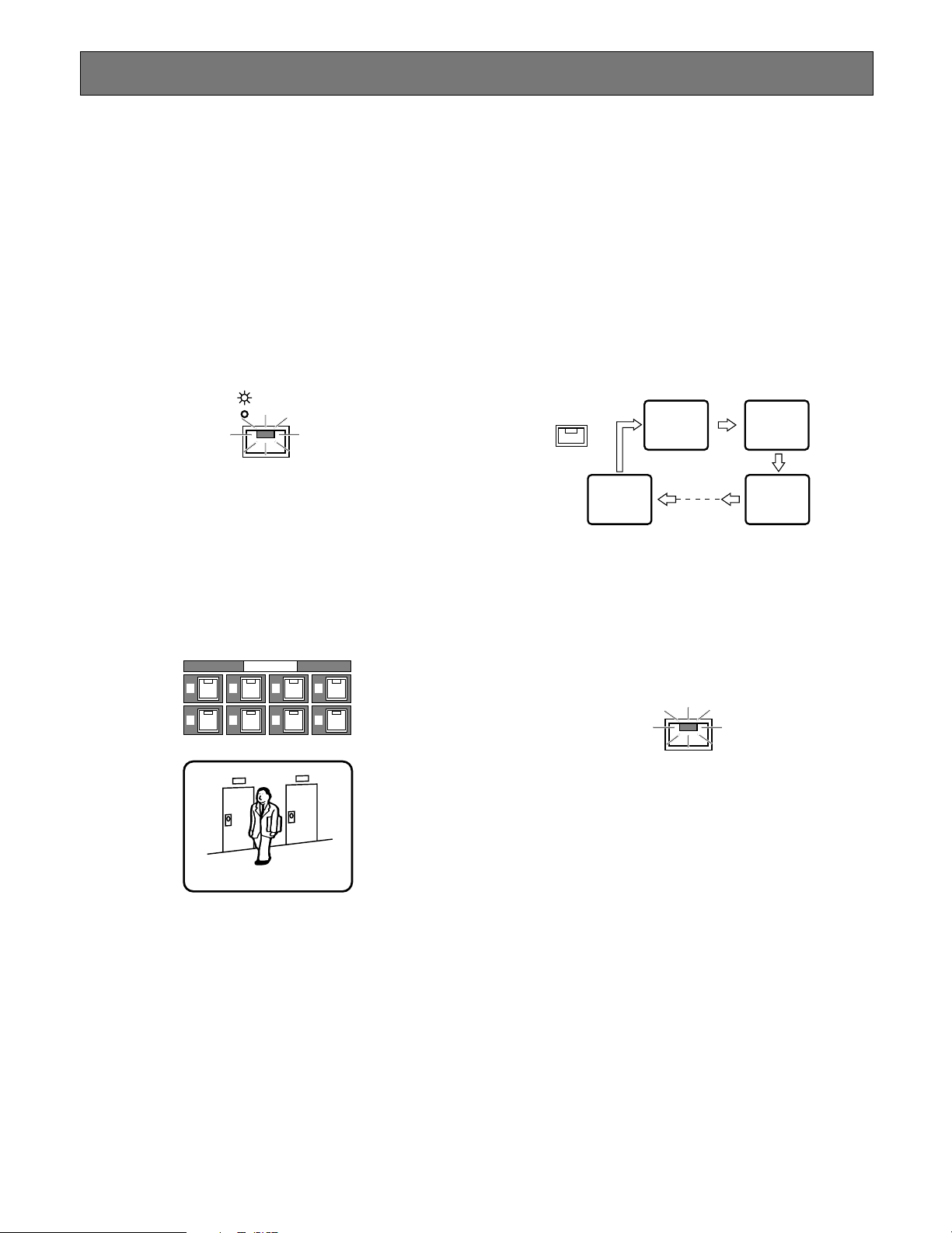
45
OPERATING PROCEDURES
Controlling Video Inputs & Monitors
Operations on the front panel can control video inputs on
the spot monitor or multiscreen monitor.
■ On the Spot Monitor
● Selecting the Spot Monitor
1. Press the [SPOT/MULTI] button to turn the LED in the
button on. The spot monitor is ready to be operated.
2. Follow the descriptions below for each monitoring mode
on the spot monitor.
● Viewing a Single Live
A selected live image is displayed on the spot monitor until
a new input selection is made.
1. Press any numeric button from 1 - 8.
The selected image appears on the monitor.
2. Press another numeric button to select a new input.
● Viewing a Single Live Sequence
The spot monitor can display a single live sequence.
A series of input images is displayed in succession on the
spot monitor. One sequence can be programmed in the
SPOT SEQ SETUP menu setup with an input assignment
and display duration for each step.
1. Select the spot monitor.
2. Press the [SEQUENCE] button to run the sequence.
The LED in the [SEQUENCE] button lights up.
Spot monitor
While running, the LED of the input image presently displayed on the monitor will illuminate in the corresponding numeric button.
3. During the sequence, press the [SEQUENCE] button to
pause. The LED in the [SEQUENCE] button blinks.
4. Press the [SEQUENCE] button to restart the sequence.
The LED turns to a steady light.
5. Press any of the numeric buttons to quit the sequence
and return to spot monitoring.
Notes:
• The Auto Skip function can be programmed in the
menu setup to be applied to the sequence to skip any
steps where no video signal is present.
• You can individually run a sequence on the spot monitor and on the multiscreen monitor. Select a monitor
with the [SPOT/MULTI] button, then press the SEQ button to start or pause a sequence on the respective
monitor.
SPOT
MULTI
CAMERA SELECT
1
2
3
4
5
6
7
8
SEQUENCE
8
12
3
SEQUENCE
Page 46

46
■ On the Multiscreen Monitor
● Selecting the Multiscreen Monitor
1. Press the [SPOT/MULTI] button to turn the LED in the
button off. The multiscreen monitor is ready to be operated.
2. Follow the descriptions below for each monitoring mode
on the multiscreen monitor.
● Viewing a Single Live
The multiscreen monitor can display a single live spot
image.
Operating procedures are the same as for "On the Spot
Monitor" except for selecting the multiscreen monitor.
● Zooming a Single Live
A single live or playback image on the multiscreen monitor
can be zoomed.
1. Display the desired single live or playback image on
the multiscreen monitor pressing the [ZOOM] button an
appropriate number of times.
2. Hold down the [ZOOM] button for 2 seconds to enlarge
the image.
3. Rotate the JogDial to move the zoomed area to the right
and left, or press the [D] or [C] button to move the
area up or down.
4. Press the JogDial repeatedly to select an appropriate
enlargement ratio.
Pressing the JogDial : Increases the ratio (x2 → x4)
5. Hold down the [ZOOM] button for 2 seconds to cancel
the zoom mode.
Notes:
• The maximum zooming ratio (x4) will be reduced to x2
when SIF is selected for RESOLUTION in the SYSTEM
SETUP menu.
• To quit enlargement
•
While displaying a zoomed live image, pressing the
[PLAY] button will quit enlargement and start normal
playback.
•
While displaying a zoomed playback image, pressing
the [STOP] button will quit enlargement and display a
live image.
•
For other cases, hold down the [ZOOM] button for 2
seconds.
• The images on the screen may wave vertically when
enlarging live or playback images in the SIF mode. It is
recommended that you select NORMAL for RESOLUTION when the display quality is considered much
important.
● Viewing a Quad Live Sequence
A series of quad and single images is displayed in succession on the multiscreen monitor. One sequence can be programmed in the MULTI SEQ SETUP menu with an input
assignment and display duration for each step.
1. Select the multiscreen monitor.
2. Press the [SEQUENCE] button to run the sequence.
The LED in the [SEQUENCE] button lights up.
Note: During the sequence, the LEDs of the [CAMERA
SELECT] buttons light up corresponding to the
selected cameras that send images to the monitor.
Multiscreen monitor
3. During the sequence, press the [SEQUENCE] button to
pause. The LED in the [SEQUENCE] button blinks.
4. Press the [SEQUENCE] button to restart the sequence.
The LED turns to a steady light.
SPOT
MULTI
MULTISCREEN
SELECT
ZOOM
MULTISCREEN
SELECT
ZOOM
SEQUENCE
(4A)
1
132
2
4
Page 47

47
● Connected Alarm Sensors
A maximum of eight sensors can be connected to the terminals on the rear panel. Sensors may be installed in such
places as parking lots or reception desks where cars and
visitors come and go.
● Built-in Motion Detector
The recorder detects motion for each of the eight video
inputs, based on certain changes in the video signal.
● Built-in Video Loss Detector
The recorder detects any disconnection of the video inputs.
The images of the disconnected channel will not be recorded.
● PC Alarm
The recorder receives an alarm from a PC.
■ Alarm Output
The following outputs will be performed when TRIGGER
ACTION SETUP is set to REC&ALM in the REC SETUP
menu. Only recording will be performed when set to REC,
and no action will take place when set to OFF.
● Front Panel Indicators
When an alarm is received, the ALARM indicator blinks and
the LED in the corresponding [CAMERA SELECT] button
blinks. More LEDs will blink when more alarm inputs arise.
The LED will stop blinking when the preset time has
elapsed (Auto Reset), when the [RESET] button is pressed
on the front panel (Manual Reset), when the external reset
signal is received on the rear panel (External Reset), or
when the video signal lost on any channel is restored
(Video Loss).
The ALARM indicator will change from blinking to a steady
light when Auto Reset or External Reset is implemented.
This steady light notifies the system operator that there
have been alarm activations that have not yet been manually reset.
5. Press any of the numeric buttons to quit the sequence
and return to spot monitoring.
Notes:
• The Auto Skip function can be programmed in the
menu setup to be applied to the sequence to skip any
steps where no video signal is present.
• You can individually run a sequence on the spot monitor and on the multiscreen monitor. Select a monitor
with the [SPOT/MULTI] button, then press the SEQ button to start or pause a sequence on the respective
monitor.
● Viewing a Multiscreen Live
The multiscreen monitor can display multiscreen live
images. The available split patterns are: Quad A (input 1, 2,
3, 4), Quad B (input 5, 6, 7, 8), and 9-split (input 1-8).
1. Press the [MULTI SCREEN SELECT] button repeatedly.
The pattern changes every time the button is pressed
depending on the setup for MULTI SEQ SETUP.
When ALL is selected:
Pattern 4A → Pattern 4B → Pattern 9 → Pattern 4A
When QUAD ONLY is selected:
Pattern 4A → Pattern 4B → Pattern 4A
Alarm Control Function
The recorder performs alarm functions to warn the system
operators when an event has occurred.
■ Alarm Input
There are four alarm inputs to the recorder that allow the
recorder to output warnings.
MULTISCREEN
SELECT
MULTISCREEN
SELECT
(4A) (4B)
1
3
(4A) (4B)
1
3
MULTISCREEN
SELECT
2
4
9-split screen
123
456
78
MULTISCREEN
SELECT
2
4
MULTISCREEN
5
7
SELECT
5
7
6
8
6
8
ALARM
SUSPEND
RESET
CAMERA SELECT
1
5
2
6
3
7
4
8
Page 48

48
● Monitor Display
There are two monitoring modes, alarm associated (SPOT)
mode and alarm ignore (OFF) mode, depending on the
selection for MONITOR MODE in the ALARM SETUP menu.
Typical cases are described below for each setup.
Alarm Associated Mode
• The image of the alarmed input is displayed on the multiscreen monitor in single spot mode, interrupting whatever live, playback, single or multiple image previously
displayed. When a new alarm is received, the last activated input image will be displayed.
• The blinking camera title and "ALARM" indication on the
monitor will be alternately. For example, when an alarm
is received from CH1, "CH1 ALARM" will be displayed
on the monitor.
• Combination cameras connected to VIDEO IN 1-4 can
be aimed at the preset position if is specified for PRESET in the TRIGGER ACTION SETUP of the REC SETUP
menu.
• When a camera signal loss has occurred, the monitor
display switches to a blackout screen with the channel
number indicated, for example, "CH 1 LOSS".
Alarm Ignore Mode
• The images being displayed will remain on the monitor
screen when an alarm arises, but the "ALARM" status
indication will appear.
The following outputs for each channel will be enabled or
disabled depending on the settings made in the TRIGGER
ACTION SETUP menu.
• The following will be disabled when OFF is selected for
the channel.
• The following will be enabled when REC&ALM is selected for the channel.
• Only alarm recording will be enabled when REC is
selected for the channel.
● Alarm Recording
The recorder starts alarm recording with the preset rate and
picture quality, if applicable. See ALARM RECORDING for
details.
● Alarm Buzzer
The buzzer sounds when an alarm is input, if applicable.
● Alarm Log Recall and Search
The alarm events are stored in the log for later reference.
● Alarm Status Output
The active status and recovery status are output to the
external devices via the terminals on the rear panel.
● Alarm Notice Mail
When connected to the Ethernet, the recorder sends an email to notify the preset URL that the alarm is activated.
● Resetting Alarm
See below.
● Suspending Alarm
See below.
■ Resetting Alarm
The activated alarm is reset by any of the inputs: manual
(all) reset, auto reset, external reset, or pressing the [REC
STOP] button.
Resetting changes the status of the recorder as follows.
• The recorder stops alarm recording.
• The buzzer, if activated, stops beeping.
• The recorder outputs an alarm recovery signal from the
rear panel.
• The Alarm Out signal on the rear panel is reset.
● Manual (All) Reset
Pressing the [RESET] button on the front panel will clear all
operating alarms, and allow the blinking or lit ALARM indicator to go off.
CAM1 CH1ALARM
CAM1 CH1LOSS
ALARM
SUSPEND
RESET
Page 49

49
● Auto Reset
The activated alarm event is reset when the AUTO RESET
time has elapsed, or the lost video has been recovered.
The ALARM indicator changes from blinking to a steady
light.
● External Reset
The activated alarm event except video motion detection, is
reset when the recorder receives an external reset signal
from the connected device via the REMOTE/ALARM connector on the rear panel.
The ALARM indicator changes from blinking to a steady
light.
● Pressing REC STOP Button
Pressing the [REC STOP] button resets alarm status and
recording when MONITOR MODE is set to OFF. When
SPOT is set, only the [ALARM RESET] button will reset
alarm status and recording.
■ Suspending Alarm Input
This function may be convenient during setup procedures.
When enabled, any alarm input is ignored and the recorder
performs as follows.
• The alarm event will be stored in the alarm log.
• The recorder enters alarm recording.
• The alarm buzzer does not sound.
• The SUSPEND indicator lights up.
1. Hold down the alarm [RESET] button and [LOCK] button simultaneously to enable the suspension function.
The SUSPEND indicator lights up.
2. Do the same as above to reset the suspension function.
The indicator turns off.
■ Alarm Log Recall & Search
The ALARM RECALL window displays the alarm event log
in chronological order with event numbers, dates, times,
and the activation sources. A maximum of 9 999 events can
be stored, and older records will be erased when more
events arise.
T: Alarm terminal was activated.
V: VMD was activated.
P: Alarm event notification from the PC.
Note: In some cases the log displayed in the ALARM
RECALL list may apply to the previous alarm record
that was overwritten after selecting CONTINUE for the
DISK END MODE. This is because the alarm log is
updated later than the image data.
● To Browse through Log
1. Hold down the JogDial for 2 seconds. The monitor displays the ALARM RECALL list.
2. Rotate the JogDial to scroll up or down the page.
Scrolling speed is selected in the menu setup.
3. Hold down the JogDial for 2 seconds to quit the ALARM
RECALL list and go back to the previous window.
● To Sort by Channel
1. Hold down the JogDial for 2 seconds to display the
ALARM RECALL list. The log of all channels appears.
2. Press the desired channel [CAM SEL] button. The indicator on the button lights up, and only the log of the
selected channel will be displayed.
3. Press another channel button to select a new channel.
REC STOP
ALARM RECALL YEAR03
NO. DATE TIME ALM
1543 OCT30 23:58:12 T1
1542 OCT30 23:52:54 V2
1541 OCT30 23:40:29 V3
1540 OCT30 23:39:50 T4
1539 OCT30 23:35:41 P2
1538 OCT30 23:30:22 P1
1537 OCT30 23:25:55 T2
1536 OCT30 23:21:09 T2
(TOTAL 1543EVENTS)
TO SEARCH PUSH T&D KEY
ALARM RECALL YEAR03
NO. DATE TIME ALM
0003 OCT20 23:52:54 V2
0002 OCT20 23:51:54 V2
0001 OCT20 23:50:54 V2
PUSH JOG→DATA CLEAR
(TOTAL 1543EVENTS)
TO SEARCH PUSH T&D KEY
ALARM
SUSPEND
RESET
TIMER
REMOTE
LOCK
Page 50

50
Recording
Notes:
• When SIMUL REC&PLAY (simultaneous recording and
playback) is set to OFF in the setup, any recording will
stop playback and start the recording. Playback is
unavailable while recording.
• When set to ON, recording is available while playing
back.
• The recording rate will degrade to 15 FPS while displaying a quad split screen.
■ Internal Timer Recording
When INT is set for TIMER in the WJ-HD220 MAIN menu,
the presets made in the internal timer will take effect.
Internal timer recording begins when the preset start time
comes and continues until the preset end time comes. Up
to four programs, containing four events each, can be
assigned to the weekly and/or daily schedule.
Notes:
• When SIMUL REC&PLAY is set to OFF, a preset recording interrupts playback and starts at the preset start
time.
• When you set both the start and end time of an event to
the same hour, the event will not be recorded.
• When planning to record all day long, set the start time
to 00:00 and the end time to 24:00 for the final event.
• When planning to record through midnight:
Set 24:00 for the end time of the final event of the day.
Set 00:00 for the start time of the initial event of the next
day.
4. To return to the all-channel list, press the button of the
selected channel (now lit) or the [MULTISCREEN
SELECT] button.
● To Search for Playback
1. Move the cursor to the desired event in the list, using
the [D] or [C] button.
2. Press the [PLAY] button to play back the recorded picture. The LED in the [PLAY] button lights up. The alarm
log on the monitor disappears.
3. Press the [STOP] button to stop playback. The alarm
log appears again on the monitor.
4. Hold down the JogDial for 2 seconds to quit the alarm
log search.
● To Erase Log
All event records can be erased.
1. Move the cursor to "PUSH → DATA CLEAR", then press
the JogDial.
2. Rotate the JogDial to select YES or NO.
YES: Enables the log erasure.
NO: Disables the log erasure.
3. Press the JogDial to carry out the selection.
Note: You can access pictures recorded on the disk by
time & date search even after they have been
erased.
PROG1 SETUP
NO. START END MODE
1→ 8:00 12:20 SETO
2→ 13:00 15:00 SETO
3→ : :
4→ : :
Page 51

51
Orange: The channel image is not displayed.
Yellow: The channel image is displayed.
The multiscreen monitor displays the recording images
while the corresponding input indicators on the front
panel light in yellow.
2. Hold down the [REC STOP] button for 2 seconds to
stop recording. The REC indicator turns off.
■ Alarm Recording
Alarm recording starts when an externally connected sensor is turned on, the built-in VMD (Video Motion Detector) or
the built-in video loss detection is activated.
Alarm recording will proceed, then stop when the postrecording time has elapsed.
If more than one alarm arise, for instance ALM1 and ALM2,
the images of the alarmed inputs are recorded on the disk
as shown in the figure.
Note: HDD indicator will continue to blink for a period
equivalent to the specified pre-alarm time at the end of
alarm recording.
■ Power-on Recording
For power-on recording, select EXT for TIMER in the WJHD220 MAIN menu. The recorder starts recording when AC
power is supplied.
This enables the disk recorder to start recording everyday
at a specific time by the use of a timer switcher that controls the AC mains supplied to the recorder. The power
switch on the rear of the recorder must be turned on in this
case.
■ Manual Recording
Manual recording is available when OFF is set for TIMER in
the WJ-HD220 MAIN menu. The menu setup can exempt
specific inputs from manual recording for the purpose of
preserving disk capacity. The recording mode (SF-24, for
example), picture quality (fine) and recording rate (30 fps)
are set in the menu setup by specifying two of the three
parameters. SF-24H is an example having a picture quality
of especially fine grade and 48 hours of recording capacity.
1. Press the [REC] button on the front panel to start
recording. The indicator in the [REC] button lights up
while the [CAM SEL] button of the channel indicates
and the channel image is displayed on the multiscreen
monitor.
Timer
Switch
AC Mains
SET
OPERATE
SUSPEND
DST
ALARM
TIMER
REMOTE
OSD
LOCK
RESET
SEQUENCE
SPOT
MULTI
CAMERA SELECT
1526374
HDD
STOP
PLAY
SETUP
/ESC
FULL
MULTISCREEN
ALARM
SELECT
SERCH
ERROR
8
ZOOM
PLAY MODE SELECT
REC STOP
REC
TIME&DATE
SEARCH
PUSH— PAUSE
ALARM
RECALL
Digital Disk Recorder WJ-HD220
Start
C1 C2 C3 C4 C5 C6 C7 C8 C1
Stop
REC STOP
TIME&DATE
SEARCH
Sensor
SET
OPERATE
Built-in
VMD
SUSPEND
MULTI
REMOTE
RESET
1526374
LOCK
OSD
SEQUENCE
HDD
STOP
PLAY
SETUP
/ESC
FULL
MULTISCREEN
ALARM
SELECT
SERCH
ERROR
8
ZOOM
PLAY MODE SELECT
CAMERA SELECT
SPOT
DST
ALARM
TIMER
C1C2C3C4C8C1C2C3C4C8C1C2C3C4C8C1C
REC STOP
REC
TIME&DATE
SEARCH
PUSH— PAUSE
ALARM
RECALL
Digital Disk Recorder WJ-HD220
2
REC
Alarm 1
C4C8C1C1C1C1C1C2C1C2C2C2C2C2C3C4C
Alarm 2
8
Alarm 1 Duration
Alarm 2 Duration
Page 52

52
3. Rotate the JogDial clockwise to move forward in the
recorded data or counter-clockwise to move backward.
The more turns you rotate the JogDial, the faster the
skip speed will be.
4. Press the [STOP] button to stop playback.
■ Step Playback
A minute search is made for a desired picture field by field.
1. Press the [PLAY] button to start playback.
2. Press the [STEP] button to start step playback. The LED
in the button blinks.
3. Rotate the JogDial clockwise to advance to the next
later field or counter-clockwise to rewind to the next
older.
4. Press the [STOP] button to stop playback.
■ Alarm Search Playback
Alarm records on the disk are searched while viewing the
beginning image of the record.
1. Press the [PLAY] button to start playback.
2. Press the [ALARM SEARCH] button to start alarm
search playback. The LED in the button lights up.
3. Rotate the JogDial one click clockwise or counterclockwise. The display advances to the beginning of
the next later or next older record. Repeat until the
desired record is displayed.
Playback
In playback modes, the recorded image data are played
back.
Notes:
• Alarm recording will interrupt playback if SIMUL
REC&PLAY is set to OFF, or will allow playback to continue if set to ON.
• Operation of the [PLAY] button will be ignored if the
disk is empty, for instance, when the recorder is used
for the very first time or right after formatting of the disk.
• The latest recorded image is displayed on the monitor
right after recording finishes. Search for the desired
image by skip playback before starting playback.
■ Normal Playback
The pictures recorded on the disk are played back sequentially.
1. Press the [PLAY] button to start playback.
2. Press the JogDial [PUSH–PAUSE] to pause and restart
playback.
3. Press the [STOP] button to stop playback.
■ Skip Playback
Picture search is available in quick forward and backward
playback. The monitor displays the skip speed as 1/2PLAY,
PLAY, 2PLAY, 1FF, 2FF, 3FF, and so forth. The asterisk indicates that images are played back continuously without
skipping.
1. Press the [PLAY] button to start playback.
2. Press the [REW/FF] button to start skip playback. The
LED in the button lights up.
SET
SETUP
/ESC
STOP
13
PLAY
PUSH– PAUSE
ALARM
RECALL
14
SETUP
/ESC
STOP
PLAY REC
PLAY MODE SELECT
PUSH— PAUSE
ALARM
RECALL
23
SET
2
SETUP
/ESC
STOP
ALARM
SERCH
PLAY MODE SELECT
14
PLAY
REC
PUSH— PAUSE
ALARM
RECALL
23
SET
1,45
SETUP
/ESC
STOP
ALARM
SERCH
PLAY MODE SELECT
PLAY REC
PUSH– PAUSE
ALARM
RECALL
2
SET
3
Page 53

53
6. Repeat from step 1 to search for another time and date
or press the [TIME&DATE SEARCH] button to cancel
the function. Pressing the [STOP] button will also end
the searching.
Note: Searching may take the recorder 18 seconds at
worst
■ Multiscreen Playback
You can view a multiple playback image displayed in 4-split
or 9-split pattern on the monitor at a time.
• Normal Playback
Press the [PLAY] button to start normal playback. The
image data recorded on the disk are sequentially
played back, and the monitor displays images in the
single display mode or multiscreen display mode.
• Multiscreen Playback
Press the [MULTI SCREEN SELECT] button an appropriate number of times. The monitor display changes as
follows. The LEDs in the [MULTI SCREEN SELECT] button and respective input buttons will light up.
Single Image → Quad A (4A/comprising inputs 1, 2, 3,
and 4) → Quad B (4B/inputs 5, 6, 7, and 8) → Nine-spit
(inputs 1 - 8) → Quad A → Quad B → Nine-split
• Specific Input Playback
Press the respective input button. The images of the
selected input are played back continuously and displayed on the monitor.
• Stop Playback
Press the [STOP] button to stop playback.
Note: When the playback proceeds to where recording
is executed on the disk, the recorder will pause
playback and freeze the displayed image on the
monitor.
4. Press the [PLAY] button to play back the searched
record.
5. Press the [STOP] button to stop playback.
Note: "Alarm Search Playback" and "Alarm Log Recall"
are similar, but different in operations. Refer to
■ Alarm Log Recall & Search on page 49.
■ Time & Date Search Playback
A picture record of a specified time and date is played
back.
1. Press the [TIME&DATE SEARCH] button. The monitor
displays the time & date search window.
2. Press the [D] or [C] button to move the cursor to the
next position.
3. Rotate the JogDial clockwise to increase the parameter
or counter-clockwise to decrease it.
4. Repeat steps 2 and 3 above until the desired parameters are selected.
5. Press the [PLAY] button to start playback. The monitor
displays the single spot image when an input is selected or the nine-split image when all input is specified.
The recorder stops searching when the playback
reaches the end of the record.
5
PLAY
2
JAN31.04 23:00:00
TO SEARCH PUSH PLAY KEY
REC
REC STOP
TIME&DATE
SEARCH
13
PUSH— PAUSE
ALARM
RECALL
SET
MULTI SCREEN
SELECT
ZOOM
HDD
FULL
ERROR
SETUP
/ESC
STOP
ALARM
SERCH
PLAY MODE SELECT
PLAY REC
Page 54

54
Lock/Unlock Buttons
■ Password Verification
When a locked button is pressed, the key locked warning
appears on the monitor for 2 seconds, then it changes to
the password prompt.
1. Enter your five-digit password using the [CAM SELECT]
buttons (1-8). The buzzer shortly beeps once, and the
entered digit changes from "–" to "*" on the monitor.
2. The prompt window will display "KEY UNLOCKED!" for
2 seconds, and the buzzer beeps twice if the correct
password is entered.
The monitor returns to the previous display. The
recorder allows access to the front panel controls if a
button operation takes place within 5 seconds of password entry.
3. Retry verification when password error appears on the
monitor.
The recorder will exit from verification if there is no operation within 30 seconds.
■ Enabling Button Lock
1. You need to register passwords in the SYSTEM SETUP
window prior to operating your system.
2. Press the [LOCK] button for 2 seconds.
The buzzer shortly beeps twice, and the LED in the button lights up. The "KEY LOCK DONE!" message
appears on the monitor.
Note: Set PASSWORD LOCK to OFF if you do not want
the recorder to revert to button lock mode when no
operation takes place within 5 minutes.
PASSWORD
/-----
LOCK
KEY LOCK DONE!
Page 55

55
WJ-HD220 NETWORK OPERATION
Page 56

56
■ System Requirements
Your personal computer must meet the following minimum requirements.
OS:
One of the following operating systems:
Windows98 Second Edition
Windows2000
Windows Millennium Edition
WindowsXP Professional or Home Edition
Browser:
One of the following browser software:
Microsoft Internet Explorer 5.5SP2, 6.0
Note: The Netscape browsers are not applicable.
Display:
1 024 x 768 pixels or more
Trademarks
Microsoft, Windows, WindowsXP and Internet Explorer are either registered trademarks or trademarks of Microsoft Corporation in the United
States of America and/or other countries.
PREPARATIONS
Page 57

57
■ Connection
System connection examples are shown.
<Direct Connection with a PC>
• Connection with a Client PC via Hub
<System Expansion>
A maximum of four PCs can access the recorder at a time.
CL920
CL920
CL920
Camera
WV-
OPERATE
CAMERA SELECT
SPOT
DST
TIMER
ALARM
MULTI
REMOTE
SUSPEND
RESET
1526374
OSD
SEQUENCE
LOCK
HDD
STOP
SETUP
/ESC
FULL
MULTISCREEN
ALARM
SELECT
SERCH
ERROR
8
ZOOM
PLAY MODE SELECT
PLAY
REC STOP
REC
TIME&DATE
SEARCH
PUSH— PAUSE
ALARM
RECALL
Digital Disk Recorder WJ-HD220
Ethernet Cross Cable
SET
Digital Disk Recorder
Camera
Super Dynamic
MULTI
SUSPEND
REMOTE
OPERATE
RESET
1526374
OSD
SEQUENCE
LOCK
HDD
SETUP
/ESC
FULL
MULTISCREEN
SELECT
ERROR
8
ZOOM
CAMERA SELECT
SPOT
ALARM
TIMER
DST
Digital Disk Recorder
Cameras 1-8
WV-
WV-
ALARM
SERCH
STOP
PLAY MODE SELECT
PLAY
REC
SET
PUSH— PAUSE
REC STOP
TIME&DATE
SEARCH
ALARM
RECALL
Digital Disk Recorder WJ-HD220
System
Administrator
Ethernet
Straigth
Cable
LAN
Personal Computer
Ethernet
Straigth
Cable
Hub
Personal Computer
User User
Hub
DST
CAMERA SELECT
SPOT
TIMER
ALARM
MULTI
REMOTE
SUSPEND
OPERATE
RESET
1526374
OSD
SEQUENCE
LOCK
HDD
STOP
SETUP
/ESC
FULL
MULTISCREEN
ALARM
SELECT
SERCH
ERROR
8
ZOOM
PLAY MODE SELECT
Digital Disk Recorder
PLAY
REC STOP
REC
TIME&DATE
SEARCH
PUSH— PAUSE
ALARM
RECALL
Digital Disk Recorder WJ-HD220
Hub
SET
User User
Page 58

58
■ Main Page and Control Panel
Start your PC WWW browser. Type http://192.168.0.10/ (or
the IP Address set for WJ-HD220) / in the URL (Uniform
Resource Locators) space.
The browser displays the Main Control Panel of the WJHD220 homepage as shown in the figure.
Notes:
• Specify "http//:192.168.0.10/" when a client PC is connected alone.
• Specify "http//: (IP address previously set for the WJHD220)/" such as a LAN connection.
• A maximum of four PCs can access the recorder at a
time.
About Picture Quality
Picture quality transferred via the network depends on the recorder's status as follows.
Recorder Status Displayed Quality
Timer recording Preset recording quality
Pre-alarm period Preset alarm recording quality
Except pre-alarm period Preset manual recording quality
Playback Recorded quality on the disk
Page 59

59
■ To Access Setup Menus
There are fourteen setup menus to adapt the WJ-HD220 to
your requirements.
1. On the Main Control Panel, click the [SETUP MENU]
button. The setup menu opens.
2. Click the buttons to open the respective windows.
<Main Setup Menu>
TIMER SETUP: Specifies the schedule and parameters
for timer recordings.
REC SETUP: Specifies the parameters for manual and
alarm recordings.
EXT REC SETUP: Selects optional parameters to be
applied to the recording while the switch connected
externally to the EXT REC terminal turns on.
DISPLAY SETUP: Specifies time-and-date and other
displays of status information.
SYSTEM SETUP: Specifies password-protection, and
simultaneous REC&PLAY.
ALARM SETUP: Specifies alarm-related monitoring
mode, and VMD (video motion detector) mode.
COMMUNICATION SETUP: Specifies parameters for
serial and network communications.
SWITCHER SETUP: Specifies sequence and multi-split
patterns.
WJ-HD220 SETUP
SYSTEM INFORMATION: Displays various system
information.
<Network Setup Menu>
USER SETUP: Specifies users, passwords, and
access levels.
HOST SETUP: Specifies hosts and access levels.
FTP SETUP: Specifies parameters for transmitting files.
MAIL SETUP: Specifies senders, and receivers.
NETWORK VIDEO SETUP: Specifies application soft-
ware for video translation, and sequence steps.
3. To return to the MAIN CONTROL PANEL, click the
[Main Control Panel] tab or [BACK] button in the window.
■ Timer Setup (TIMER SETUP)
● Timer Recording (TIMER REC)
OFF: Runs recording when manually operated, not
using any timer. Recording parameters are specified in the REC SETUP window.
INT: Runs recording with the programmed picture qual-
ity within the time zone scheduled on the internal
timer.
EXT: Runs recording when the externally connected
timer switch turns on and supplies power to the
recorder (Power-on recording). Recording parameters are specified in the REC SETUP window.
Note: Buttons in the setup menus may appear with a
thicker border when using a browser in WindowsXP.
Page 60

60
● Program Assignment (TIMER REC)
When internal timer (INT) is selected, programs can be
assigned on a weekly and/or daily basis.
Assignable programs: PROG1 – PROG4, OFF
● Programming (PROGRAM SETUP)
There are four programs, each containing four events having a start and end time, and a recording mode.
1. Select ON or OFF for each event.
ON: Applies the schedule and mode to the program.
OFF: Does not apply.
2. Enter the start and end times.
Assignable START times: From 00:00 to 23:59
Assignable END times: From 00:00 to 24:00
3. Click the SET button.
4. Click the mode SETUP button. The PROG1-4 No.1-4
window opens.
● Recording Mode Setup (PROG1-4
NO.1-4 SETUP)
Parameters for internal timer recording are assigned to
each event (NO.1-4) of the program (PROG1-4) in this window. There are five recording modes available: super fine
(SF), fine (FQ), normal (NQ), long-time (EX) and optional
(SP). If combined with audio recording (-A), the number of
recording modes doubles. The selected recording mode
determines the remaining recording time displayed on the
monitor.
In the SP mode, the field rate and picture quality are variable, and can be selected at option in the range of 0.1 to
30 FPS with five quality level options respectively. After the
recording mode is selected, the available recording time is
determined and displayed.
N/A
Rec Mode Quality Audio Record Note
SF-xxxH Super Fine N/A
Field rate, quality
selected optionally
Field rate, quality
selected optionally
N/A
N/A
N/A
Available
Available
Available
Available
Fine
Normal
Long time
Optional setup
Super Fine
Fine
Normal
Long time
FQ-xxxH
NQ-xxxH
EX-xxxH
SP-xxxH
AvailableOptional setupSP-AxxxH
SF-AxxxH
FQ-AxxxH
NQ-AxxxH
EX-AxxxH
Notes:
• By selecting a recording time, the recording rate (REC
RATE) and the recording quality (REC QUALITY) will be
automatically calculated and displayed. For details,
refer to the provided booklet "REC MODE TABLES for
WJ-HD220".
Page 61

61
• Even if preset to 30 or 15 FPS, the actual recording rate
may drop to 7.5 FPS at worst while busy multi task such
as playback, remote-access playback, remote-access
live image, FTP access, multi-split display, or video
motion detection are carried out simultaneously.
The status display will indicate "*→ PLAY" while playing
back the images recorded with a rate different from the
preset.
• The suffix "xxx" following "SP-" is specified in REC
MODE TABLE in the ADDENDUM attached to the manual.
1. Select a recording mode. Audio data will be recorded
when a mode with hyphen A is selected.
Available recording modes: SF, FQ, NQ, EX, SP, SF-
A, FQ-A, NQ-A, EX-A, and SP-A
2. When SP or SP-A is selected, specify a recording rate
(REC RATE).
Available recording rates: From 0.1 to 30 FPS
3. When SP or SP-A is selected, specify a recording quality (REC QUALITY).
Available recording qualities: SUPER FINE, FINE,
NORMAL, EXTENDED
8 Alarm Recording Mode Setup (ALM REC MODE)
Recording of alarm events arising within the time zone
specified by the program will start with the preset parameters.
Refer to "PROG NO. SETUP" described above for operating
procedures and available parameters, since they are very
similar.
8 Pre-alarm Recording (PRE ALM REC)
Available times (seconds): 0S, 1S, 2S, 3S, 4S, and 5S
8 Post-alarm Recording (POST ALM REC)
Available times (seconds): 5, 10, 20, 30
Available times (minutes): 1, 1.5, 2, 3, 6
Continue: Recording continues until the [RESET] but-
ton is pressed, or the RESET IN signal is supplied to
the rear panel.
Manual: Recording continues while the alarm input is
active, or at least for 10 seconds if the input turns
inactive earlier.
8 Dynamic Recording (DYNAMIC REC)
ALM-MULTI: Alarm activated channels are recorded
with priority over others.
OFF: All channels are recorded with the same priority.
■ Trigger Action Setup (TRIGGER ACTION SETUP)
This menu specifies the actions the recorder will take for
each event when an alarm arises. The program number
and event number in the second line of the menu will disappear when the screen is changed from the REC SETUP
menu.
8 Mode (MODE)
OFF: Disables alarm recording, logging, or warning.
REC&ALARM: Enables all alarm recording, logging
and warning.
REC: Enables alarm recording, but disables warning.
Notes:
• Moving the combination cameras to the preset position
can be set only from the REC SETUP menu, not from
the Program 1-4 menu.
• To open the menu for setting positions, click the [TRIGGER ACTION SETUP] button in the REC SETUP menu.
Click the [SET] button when items have been set properly.
Page 62

62
■ Camera Recording Setup (REC CAMERA SETUP)
Click CAMERA REC SETUP in the system setup window to
open the menu.
This menu is provided for the purpose of saving disk
space. Each camera channel can be recorded only when
an alarm operates, while it will not be recorded in non-alarm
status.
ALARM-ONLY: Records the camera channel only
when the alarm operates.
REC: Records the camera channel regardless of alarm
or non-alarm status.
■ Manual Recording Setup (REC SETUP)
Manual recording will take effect when OFF (not INT or EXT)
is selected in the Timer Mode Selection TIME REC window.
The parameters for alarm recording will be applied except
for the scheduled time zone if INT is selected.
Click the [REC SETUP] button on the setup control panel to
open the window.
Refer to ● Recording Mode Setup PROG1-4 SETUP, NO. 14 for operating procedures and available parameters.
■ Trigger Action Setup (TRIGGER ACTION SETUP)
This menu appears when the [TRIGGER ACTION SETUP]
button in the REC SETUP menu is clicked.
8 Mode (MODE)
OFF: Disables alarm recording logging, and warning.
REC&ALARM: Enables alarm recording logging, and
warning.
REC: Enables alarm recording, but disables warning.
8 Camera Preset Position (PRESET)
When combination cameras are connected to VIDEO IN
1-4 on the rear panel and positions are specified
beforehand, you can assign a position to cameras 1-4.
1-64: Moves the camera to the specified preset posi-
tion.
HOME: Moves the camera to the home position.
– –: Does not move the camera.
Note: Preset move will not function for cameras 5-8 or
for cameras 1-4 if they are cameras other than combination cameras.
Click the [SET] button when the items have been set properly.
Page 63

63
TYPE2 12H: Time and date are displayed in two lines in
the AM-PM system.
OFF: Time & date display is disabled.
8 Time and Date Position (TIME&DATE POSITION)
Right-Lower: Displays time & date in the lower right
corner.
Right-Upper: Displays time & date in the upper right
corner.
Left-Lower: Displays time & date in the lower left cor-
ner.
Left-Upper: Displays time & date in the upper left cor-
ner.
8 Time & Date Embedded (TIME&DATE
EMBEDDED)
ON: The display will be embedded and recorded with
the image data.
OFF: The display will not be recorded.
8 Status Display (STATUS DISPLAY)
ON: Status display is enabled.
OFF: Status display is disabled.
8 Status Display Position (STATUS POSITION)
Right-Lower: Displays status in the lower right corner.
Right-Upper: Displays status in the upper right corner.
Left-Lower: Displays status in the lower left corner.
Left-Upper: Displays status in the upper left corner.
8 HDD Full (HDD FULL)
1% - 99%: The FULL indicator blinks when the remain-
ing capacity reaches the selected value. This will
take effect when DISK END MODE is set to STOP in
the RECORD SETUP.
8 Remote LED (REMOTE LED)
ON: REMOTE LED turns on when the network controls
the recorder.
OFF: REMOTE LED is deactivated.
8 HDD Check (HDD CHECK)
ON 0:00 - 23:00: The recorder checks the HDD at the
specified time every day.
OFF: Check is deactivated.
Click the [SET] button when all items have been set properly.
Click the [CAMERA TITLE SETUP] button to open the CAMERA TITLE window.
■ Externally Specified Recording Mode (EXT REC SETUP)
This window specifies the recording mode and parameters
that will be changed when the switch externally connected
to the EXT REC terminal is turned on.
Refer to ● Recording Mode Setup PROG1-4 SETUP, NO. 14, for operating procedures and available parameters.
■ Display Setup (DISPLAY SETUP)
Time and date display and other displays of status information are specified in this window.
8 Clock Setup (CLOCK SETUP)
Select a month, and type a day, year, hour, and minute.
8 Time and Date Display (TIME&DATE DISPLAY)
TYPE1 24H: Time and date are displayed in one line in
the 24-hour system.
TYPE1 12H: Time and date are displayed in one line in
the AM-PM system.
TYPE2 24H: Time and date are displayed in two lines in
the 24-hour system.
Page 64

64
■ Camera Title (CAMERA TITLE)
8 On/Off (ON/OFF)
ON: Displays the camera title.
OFF: Hides the camera title.
8 Title (TITLE)
Usable characters: Are shown in the window.
Number of digits: 5 digits maximum.
8 Title Position (POSITION)
Right-Lower: Displays the title in the lower right corner.
Right-Upper: Displays the title in the upper right cor-
ner.
Left-Lower: Displays the title in the lower left corner.
Left- Upper: Displays the title in the upper left corner.
Click the [SET] button when all items have been set properly.
■ System Setup (SYSTEM SETUP)
8 Password Lock (PASSWORD LOCK)
Buttons on the front panel of the WJ-HD220 will be
password-protected or freed.
ON: Enables password-protection.
OFF: Disables password-protection.
8 Password All (PASSWORD ALL)
Enter a five-digit password comprising 1 through 8 to
protect normal operations and setup operations from
unauthorized access.
Available numerals: From 11111 to 88888
8 Password Operation (PASSWORD OPERATION)
Enter a five-digit password to protect normal operations
from unauthorized access.
Available numerals: From 11111 to 88888
8 Keylock Buzzer (KEYLOCK BUZZER)
The buzzer will beep or not when a locked button is
pressed.
ON: Enables the buzzer beep.
OFF: Disables the buzzer beep.
8 Skip Alarm Recall (SKIP ALARM RECALL)
Specify the number of pages to be skipped in the alarm
log. The alarm log page will jump the specified pages
when the JogDial is rotated.
Available skip pages: 1, 5, 10, 20, 50
8 Simultaneous Recording and Playback
(SIMULTANEOUS REC&PLAY)
There may be cases where recording is essential while
playback is in progress.
ON: Allows both recording and playback at a time.
OFF: Allows exclusively recording or playback.
Page 65

65
Note: The recording rate may be sacrificed in the fol-
lowing cases.
• Recording and playback/FTP access are carried
out simultaneously.
• A multi-split screen is displayed.
• VMD (video motion detection) is enabled.
• A PC accesses the live images via the network.
8 Alteration Detection (ALTER DETECT)
You can enable or disable the addition of alterationdetection signals in the JPEG data supplied to the network. The default is OFF.
ON: Detects alterations.
OFF: Does not detect.
Note: When set to ON, the data transmission rate on
the network will slow down.
8 Disk End Mode (DISK END MODE)
STOP: Stops recording until a mode other than [STOP]
is selected.
CONTINUE: Old data is automatically overwritten from
the disk start.
8 Disk End Buzzer (DISK END BUZZER)
ON: Enables the buzzer beep at the disk end (remain-
ing space = 0 %).
OFF: Disables the buzzer beep.
8 Play Priority (PLAY PRIORITY)
This setting places priority on a specific access point
for playing back the image data when access collisions
take place.
LOCAL: Places priority on front panel operations.
NET PLAY: Places priority on network access.
FTP GET: Places priority on access to the FTP.
NONE: The latest operation has priority over others.
8 Time Adjusting (TIME ADJUSTING)
The internal timer built into the WJ-HD220 is calibrated
once a day via the Time Adjust In and Out terminals on
the rear panel.
SLAVE: Accepts the calibration signal from the master.
MASTER: Supplies the calibration signal to the slave
units at the specified hour every day.
Page 66

66
■ Video Motion Detector Setup (VMD SETUP)
8 Sensitivity (SENSITIVE)
LOW: Low sensitivity
MID: Medium sensitivity
HIGH: High sensitivity
OFF: Motion detection is disabled.
Click the [SET] button when all items have been set properly.
Click the [SETUP] button to open the area setup window.
■ VMD Area Setup (VMD AREA SETUP)
Drag a maximum of four areas with the mouse to specify
the detection areas.
Click the [SET] button when all items have been set properly.
■ Alarm Setup (ALARM SETUP)
8 Alarm Buzzer (ALARM BUZZER)
ON: Buzzer beeps while alarm is active.
OFF: Buzzer does not beep.
8 Video Loss Detection (VIDEO LOSS DETECT)
OFF: Deactivates the video loss detection.
ON: Activates the detection.
8 Multiscreen Monitor Mode (MONITOR MODE
(MULTI))
SPOT: Switches to the picture of the channel where
alarm has operated.
OFF: Retains the previous display mode.
8 Spot Monitor Mode (MONITOR MODE (SPOT))
SPOT: Switches to the picture of the channel where
alarm has operated.
OFF: Retains the previous display mode.
Click the [SET] button when all items have been set properly.
Page 67

67
8 Parity Check (PARITY CHECK)
NONE: No parity check
EVEN: Even parity
ODD: Odd parity
8 Stop Bit (STOP BIT)
1 bit: 1 bit
2 bit: 2 bits
8 Wait Time (WAIT TIME)
OFF: Retransmission is disabled.
100 MSEC: 100 m seconds
200 MSEC: 200 m seconds
1 SEC: 1 second
8 Control Unit Addresses
(CONTROL UNIT ADDRESS) (only for PS•DATA)
Assignable address: From 1 to 99, must be unique in
the chain.
8 System Unit Address (SYSTEM UNIT ADDRESS)
(only for PS•DATA)
Assignable addresses: From 1 to 99, must be unique
in the chain.
8 Alarm Data (ALARM DATA)
OFF: Select this when no system controller is connect-
ed.
0 SEC: Does not pause.
1 SEC: Pauses for 1 second.
5 SEC: Pauses for 5 seconds.
Click the [SET] button when all items have been set properly.
Click the [CAMERA SYSTEM SETUP] button. The CAMERA
SYSTEM SETUP window opens.
■ Communication Setup (COMMUNICATION SETUP)
Click the [SERIAL PORT SETUP] or [NETWORK SETUP]
button. The respective window opens.
■ Serial Port Setup (SERIAL PORT SETUP)
8 Protocol Selection (PROTOCOL SELECT)
PS•DATA: Select when the communication chain uses
the PS
•
DATA protocol.
When selected, the DATA terminal on the rear panel
can be used.
RS-232C: Select when other than PS
•
DATA is used.
When selected, the RS-232C terminal on the rear
panel can be used.
8 Baud Rate (BAUD RATE)
4800: 4 800 bps
9600: 9 600 bps
19200: 19 200 bps
8 Data Bit (DATA BIT)
7: 7 bits
8: 8 bits
Page 68

68
■ Camera System Setup
(CAMERA SYSTEM SETUP)
(only for PS
•
DATA)
8 Camera Number (CAMERA No.)
The camera number assigned to the port is used when
a system controller accesses the camera.
Assignable numbers: From 1 to 128, must be unique
in the chain.
8 Compensation level (COMPENSATION)
Video signal loss can be compensated for the length of
the coaxial cable. "S" stand for short-distance, "M" for
medium, and "L" for long.
S: ≤ 500 m
M: 500 m – 900 m
L: 900 m – 1 200 m
8 Data Communication (DATA)
ON: Enables data communications by use of PSD com-
mands multiplexed on the coaxial cable.
OFF: Disables coaxial-multiplexed communications.
Click the [SET] button when all items have been set properly.
■ Network Setup (NETWORK SETUP)
8 Line Speed (LINE SPEED)
AUTO: The speed is automatically selected.
100Mbps (FULL DUPLEX): 100 mega byte, full duplex
100Mbps (HALF DUPLEX): 100 mega byte, half
duplex
10Mbps (FULL DUPLEX): 10 mega byte, full duplex
10Mbps (HALF DUPLEX): 10 mega byte, half duplex
8 HTTP Server Port (HTTP SERVER PORT)
Enter from the keyboard. The default setting is 80.
8 DHCP On/Off (DHCP ON/OFF)
Select ON or OFF for DHCP (Dynamic Host
Configuration Protocol).
IP Address (IP ADDRESS)
The IP address is displayed. Enter from the keyboard.
Netmask (NETMASK)
The netmask is displayed. Enter from the keyboard.
Default Gateway (DEFAULT GATEWAY)
The default gateway is displayed. Enter from the keyboard.
Page 69

69
8 Domain Name Service (DOMAIN NAME SERVICE)
OFF: Disables DNS, only IP address usable.
MANUAL: Enables DNS.
AUTO: Enables DNS.
Domain Name (DOMAIN NAME)
Enter from the keyboard.
DNS Server Address (DNS SERVICE ADDRESS)
Enter from the keyboard.
8 Dynamic DNS (DYNAMIC DNS)
OFF: Does not use DDNS.
ON: Uses DDNS.
DDNS Host Name (DDNS HOST NAME)
Enter from the keyboard.
DDNS User Name (DDNS USER NAME)
Enter from the keyboard.
DDNS Password (DDNS PASSWORD)
Enter from the keyboard.
DDNS Access Interval (DDNS ACCESS INTERVAL)
Enter from the keyboard.
8 Simple Network Management Protocol
Note: " (double quotation) cannot be used for SNMP.
SNMP Community (SNMP COMMUNITY)
Enter from the keyboard.
SNMP Contact (SNMP CONTACT)
Enter from the keyboard.
SNMP System Name (SNMP SYSTEM NAME)
Enter from the keyboard.
SNMP System Location (SNMP SYSTEM LOCATION)
Enter from the keyboard.
Click the [SET] button when all items have been set properly.
The WJ-HD220 will restart, and you will be requested to
enter the URL as described earlier in Main Page and
Control Panel.
Page 70

70
■ Switcher Setup (SWITCHER SETUP)
This window specifies sequence setups only for the WJHD220. The browser's sequence is set up in LIVE
SEQUENCE SETUP on page 77.
8 Common Setup (COMMON SETUP)
Multiscreen monitor Start Display (START DISPLAY
(MULTI))
Spot monitor Start Display (START DISPLAY
(SPOT))
The image in the selected form will be displayed on the
multiscreen monitor and spot monitor when the unit is
turned on.
Single image: CH 1 – CH 8*
Quad image: QUAD-4A (including 1-4), QUAD-4B
(including 5-8)
Multi image: 9-SCREEN (including 1-8)
Sequence: SPOT SEQUENCE*, MULTI SEQUENCE
Note: The spot monitor can display only a single image
or spot sequence while the multiscreen monitor can
display any of the forms listed above.
Multiscreen Selection Mode (MULTI SELECT MODE)
When the [MULTISCREEN SELECT] button on the front
panel is pressed, the monitor display will be switched
as follows depending on the setup.
QUAD ONLY: QUAD-4A → QUAD-4B → QUAD-4A
ALL: QUAD-4A → QUAD-4B → 9-SCREEN →
QUAD-4A
8 Multiscreen Sequence Setup
(MULTI SEQUENCE SETUP)
Sequence Timing (SEQUENCE TIMING)
INT: The time preset on the internal timer allows the
sequence to move a step forward.
EXT: The SEQ IN signal on the rear panel allows
the sequence to move a step forward.
Auto Skip (AUTO SKIP)
ON: The sequence skips any step where no video
is input.
OFF: The sequence does not skip the step.
Click the button to open the Multi Sequence Setup window.
8 Spot-screen Sequence Setup
(SPOT SEQUENCE SETUP)
Sequence Timing (SEQUENCE TIMING)
INT: The time preset on the internal timer allows the
sequence to move a step forward.
EXT: SEQ IN signal to the rear panel allows the
sequence to step forward.
Auto Skip (AUTO SKIP)
ON: The sequence skips any step where no video
is input.
OFF: The sequence does not skip the step.
Click the button to open the Spot Sequence Setup window.
8 Camera View Setup (CAMERA VIEW SETUP)
Secret View (SECRET VIEW)
ON: The spot monitor screen will be blacked out
when the multiscreen monitor displays images
in the single live mode.
OFF: The spot monitor continues to display images
regardless of the multiscreen monitor status.
Click the button to open the Camera View Setup window.
Note: The secret view function will be useful to watch
shoplifters without being recognized in a store
where, for example, cameras and spot monitors are
installed on the sales floors and a multiscreen monitor is installed in a control room. The spot monitor
will black out its screen when the multi-screen monitor is switched to the single live mode to focus on
the potential shoplifter.
Page 71

71
■ Multi Sequence Setup (MULTI SEQUENCE SETUP)
8 Camera Channel (CAMERA CH)
1 - 8: The selected camera image will be displayed in
single spot mode.
QUAD 4A: Camera images 1 through 4 will be dis-
played in quad-split mode.
QUAD 4B: Camera images 5 through 8 will be dis-
played in quad-split mode.
8 Time (TIME)
Available times: 2-30 S
Click the [SET] button when all items have been set properly.
■ Spot Sequence Setup (SPOT SEQUENCE SETUP)
8 Camera Channel (CAMERA CH)
1 - 8: The selected camera image will be displayed.
OFF: The blackout screen will be displayed.
8 Time (TIME)
Available times: 2-30 S
■ Camera View Setup (CAMERA VIEW SETUP)
8 Mode (MODE)
ON: The live image of the channel is displayed.
OFF: The blackout image is displayed.
Click the [SET] button when all items have been set properly.
Page 72

72
■ System Information (SYSTEM INFORMATION)
8 HDD Hour Meter (HDD HOUR METER)
Each meter shows how many hours the digital hard disk
recorder has been operated in playback, recording and
idle. The built-in HDD needs replacement when the
hour meter reads around 30 000 H.
8 HDD Capacity (HDD CAPACITY)
The total usable capacity of the built-in hard disk is indicated.
8 Resolution (RESOLUTION)
The selected resolution is displayed.
NORMAL: Normal resolution
SIF: Source Image Format (lower than NORMAL)
8 System Software Version (SYSTEM VERSION)
This line displays the version number of the installed
system software.
8 MAC Address (MAC ADDRESS)
A MAC (Media Access Control) address is displayed.
8 IP Address (IP ADDRESS)
The IP address is displayed.
8 Subnet Mask (SUBNET MASK)
The subnet mask is displayed.
8 Gateway (GATEWAY)
The gateway is displayed.
8 Domain Name (DOMAIN NAME)
The domain name is displayed when it is set to ON in
the network setup.
8 DNS Server Address (DNS SERVER ADDRESS)
The DNS server address is displayed when it is set to
ON in the network setup.
Click the [SYSTEM LOG] button to review errors derived
from hardware.
Click the [ERROR INFORMATION] to review errors derived
from network connections.
Page 73

73
■ System Log (SYSTEM LOG)
Error causes are abbreviated as shown at the top of the
window.
■ Error Information on Network
Connections
(ERROR INFORMATION (FTP,
SMTP, DDNS))
Up to 100 errors are displayed. The list is updated by discarding old records when new events arise.
Refer to Appendix ■ Network Error Information for details.
Page 74
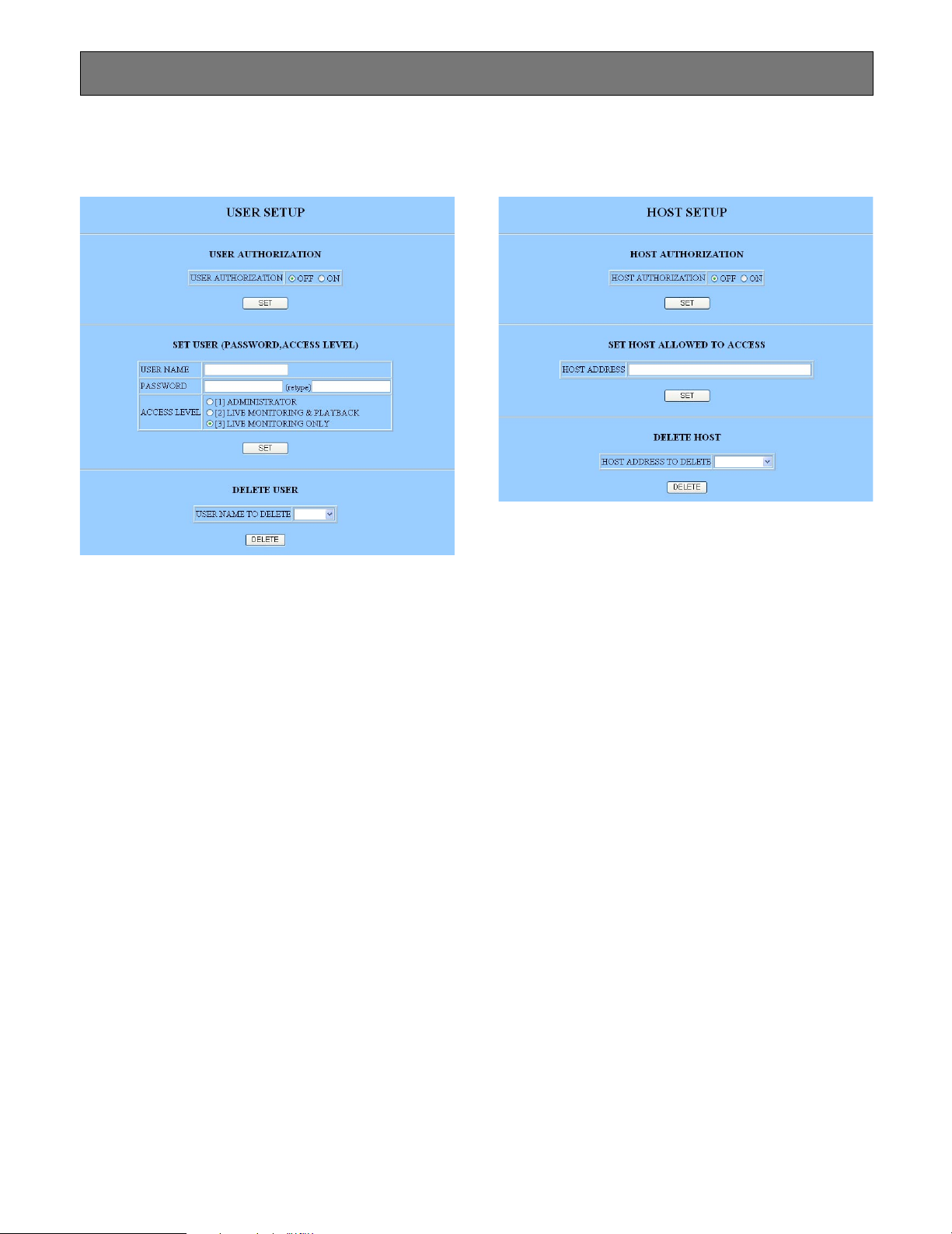
74
■ User Setup (USER SETUP)
A maximum of 16 users can be registered.
8 User Authorization (USER AUTHORIZATION)
OFF: Allows free access.
ON: Verifies the password and access level for a maxi-
mum of sixteen users.
Click the [SET] button.
8 User Name (USER NAME)
Enter from the keyboard. The default is "admin".
8 Password (PASSWORD)
Enter from the keyboard. The default is "admin".
8 Access Level (ACCESS LEVEL)
The default is [1].
[1] ADMINISTRATOR: Allows access to the setup
parameters, live and playback images.
[2] LIVE MONITORING & PLAYBACK: Bans access to
the setup parameters.
[3] LIVE MONITORING ONLY: Allows only monitoring
of live images.
Click the [SET] button when all items have been set properly.
8 Deleting Users (DELETE USER)
Enter or select the user name you wish to erase, and
click the [DELETE] button.
■ Host Setup (HOST SETUP)
A maximum of 8 hosts can be registered.
8 Host Authorization (HOST AUTHORIZATION)
OFF: Allows free access.
ON: Verifies the host address and access level for a
maximum of eight hosts.
Click the [SET] button.
8 Set Host Allowed to Access (SET HOST
ALLOWED TO ACCESS )
HOST ADDRESS: enter from the keyboard.
Click the [SET] button.
8 Deleting Hosts (DELETE HOST)
Enter or select the host address you wish to erase, and
click the [DELETE] button.
Note: Do not enter text lines effective as the HTML tag from
the keyboard to the input columns. Otherwise, the menu
setup using HTML files may malfunction. If this happens, you need to initialize the settings by referring to ■
Initializing described in page 24.
NETWORK CONFIGURATION
Page 75

75
Interval (INTERVAL)
Available times: 1 - 1 440 seconds, 1 - 1 440 min-
utes
Channel to Send (CHANNEL TO SEND)
OFF: Does not send the channel image.
ON: Sends the channel image.
Click the [SET] button when all items have been set properly.
■ FTP Client Setup (FTP CLIENT SETUP)
8 Basic Setup (BASIC SETUP)
Server Address (SERVER ADDRESS)
Enter the server address.
Login User Name (LOGIN USER NAME)
Enter the user name.
Login Password (LOGIN PASSWORD)
Enter the password.
Mode (MODE)
Available modes: SEQUENTIAL, PASSIVE
Click the [SET] button.
8 FTP Send by Periodic Timer (FTP SEND BY
PERIODIC TIMER)
FTP Sending (FTP SENDING)
ON: Sends the channel images at the specified
interval.
OFF: Does not send.
Server Directory (SERVER DIRECTORY)
Enter the directory where you store the image data.
File Name (FILE NAME)
File Name Rule: Date & time basis, Serial number-
ing
Page 76

76
■ Mail Setup (MAIL SETUP)
8 Alarm Mail Setup (ALARM MAIL SETUP)
Sending Mail (SEND MAIL)
OFF: Does not send.
ON: Sends an e-mail to a maximum of four recipi-
ents when an alarm operates.
Attaching Alarm Image (ATTACH ALARM IMAGE)
OFF: Does not attach.
ON: Attaches the image of the alarmed channel to
the mail.
SMTP Server Address (SMTP SERVER ADDRESS)
Enter the SMTP server name or its IP address where
you wish to send a mail. The SMTP server name can be
used only when DNS is set to “AUTO” or “MANUAL”.
Sender Address (FROM ADDRESS)
Enter from the keyboard.
POP3 Authentication (POP3 AUTHENTICATION)
ON: Enables authentication with POP3 before
SMTP.
OFF: Does not use authentication.
POP3 Server Address (POP3 SERVER ADDRESS)
Enter the SMTP server name or its IP address where
you wish to send a mail if POP3 authentication is set to
ON. The server name can be used only when DNS is
set to “AUTO” or “MANUAL”.
User Name (USER NAME)
Enter the user name of the sender’s account.
Password (PASSWORD)
Enter the password of the sender’s account.
Click the [SET] button.
8 Set Mail Address (SET MAIL ADDRESS)
Enter from the keyboard, and click the [SET] button.
A maximum of four addresses can be set.
8 Delete Mail Address (DELETE MAIL ADDRESS)
Enter or select the address you wish to erase,
and click the [DELETE] button.
Note: Use the VIEW.HTML to open the attached image
and view it in the normal aspect. Otherwise, it will
be vertically reduced to half size.
Page 77

77
■ Network Video Setup (NETWORK VIDEO SETUP)
8 Live & Playback Image Setup (LIVE & PLAY
IMAGE SETUP)
Video Rate (VIDEO RATE)
Applicable rates: FAST, MIDDLE, SLOW, VERY
SLOW
Click the [SET] button.
8 Live Sequence Setup (LIVE SEQUENCE SETUP)
Use Sequence (USE SEQUENCE)
OFF: Does not run the sequence.
ON: Runs the sequence.
Auto Skip (AUTO SKIP)
OFF: Displays any step where no video is input as
a blackout screen.
ON: Skips any step where no video is input.
Camera Channel (CAM CH)
Available channels: CH1 - CH8, OFF
Duration (TIME)
Available durations: FAST, MIDDLE, SLOW, VERY
SLOW
Click the [SET] button.
Page 78

78
q Main Control Panel Tab
Opens the main control panel.
w Alarm List Tab
Opens the alarm list.
e Network Status Display
LIVE, LIVE SEQ, PLAY, REV PLAY, >> (FF), << (REW).
PAUSE and AL (playback of alarm record) are displayed.
r Channel Number Display (CH)
The channel number of the image is displayed.
t System Log Display
System errors up to the present are displayed. Refer to
the system log for details.
y Recorder Status Display
REC or REC/ALARM CH# is displayed.
u Time Display
Time and date are displayed.
i Image Display Area
The selected image is displayed.
Notes:
• Buttons and areas from o to !3 will appear only after
the [PLAY] button is clicked.
• An interval between start time and end time of up to 30
minutes is allowed.
• Refer to Appendix for opening the downloaded files.
■ Main Panel
OPERATING WJ-HD220
i
o !1 !2 !3
!4 !5 !6
rtq
w e
!7 !8
!9
@0
y u
!0
@1
@2
@3
Page 79

79
@4 Add Favorite Button (ADD FAVORITE)
Registers the IP address (or URL when using DDNS) to
the favorite of the browser.
@5 Recording Button (REC)
Starts recording.
@6 Recording Stop Button (REC STOP)
Stops recording.
o Start Button (START)
While playing back, clicking this button will specify the
start point for downloading.
!0 Start Time Display Area
Displays the start time of the recorded image that you
are to download.
!1 End Button (END)
While playing back, clicking this button will specify the
end point for downloading.
!2 End Time Display Area
Displays the end time of the recorded image that you
are to download.
!3 Download Button (DOWNLOAD)
Pulls out the time range specified for the image data
from the start to end time.
!4 To the Oldest Frame Button (TO OLDEST)
Jumps the recorded image to the oldest frame of the
record.
!5 Rewind Button (REW)
Rewinds the recorded image on the WJ-HD220 to the
start position.
!6 Reverse Play Button (REV PLAY)
Changes the playback direction backwards.
!7 Play Button (PLAY)
Plays back the recorded image.
!8 Fast Forward Button (FF)
Fast-forwards the recorded image on the WJ-HD220 to
the end position.
!9 To the Latest Frame Button (TO LATEST)
Jumps the recorded image to the latest frame of the
record.
@0 Previous Frame Button (PREV FRAME)
Returns the frame one step to the previous.
@1 Pause Button (PAUSE)
Pauses the playback image.
@2 Stop Button (STOP)
Stops playbacks including REW, PREV FRAME, PAUSE,
PLAY, NEXT FRAME, and FF.
@3 Next Frame Button (NEXT FRAME)
Forwards the frame one step to the next while pausing.
@6@5
@4
Page 80

80
■ Main Control Panel
8 Camera Selection Button (Camera Select)
Click any of the buttons.
The selected camera channel will be displayed in the
image area.
8 Multiscreen Selection Button (Multiscreen Select)
Clicking the button displays the respective multiscreen.
8 Live Sequence Button (LIVE SEQUENCE)
Clicking the [LIVE SEQUENCE] button runs a series of
live images in the preset sequence and for the preset
display time.
8 Alarm Reset Button (ALARM RESET)
The activated alarm event is reset.
8 Time & Date Search Button (TIME&DATE
SEARCH)
Clicking the button will display the time and date search
dialog.
1. Specify the date and time.
2. Click the [OK] button.
The image will be searched, and displayed in the
image area.
Note: Searching may take 18 seconds at worst particu-
larly when the recorder runs simultaneous recording
and playback, and/or when the targeted image is of
small size.
12
8
3
Page 81

81
8 Camera Control View Button (CAMERA
CONTROL VIEW)
The camera control buttons appear on the bottom of the
screen when you click the [CAMERA CONTROL VIEW] button. These buttons enable you to adjust images of combination cameras.
ZOOM (WIDE/TELE) buttons zoom the image in or out.
FOCUS (FAR/NEAR/AUTO) buttons adjust the focus of
the image. When AUTO is clicked, the camera will
adjust the focus by itself.
IRIS (CLOSE/OPEN/RESET) buttons adjust the iris of
the image. When RESET is clicked, the iris will return to
the factory default setting.
AUTO PAN (ON/OFF) buttons allow the camera to pan
endlessly within the preset range.
PRESET allows the camera to turn to the preset position specified by the number.
PAN/TILT Control:
Clicking the desired direction in the image display area
will move the camera if it is mounted on a pan/tilt table.
The image display area is assigned panning/tilting
function with the mouse click. The 25-split (5x5) areas
are invisible, but each represents a moving direction:
up, down, right or left.
The Camera Setup (CAM SETUP) button opens the
camera setup menu and a small panel (CAMERA
SETUP) having nine buttons.
The Up/Down button (↑/↓) moves the cursor up and
down.
The Right/Left button (←/→) moves the cursor right
and left or selects parameters.
The Enter button (ENTER) validates the selection or
opens a lower layer menu.
The Escape button (ESC) returns to a higher layer.
The Reset button (RESET) opens the special menu if
clicked when the cursor is on SPECIAL in the menu.
The All Reset button (ALL RESET) resets all settings
of the camera to the default if clicked when the cursor is
on CAMERA RESET in the special menu.
The Set & Close button (SET & CLOSE) validates the
settings and closes the menu.
Note: Setup items and operating methods may vary
depending on the camera. Refer to the instructions
included with the connected cameras.
LEFT
UP
DOWN
RIGHT
Page 82

82
■ Alarm List
Clicking the alarm list tab on the main control panel opens
the list.
Alarm events are listed with event numbers, dates, channel
numbers, and event types.
Click a line to play back the recorded image of the event.
CH SORT rearranges the listing order to start with the
camera channel you specified. The listing will be sorted
by date and time if ALL is specified.
PREV button returns the list page to previous one.
NEXT button opens the next page.
Alarm List Search button opens the search dialog.
Event types are abbreviated as follows in the list.
TERM: The alarm terminal on the rear of the WJ-HD220
is activated.
VMD: The built-in Video Motion Detector operates.
PC: The recorder received an alarm from a PC.
Specify the month, day, year, and time of the event you
wish to search. If other than ALL is selected, only images of
the specified channel will be displayed.
Click the [OK] button. The dialog box disappears, and the
closest event will be displayed.
Note: Searching may take 18 seconds at worst particularly
when the recorder runs simultaneous recording and
playback, and/or when the targeted image is of small
size.
Page 83

83
■ HTTP Download and Viewing Images
When accessing the WJ-HD220 from the browser, and the
[DOWNLOAD] button is clicked in playback, the image
data and viewer software are downloaded as an "exe" file to
your PC.
Frame No.: Indicates the frame number of the dis-
played image.
Date: Indicates the date when the image was recorded.
Speed: Indicates the playback speed.
OLDEST: Goes to the oldest frame of the record.
REW: Changes the reverse-playback speed by click-
ing.
REV PLAY: Starts playing back in descending order of
the file name.
PLAY: Starts playing back in ascending order of the file
name.
FF: Changes the forward-playback speed by clicking.
LATEST: Goes to the latest frame of the record.
PREV FRAME: Pauses after returning a frame.
PAUSE: Pauses the image display.
NEXT FRAME: Pauses after forwarding a frame.
1. Move the file to an appropriate folder.
2. Double-click the file to expand it to the following.
Image file (.jpg)
index.html
Expanded images can be displayed by executing
"index.html". Using other applications may display the
image vertically reduced to half size.
3. Display "index.html" using the web browser.
SKIP: Jumps the number of the thumbnails.
TOP: Returns to the top page.
PREV: Returns to the previous page.
NEXT: Goes to the next page.
LAST: Jumps to the last page.
Page 84

84
Cannot search alarm image in the list Enter a date that is a little older than the
one you wish to search.
Old image data are overwritten and
cannot be searched.
Old records were discarded.
Specified date may be later.
DISK END MODE is set to CONTINUE.
Over 9 999 of alarm events arose.
Slow image refreshment and/or slow
response to operations
Remote operations are not accepted
while BUSY indicator is lit.
When accessing via the network:
Phenomenon
Power is not turned on.
Error message "HDD ERROR" is displayed on the monitor.
Connect the power cord to AC outlet.
TROUBLESHOOTING
Power cord not properly connected
No disk available
Disconnection of camera, camera
cable, or VIDEO IN BNC.
Ventilation blocked, or failure of cooling
fan
HDD status may have changed, or a
malfunction may have occurred.
Lens cap not removed from the camera, some device is not turned on, or
brightness and contrast of the monitor
are improperly adjusted.
Refer to HDD MAINTENANCE in
Appendix to confirm the HDD status.
Consult your dealer when a malfunction
is found.
Connect the respective camera, cable,
or connector properly.
Remove obstacles, or consult your
dealer for servicing.
Reset the recorder to the factory
defaults (page 24) and enter a new
password.
Check the HDD status referring to HDD
MAINTENANCE. Consult your dealer
when a malfunction is confirmed.
Detach the lens cap, turn on the
device, or adjust the monitor.
Error message "CH n LOSS (n=1-8)" is
displayed on the monitor.
Error message "THERMAL ERROR" is
displayed on the monitor.
Administrator password cannot be
recalled.
DISK MENU appears when turning on
the power.
Camera picture is not displayed on the
monitor.
Cause What to do
Nine-split display does not function. Set it to ALL.QUAD ONLY may be set for MULTI
SELECT MODE.
Setup menus supplied from the Matrix
Switcher are not recorded.
The WJ-HD220 does not record noninterlace video.
Wait until the preceding accesses end.
Wait until the preceding accesses end.
Front panel buttons on the recorder are
being operated, or more than four PCs
access the recorder.
Network is busy.
Intermittent sound reproduction Network is busy.
No click sound desired. Change the setting as follows: Control
Panel → Sound Multimedia → Sound
Tab → Explorer → OFF
Default setting is ON.
Page 85

85
SPECIFICATIONS & APPENDIX
Page 86

86
SPECIFICATIONS
General
Power Source Required: 120 V AC, 60 Hz
Power Consumption: 45 W
Ambient Operating Temperature: +5 °C - +45 °C (41 °F - 113 °F)
Ambient Operating Humidity: Less than 85 %
Dimensions: 420 mm (W) x 44 mm (H) x 350 mm (D)
16-9/16" (W) x 3-7/16" (H) x 13-3/4" (D)
Weight: 5.2 kg (11.4 lbs.)
Input
Video Input: 1.0 V[p-p]/75 Ω Composite video signal with 75 Ω Automatic Termination / Looping
through (x8)
Audio Input: –10 dB 10 kΩ unbalanced, RCA standard jack
Image Process
Compression System: JPEG
Pixel Rate: 720 x 240 (Effective pixels 672 x 224)
Refresh Rate: 30 FPS maximum
Output
Video Output: 1.0 V[p-p]/75 Ω Composite video signal/Looping through (x8)
Video Output Front Panel: 1.0 V[p-p]/75 Ω Composite video signal (x1)
Audio Output: –10 dB 600 Ω unbalanced, RCA standard jack (x1)
Audio Output Front Panel: –10 dB 600 Ω unbalanced, RCA standard jack (x1)
Spot Monitor Output: 1.0 V[p-p]/75 Ω Composite video signal (x1)
Multiscreen Monitor Output: 1.0 V[p-p]/75 Ω Composite video signal (x1)
Control Port
Alarm/Remote Port: 25-pin Full Pitch D-sub connector (x1)
Alarm Input 1-8, Alarm Reset Input, EXT REC Input, Time Adjust Input, Sequence
Input: Low-active, Non-voltage N.O. Contact, ≥100 ms
Alarm Recovery Output 1, Disk End Status Output, Time Adjust Output,
Warning Output, REC Status Output, Sequence Output: Low-active, Open-collector,
24 VDC 100 mA max.
Alarm Output 1, Play Status Output: Low-active, Open-collector,
12 VDC 100 mA max.
Alarm Output 2: High-active, 12 V 4.7 kΩ
Alarm Recovery Output 2: High-active, 12 V DC 220 Ω
RS-485 (PS
•
Data): 6-conductor modular jack (RJ-11)
RS-232C: 9-pin Full Pitch D-sub connector
10/100BASE-TX Port: 10Base-T and 100Base-TX, 8-conductor modular jack (RJ-45)
Protocol Installed: TCP/IP, HTTP, FTP, SMTP, SNMP, DNS, DDNS
Security: Password-protected
Weight and dimensions shown are approximate.
Specifications are subject to change without notice.
Page 87

87
STANDARD ACCESSORIES
Rack Mounting Bracket ............................................................... 2 pcs.
Screw for Rack Mounting Bracket (M3x10) ................................. 6 pcs.
Absorber ...................................................................................... 4 pcs.
Sleeve .......................................................................................... 4 pcs.
Hard Disk Fixing Screw ............................................................... 4 pcs.
Earth Lug ..................................................................................... 1 pc.
Page 88

88
Item
SHIFT
SETUP
FUNCTION
Step playback REW
Alarm record playback
Setup menu display on/off
The top of the oldest record will be
accessed.
Jump to oldest
UP
LR
UP
DOWN
R
WV-CU360
APPENDIX
■ Remote Control from System Controller
A system controller having PS•Data capability can control the WJ-HD220. The table compares operations of the WJ-HD220
and of the system controller WV-CU360. Make certain that the protocol selection for the WJ-HD220 is set to PS
•
Data.
Setup item selection
Parameter selection
Alarm list page turn
Cursor return to setup or
last screen restored
Alarm list display on/off
Alarm event search
WJ-HD220 Note
Button lock is released automatically by opening the setup menu.
Hold down
2 seconds
STOP
SETUP
/ESC
PUSH– PAUSE
SET
/
/
PUSH– PAUSE
SET
/
/
PUSH— PAUSE
SET
/
/
Press
CAM
SET
STOP
SETUP
/ESC
PLAY
CAM
SET
SETUP
FUNCTION
Hold down
2 seconds
DOWN
LR
UP
LR
DOWN
LR
UP
DOWN
LR
MON
ESC
ALM RESET
ALM RECALL
SHIFT
Recording
REC
SETUP
FUNCTION
SHIFT
Playback and recording
stop
Playback stop
Recording stop
STOP
SETUP
/ESC
STOP
SETUP
/ESC
REC STOP
SETUP
FUNCTION
SHIFT
Playback
PLAY
SETUP
FUNCTION
SHIFT
Pause
PUSH– PAUSE
SET
/
/
SETUP
FUNCTION
SHIFT
Step playback FWD
PUSH– PAUSE
SET
/
/
STEP
/
PUSH– PAUSE
SET
/
/
STEP
/
SETUP
FUNCTION
SHIFT
SETUP
FUNCTION
SHIFT
Skip playback FWD
PUSH– PAUSE
SET
/
/
REW/FF
/
SHIFT
SETUP
FUNCTION
Skip playback REW
PUSH– PAUSE
SET
/
/
REW/FF
/
Jump to latest
The top of the latest record will be
accessed.
PUSH– PAUSE
SET
/
/
REW/FF
/
Press
JogDial
SETUP
FUNCTION
SHIFT
PUSH– PAUSE
SET
/
/
REW/FF
/
Press
JogDial
SETUP
FUNCTION
SHIFT
SETUP
FUNCTION
SHIFT
SHIFT
SETUP
FUNCTION
Exclusive use to stop playback
Exclusive use to stop recording
Hold down
2 seconds
Hold down
2 seconds
Press
JogDial
Press
JogDial
Lower layer menu
PUSH– PAUSE
SET
/
/
1/2 1PLAY 2PLAY
3FF 2FF 1FF
1/2 1PLAY 2PLAY
3REW 2REW 1REW
Page 89

89
WJ-HD220
Daylight saving
OFF, INT or EXT selectable
Item WV-CU360 Note
DST
SHIFT
SETUP
FUNCTION
31
Timer REC mode
SHIFT
SETUP
FUNCTION
SHIFT
SETUP
FUNCTION
91
Button lock off
Enter your password.
Button lock on
SHIFT
SETUP
FUNCTION
31
SHIFT
SETUP
FUNCTION
30
Status display on/off
OSD
LOCK
Multiscreen pattern
selection
Multiscreen monitor
MULTISCREEN
SELECT
ZOOM
MULTI SCREEN SELECT
SPOT
MULTI
MON
ESC
Spot monitor
SPOT
MULTI
MON
ESC
Camera selection
18
CAM
SET
Num
Button
PUSH– PAUSE
SET
/
/
Alarm reset
Alarm suspension
Electric zoom in/out
Sequence start
ALM RESET
ALM RECALL
MULTISCREEN
SELECT
ZOOM
ALM
SUSPEND
RESET LOCK
SEQUENCE
SEQUENCE
PATROL
STOP
Enlarged portion can be moved with
the Joystick.
Select a camera to stop the
sequence.
Hold down simultaneously
RESET
EL-ZOOM
+
Display/hide Time&Date
search window while
opening the alarm list
Display Time&Date search
window
Hide Time&Date search
window
Item selection for
Time&Date search window
Time and date selection
for Time&Date search
Implement Time&Date
search
TIME&DATE
SEARCH
TIME&DATE
SEARCH
TIME&DATE
SEARCH
PUSH– PAUSE
SET
/
/
PLAY
UP
DOWN
R
UP
DOWN
LR
SETUP
FUNCTION
CAM
SET
SETUP
FUNCTION
SHIFT
EL-ZOOM
STILL
–
+
MON
ESC
Hold down
2 seconds
Page 90

90
■ RS-232C Communication Protocol
The following pages detail the elements for communication between the Digital Disk Recorder and the personal computer. Be
sure to select RS-232C for PROTOCOL in the COMMUNICATION SETUP window. For BAUD RATE, DATA BIT and PARITY settings, refer to COMMUNICATION SETUP. For cable connection refer to RS-232C CONNECTION.
1. Transmission Command
The PC sends messages to the Recorder in the format shown below. Also refer to the command table shown later.
[p] stands for parameter. Parameters are omitted when there is no need to specify them in the command.
2. Response Command
The Recorder returns messages in reply to the PC’s messages with the following formats.
(1) Reception Command
When the reception was completed successfully, the Recorder sends back the "ACK code 06H" to the PC, and then the
response command below.
Parameters are omitted when the command format includes neither data nor status to send back.
(2) Reception error
The recorder sends back the "NAK code 15H", followed by the parameters shown below. The Recorder then resets the
reception buffer and enters waiting mode for the next message. Parameter "e" identifies the error status.
"e" value 1: Parity error (31H)
2: Framing error (33H)
3: Overrun error (34H)
(3) Parameter error
The Recorder returns the "ACK code 06H", if the transmission code was not processed properly for some reason, followed
by an error code as shown below.
Note: The Recorder returns [ACK] or [NAK] to the PC within 20 ms after the reception of [ETX] in a transmission.
[STX] ERE [ETX]
Code
Code
Code
(02H) ( ) – – – – – – – – – – – – – – – – – ( ) (03H)
[STX] [Transmission Command] : [p1] : [p2] : : [pn] [ETX]
ASCII
(02H) ( ) – – – – – – – – – – – – – – – ( ) (03H)
[STX] [Response Command] : [p1] : [p2] : : [pn] [ETX]
ASCII
[NAK] [e]
ASCII (15H)
Code
(02H) (45H) (03H)ASCII
Page 91

91
● Command Table
Basic Operation
Item Transmission Command (ASCII) Response (ASCII) Parameter (ASCII)
Fast Forward to the end OFF OFF
Pause OPA OPA
Play OPL OPL
Recording ORC ORC
Rewind to the top ORW ORW
Skip&Play Forward OSF:n OSF n=0F Normal speed
n=1F x2 speed
n=2F x5 speed
n=3F x50 speed
n=5F x100 speed
n=0S Normal speed
n=1S 1/2 speed
n=+ Increment
n=– Decrement
Stop OSP:n OSP n=P stops PLAY
n=R stops REC
no parameter stops PLAY and REC
Skip&Play Rewind OSR:n OSR Refer to OSF.
Forward a field OVF OVF
Rewind a field OVR OVR
Camera Selection OCS:ccccc OCS:ccccc ccccc=00001 – 00008 (decimal)
ccccc=+ 1 up
ccccc=– 1 down
Monitor Selection OMS:mmmm OMS:mmmm mmmm=0001 Multi-screen Monitor
mmmm=0002 Spot Monitor
Button Lock MKL:n MKL n=0 Unlock
n=1 Lock
EL-zoom OZM:m OZM:m (m=0-4) m=0 EL-zoom OFF
m=1 EL-zoom ON
m=2 2-fold
m=4 4-fold
m=+ x1 → x2 → x4 → x1
m=– x4 → x2 → x1 → x4
Alarm Control
Item Transmission Command (ASCII) Response (ASCII) Parameter (ASCII)
Alarm Suspension MAD:n MAD:n n=0 Suspension disabled
n=1 Suspension enabled
Alarm History Display OAE:n OAE n=0 Display hides
n=1 Display appears
n=+ Toggle
Alarm Reset OAL:n OAL n=0 Manual reset
n=1 Auto reset
Alarm History Clear OAR OAR
Alarm Picture Search SAS:nnd (:p) SAS n=01 Skip number (fixed)
d=F Search later
d=B Search older
p=L Search and PLAY
p=A Search and PAUSE
Page 92

92
Setup Control
Item Transmission Command (ASCII) Response (ASCII) Parameter (ASCII)
Cursor Moves DCR:n1n2 DCR n1=A Right
n1=C Upward
n1=E Left
n1=G Downward
n2=1 Move a step
n2=2 Move multi steps
n1n2=PD Move to lower layer
n1n2=P+ Move to upper layer
n1n2=P- Turn a newer page
n1n2=PU Turn an older page
Key Lock MKL:n MKL n=0 Lock OFF
n=1 Lock ON
Recording Event MRM:n MRM n=0 Normal recording
Setup n=1 Internal timer recording
n=2 External timer recording
Summer Time Setup MST:n MST n=0 Standard time
n=1 Summer time
Setup MSU:n MSU:n n=0 End setup
n=1 Begin setup
Date&Time Setup TSU:yyyymmddhhnn TSU yyyy=Year
mm=Month
dd=Day
hh=Hour (24-hour system)
nn=Minute
Miscellaneous Control
Item Transmission Command (ASCII) Response (ASCII) Parameter (ASCII)
OSD Show/Hide DIN:n DIN n=+ Toggle
n=0 Hidden
n=1 Shown
Communication Check RCK RCK
Time&Date Search ZTS:yyyymmddhhnnss ZTS yyyy=Year
mm=Month
dd=Day
hh=Hour (24-hour system)
nn=Minute
ss=Second
Time&Date ZTL:n ZTL n=7 Search window displayed
Search Window n=0 Search window hidden
Alarm Log ZTM:n ZTM n=1 Alarm log search displayed
Search Window n=0 Alarm log search hidden
Data Log Control
Item Transmission Command (ASCII) Response (ASCII) Parameter (ASCII)
Log Total Size Inquiry ILB:k ILB:k:bbbbb k=0 Alarm log
bbbbb=00001 to 09999 (in decimal)
Log Erase ILC:n ILC:n n=0 Alarm log
n=1 System log
Log Recorded ILQ:k ILQ:k:bbbbb:ddddd:(:E) k=0 Alarm log
Size Inquiry bbbbb=00001 - 09999 (Oldest log)
ddddd=00001 - 09999 (Size of log)
E=Overwrite
Log Readout ILR:k:sssss:mmmmm ILR:k:<log data s1>s1 k=0 Alarm log
<log data s2>s2 sssss=00001 - 09999 Start Address
<log data sn>F mmmmm=00001-00100
Decimal # of log
<log data sn>=yymmddhhnnss
sn=0-9 and F Cyclic number
(F is put at data end)
Page 93

93
Media Control
Item Transmission Command (ASCII) Response (ASCII) Parameter (ASCII)
Disk End Notice Setup MDE:n MDE n=0 End is not notified
n=1 End is notified
Disk End Notice HDE
Inquiry
Item Transmission Command (ASCII) Response (ASCII) Parameter (ASCII)
Remaining Size QHR QHR:nnn nnn=000-100 Decimal %
Inquiry
ID Inquiry QID QID:WJ-HD220
Key Lock Status QKM QKM:n n=0 Lock OFF
Inquiry n=1 Lock ON
Alarm Info Inquiry QLD:n QLD:n (Alarm Information) In Transmission command:
n=0 Event report
n=1 Date&time report
In Response command:
n=0 No alarm event
n=1 Alarm has been reset
n=2 Alarm activated
k=0 VMD
n=2 PC alarm
Alarm Information:
k1:y1y1m1m1d1d1h1h1n1n1s1s1:
k2:y2y2m2m2d2d2h2h2n2n2s2s...
Status Inquiry QSR
QSR: [status1]:[status2]:…[status13]
mad:1 Alarm suppression On
mad:0 Alarm suppression Off
mkl:1 Button locked
mkl:0 Button unlocked
msu:1 Setup operation
msu:0 Normal operation
oms:0001 Multiscreen monitor
oms:
0002 Spot
monitor
ocs:ccccc
ccccc= Camera # (00001 - 00008)
otc:0 4-split screen
otc:2 9-split screen
oqt:01n n=F Sequence running
n=P Sequence pausing
oae:1 Alarm log displayed
oae:0 Alarm log Hidden
orc Recording
osp:R Pause while recording
opl Playback
opa Pause
osf:0F - 5F Fast playback
0F= x1, 1F≈ x2, 2F≈ x5, 3F≈ x50
4F=Not applicable, 5F≈ x100
osf:0S - 1S Slow playback
0S= 1/1, 1S≈ 1/2
osr:0F - 5F Reverse fast playback
0F= x1, 1F≈ x2, 2F≈ x5, 3F≈ x50
4F=Not applicable, 5F≈ x100
osr:0S - 1S Reverse slow playback
0S= 1/1, 1S≈ 1/2
osp:P Stop
ztl:7 Search screen displayed
ztl:0 Search screen hidden
ztm:1 Alarm log search displayed
ztm:0 Alarm log search hidden
Software Version Inquiry QRV
QRV: (Version numbers)
System version number
Page 94

94
■ HDD Maintenance
● When to Maintain HDD
HDD maintenance is required in the following cases.
• When FULL indicator lights up
• When ERROR indicator lights up
• When an optional hard disk is added
• When you wish to format the HDD or to remove link
• When HDD reaches its life time (around 30 000 hours,
displayed in the SYSTEM INFO window)
2 seconds later
DISK MENU
NO.1:XXX.XXGB
NO.2:XXX.XXGB
REMOVE LINK
→
SET
→
HDD FORMAT → SET
→
RESTART → SET
→
SYSTEM CHECK
HDD ERROR
SYSTEM CHECK DONE!
TO OPEN DISK MENU
PUSH STOP KEY
Power-on
System check
Press the STOP button.
Available disk?
System composition changed
or
suspicious HDD?
Camera picture
Needed formatting
or something?
Turn off the power.
Install new HDD.
No
No
No
Yes
Yes
Yes
HDD check
HDD CHECK
● Who to Maintain HDD
Caution: Addition, replacement, and other HDD main-
tenance should be performed by qualified service
personnel.
● Power-on Procedures
After power-on, the recorder confirms the HDD status and displays corresponding messages on the monitor.
Page 95

95
● When Error Indicator is Lit
Refer to your dealer for servicing when this happens.
8 HDD Check
The recorder checks the hard disk when the recorder is
turned on, or when the HDD CHECK time specified in
the menu setup comes during operation.
The recorder warns you of any error detected as follows.
Error indicator blinks.
Warning Out terminal on the rear panel turns active.
"HDD ERROR" will appear when there is no disk installed in
the recorder.
When this happens, turn off the power. New disk(s) should
be installed on the recorder, referring to INSTALLATION.
8 When Error Detected
1. Turn off the recorder, and turn it on again. It will perform
as follows.
DISK MENU is displayed.
Error indicator blinks.
Buzzer beeps every 5 seconds.
2. Press any buttons other than [STOP] to stop the indicator blinking and buzzer beep.
3. See DISK MENU on the next page for further operations.
● When Full Indicator is Lit (Resetting
Disk End)
8 FULL Indicator
The FULL indicator will light up when STOP is set to
DISK END MODE, provided that the disk space nears
the end.
To reset it, do the following.
8 DISK END Setup
1. Hold down the [STOP] button for 2 seconds to open the
MAIN MENU.
2. Select SYSTEM SETUP, and press the JogDial to open
the SYSTEM SETUP menu.
3. Move the cursor to DISK END MODE, and rotate the
JogDial to select CONTINUE. Then press the JogDial.
STOP: Stops recording at the disk end.
CONTINUE: Overwrites from the start of the disk.
4. Press the [STOP] button to return to the MAIN MENU.
5. Hold down the [STOP] button for 2 seconds to return to
normal operations.
The recorder starts operating in continuous mode up to
the disk end.
If you wish the recorder to revert to STOP for DISK END
MODE, repeat above steps 1 through 5, but select
STOP in step 3.
WJ-HD220 MAIN MENU
TIMER OFF
REC SETUPO
EXT REC SETUPO
DISPLAY SETUPO
SYSTEM SETUPO
ALARM SETUPO
COMMUNICATION SETUPO
SWITCHER SETUPO
SYSTEM INFORMATIONO
LANGUAGE ENGLISH
HDD ERROR
SYSTEM SETUP (1 OF 2)
PASSWORD LOCK OFF
ALL→ *****
OPERATION→ *****
KEYLOCK BUZZ OFF
SKIP ALM-RECALL 5PAGE
SIMUL REC&PLAY ON
ALTER DETECT OFF
DISK END MODE CONTINUE
DISK END BUZZ ON
Page 96

96
You can implement any of the following operations as necessary.
REMOVE LINK: Logically removes the HDD link.
HDD FORMAT: Formats the HDD.
RESTART: Closes the menu, and restarts the recorder.
The menu can also be displayed manually when you need to format the HDD or remove the logical link.
1. Turn off the power of the recorder once, and turn it on again.
The multiscreen monitor displays the message "SYSTEM CHECK DONE! TO OPEN DISK MENU, PUSH STOP KEY".
2. Press the [STOP] button.
The DISK MENU opens.
3. Select REMOVE LINK, HDD FORMAT, or RESTART.
Auto-remove
When no button is pressed for one minute after opening the DISK MENU, the recorder will logically remove a disk that meets
any of the conditions below.
• An HDD has been categorized as " * ", "LOST", or "ERR".
• Restart was repeated 3 times due to writing error.
● DISK MENU
8 Disk Menu
The menu appears if the hard disk error is found during
power-up.
The buzzer beeps every 5 seconds, and the ERROR
indicator turns off.
Press any button other than [STOP] to mute the buzzer
beep.
The hard disk status and required operations are shown in the table.
Abbreviation Status Required
–
Format, remove link ,or replace HDD
if erred even after formatting.
Note
WR1 or WR2 appears in SYSTEM LOG
when indicating a writing error.
Normal status
Writing error
Same as above.LOST or * status was left for
one minute.
All existing HDD have been previously
used in another WJ-HD220.
Restart or FormatAwaiting format
HDD is removed without executing
REMOVE LINK command.
Remove link, or add a new HDD.HDD physically removed
FormatHDD added, and awaiting
format
Capacity
ERR
*
LOST
ADD
REMOVE LINK command has been
previously carried out.
Previous time and this time,
HDD physically or logically
removed
–
DISK MENU
NO.1:XXX.XXGB
NO.2:XXX.XXGB
REMOVE LINK SET
HDD FORMAT SET
RESTART SET
Hard Disk Status
→
→
→
Operation
Page 97

97
8 Formatting HDD (HDD FORMAT)
This command initializes the HDD format and is applicable to HDDs of *, ERR, or ADD status.
Caution: Formatting is an irreversible procedure. We
strongly recommend that, before formatting, you
either save the recorded data into the server via the
network, or you save the data on VCR tapes via the
REC OUT terminal.
1. Display the DISK MENU window.
2. Move the cursor to HDD FORMAT, and press the
JogDial.
The password prompt appears.
3. Enter the ALL password using the CAM SELECT buttons 1 through 8. The default password is 12345.
Access to the HDD will be possible if the correct password is entered.
4. Rotate the JogDial to select the HDD you wish to format, and press the JogDial.
1: Formats HDD #1.
2: Formats HDD #2.
ALL: Formats HDD #1 and #2.
The window prompts you to confirm whether the HDD is
to be formatted or not.
8 Removing Logical Link (REMOVE LINK)
This command logically disconnects the faulty HDD
from the recorder and is applicable to an HDD of *,
ERR, or LOST status.
You may use this command before physically removing
the faulty HDD, or when you continue to operate the
system after logically removing the faulty HDD.
1. Display the DISK MENU window.
2. Move the cursor to REMOVE LINK.
3. Select YES with the JogDial, and press the JogDial.
YES: Logically removes the faulty HDD.
When YES is selected, the display YES will turn to SET
DONE for 5 seconds, and the window will return to normal operation.
When the [STOP] button is pressed, the window returns
to that of step 1.
Select RESTART to return to normal operation.
Note: The window of step 1 appears following the
"ERROR" message when this command is used
under the conditions below:
A single HDD or no HDD exists.
Both HDDs malfunction.
DISK MENU
NO.1:XXX.XXGB
NO.2:XXX.XXGB
REMOVE LINK SET
HDD FORMAT SET
RESTART SET
→
→
→
REMOVE LINK YES
→
DISK MENU
NO.1:XXX.XXGB
NO.2:XXX.XXGB
REMOVE LINK SET
HDD FORMAT SET
RESTART SET
→
→
→
PASSWORD
REMOVE LINK SET DONE!
PASSWORD
*****
Page 98

98
5. Select YES or NO rotating the JogDial, and press the
JogDial.
YES: Carries out formatting. Wait until the process
ends.
When YES is selected, the display will turn to NOW
FORMATTING. It will change to HDD FORMAT → SET
DONE when formatting is completed.
When the [STOP] button is pressed, the window returns
to that of step 1.
Select RESTART to return to normal operation.
8 Restarting (RESTART)
This command closes the DISK MENU, and returns to
normal operation.
1. Display the DISK MENU.
2. Move the cursor to RESTART.
3. Press the JogDial.
4. Rotate the JogDial to select a restarting parameter.
YES: Escapes from the DISK MENU, and enters normal
operation.
PLAY ONLY: Enters a special mode that prohibits
recording, but allows playback.
Notes:
• The PLAY ONLY mode can be utilized when you
verify a transplanted HDD removed from another
disk recorder that malfunctioned.
• In normal operation after selecting the PLAY ONLY
mode, "STOP (PO)" appears in the status display
while camera pictures are displayed, but not in
playback. "PO" stands for PLAY ONLY.
5. Press the JogDial to execute the selection, or press the
[STOP] button to return to the above step 1.
A message "SET DONE!" appears, and the recorder
restarts.
Notes:
• Follow the procedures described above when the DISK
MENU appears again after restarting. This happens
when the settings have been changed.
• To cancel the PLAY ONLY mode, follow these procedures described above and select YES for RESTART.
NOW FORMATTING
HDD FORMAT SET DONE!
RESTART SET DONE
DISK MENU
NO.1:XXX.XXGB
NO.2:XXX.XXGB
REMOVE LINK SET
HDD FORMAT SET
RESTART SET
RESTART SET
RESTART NO
→
→
→
→
Page 99

99
■ Mail Contents
The recorder sends e-mails to the specified addresses
when SEND MAIL is set to ON. An e-mail contains the following information.
● Alarm Notice Mail
A JPEG image file with an HTML file will be sent when specified to attach.
WJ-HD220 (Sender IP Address) STATUS REPORT
DATE: Jan31.03 00:00:00
PORT: nCH
URL: http://Sender IP address:Port Number/
Note: URL is displayed when DDNS is applied. The port number except 80 is displayed.
● Error Notice Mail
WJ-HD220 (Sender IP Address) STATUS REPORT
DATE: Jan31.03 00:00:00
STATUS: Abbreviated Cause
URL: http://Sender IP address:Port Number/
Note: URL is displayed when DDNS is applied. The port number except 80 is displayed.
Abbreviation Cause
THERMAL ERROR Out of operating temperature range
DISK WARNING OF "DiskType" S.M.A.R.T. detected error on HDD.
"DiskType"
MASTER: Error on HDD1
SLAVE: Error on HDD2
REMAINS HDD CAPACITY **% Warning on remaining HDD capacity (**%).
An e-mail is sent when the remaining capacity drops below
the preset value for HDD FULL.
Until DISK END status is rest, an e-mail is sent every time the
capacity is reduced by 1 %. A remaining capacity of less
than 1 % will be rounded to 0 %.
HDD IS FULL Resetting the DISK END status is needed to resume recording.
"DiskType" IS LOGICALLY REMOVED The type of disk has failed and has been logically removed.
"DiskType"
MASTER: Error on HDD1
SLAVE: Error on HDD2
VIDEO LOSS nCH Video loss is detected on channel "n".
Repair the camera or cable disconnection.
NO "Type" RECORD DUE TO FULL DISK Alarm-recording triggered by "Type" was not possible
due to shortage of the space.
"Type"
VMD TRIGGERED: VMD alarm
TERMINAL TRIGGERED: Terminal alarm
PC TRIGGERED: PC alarm
UNDEFINED ERROR Errors other than the above have occurred
Page 100

100
■ Network Security
● WJ-HD220 Security Function
Host/User Authentication
Access can be limited by setting the authentication function to ON in the menu setup.
Note: Be sure to change the password from the default setting "admin" to your own.
Changing the HTTP Port Number
Changing the port number will limit unauthorized accesses such as port scanning.
● For More Security
Using Routers
Authentication is doubled by use of routers: dividing into subnet, and verifying IP addresses by the
recorder and the routers.
Using Fire Wall
A fire wall will apply packet filtering and protocol filtering to secure the recorder against
unauthorized access.
IP Address: 192.168.1.1
Subnetmask: 255.255.255.0
PC
Router
IP Address: 192.168.1.100
Subnetmask: 255.255.255.0
Default Gateway: 192.168.1.1
Global IP
Global IP
WAN
IP Address: 192.168.0.1
Subnetmask: 255.255.255.0
Digital Disk Recorder
IP Address: 192.168.0.10
Subnetmask: 255.255.255.0
Router
Default Gateway: 192.168.0.1
ALARM
SUSPEND
OPERATE
RESET
CAMERA SELECT
SPOT
DST
TIMER
MULTI
REMOTE
1526374
MULTISCREEN
OSD
LOCK
SEQUENCE
SELECT
8
ZOOM
SET
PUSH– PAUSE
HDD
STOP
PLAY
REC STOP
REC
SETUP
/ESC
FULL
ALARM
TIME&DATE
SERCH
SEARCH
ALARM
ERROR
RECALL
PLAY MODE SELECT
Digital Disk Recorder WJ-HD220
IP Address: 192.168.1.1
Subnetmask: 255.255.255.0
Router
PC
IP Address: 192.168.1.100
Subnetmask: 255.255.255.0
Default Gateway: 192.168.1.1
WAN
IP Address: 192.168.0.1
Subnetmask: 255.255.255.0
Digital Disk Recorder
IP Address: 192.168.0.10
Subnetmask: 255.255.255.0
Default Gateway: 192.168.0.1
TIMER
ALARM
REMOTE
SUSPEND
OPERATE
RESET
LOCK
Router
Fire Wall
Switching hub
SET
CAMERA SELECT
SPOT
DST
MULTI
1526374
MULTISCREEN
OSD
SEQUENCE
SELECT
8
ZOOM
PUSH– PAUSE
HDD
STOP
PLAY
REC STOP
REC
SETUP
/ESC
FULL
ALARM
TIME&DATE
SERCH
SEARCH
ALARM
ERROR
RECALL
PLAY MODE SELECT
Digital Disk Recorder WJ-HD220
 Loading...