

Page 1

Digital Disk Recorder
Digital Disk Recorder WJ-HD
OPERATE
TIMER
HDD
ALARM
SUSPEND
SUMMER
TIME
FULL
LOCK
MEMORY CARD
DISPLAY SELECT
STOP
LCD CONTRAST
PLAY
SETUP/ESC
REC
PUSH
PAUSE
SET
ALARM SEARCH
STEP
REW/FF
MODE SELECT
/
/
/
/
Operating Instructions
Model No. WJ-HD100
ENGLISHDEUTSCH
FRANÇAIS
please read these instructions carefully and save this manual for future use.
Before attempting to connect or operate this product,
ESPAÑOL
Page 2
ENGLISH VERSION
We declare under our sole responsibility that the product to which this
declaration relates is in conformity with the standards or other normative
documents following the provisions of Directives EEC/73/23 and
EEC/89/336.
Noi dichiariamo sotto nostra esclusiva responsabilità che il prodotto a
cui si riferisce la presente dichiarazione risulta conforme ai seguenti
standard o altri documenti normativi conformi alle disposizioni delle
direttive CEE/73/23 e CEE/89/336.
Wij verklaren als enige aansprakelijke, dat het product waarop deze
verklaring betrekking heeft, voldoet aan de volgende normen of andere
normatieve documenten, overeenkomstig de bepalingen van Richtlijnen
73/23/EEC en 89/336/EEC.
Vi erklærer os eneansvarlige for, at dette produkt, som denne deklaration omhandler, er i overensstemmelse med standarder eller andre normative dokumenter i følge bestemmelserne i direktivene 73/23/EEC og
89/336/EEC.
CAUTION
RISK OF ELECTRIC SHOCK
DO NOT OPEN
CAUTION: TO REDUCE THE RISK OF ELECTRIC SHOCK,
DO NOT REMOVE COVER (OR BACK).
NO USER-SERVICEABLE PARTS INSIDE.
REFER SERVICING TO QUALIFIED SERVICE PERSONNEL.
The lightning flash with arrowhead symbol,
within an equilateral triangle, is interned to
alert the user to the presence of uninsulated
"dangerous voltage" within the product's
enclosure that may be of sufficient magnitude to constitute a risk of electric shock to
persons.
The exclamation point within an equilateral
triangle is intended to alert the user to the
presence of important operating and maintenance (servicing) instructions in the literature accompanying the appliance.
The serial number of this product may be found on the bottom of the unit.
You should note the serial number of this unit in the space
provided and retain this book as a permanent record of your
purchase to aid identification in the event of theft.
Model No. WJ-HD100
Serial No.
Vi deklarerar härmed värt fulla ansvar för att den produkt till vilken
denna deklaration hänvisar är i överensstämmelse med standarddokument, eller andra normativa dokument som framställs i EEC-direktiv nr.
73/23 och 89/336.
Ilmoitamme yksinomaisella vastuullamme, että tuote, jota tämä ilmoitus
koskee, noudattaa seuraavia standardeja tai muita ohjeellisia asiakirjoja,
jotka noudattavat direktiivien 73/23/EEC ja 89/336/EE. säädöksiä.
Vi erklærer oss alene ansvarlige for at produktet som denne erklæringen
gjelder for, er i overensstemmelse med følgende normer eller andre normgivende dokumenter som følger bestemmelsene i direktivene
73/23/EEC og 89/336/EEC.
Caution:
Before attempting to connect or operate this product,
please read the label on the bottom.
For U.K.
FOR YOUR SAFETY PLEASE READ THE FOLLOWING TEXT CAREFULLY.
This appliance is supplied with a moulded three pin mains plug for your
safety and convenience.
A 13 amp fuse is fitted in this plug.
Should the fuse need to be replaced please ensure that the replacement
fuse has a rating of 13 amp and that it is approved by ASTA or BSI to
BS1362.
Check for the ASTA mark
fuse.
If the plug contains a removable fuse cover you must ensure that it is
refitted when the fuse is replaced.
If you lose the fuse cover the plug must not be used until a replacement
cover is obtained.
A replacement fuse cover can be purchased from your local Panasonic
Dealer.
IF THE FITTED MOULDED PLUG IS UNSUITABLE FOR THE SOCKET OUTLET IN YOUR HOME THEN THE FUSE SHOULD BE
REMOVED AND THE PLUG CUT OFF AND DISPOSED OF SAFELY.
THERE IS A DANGER OF SEVERE ELECTRICAL SHOCK IF THE
CUT OFF PLUG IS INSERTED INTO ANY 13 AMP SOCKET.
If a new plug is to be fitted please observe the wiring code as shown
below.
If in any doubt please consult a qualified electrician.
WARNING: This apparatus must be earthed.
The wires in this mains lead are coloured in accordance with the following code.
As the colours of the wire in the mains lead of this appliance may not
correspond with the coloured markings identifying the terminals in your
plug, proceed as follows.
The wire which is coloured green-and-yellow must be connected to
the terminal in the plug which is marked with the letter E or by the earth
symbol
The wire which is coloured blue must be connected to the terminal in
the plug which is marked with the letter N or coloured black.
The wire which is coloured brown must be connected to the terminal
in the plug which is marked with the letter L or coloured red.
How to replace the fuse
Open the fuse compartment with
a screwdriver and replace the fuse
and fuse cover.
Green-and-yellow: Earth
Blue: Neutral
Brown: Live
I or coloured green or green-and-yellow.
Hor the BSI mark Gon the body of the
IMPORTANT
FUSE
2
WARNING:
To reduce the risk of fire or electric shock, do not expose this appliance to rain or moisture.
Page 3

CONTENTS
PREFACE .................................................................................................................. 4
FEATURES ................................................................................................................ 4
PRECAUTIONS ......................................................................................................... 5
MAJOR OPERATING CONTROLS AND THEIR FUNCTIONS .................................. 6
■ Front View ......................................................................................................... 6
■ Rear View .......................................................................................................... 7
INSTALLATION ......................................................................................................... 9
■ Mounting in the Rack ........................................................................................ 9
CONNECTION .......................................................................................................... 10
■ Basic Connection ............................................................................................. 10
■ Connections with PS
■ Series Connection ............................................................................................ 12
■ Alarm Terminal Connection .............................................................................. 13
■ RS-232C Connection ........................................................................................ 13
•
■ PS
Data Connection ......................................................................................... 13
■ Mode Switch Setting ......................................................................................... 14
SETUP PROCEDURES ............................................................................................. 15
■ Prior to Setup .................................................................................................... 15
■ Initializing .......................................................................................................... 18
■ WJ-HD100 SETUP MENU ................................................................................. 19
■ SYSTEM SETUP ................................................................................................ 21
■ REC SETUP ...................................................................................................... 24
■ ALARM SETUP ................................................................................................. 27
■ INTERNAL TIMER REC ..................................................................................... 29
■ COMMUNICATION SETUP ............................................................................... 30
■ SYSTEM INFORMATION .................................................................................. 31
OPERATING PROCEDURES .................................................................................... 32
■ Sequence of LCD Displays (in operation) ........................................................ 32
■ Recording ......................................................................................................... 34
■ Playback ........................................................................................................... 35
■ Alarm Operation ................................................................................................ 38
■ Copy to CompactFlash Card ............................................................................ 39
■ Lock/Unlock Buttons ......................................................................................... 41
TROUBLESHOOTING .............................................................................................. 42
SPECIFICATIONS ..................................................................................................... 43
APPENDIX ................................................................................................................ 44
■ Remote Control From System Controller .......................................................... 44
■ SERIES RECORDING ....................................................................................... 45
■ Communication Protocol .................................................................................. 47
•
Data Equipment ............................................................. 11
ENGLISH
3
The model numbers listed in this Operating Instructions have no suffixed attached to it.
Page 4

PREF ACE
The Digital Disk Recorder WJ-HD100 records information
on a large capacity hard disk and is designed for use within
a surveillance system. It records up to 960 hours of surveillance images (in long-time mode) on a field basis. There
are 10 selectable picture quality levels and the field rate
can be selected as well. Besides recording and playback,
FEATURES
• High quality still picture
Still pictures are recorded on the disk after compression in the JPEG image file format.
• No need to replace a video tape
Thanks to the large disk capacity, there is no more
need to replace the recording medium. The recording
time can be extended to 16 times that of a single unit
by operating multiple units in series.
• Easy access to the desired record
Time & Date search and alarm event search make
retrieval easy.
the WJ-HD100 features versatile interfaces with alarm sensors, a CompactFlash card, RS-232C devices and PS
equipment. Interactive menus are provided for system
setup, recording setup, alarm setup and so forth.
• Various alarm modes
A different picture quality can be selected for alarm
recording and for ordinary recording.
A buzzer can be set up to beep when an alarm input is
received.
Besides the physically connected sensors, a built-in
motion detector can be set up to generate alarm.
• Remote control
An RS-232C port enables the recorder to communicate
with a personal computer or other RS-232C devices.
A modular terminal is equipped for communication with
•
PS
Data devices in the RS-485 chain.
•
Data
• CompactFlash card slot
Pictures stored on the disk can be copied to a
CompactFlash card in the card slot to browse through
them on a personal computer.
TRADEMARKS
SanDisk and CompactFlash are trademarks of SanDisk Corporation.
Microsoft and Windows are either registered trademarks or trademarks of Microsoft Corporation in the United States and/or other countries.
4
Page 5

PRECAUTIONS
• Refer all work related to the installation of this product
to qualified service personnel or system installers.
• Avoid condensation on the surface of the hard disk.
Wait until the dew evaporates if any of the following
case takes place.
The recorder is moved to a place significantly different in temperature or humidity.
The recorder is moved out of an air-conditioned
room.
The recorder is placed in an extremely humid
place.
The recorder is placed in a room where a heater
has just been turned on.
• Consumable parts
Contact your dealer for replacement of the following
parts when the time comes:
Built-in hard disk needs replacement after around
30 000 hours of operation.
Cooling fan also needs replacement after around
30 000 hours of operation.
Backup battery has a lifetime of around five (5)
years in an ordinary environment.
• We recommend that you note down your settings and
retain them. Power or battery failure may erase settings
you entered.
• Do not expose the appliance to water or moisture, nor
try to operate it in wet areas.
• Do not use strong or abrasive detergents when cleaning the appliance body.
Use a dry cloth to clean the appliance when it is dirty.
When the dirt is hard to remove, use a mild detergent
and wipe gently.
• Do not operate the appliance beyond its specified temperature, humidity or power source ratings.
Do not use the appliance in an extreme environment
where high temperature or high humidity exists. Use the
appliance at temperatures within +5°C to +45°C (41°F
to 113°F) and a humidity below 90 %.
The input power source for this appliance is 220 - 240 V
AC 50 Hz.
• Do not block the ventilation opening or slots on the
cover.
To prevent the appliance from overheating, place it at
least 5 cm (2 inches) away from the wall.
• Do not drop metallic parts through slots.
This could permanently damage the appliance. Turn
the power off immediately and contact qualified service
personnel for service.
• Handle the appliance with care.
Do not strike or shake, as this may damage the appliance.
• Fully charge up the backup battery.
Keep the appliance turned on for at least 48 hours to
recharge the backup battery. This procedure is necessary when using the appliance for the first time or after
it has been unplugged for a long time from the AC outlet. Insufficient charging of the battery may cause erasure of settings if the AC power supply should fail.
5
Page 6
MAJOR OPERATING CONTROLS AND THEIR FUNCTIONS
OPERATE
TIMER HDD
ALARM
SUSPEND
SUMMER
TIME
FULL
LOCK
MEMORY CARD
DISPLAY SELECT
STOP
PLAY REC
PUSH– PAUSE
SET
ALARM SEARCH STEP REW/FF
PLAY MODE SELECT
//
/
/
SETUP/ESC
q
w e
r
t
y
u
i
o
!0
!1
!2
!3 !4
!5 !6 !7 !8
LCD CONTRAST
Digital Disk Recorder WJ-HD
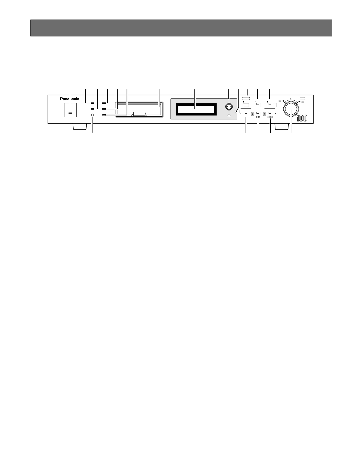
■ Front View
q Operate Indicator [OPERATE]
Lights while the power switch on the rear is turned on.
w Timer Record Reservation Indicator [TIMER]
Lights when a reservation is made for internal timer
recording.
e Alarm Suspension Indicator [ALARM SUSPEND]
Lights when an alarm is activated while alarm suspension is selected. The alarm will be logged in the event
history, but recording is suspended and the buzzer will
not sound.
r Summer Time Button [SUMMER TIME]
Press the recessed button with a pin to advance the
internal clock by one hour to summer time, or to set it
back to normal time. While the clock is on summer time,
an asterisk * appears in the time and date display on
the LCD and on the video monitor.
t HDD Access Indicator [HDD]
Lights while the disk is being accessed.
y Full Indicator [FULL]
Blinks when the remaining disk capacity reaches the
preset value, and lights when the disk is full.
u Lock Indicator [LOCK]
Lights when buttons and JogDial on the front panel are
disabled.
i Memory Card Slot [MEMORY CARD]
Open the lid to insert the CompactFlash card into the
slot or to remove it from the slot. The card is used to
store still pictures for browsing through them on a personal computer.
o LCD
Displays setup parameters while working with menus,
or the operating status while recording or playing back.
!0 LCD Button [DISPLAY SELECT]
There are five positions to press; up, down, left, right
and centre. Press the appropriate positions to select a
parameter on the LCD.
!1 LCD Contrast Control [LCD CONTRAST]
Adjust the LCD contrast by rotating the control knob
with a small screw driver.
!2 Stop and Setup/ Escape Button
[■ STOP] [SETUP/ESC]
Pressing this button in any mode other than menu setup
stops recording or playback.
Holding down this button for 2 seconds calls up setup
menus or escapes from the setup.
Press this button to go back one step to the previous
selection in the setup menu.
!3 Play Button [5 PLAY]
Press this button to start playback. The LED lights while
playing back, and blinks while pausing or searching.
!4 Recording Button [● REC]
Press this button to start recording. The LED lights while
recording, and blinks while alarm recording.
!5 to !7 are PLAY MODE SELECT buttons that also specify
the JogDial performance in the selected play mode. See
pages 35, 36 and 37 for further details.
!5 Alarm Search Button [ALARM SEARCH]
Press this button to search for a desired record in the
alarm log. The LED lights in the alarm search mode.
!6 Step and Down Button [STEP A
❚❚/❚❚
B] [C]
Press this button to start playing back still pictures field
by field. The LED lights in the step playback mode.
Press this button to move the cursor downward in a
setup menu on the monitor.
6
Page 7
!7 REW/FF and Up Button [REW/FF 1/2] [D]
SIGNAL GND
ALARM
SERIES
RECORD
TIME
ADJUST
REMOTE
MODEDATARS-232CVIDEO
OUT
IN
OUT
IN
AUDIO
MONITOR OUT
(PLAY)
CAMERA
SW OUT
G
G
G
POWER
ON
OFF
JOG-CLICK
JOG-LEFT
JOG-RIGHT
ALARM SEARCH
STEP
REW/FF
STOP/SETUP
PLAY
REC
OUT
PLAY OUT
REC OUT
AUTO OFF OUT
DISK END OUT
IN
OUTINRECALL
(EXT REC)
OUT
RECOVER OUT
RESET IN
IN
@2
@1 @3 @4
@5 #0 #1 #2 #3 #4
@6 @7 @8 @9 #5 #6 #7
#8
Press this button to rewind or fast-forward the recorded
field. The LED lights in the REW/FF mode.
Press this button to move the cursor upward in a setup
menu on the monitor.
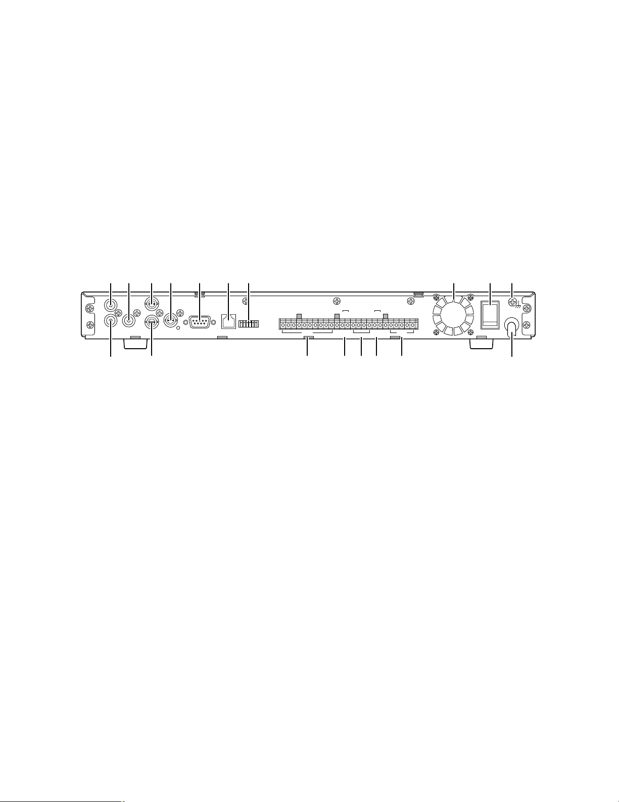
■ Rear View
!8 JogDial [PUSH –
❚❚
PAUSE] [SET]
Press the JogDial to pause or restart playback.
Rotate the JogDial to access the desired field while
rewinding, fast-forward and playing back.
Rotate the JogDial to search the oldest picture recorded on the disk for playing back in chronological order.
Rotate the JogDial to select a parameter in a setup
menu.
Press the JogDial to enter the selected parameter and
move the cursor to the next position on a setup menu.
Hold down the JogDial to copy still pictures to the
CompactFlash card.
@1 Audio Input Connector [AUDIO IN]
RCA standard jack accepts an unbalanced –10 dB and
10 kΩ line input audio signal supplied from an external
device.
@2 Audio Output Connector [AUDIO OUT]
RCA standard jack supplies an unbalanced –10 dB and
600 Ω line output audio signal to an external device.
@3 Camera Switching Output Connector [CAMERA SW
OUT]
This jack is for connecting an external device such as a
video multiplexer receiving multiple camera inputs. The
switching signal supplied makes the connected device
switch from one camera to the other. Use this terminal
only when the recording field rate is lower than 10 fps.
@4 Video Input Connector [VIDEO IN]
This BNC accepts a video signal supplied from a camera or video multiplexer. A 75 Ω termination is made
unless the video output terminal is connected.
@5 Video Output Connector [VIDEO OUT]
This BNC supplies a video signal looped through the
video input terminal. Connect with a video monitor to
check the input picture, or the next WJ-HD100 in a
SERIES connection.
@6 Monitor Output Connector [MONITOR OUT (PLAY)]
This BNC supplies playback pictures stored on the
hard disk, or setup windows. Connect with a video
monitor.
@7 RS-232C Port [RS-232C]
Through this 9-pin D-Sub connector the digital disk
recorder communicates with the personal computer.
Use a reverse type cable for connection with the personal computer. Protocol and commands are described
in APPENDIX.
@8 Data Port [DATA]
Connect with equipment in the PS
•
Data chain or a sys-
tem controller.
@9 Mode Switch [MODE]
Use this switch for setting unit addresses and initializing
all disk contents and setup data.
Terminal Board
#00 Remote In Terminal
These are connected with switches for external control
of major operations on the front panel such as JOGCLICK, JOG-LEFT, JOG-RIGHT, ALARM SEARCH,
STEP, REW/FF, STOP/SETUP, PLAY and REC.
#11 Time Adjust Terminal
IN and OUT terminals for synchronizing the internal
clock with connected external devices.
7
Page 8

#22 Status Out Terminal
These terminals supply the following status information:
PLAY OUT, REC OUT, AUTO OFF OUT, DISK END
OUT.
AUTO OFF OUT: AUTO OFF OUT signal turns active
(active when low), and playback or recording stops
when a temperature error is detected inside the unit.
Turn the power off and wait for a while until you turn it
on again to reset the error.
#33 Series Record Terminal
Connect these terminals when using multiple units in
series or loop connection.
#44 Alarm Terminal
These terminals supply and receive the following alarm
related information: ALARM RECALL, ALARM OUT,
ALARM RECOVER OUT, ALARM RESET IN, ALARM IN.
#55 Cooling Fan
Do not block the air flow of this cooling fan through the
openings on both sides of the top cover to prevent the
appliance from overheating.
#66 Power Switch [POWER ON OFF]
Turns the power on and off. The OPERATE indicator on
the front panel lights while the power switch is turned
on.
#77 Signal Ground [SIGNAL GND]
Connect with the terminals of other devices as necessary to avoid grounding loop and noise.
#88 Power Cord
8
Page 9

INSTALLATION
● Warning
This installation should be made by qualified service personnel or system installers.
● Caution Notes Regarding Installation
Places to avoid
• Direct exposure to sunlight or near a source of heat such as a radiator.
• Very dirty and dusty places. Places subject to strong vibrations.
• Near a transformer, dimmer, video player, radio or monitor. These may cause humming noise, etc.
Caution notes regarding mounting
• Do not block the ventilation openings or slots in the cover to prevent the appliance from overheating.
• Always keep the temperature in the rack within +45°C (113°F).
• Secure the rear of the appliance to the rack with additional mounting brackets (procured locally), if the rack is subject to
vibration.
■ Mounting in the Rack
1. Remove the four rubber feet by removing the four
screws on the bottom of the unit.
Remove 4 rubber feet.
2. Place the rack mounting brackets on both sides of the
unit and tighten with the six supplied screws (M3 x10).
Six screws (Supplied)
3. Install the unit with the rack mounting brackets in the
rack by using four screws (not included).
Rack
9
Fix the rack mounting brackets.
Page 10
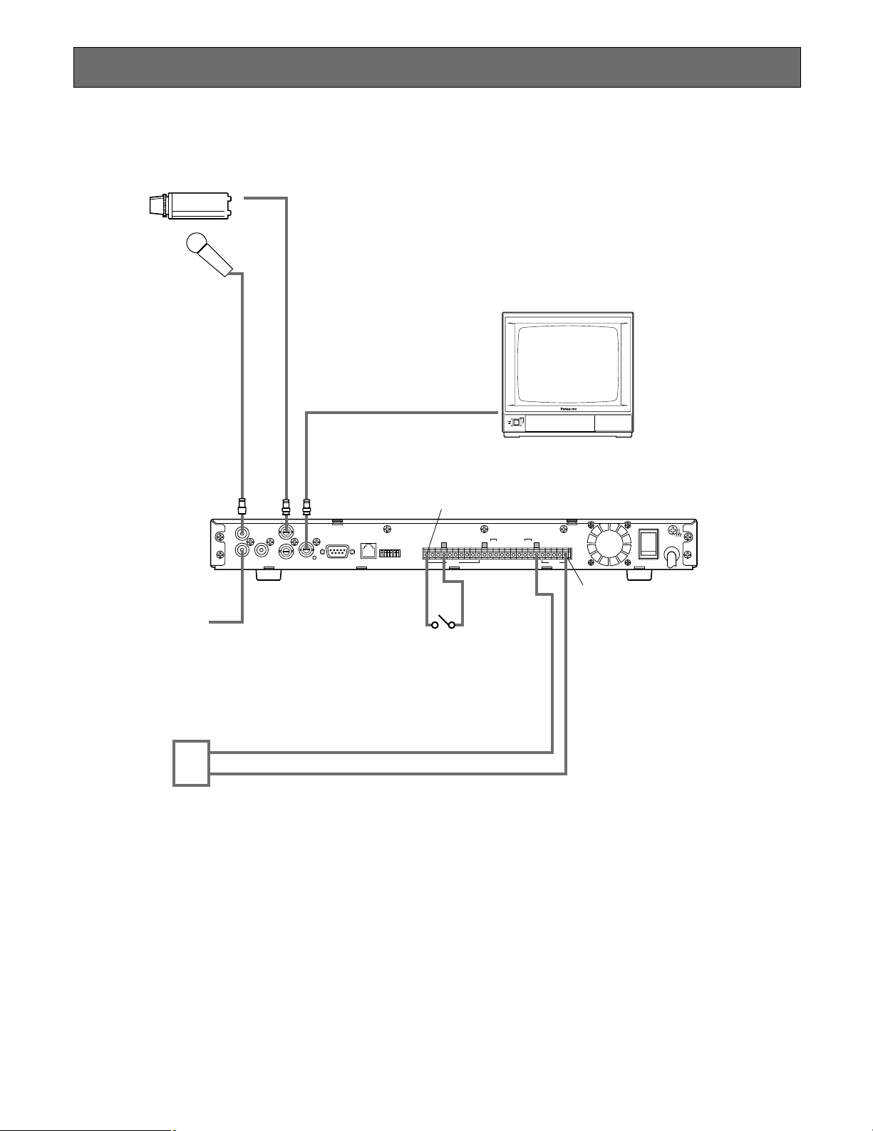
CONNECTION
SIGNAL GND
ALARM
SERIES
RECORD
TIME
ADJUST
REMOTE
MODEDATARS-232CVIDEO
OUT
IN
OUT
IN
AUDIO
MONITOR OUT
(PLAY)
CAMERA
SW OUT
G
G
G
JOG-CLICK
(EXT REC)
JOG-LEFT
JOG-RIGHT
ALARM SEARCH
STEP
REW/FF
STOP/SETUP
PLAY
REC
OUT
PLAY OUT
REC OUT
AUTO OFF OUT
DISK END OUTINOUTINRECALL
OUT
RECOVER OUT
RESET IN
IN
POWER
ON
OFF
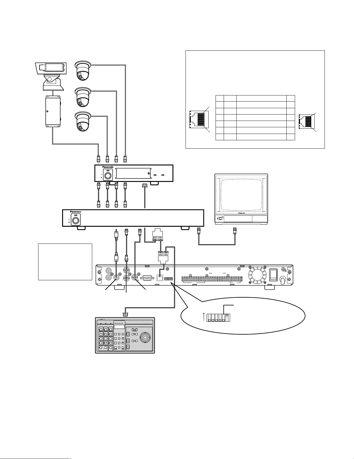
Jog Click (EXT REC)
EXT REC Mode Switch
To Speaker
Monitor Out
Video Monitor
Digital Disk Recorder WJ-HD100
Camera
Microphone
Sensor
Alarm In
Video
In
Audio In
IN
OFF
POWER
Video Input
■ Basic Connection
To select the recording mode from an external device connected to the EXT REC mode switch, the JOG/EXT REC parameter in
the REC SETUP menu must be set to EXT REC.
10
Page 11
■ Connections with PS•Data Equipment
SIGNAL GND
ALARM
SERIES
RECORD
TIME
ADJUST
REMOTE
MODEDATARS-232CVIDEO
OUT
IN
OUT
IN
AUDIO
MONITOR OUT
(PLAY)
CAMERA
SW OUT
G
G
G
JOG-CLICK
JOG-LEFT
JOG-RIGHT
ALARM SEARCH
STEP
REW/FF
STOP/SETUP
PLAY
REC
OUT
PLAY OUT
REC OUT
AUTO OFF OUT
DISK END OUTINOUTINRECALL
OUT
RECOVER OUT
RESET IN
IN
POWER
ON
OFF
ON
OFF
POWER
POWER
ON
OFF
ALARM
Data Multiplex Unit WJ-MP204
ALARM
SUSPEND
System Controller
POWER
ON
OFF
ON
Camera
DATA Port
DATA Port
Multi Screen
Out
Data Multiplex Unit
Video Multiplexer
Camera In
Camera Out
Video Monitor
Set the termination to
ON for the units at both
ends of the chain, and to
OFF for units in the
middle.
System Controller with PS•Data
Capability
DATA Port
Digital Disk Recorder WJ-HD100
Monitor Out
Video In
Video In
Rec
Out
Play
In
Video In
DATA Port
MODE
Camera SW
In
Camera SW
Out
(EXT REC)
Note:
Set the field rate to
6.2 fps or slower when
connecting the Camera
SW Out signal with the
video multiplexer.
1
6
1
6
No. No.
Name
Data Flow
11
GND
–
22
RX(B)
WJ-HD100
←
WV-CU360
33
RX(A)
WJ-HD100
←
WV-CU360
44
TX(B)
WJ-HD100
→
WV-CU360
55
TX(A)
WJ-HD100
→
WV-CU360
66
GND
–
Controller
end
If the cable is locally procured, make sure it is data
grade cable suitable for RS-485 communication. A 2wire twisted pair shielded cable, BELDEN 9406 or
equivalent should be used. Pin assignments and data
flow are shown below.
PS•Data equipment must be set up for communication as follows:
• Protocol selection: PS
• Unit Address: Set an address unique in the chain.
• Baud rate, data bit length, parity check, stop bit: Choose the same settings as used for the other equipment in the chain.
Recommended video multiplexers are Panasonic’s WJ-FS series or similar models having specifications as follows.
11
• Switching recognition signal is located within 8H prior to the end of vertical blanking.
• A camera switching rate of 4/50 seconds or more is available.
•
DATA
Page 12
ON
OFF
POWER
POWER
ON
OFF
SIGNAL GND
ALARM
SERIES
RECORD
TIME
ADJUST
REMOTE
MODEDATARS-232CVIDEO
OUT
IN
OUT
IN
AUDIO
MONITOR OUT
(PLAY)
CAMERA
SW OUT
G
G
G
ON
OFF
JOG-CLICK
JOG-LEFT
JOG-RIGHT
ALARM SEARCH
STEP
REW/FF
STOP/SETUP
PLAY
REC
OUT
PLAY OUT
REC OUT
AUTO OFF OUT
DISK END OUTINOUTINREC ALL
OUT
RECOVER OUT
RESET IN
IN
SIGNAL GND
ALARM
SERIES
RECORD
TIME
ADJUST
REMOTE
MODEDATARS-232CVIDEO
OUT
IN
OUT
IN
AUDIO
MONITOR OUT
(PLAY)
CAMERA
SW OUT
G
G
G
ON
OFF
JOG-CLICK
JOG-LEFT
JOG-RIGHT
ALARM SEARCH
STEP
REW/FF
STOP/SETUP
PLAY
REC
OUT
PLAY OUT
REC OUT
AUTO OFF OUT
DISK END OUTINOUTINREC ALL
OUT
RECOVER OUT
RESET IN
IN
Camera
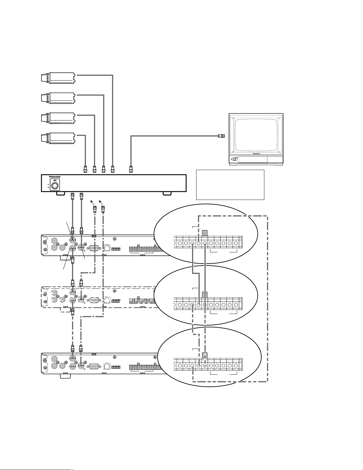
1st Recorder
Video Out
Video In
Video Monitor
Connect only when configuring
a loop recording.
Monitor
Out
ALARM
SERIES
RECORD
G
AUTO OFF OUT
DISK END OUT
OUTINRECALL
OUT
RECOVER OUT
RESET IN
IN
ALARM
SERIES
RECORD
G
AUTO OFF OUT
DISK END OUT
OUTINRECALL
OUT
RECOVER OUT
RESET IN
IN
ALARM
SERIES
RECORD
G
AUTO OFF OUT
DISK END OUT
OUTINRECALL
OUT
RECOVER OUT
RESET IN
IN
Recorder
(up to 16th)
2nd Recorder
Video Multiplexer
Monitor Out
Video In
Rec Out
Playback In
(EXT REC)
(EXT REC)
Note:
Set the field rate to 6.2 fps or
slower when connecting the
Camera SW Out signal with
the video multiplexer.
■ Series Connection
The diagram below shows an example where multiple disk recorders are connected in series or loop for long time recording,
and a video multiplexer is used.
12
Recommended video multiplexers are Panasonic’s WJ-FS series or similar models having specifications as follows.
• Switching recognition signal is located within 8H prior to the end of vertical blanking.
• A camera switching rate of 4/50 seconds or more is available.
See SERIES RECORDING in APPENDIX for setup and operating procedures.
Page 13
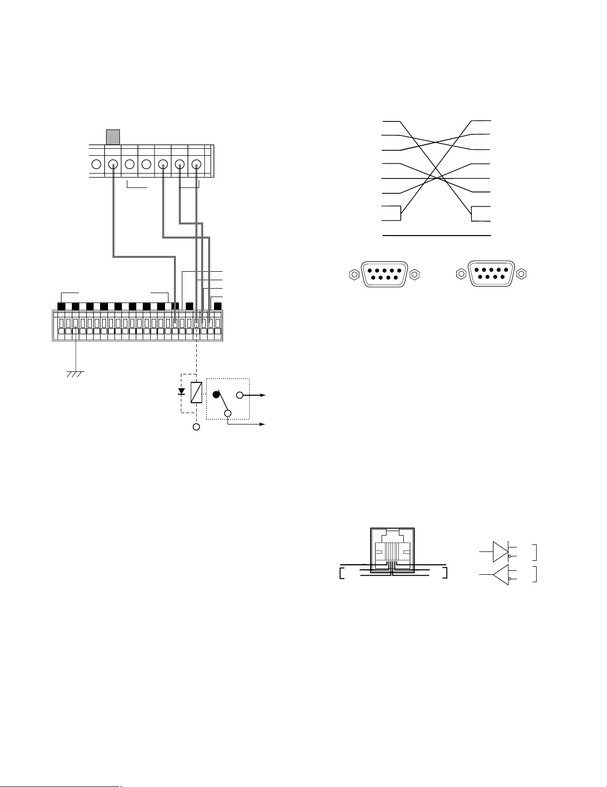
■ Alarm T erminal Connection
■ RS-232C Connection
A connection example is shown below.
Digital Disk Recorder
WJ-HD100
G
RECALL
OUT
RECOVER OUT
RESET IN
ALARM
External device
REMOTE/ALARM IN
87654321
GGGGGGGGGGG
IN
CONTROL IN
ALARM OUT
RECOVER OUT
RESET IN
Use an RS-232C cable (not included) as shown below to
connect the RS-232C terminal with a personal computer or
the like. The protocol selection in the COMMUNICATION
SETUP must be set to VTR.
1
2
3
4
5
6
7
8
Frame
9-pin D-sub connector
(female)
Shield
9-pin D-sub connector
1
2
3
4
5
6
7
8
Frame
(female)
NC: Normally Closed
Relay
+24V
NO: Normally Open
NO
NC
To Alarm
Indicator
IN: Stands for Alarm Signal In. Connect directly with a
sensor unit or indirectly with a unit having sensor
output capability to the recorder. The recorder
enters alarm recording mode when the alarm signal
(active when low) comes in.
RESET IN: Receives the reset signal (active when low)
from a connected device.
RECOVER OUT: Supplies the reset signal when the
RESET IN is received, the [■ STOP] button is
pressed, or the AUTO RESET time elapses.
OUT: Stands for the status output active until an alarm
is reset.
■ PS•Data Connection
Connect the DATA terminal on the rear panel to a system
component with a modular cable (not included) in the PS
Data chain. The protocol selection in the COMMUNICATION SETUP must be set to PS
dure for unit address setup (page 14, 30) and termination
(page 14).
Panasonic part # WV-CA48 series, RS-485 cables and connectors are recommended for the connection.
GND
RA
RX
RB
DATA
•
DATA. Follow the proce-
GND
TB
TX
TA
TA
TB
RA
RB
TX
RX
•
13
RECALL: The alarm history is displayed on the Monitor
every time the external switch is turned on.
GND: Signal ground
Page 14
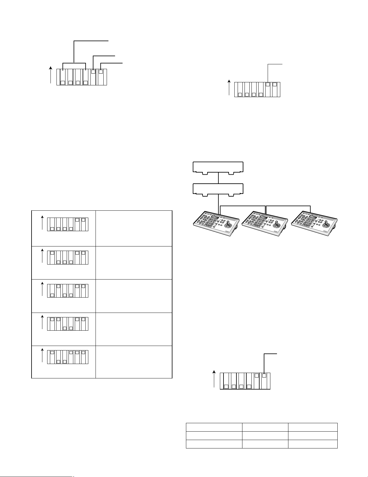
■ Mode Switch Setting
360
360
360
Unit Address/Initializing
Termination
ON
Alarm Out Polarity
● Termination
Set DIP switch #5 to ON or OFF position depending on the
type of connection and the unit's position within the daisy
chain.
Termination Switch
1234 56
MODE
The 6-bit DIP switch on the rear panel is used as follows.
#1 through #4: For setting the unit address or initializ-
ing the setup data
#5: Termination for communication lines
#6: For setting the polarity of the alarm output signal
● Unit Address & Initialize
The unit address can be set either on the setup menu or by
setting this DIP switch.
ON
1234 56
MODE
ON
1234 56
MODE
Unit address is specified in
the setup window.
Unit address 1
ON
1234 56
MODE
Daisy Chain Connection: Set the termination to ON for the
units at both ends of the RS-485 chain (PS
OFF for units in the middle.
System Component
Termination ON
Termination OFF
1
2
3
4
5
6
7
8
9
0
Termination
OFF
S
y
s
t
e
m
C
o
n
t
r
o
l
l
e
r
W
U
C
U
360
For PS.D
.LIN
K
1
2
3
4
5
6
7
8
9
0
Termination
OFF
S
y
s
t
e
m
C
o
n
t
r
o
l
l
e
r
W
U
C
U
360
F
or
P
S.D
.L
INK
Home run Connection: For a one-to-one connection, set
the termination to ON.
•
Data), and to
1
2
3
4
5
6
7
8
9
0
Termination
ON
S
y
s
t
e
m
C
o
n
t
r
o
ll
e
r
W
U
C
U
360
For P
S.D.LIN
K
ON
Unit address 2
1234 56
MODE
ON
1234 56
Unit address 3
MODE
ON
1234 56
All disk contents and setup
data are initialized.
MODE
Note: Do not use switch combinations other than shown above.
● Alarm Output Polarity
The DIP switch #6 specifies the polarity of ALARM OUT and
ALARM RECOVER output signals. Select [active-low] or
[active-high] depending on the type of the connected
device. See the manual included in the connected device
for acceptable signal polarity. The default setting is ON
[active-high].
Polarity switch
ON
1234 56
MODE
Switch #6 vs Polarity (when active)
ON (active-high) OFF (active-low)
ALARM OUT
ALARM RECOVER OUT
+12 V DC
+5 V DC
Open-collector low
Open-collector low
14
Page 15
SETUP PROCEDURES
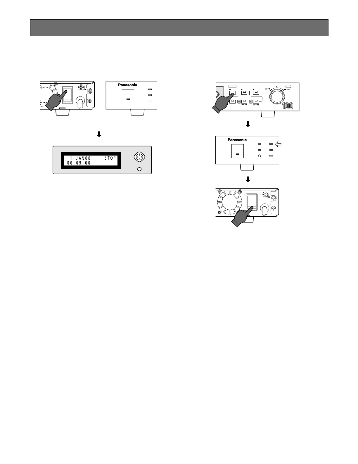
■ Prior to Setup
● Turning On the Power
POWER
ON
OFF
SIGNAL GND
OPERATE
DISPLAY SELECT
LCD CONTRAST
1. Plug the power cord into the AC outlet.
2. Turn on the power switch on the rear panel.
The operate LED lights, and the date, time and operating status are displayed on the LCD.
TIMER
ALARM
SUSPEND
SUMMER
TIME
● Turning Off the Power
DISPLAY SELECT
LCD CONTRAST
SETUP/ESC
STOP
PLAY REC
PLAY MODE SELECT
ALARM SEARCH STEP REW/FF
//
Digital Disk Recorder WJ-HD
TIMER HDD
ALARM
OPERATE
SUSPEND
SUMMER
POWER
ON
OFF
/
TIME
SIGNAL GND
PUSH– PAUSE
FULL
LOCK
SET
/
Confirm that
the HDD access
indicator is off.
Power-on recording will start if [Timer Rec] has been set to
[EXT] with the LCD button.
Note: Avoid turning the power on and off within a short
time. Allow at least 5 seconds from off to on and
vice versa.
1. Press the stop button to quit recording or playback.
Make certain that the HDD access lamp turns off.
2. Turn off the power switch on the rear panel.
The operate LED goes out, and the operating status on
the LCD disappears.
Note:
• Do not turn off the power while the HDD access
lamp is on.
• Do not leave the unit turned off for a long time.
Supply AC power to the unit and turn it on to charge
up the backup battery.
15
Page 16

● Displaying the SETUP MENU
WJ-HD100 SETUP MENU
CLOCK
→
1.JAN00 0:00
TIME&DATE TYPE1 24H
TIME&DATE DISP.ON
TIME&DATE POSI.R-LOWER
STATUS DISP. ON
STATUS POSI. R-LOWER
HDD FULL 1%
SETUP MENU
STOP PLAY REC
PUSH– PAUSE
SET
ALARM SEARCH STEP REW/FF
PLAY MODE SELECT
//
/
/
SETUP/ESC
Digital Disk Recorder WJ-HD
1. Confirm that the camera and peripherals are connected correctly and securely.
2. Turn on the power switches of all system components.
3. Hold down the SETUP/ESC button for 2 seconds or more. The WJ-HD100 SETUP MENU appears on the monitor.
Clock Setup
Time & Date
Display Setup
Status
Display Setup
● Buttons and Dials Used for the Setup
[▲] button: Moves the cursor upward in a menu, and opens the previous menu page.
[▼] button: Moves the cursor downward in a menu page, and opens the next page menu.
JogDial (Clockwise):
JogDial (Counter-clockwise):
JogDial (Pressing):
[SETUP/ESC] [■ STOP] button (pressing):
[SETUP/ESC] [■ STOP] button (holding down):
16
Increases the parameter value.
Decreases the parameter value.
Validates the selected parameter, and moves the cursor to the right.
Moves the cursor to the left.
Opens the setup window or escapes from it and switches back to normal operation.
Page 17

● Setup Menu Sequence
WJ-HD100 SETUP MENU
CLOCK
→
1.JAN00 0:00
TIME&DATE TYPE1 24H
TIME&DATE DISP.ON
TIME&DATE POSI.R-LOWER
STATUS DISP. ON
STATUS POSI. R-LOWER
HDD FULL 1%
REC SETUP
REC MODE SF- 12H
REC RATE 12.5FPS
REC QUALITY 10(1-10)
DISK END MODE STOP
DISK END BUZZER ON
JOG/EXT REC JOG CLICK
REC MODE SF- 12H
ALARM SETUP
REC MODE SF- 12H
REC RATE 12.5FPS
REC QUALITY 10(1-10)
DURATION 10S
ALARM BUZZER ON
VMD SETUP OFF
INTERNAL TIMER REC
TIMER START END T-M
S ON→ 8:00 8:20 SF-A 12
M OFF
T ON
→
12:00 8:00 SF- 12
W OFF
T ON
→
14:00 23:00 SF- 240
F OFF
S ON
→
12:00 18:00 FQ-A 24
D ON
→
18:00 18:50 NQ-A 24
COMMUNICATION SETUP
PROTOCOL PS•DATA
UNIT ADDRESS 1
BAUD RATE 9600
DATA BIT 8
PARITY CHECK NONE
STOP BIT 1
WAIT TIME OFF
SYSTEM INFORMATION
HDD HOUR METER 1000H
HDD CAPACITY . GB
DEFAULT
→
SET
→
VERSION X.XX X.XX X.XX
SYSTEM SETUP
FWD/REW MODE SKIP&PLAY
PASSWORD LOCK OFF
ALL
→
*****
OPERATION
→
*****
KEYLOCK BUZZER OFF
RESET PULSE HIGH
TIME ADJUSTING SLAVE
SET TIME
→
9:00
AUTO ERASING OFF
The WJ-HD100 provides the following seven setup menus: WJ-HD100 SETUP MENU, SYSTEM SETUP, REC SETUP, ALARM
SETUP, INTERNAL TIMER REC, COMMUNICATION SETUP and SYSTEM INFORMATION. Pressing the [▲] or [▼] button
repeatedly will switch the menu as follows.
Note: HDD CAPACITY indicates the total usable capacity
of the built-in hard disk.
The item or parameter selected and highlighted on the monitor menu is also displayed on the LCD.
17
Page 18

■ Initializing
You can either initialize all disk contents including image
data and setup data, or setup data only.
● Initializing All Contents & Setup Data
Warning! The following are irrevocable procedures.
We strongly recommend that you copy important pictures from the hard disk to CompactFlash cards
before initializing.
● Initializing Setup Data
SYSTEM INFORMATION
HDD HOUR METER 1000H
HDD CAPACITY . GB
DEFAULT
→
SET
→
ON
OFF
ON
123456
MODE
1. Press the [■ STOP] button to stop recording or playback.
2. Turn off the power.
3. Set MODE switches #1 through 4 on the rear panel as
follows:
#1: ON
#2: OFF
#3: OFF
#4: ON
4. Turn on the power.
The disk contents and setup data are initialized.
1. Open the SYSTEM INFORMATION window, then move
the cursor to DEFAULT.
2. Press the JogDial to move the cursor to SET.
3. Press the JogDial.
4. Select YES with the JogDial.
YES: Initializing of setup data is enabled.
5. Press the JogDial.
SET DONE appears on the monitor after initializing.
6. Press the [SETUP/ESC] button.
The cursor moves to DEFAULT.
7. Hold down the [SETUP/ESC] button for 2 seconds to
quit the setup.
NOW FORMATTING HDD
5. Turn off the power, and return the MODE switches to
the previous positions.
18
Page 19

■ WJ-HD100 SETUP MENU
● Clock Setup
001 CLOCK>
Set the internal timer to the present time and date.
The default value is “1.JAN00 0:00”.
1. Hold down the [SETUP/ESC] button for 2 seconds to
display the setup menu on the monitor.
2. Move the cursor on the monitor to CLOCK with the [▲]
or [▼] button. The selected item appears also on the
LCD with item number (001 in this case), and parameters (1.JAN00 0:00, day-month-year and time) in the
second line.
WJ-HD100 SETUP MENU
CLOCK
→
00 0:00
1.JAN
TIME&DATE TYPE1 24H
TIME&DATE DISP.ON
TIME&DATE POSI.R-LOWER
STATUS DISP. ON
STATUS POSI. R-LOWER
HDD FULL 99%
● Time & Date Type
002 TIME&DATE TYPE
DISPLAY SELECT
LCD CONTRAST
DISPLAY SELECT
LCD CONTRAST
1, 6, 7
SETUP/ESC
PLAY REC
STOP
PLAY MODE SELECT
ALARM SEARCH STEP REW/FF
//
Digital Disk Recorder WJ-HD
3, 4
PUSH– PAUSE
/
SET
/
2
WJ-HD100 SETUP MENU
CLOCK
→
1.JAN00 0:00
TIME&DATE TYPE1 24H
TIME&DATE DISP.ON
TIME&DATE POSI.R-LOWER
STATUS DISP. ON
STATUS POSI. R-LOWER
HDD FULL 1%
DISPLAY SELECT
LCD CONTRAST
3. Move the cursor to the right by pressing the JogDial.
The cursor highlights the item position (day digits).
Select the 24-hour or AM-PM time system. When AM-PM is
selected, the time is followed by A or P, for example, 7:00
A.
You can also select display style TYPE1 or TYPE2 as shown
below.
1.JAN00 7:07:00
TYPE1
1.JAN00
7:07:00
TYPE2
WJ-HD100 SETUP MENU
CLOCK
→
1.JAN00 7:07
TIME&DATE TYPE1 24H
TIME&DATE DISP.ON
TIME&DATE POSI.R-LOWER
STATUS DISP. ON
STATUS POSI. R-LOWER
DISPLAY SELECT
HDD FULL 99%
LCD CONTRAST
4. Select the appropriate parameter (day) by rotating the
JogDial.
5. Repeat the above steps 3 and 4 to set month, year and
time.
6. Press the [SETUP/ESC] button.
7. Hold down the [SETUP/ESC] button for 2 seconds to
quit the setup.
Note: Beside the JogDial the [▲] and [▼] buttons are also
used to move the cursor for setting time and date.
19
1. Move the cursor to TIME&DATE with the [▲] or [▼] button.
2. Select the parameter with the JogDial. The default value
is TYPE1 24H.
TYPE1 24H: Time & date are displayed in one line in
the 24-hour system.
TYPE1 12H: Time & date are displayed in one line in
the AM-PM system.
TYPE2 24H: Time & date are displayed in two lines in
the 24-hour system.
TYPE2 12H: Time & date are displayed in two lines in
the AM-PM system.
Page 20

● Time & Date Display
PLAY PLAY
PLAY PLAY
L-UPPER
L-LOWER
R-UPPER
R-LOWER
CENTRE
PLAY
7.JAN00 7:07:00 7.JAN00 7:07:00
7.JAN00 7:07:00 7.JAN00 7:07:00
L-UPPER
L-LOWER
R-UPPER
CENTRE
R-LOWER
7.JAN00 7:07:00
003 T&D DISPLAY
Select ON or OFF to show or hide the time and date display
on the monitor. The LCD is not affected by this selection.
CLOCK→ 7.JAN00 8:09
TIME&DATE TYPE1 24H
TIME&DATE DISP.ON
TIME&DATE POSI.R-LOWER
STATUS DISP. ON
STATUS POSI. R-LOWER
HDD FULL 1%
2. Select the desired position with the JogDial. The default
is R-LOWER.
L-UPPER: Displays time & date in the left upper corner.
R-UPPER: Displays time & date in the right upper cor-
ner.
CENTRE: Displays time & date in the centre.
L-LOWER: Displays time & date in the left lower corner.
R-LOWER: Displays time & date in the right lower cor-
ner.
OFF: Time & date display is disabled.
DISPLAY SELECT
LCD CONTRAST
1. Move the cursor to TIME&DATE DISP. with the [▲] or
[▼] button.
2. Select either ON or OFF with the JogDial. The default is
ON.
ON: Shows time and date on the monitor.
OFF: Hides time and date.
● Time & Date Position
004 T&D POSITION
Select one of six available positions (including OFF) for
having the time & date displayed on the monitor. The LCD
is not affected by this selection.
● Status Display
005 STATUS DISP.
Select ON or OFF to show or hide the status display on the
monitor. The LCD is not affected by this selection.
CLOCK→ 7.JAN00 8:09
TIME&DATE TYPE1 24H
TIME&DATE DISP.ON
TIME&DATE POSI.R-LOWER
STATUS DISP. ON
STATUS POSI. R-LOWER
HDD FULL 1%
DISPLAY SELECT
LCD CONTRAST
1. Move the cursor to STATUS DISP. with the [▲] or [▼]
button.
2. Select either ON or OFF with the JogDial. The default is
ON.
ON: Shows the operating status on the monitor.
OFF: Hides the status.
CLOCK→ 7.JAN00 8:09
TIME&DATE TYPE1 24H
TIME&DATE DISP.ON
TIME&DATE POSI.R-LOWER
STATUS DISP. ON
STATUS POSI. R-LOWER
HDD FULL 1%
1. Move the cursor to TIME&DATE POSI. with the [▲] or
[▼] button.
20
DISPLAY SELECT
LCD CONTRAST
● Status Position
006 STATUS POSI.
Select one of six available positions (including OFF) for
having the status displayed on the monitor. The LCD is not
affected by this selection. The status display appears right
under the time & date display if the same position is selected for both.
Page 21

CLOCK→ 7.JAN00 8:09
TIME&DATE TYPE1 24H
TIME&DATE DISP.ON
TIME&DATE POSI.R-LOWER
STATUS DISP. ON
STATUS POSI. R-LOWER
HDD FULL 1%
DISPLAY SELECT
■ SYSTEM SETUP
● Quick Play Mode Selection
101 FWD/REW MODE
Picture search is available in quick forward and backward
playback. Set the playback picture rate (FWD/REW MODE)
in the SYSTEM SETUP window to SKIP or SKIP&PLAY. The
playback sequence for each mode is shown below.
LCD CONTRAST
1. Move the cursor to STATUS POSI. with the [▲] or [▼]
button.
2. Select the desired position with the JogDial. The default
is R-LOWER.
L-UPPER: Displays the status in the left upper corner.
R-UPPER: Displays it in the right upper corner.
CENTRE: Displays it in the centre.
L-LOWER: Displays it in the left lower corner.
R-LOWER: Displays it in the right lower corner.
OFF: Status display is disabled.
● HDD FULL Selection
007 HDD FULL
Set the disk capacity from 1 % to 99 % to warn the operator
that the available capacity is nearing the end. There are two
warning levels. First the FULL indicator on the front panel
blinks when the remaining disk capacity has reached the
preset value. Finally the buzzer beeps when the disk is full,
provided that the DISK END BUZZER parameter in the REC
SETUP menu is set to ON. At the same time the FULL indicator turns on.
CLOCK→ 7.JAN00 8:09
TIME&DATE TYPE1 24H
TIME&DATE DISP.ON
TIME&DATE POSI.R-LOWER
STATUS DISP. ON
STATUS POSI. R-LOWER
HDD FULL 1%
DISPLAY SELECT
LCD CONTRAST
SKIP
Data recorded
on the Disk
Image displayed
on the Monitor
SKIP&PLAY
Data recorded
on the Disk
Image displayed
on the Monitor
1. Hold down the [SETUP/ESC] button for 2 seconds to
display the setup menu on the monitor.
2. Press the down [▼] button repeatedly until the SYSTEM
SETUP window appears. (You can switch through the
setup menus by repeatedly pressing the up [▲] or
down [▼] button.)
3. Move the cursor to FWD/REW MODE with the up [▲] or
down [▼] button.
4. Rotate the JogDial to select the desired parameter. The
default is SKIP&PLAY.
[SKIP]: One field still picture is picked up from the disk
and displayed on the monitor as shown above. This
is quicker than skip and play.
[SKIP&PLAY]: A 32-field series of pictures is played
back. We recommend that you select [SKIP&PLAY]
when a video multiplexer is installed in the system.
Skip
1 Field Still Image
Skip Play
A Series of 32 Fields
Time
Expanded
Time
Time
Expanded
Time
SYSTEM SETUP
FWD/REW MODE SKIP&PLAY
PASSWORD LOCK OFF
→
ALL
OPERATION
*****
→
*****
KEYLOCK BUZZER OFF
RESET PULSE HIGH
TIME ADJUSTING SLAVE
→
SET TIME
9:00
AUTO ERASING OFF
1. Move the cursor to HDD FULL with the [▲] or [▼] button.
2. Select the desired value with the JogDial. The default
value is 1 %.
1% to 99 %: The FULL indicator blinks when the
remaining disk capacity reaches the selected value.
21
DISPLAY SELECT
LCD CONTRAST
5. Press the [SETUP/ESC] button for 2 seconds to quit
setup.
Page 22

● Password Setup
OPERATE
TIMER HDD
ALARM
SUSPEND
SUMMER
TIME
FULL
LOCK
MEMORY CARD
DISP
LCD
DISPLAY SELECT
LCD CONTRAST
SYSTEM SETUP
FWD/REW MODE SKIP&PLAY
PASSWORD LOCK OFF
ALL
→
*****
OPERATION
→
*****
KEYLOCK BUZZER OFF
RESET PULSE HIGH
TIME ADJUSTING SLAVE
SET TIME
→
9:00
AUTO ERASING OFF
DISPLAY SELECT
LCD CONTRAST
102 PASSWORD LOCK
A 5-digit password is entered to protect all settings, recorded pictures, and operating status, or settings only from
unauthorized access. While the LOCK indicator on the front
panel is on, the LCD displays the message "Now Key
Locked!" to warn unauthorized operators. If accessed in
this condition, the buzzer beeps.
Note: Select OFF when you do not need the button lock
mode. When set to ON, the recorder enters the button lock mode if neither a button nor the JogDial is
operated within a period of five minutes.
3. Move the cursor to ALL or OPERATION with the up [▲]
or down [▼] button.
ALL: Both normal operations and setup operations are
allowed.
OPERATION: Normal operations only are allowed.
4. Press the JogDial.
The preset password appears. The default is “12345”
for both ALL and OPERATION.
Turned on while the buttons are locked.
5. Select a number with the JogDial, then press it.
The cursor moves one digit to the right.
6. Repeat step 5 above until all digits are entered.
7. Press the [SETUP/ESC] button to confirm the entered
password. Go back to step 3 if you have not yet set the
OPERATION password.
● Setting Buzzer ON/OFF
105 KEYLOCK BUZ
SYSTEM SETUP
FWD/REW MODE SKIP&PLAY
PASSWORD LOCK OFF
ALL
OPERATION
KEYLOCK BUZZER OFF
RESET PULSE HIGH
TIME ADJUSTING SLAVE
SET TIME
AUTO ERASING OFF
→
*****
→
*****
→
9:00
1. Move the cursor to PASSWORD LOCK with the up [▲]
or down [▼] button.
2. Select either ON or OFF with the JogDial.
The default is OFF.
ON: Buttons are password protected against erroneous
operation and tampering. When set to ON, the
22
recorder enters the button lock mode if neither a
button nor the JogDial is operated within a period of
five minutes.
OFF: No password protection is applied unless the but-
ton lock mode is enabled using the LCD button as
described in the right column of this page.
DISPLAY SELECT
DISPLAY SELECT
LCD CONTRAST
LCD CONTRAST
1. Move the cursor to KEYLOCK BUZZER with the up [▲]
or down [▼] button.
2. Rotate the JogDial to select ON or OFF. The default is
OFF.
ON: Buzzer beeps when unauthorized access takes
place.
OFF: Buzzer does not sound.
Page 23

● Reset Pulse Polarity
106 RESET PULSE
● Set Time
108 SET TIME
The polarity of the alarm reset pulse is selected in the
SYSTEM SETUP window.
The reset pulse is supplied from an external device with
high or low active signal form to the RESET IN terminal
on the rear panel.
SYSTEM SETUP
FWD/REW MODE SKIP&PLAY
PASSWORD LOCK OFF
→
ALL
OPERATION
*****
→
*****
KEYLOCK BUZZER OFF
RESET PULSE HIGH
TIME ADJUSTING SLAVE
→
SET TIME
9:00
AUTO ERASING OFF
1. Open the system setup window, then move the cursor
to RESET PULSE with the up [▲] or down [▼] button.
2. Select either HIGH or LOW with the JogDial. The default
is HIGH.
HIGH: Stands for high-active. The recorder stops alarm
recording when a positive pulse is supplied.
LOW: Stands for low-active.
This setting specifies the hour for the master unit to supply
the Time Adjust OUT signal to the slave units once a day.
You need not set the hour when SLAVE is selected. The
slave unit accepts the signal through the IN terminal, and
corrects its internal clock to the hour as far as the clock
deviates within 15 minutes after or before the hour.
1. Move the cursor to SET TIME with the [▲] or [▼] button.
2. Select the desired time (00:00 to 23:00) with the
JogDial.
3. Press the JogDial.
● Auto Erasing
109 AUTO ERASING
The redundant records on the disk can be erased every
day at 24:00 mid night. Day numbers specified by this setting means that the records stored during the number of
days from the present will be protected, while the older
records than that of the protected day will be erased.
SYSTEM SETUP
● Time Adjusting
107 TIME ADJUSTING
IN and OUT terminals for a calibration signal are provided
on the TIME ADJUST terminal board on the rear panel. The
master unit supplies the calibration signal to the slaves.
This is convenient for synchronizing the internal clock with
other connected devices. Make certain to connect the IN
and OUT terminals correctly.
SYSTEM SETUP
FWD/REW MODE SKIP&PLAY
PASSWORD LOCK OFF
ALL
OPERATION
KEYLOCK BUZZER OFF
RESET PULSE HIGH
TIME ADJUSTING SLAVE
SET TIME
AUTO ERASING OFF
1. Move the cursor to TIME ADJUSTING with the [▲] or
[▼] button.
2. Select either MASTER or SLAVE with the JogDial. The
default is SLAVE.
MASTER: The unit supplies the calibration OUT signal
to the slave units.
SLAVE: The internal timer of the unit is supplied the cali-
bration signal from the master.
→
*****
→
*****
→
9:00
FWD/REW MODE SKIP&PLAY
PASSWORD LOCK OFF
→
ALL
OPERATION
*****
→
*****
KEYLOCK BUZZER OFF
RESET PULSE HIGH
TIME ADJUSTING SLAVE
→
SET TIME
9:00
AUTO ERASING OFF
1. Move the cursor to AUTO ERASING with the [▲] or [▼]
button.
2. Select the desired day number with the JogDial.
OFF: Auto erasing is not applied.
1DAY: Only today’s records of 0:00 onward are protect-
ed. Records before 24:00 of yesterday are erased.
2 to 10DAYS: Records before the specified number of
days are erased.
14, 30, 45, 60, 90, 120, 150, 180DAYS: Same as
above.
Notes:
• The day number includes today as 1 day, therefore
2DAYS counts today and yesterday in number.
• Auto Erasing is implemented at 24:00 mid night.
Playing back will stop once when the time comes to
24:00, then will restart with different portion based
on the renewed day count.
23
Page 24

■ REC SETUP
Picture quality and field rate are selected as a set or individually.
● Recording Mode
201 REC MODE
Select one of the following 5 basic options: super fine (SF,
level 10), fine (FQ, level 8), normal (NQ, level 7), long-time
recording (EX, level 5) and optional (SP). If combined with
audio (A) recording, the number or modes doubles as
shown below. The selected recording mode determines the
remaining recording time which is displayed on the monitor
and on the LCD.
In the SP mode, the field rate and picture quality are variable and can be selected at option in the range of 0.1 to
12.5 fps and level 1 to 10, respectively. After the recording
mode has been selected, the available time is calculated
and displayed. "xxx" in the table is replaced with the calculated available time.
● Recording Field Rate
202 REC RATE
The field rate or number of fields per second can be selected in SP mode. The higher the field rate, the more information the recording will contain.
REC MODE SP- 12H
REC RATE 12.5FPS
REC QUALITY 10(1-10)
DISPLAY SELECT
LCD CONTRAST
1. Move the cursor to REC RATE with the [▲] or [▼] button.
2. Select the desired rate (from 0.1FPS to 12.5FPS) with
the JogDial. The default value is 12.5 fps.
REC SETUP
REC MODE SF- 12H
REC RATE 12.5FPS
REC QUALITY 10(1-10)
DISK END MODE STOP
DISK END BUZZER ON
JOG/EXT REC JOG CLICK
REC MODE SF- 12H
DISPLAY SELECT
LCD CONTRAST
1. Move the cursor to REC MODE with the [▲] or [▼] button.
2. Select the desired mode with the JogDial.
The default is SF-12H.
Rec Mode Quality Audio Record Note
SF-xxxH Super Fine (10) N/A
FQ-xxxH
NQ-xxxH
EX-xxxH
SF-AxxxH
FQ-AxxxH
NQ-AxxxH
EX-AxxxH
SP-xxxH
Fine (8)
Normal (7)
Long time (5)
Super Fine (10)
Fine (8)
Normal (7)
Long time (5)
Optional setup
N/A
N/A
N/A
Available
Available
Available
Available
AvailableOptional setupSP-AxxxH
N/A
Field rate, quality
selected optionally
Field rate, quality
selected optionally
● Recording Quality
203 REC QUALITY
A picture quality from level 1 to 10 can be selected in SP
mode. The higher the level number, the better the picture
quality will be.
REC MODE SP- 12H
REC RATE 12.5FPS
REC QUALITY 10(1-10)
DISPLAY SELECT
LCD CONTRAST
1. Move the cursor to REC QUALITY with the [▲] or [▼]
button.
2. Select the desired quality (from level 1 to 10) with the
JogDial. The default value is level 10.
"xxx" in the table will be replaced by a calculated recording
time of 6, 12, 18, 24, 48, 72, 96, 120, 170, 180, 240, 480 or
960 hours. “xxx” for SP is specified in REC MODE table in
ADDENDUM attached to the manual.
24
Page 25

● Disk End Mode Setup
204 DISK END
The menu offers the following four options at the point where the available recording space on the disk is used up: [STOP],
[CONTINUE], [ALM CONTINUE] and [SERIES]. See illustration for each sequence.
DISK ENDDISK START
[STOP]
[Default]
[CONTINUE]
Restart
REC
Reset [STOP]
Overwritten automatically
Stop
REC
The default is [STOP].
DISK ENDDISK START
DISK ENDDISK START
DISK ENDDISK START
[ALM CONTINUE]
[SERIES]
REC only ALM
picture
Disk #1
Disk #n (up to #16)
Alarm
DISK ENDDISK START
Stop
REC
DISK ENDDISK START
Recording continues from the
start of the next recorder's disk
Disk #2
DISK ENDDISK START
Disk #3
DISK STARTDISK END
DISK ENDDISK START
DISK STARTDISK END
Notes on SERIES connection
• See page 12 for physical connections.
• See SERIES RECORDING in APPENDIX for setup and operating procedures.
25
Loop recording
if connected in
loop
Page 26

DISPLAY SELECT
JOG/EXT REC EXT REC
EXT REC MODE SF- 12H
REC SETUP
REC MODE SF- 12H
REC RATE 12.5FPS
REC QUALITY 10(1-10)
DISK END MODE STOP
DISK END BUZZER ON
JOG/EXT REC JOG CLICK
REC MODE SF- 12H
LCD CONTRAST
1. Move the cursor to DISK END MODE with the up [▲] or
down [▼] button.
2. Rotate the JogDial to select the desired parameter. The
default is STOP.
[STOP]: Stops recording until a mode other than
[STOP] is selected.
[CONTINUE]: Old data is automatically overwritten from
the disk start.
[ALM CONTINUE]: Recording is suspended until an
alarm occurs. When an alarm occurs, alarm recording overwrites old data from the disk start.
[SERIES]: In series connection, new data is recorded
from start to end of the next recorder's disk and so
forth. In loop connection, new data continuously
overwrites old data.
[ON]: Enables the buzzer beep at the disk end (remain-
ing space 0 %).
[OFF]: Disables the buzzer beep.
● Jog Click Terminal Definition
206 JOG/EXT REC
The JOG CLICK terminal on the rear panel is connected
with an external switch. The switch is used either to remotely click the JogDial or to implement the preset mode for
manual recording.
JOG/EXT REC JOG CLICK
EXT REC MODE SF- 12H
DISPLAY SELECT
LCD CONTRAST
1. Move the cursor to the desired item with the [▲] or [▼]
button.
2. Select the appropriate parameter by rotating the
JogDial.
JOG CLICK: Turning on the external switch has the
same effect as pressing the JogDial.
EXT REC: While the switch is turned on, the preset EXT
REC mode is implemented.
● Disk End Buzzer Setup
205 DISK END BUZZER
The buzzer can be set up to beep at the point where the
disk is full (remaining space 0 %).
REC SETUP
REC MODE SF- 12H
REC RATE 12.5FPS
REC QUALITY 10(1-10)
DISK END MODE STOP
DISK END BUZZER ON
JOG/ EXT REC JOG CLICK
REC MODE SF- 12H
1. Move the cursor to DISK END BUZZER with the up [▲]
or down [▼] button.
2. Rotate the JogDial to select the desired parameter. The
default is ON.
● External Recording Mode
207 EXT REC MODE
Select the mode for manual recording after having set the
JOG/EXT parameter to EXT REC.
DISPLAY SELECT
LCD CONTRAST
1. Move the cursor to EXT REC MODE with the [▲] or [▼]
button.
2. Select the desired mode with the JogDial. Refer to page
24 for the recording mode parameters. The default
value is SF-12H.
26
Page 27

■ ALARM SETUP
The digital disk recorder accepts an alarm signal supplied
from connected device such as a camera or camera site
equipment. The recorder also generates an alarm signal
itself when the preset motion detection activates.
Any alarm signal starts alarm recording with the preset
recording mode, field rate and picture quality. Alarm
recording stops when the preset time has elapsed, the [■
STOP] [SETUP/ESC] button on the front panel is pressed,
or the alarm RESET IN is supplied from the connected
device. The recorder outputs an alarm recovery signal from
the rear panel.
● Alarm Recording Mode
301 REC MODE
ALARM SETUP
REC MODE SF- 12H
REC RATE 12.5FPS
REC QUALITY 10(1-10)
DURATION 10S
ALARM BUZZER ON
VMD SETUP OFF
This item specifies the recording mode to be applied exclusively to the sequence after an alarm input. The setting procedure and parameters are the same as for REC SETUP
described earlier.
REC MODE SF- 12H
REC RATE 12.5FPS
REC QUALITY 10(1-10)
DISPLAY SELECT
LCD CONTRAST
DURATION 10S
ALARM BUZZER ON
VMD SETUP OFF
DISPLAY SELECT
LCD CONTRAST
1. Move the cursor to DURATION with the [▲] or [▼] button.
2. Select the desired duration with the JogDial.
The default value is 10 seconds.
The unit will revert to the previous status when the time
has elapsed.
10S: 10 seconds
20S: 20 seconds
30S: 30 seconds
1M: 1 minute
2M: 2 minutes
3M: 3 minutes
6M: 6 minutes
MANUAL: Recording continues for as long as there is
alarm input or for at least 10 seconds, even if the
alarm input turns off earlier.
CONTINUE: Recording continues until the stop button
on the front panel is pressed, or the RESET IN signal is supplied.
OFF: Neither recording nor alarm logging is implement-
ed.
● Alarm Buzzer
305 ALARM BUZZER
ALARM SETUP
REC MODE SF- 12H
REC RATE 12.5FPS
REC QUALITY 10(1-10)
DURATION 10S
ALARM BUZZER ON
VMD SETUP OFF
● Alarm Recording Duration
304 DURATION
This setting specifies the duration of alarm recording and
related functions after an alarm input. Functions active during alarm recording are buzzer beeping, ALARM LED indication, "ALARM" status display, and the ALARM OUT signal.
27
DISPLAY SELECT
LCD CONTRAST
1. Move the cursor to ALARM BUZZER with the up [▲] or
down [▼] button.
Page 28

2. Rotate the JogDial to select ON or OFF.
ON: Buzzer beeps while alarm is active.
OFF: Buzzer does not beep.
● Motion Detector Setup
306 VMD SETUP
A VMD or Video Motion Detector senses changes in the
video signals within a preset area and supplies alarm output. When a change is detected, the recorder starts recording. The detection sensitivity and area are selected on this
menu.
ALARM SETUP
REC MODE SF- 12H
REC RATE 12.5FPS
REC QUALITY 10(1-10)
DURATION 10S
ALARM BUZZER ON
VMD SETUP OFF
Notes:
• VMD should be used with an ordinary camera input to
the unit. Select [OFF] to avoid useless VMD when a
video multiplexer or combination camera supplies the
input to the unit.
• Make sure that the date and status displays are not
located within the motion detection area on the monitor.
Otherwise the motion detector could be misled.
• Set the ALARM SUSPEND to ON with the LCD button
when VMD is unnecessarily activated during the VMD
setup.
• VMD does not function while playing back.
3. Set the upper-left end of the detection area. Move the
asterisk to the right or left with the JogDial, and up or
down by pressing the up [▲] or down [▼] button.
REW/FF
/
STEP
/
PUSH • PAUSE
/
SET
/
1. Move the cursor to VMD SETUP with the up [▲] or
down [▼] button.
2. Rotate the JogDial to select the desired parameter, then
press the JogDial. The default is OFF.
[LOW ]: Low sensitivity motion detection is enabled.
[MID ]: Medium sensitivity motion detection is
enabled.
[HIGH ]: High sensitivity motion detection is enabled.
[OFF]: Motion detection is disabled.
The area setup window appears with an asterisk when
other than OFF is selected. The asterisk represents the
upper-left or bottom-right of the detection area. The
division lines are not actually displayed on the monitor.
4. Press the JogDial to enter the upper-left end of the
detection area. The asterisk position is highlighted.
5. Set the bottom-right end of the detection area similar to
steps 3 and 4 above.
6. Press the JogDial. The area is highlighted.
Up to 4 areas can be selected. These may partially
overlap. Repeat steps 3 to 6 to select more areas. To
unselect an area, move the cursor to the upper-left end
of the area, and then press the JogDial.
q
e
w
r
28
Page 29

■ INTERNAL TIMER REC
P
D
Reservations for recording are made in the INTERNAL
TIMER REC window on a weekly or daily basis. The TIMER
indicator lights on the front panel after a reservation has
been made.
● Making Reservations
1. Move the cursor to the desired day line with the [▲] or
[▼] button.
Move the cursor to the D (bottom) line when a daily
basis reservation is made.
OPERATE
TIMER HDD
ALARM
SUSPEND
SUMMER
TIME
FULL
LOCK
MEMORY CARD
INTERNAL TIMER REC
TIMER START END T-M
S ON
→
8:00 8:20 SF-A 12
M OFF
→
T ON
12:00 8:00 SF- 12
W OFF
→
T ON
14:00 23:00 SF- 240
F OFF
→
S ON
D ON
The column titles in the window denote the following:
12:00 18:00 FQ-A 24
→
18:00 18:50 NQ-A 24
DISPLAY SELECT
LCD CONTRAST
DIS
LC
the first time) with the JogDial, then press it.
The cursor moves to the next item position. Repeat the
procedure to set START time, END time and recording
mode setting.
TIMER START END T-M
2. Select an appropriate parameter (either ON or OFF for
→
S ON
8:00 8:20 SF-A 12
M OFF
3. Press the [SETUP/ESC] button to return the cursor to
the TIMER position.
Repeat steps 1, 2 and 3 above until all applicable days are
set.
After escaping from the setup, you can activate a reservation by operating the LED button. See page 34 for details.
TIMER: Stands for timer ON/OFF for a day of the week
or a daily schedule. The default is OFF.
START: Stands for the start time of recording.
END: Stands for the end time of recording.
T-M: Stands for available time and recording mode.
The left end characters on each line represent the following.
S: Sunday
M: Monday
T: Tuesday
W: Wednesday
T: Thursday
F: Friday
S: Saturday
D: Daily
29
Page 30

■ COMMUNICA TION SETUP
BAUD RATE 9600
DATA BIT 8
PARITY CHECK NONE
STOP BIT 1
Communication parameters are set to match those of the
connected devices and the system configuration.
COMMUNICATION SETUP
PROTOCOL PS•DATA
UNIT ADDRESS 1
BAUD RATE 9600
DATA BIT 8
PARITY CHECK NONE
STOP BIT 1
WAIT TIME OFF
● Protocol
501 PROTOCOL
PROTOCOL PS.DATA
UNIT ADDRESS 1
BAUD RATE 9600
DATA BIT 8
PARITY CHECK NONE
DISPLAY SELECT
LCD CONTRAST
PROTOCOL PS•DATA
UNIT ADDRESS 1
BAUD RATE 9600
DATA BIT 8
DISPLAY SELECT
LCD CONTRAST
1. Move the cursor to UNIT ADDRESS with the [▲] or [▼]
button.
2. Select the address with the JogDial.
The default value is 1.
From 1 to 96: Set an address unique in the chain.
● Baud Rate
503 BAUD RATE
UNIT ADDRESS 1
BAUD RATE 9600
DATA BIT 8
PARITY CHECK NONE
DISPLAY SELECT
LCD CONTRAST
1. Move the cursor to PROTOCOL with the [▲] or [▼] button.
2. Select a suitable protocol with the JogDial.
The default is PS
•
DATA: Select when the communication chain uses
PS
the PS
DATA terminal on the rear panel for communication.
VTR: Select when other than PS
This selection enables the RS-232C terminal on the
rear panel for communication.
Note: Parallel use of the DATA and RS-232C terminals
is not possible.
•
DATA.
•
DATA protocol. This selection enables the
•
DATA is used.
● Unit Address
502 UNIT ADDRESS
The unit address can be set either from the setup menu on
the monitor or using the DIP switch on the rear panel. The
address setup with the DIP switch has priority over the
setup on the monitor menu. Make certain to set DIP switches #1 through #4 to OFF before setting the unit address on
the monitor.
1. Move the cursor to BAUD RATE with the [▲] or [▼] button.
2. Select the rate with the JogDial.
The default value is 9 600 bits per second.
4800: 4 800 bps
9600: 9 600 bps
19200: 19 200 bps
● Data Bit
504 DATA BIT
DISPLAY SELECT
LCD CONTRAST
1. Move the cursor to DATA BIT with the [▲] or [▼] button.
30
Page 31

2. Select the bit length with the JogDial.
The default value is 8 bits.
● Wait Time
507 W AIT TIME
7: 7 bits
8: 8 bits; select 8 when using the PS
•
DATA protocol.
● Parity Check
505 PARITY CHECK
DATA BIT 8
PARITY CHECK NONE
STOP BIT 1
WAIT TIME OFF
DISPLAY SELECT
LCD CONTRAST
1. Move the cursor to PARITY CHECK with the [▲] or [▼]
button.
2. Select the check mode with the JogDial.
The default is NONE.
The unit retransmits data after waiting the specified time if
there is no response from the connected device. The
default is OFF.
DATA BIT 8
PARITY CHECK NONE
STOP BIT 1
WAIT TIME OFF
DISPLAY SELECT
LCD CONTRAST
1. Move the cursor to WAIT TIME with the [▲] or [▼] button.
2. Select the waiting time with the JogDial. The default is
OFF.
OFF : Retransmission is disabled.
100 MS: 100 m seconds
200 MS: 200 m seconds
1 S : 1 second
NONE: No parity check
EVEN: Even parity
ODD: Odd parity
● Stop Bit
506 STOP BIT
DATA BIT 8
PARITY CHECK NONE
STOP BIT 1
WAIT TIME OFF
DISPLAY SELECT
LCD CONTRAST
1. Move the cursor to STOP BIT with the [▲] or [▼] button.
2. Select the number of stop bits with the JogDial.
The default is 1.
■ SYSTEM INFORMA TION
SYSTEM INFORMATION
HDD HOUR METER 1000H
HDD CAPACITY . GB
DEFAULT
In the SYSTEM INFORMATION window, HDD HOUR
METER shows how many hours the digital hard disk
recorder has been operated in Playback, Recording and
Idle. The built-in HDD needs replacement when the hour
meter reads around 30 000 H.
HDD CAPACITY indicates the total usable capacity of the
built-in hard disk.
DEFAULT enables the recorder to restore all setup data to
the default values. See page 18 for details.
→
SET
→
31
1: 1 bit
2: 2 bits
Page 32

Passwor d Verification
Pause/Playback Skip Playback
Backward
Forward
..
Stop Recording (Capacity) Recording (Mode)
Upward or downward
When a button is pressed
in KEY LOCK mode.
To the right or left
The centre
Alarm Recording
Press the respective position on the LCD button to switch through
the LCD display screens.
[
]
OPERATING PROCEDURES
■ Sequence of LCD Displays (in operation)
There are about 30 LCD screens provided for operating the WJ-HD100. The sequence in which these screens appear is
shown below. The uppermost LCD screens appear when the respective buttons are pressed on the front panel; for example
the [■ STOP], [● REC] or [B PLAY] button; or alarm recording is triggered by activation of the connected sensor or built-in
VMD (Video Motion Detector).
32
33
Page 33

■ Recording
DISPLAY SELECT
● Manual Recording
Recording is possible at any time except during the setup
operation. The video supplied to the input terminal is
recorded with the recording mode, field rate and picture
quality preset in the REC SETUP menu.
2 1
SETU/ESC
DISPLAY SELECT
LCD CONTRAST
STOP PLAY REC
PLAY MODE SELECT
ALARM SEARCH STEP REW/FF
//
Digital Disk Recorder WJ-HD
DISPLAY SELECT
LCD CONTRAST
1. Press the [● REC] button to start recording.
2. Press the [■ STOP] button to stop recording.
Press the LCD button to the right or left to toggle between
the mode and capacity displays. The displays change both
on the LCD and on the monitor while recording.
Press the LCD button upward or downward to display the
[REC TIME INFO.]. The remaining time and the total available recording time are displayed on the LCD.
PUSH– PAUSE
/
SET
/
LCD CONTRAST
Note: A reserved recording will interrupt playback and start
at the reserved start time.
● Power-on Recording
Timer
Switch
AC Mains
OPERATE
TIMER HDD
ALARM
SUSPEND
SUMMER
TIME
MEMORY CARD
FULL
LOCK
DISPLAY SELECT
LCD CONTRAST
SETU/ESC
PLAY REC
STOP
PLAY MODE SELECT
ALARM SEARCH STEP REW/FF
//
Digital Disk Recorder WJ-HD
For power-on recording select [EXT] in the above procedures
with the LCD button. This enables the unit to start recording
every day at a specific time with use of a timer switch that
controls the AC mains supplied to the unit. Make certain to
keep the POWER switch on the rear of the unit set to ON.
Note: When [EXT] is selected for power-on recording,
reserved recording is disabled.
PUSH– PAUSE
/
SET
/
DISPLAY SELECT
LCD CONTRAST
Remaining available time Total available recording time
● Internal Timer Recording
Internal timer recording begins when the reserved start time
comes, and continues until the reserved end time comes.
The reservations are made in the INTERNAL TIMER REC
menu (page 29).
1. Press the LCD button downward to display [Timer REC]
on the LCD.
2. Press the LCD button to the right or left to select [INT],
[EXT] or [OFF]. The default value is OFF.
[OFF]: Reservations are made but not implemented.
[INT]: The internal timer triggers recording at the
reserved times.
[EXT]: Enables power-on recording with the use of an
external timer switch. Power-on recording is
detailed as follows.
● Alarm Recording
Sensor
OPERATE
TIMER HDD
ALARM
SUSPEND
SUMMER
TIME
MEMORY CARD
FULL
LOCK
DISPLAY SELECT
LCD CONTRAST
SETU/ESC
PLAY REC
STOP
PLAY MODE SELECT
ALARM SEARCH STEP REW/FF
//
Digital Disk Recorder WJ-HD
Built-in
VMD
Alarm recording starts when an externally connected sensor is turned on, or the built-in VMD (Video Motion Detector)
is activated.
PUSH– PAUSE
/
SET
/
34
Page 34

Alarm recording stops depending on the settings made in
the ALARM SETUP menu as follows:
• If DURATION is selected, recording stops when the
preset time has elapsed.
• If MANUAL is selected, recording stops when the alarm
input turns off.
• If CONTINUE is selected, recording stops when the [■
STOP] button is pressed.
You may need to press the [■ STOP] button on the front
panel to stop alarm recording as the case may be.
DURATION and VMD are preset in the ALARM SETUP
menu (page 27).
SKIP
Data recorded
on the Disk
Image displayed
on the Monitor
SKIP&PLAY
Data recorded
on the Disk
Image displayed
on the Monitor
Skip
1 Field Still Image
Skip Play
A Series of 32 Fields
Time
Expanded
Time
Time
Expanded
Time
■ Playback
Notes:
• Alarm recording will interrupt playback in any mode. If
acceptable, set ALARM SUSPEND to ON with the LCD
button. See page 38 for details.
• Operation of the [B PLAY] button will be ignored if the
disk is empty, for instance, when the recorder is used
for the very first time or right after formatting of the disk.
• The latest recorded image is displayed on the monitor
right after recording finishes. Search for the desired
image by skip playback before starting playback.
● Normal Playback
The pictures recorded on the disk are played back sequentially.
3 1 2
DISPLAY SELECT
LCD CONTRAST
SETU/ESC
STOP PLAY REC
PLAY MODE SELECT
ALARM SEARCH STEP REW/FF
//
Digital Disk Recorder WJ-HD
PUSH– PAUSE
/
SET
/
DISPLAY SELECT
LCD CONTRAST
4 1
SETU/ESC
STOP PLAY REC
PLAY MODE SELECT
ALARM SEARCH STEP REW/FF
//
Digital Disk Recorder WJ-HD
3
PUSH– PAUSE
/
SET
/
2
1. Press the [B PLAY] button to start playback.
2. Press the [REW/FF 1/2] button to start skip playback. The LED lights.
3. Rotate the JogDial clockwise to move forward in the
recording (FF) or counter-clockwise to move backward
(REW). The more turns you rotate the JogDial, the faster
the pictures will change.
4. Press the [■ STOP] button to stop playback.
Note: SKIP may not perform perfectly when a video
multiplexer is installed in the system.
1. Press the [B PLAY] button to start playback.
2. Press the JogDial [
❚❚
PAUSE] to pause and to restart
playback.
3. Press the [■ STOP] button to stop playback.
● Skip Playback
Picture search is available in quick forward and backward
playback. The monitor and LCD display the skip speed as
[*06PLAY], [08PLAY] and so forth. The asterisk indicates
that images are played back continuously without skipping.
35
● Step Playback
A minute search is made for a desired picture by displaying
pictures field by field.
4 1
SETU/ESC
DISPLAY SELECT
LCD CONTRAST
STOP PLAY REC
PLAY MODE SELECT
ALARM SEARCH STEP REW/FF
//
Digital Disk Recorder WJ-HD
2
1. Press the [B PLAY] button to start playback.
2. Press the [STEP A❚❚/❚❚B] button to start step playback.
The LED lights.
3
PUSH– PAUSE
/
SET
/
Page 35

3. Rotate the JogDial clockwise to advance to the next
later field or counter-clockwise to rewind to the next
older.
4. Press the [■ STOP] button to stop playback.
DISPLAY SELECT
LCD CONTRAST
61, 2
SETU/ESC
STOP PLAY REC
PLAY MODE SELECT
ALARM SEARCH STEP REW/FF
//
Digital Disk Recorder WJ-HD
3
PUSH– PAUSE
/
SET
/
● Playback Oldest/Latest Record
The oldest or latest record is played back. Procedures for
the latest record are enclosed in parentheses.
1, 4
SETU/ESC
DISPLAY SELECT
LCD CONTRAST
STOP PLAY REC
PLAY MODE SELECT
ALARM SEARCH STEP REW/FF
//
Digital Disk Recorder WJ-HD
2
1. Press the [B PLAY] button.
2. Press the [REW/FF 1/2] button, then rotate the
JogDial counter-clockwise (clockwise).
The LED lights, and REW (FF) mode starts.
3. Press the JogDial for 2 seconds.
The oldest (latest) record is retrieved.
4. Press the [B PLAY] button.
The oldest record starts playing back.
The latest record will be kept in pause.
PUSH– PAUSE
/
2, 3
SET
/
4
1. Press the LCD button downward to display [T&D
Search DISP.].
2. Press the LCD button centre.
Time and date appear both on the LCD and monitor.
3. Select an appropriate parameter (day for the first) with
the JogDial or the LCD button.
4. Press the up [▲] button or the LCD button to the right.
The cursor on the monitor moves to the next digits.
5. Repeat the above steps 3 and 4 for month, year, time,
minute and second.
6. Press the [B PLAY] button.
The record with the specified date and time is played
back.
Notes:
• If a record with the specified time and date was not
found, the next closest record is played back.
• Time & date search is disabled while recording.
● Time & Date Search
A picture record of a specified time and date is played
back.
DISPLAY SELECT
LCD CONTRAST
DISPLAY SELECT
LCD CONTRAST
27.NOV00 23:27:00
TO SEARCH PUSH PLAY KEY
● Alarm Record Search
Alarm records are searched while viewing them on the
monitor as follows.
1, 4
SETU/ESC
DISPLAY SELECT
LCD CONTRAST
STOP PLAY REC
PLAY MODE SELECT
ALARM SEARCH STEP REW/FF
//
Digital Disk Recorder WJ-HD
2
1. Press the [B PLAY] button.
2. Press the [ALARM SEARCH] button. The LED lights.
3. Rotate the JogDial one click to the right or left.
The display advances to the next later or next older
frame in the alarm records. Repeat until the desired
alarm picture appears on the monitor.
3
PUSH– PAUSE
/
SET
/
36
Page 36

4. Press the [B PLAY] button to play it back.
Note: Make certain to rotate the JogDial one click at a
time.
● Alarm History Search
ALARM RECALL 1 OF 10
NO DATE TIME ALM
99 9.JUN00 00:00:00 * T
98 1.JUN00 02:34:56 T
97 1.JUN00 01:10:01 * V
96 31.MAY00 23:34:45 V
95 30.MAY00 02:00:20 * T
94 14.MAY00 05:30:31 * T
93 7.MAY00 23:00:59 T
92 6.MAY00 22:05:50 V
91 14.APR00 23:00:59 * T
90 14.APR00 16:06:34 * V
T: Alarm terminal was activated.
V: VMD was activated.
Asterisk *: Corresponding alarm picture is recorded on
the disk.
No asterisk: Alarm was logged, but no picture was
recorded.
1,62, 3, 7 5 4
SETU/ESC
DISPLAY SELECT
LCD CONTRAST
STOP PLAY REC
PLAY MODE SELECT
ALARM SEARCH STEP REW/FF
//
Digital Disk Recorder WJ-HD
1. Press the [■ STOP] button.
2. Press the LCD button downward to display the date
and time on the LCD.
3. Hold down the LCD button centre for 2 seconds.
The monitor displays the ALARM RECALL list. The line
highlighted on the monitor is also displayed on the
LCD.
4. Select the desired alarm event by rotating the JogDial
or pressing the up [▲] and down [▼] buttons.
5. Press the [B PLAY] button. The searched picture is
played back.
6. Press the [■ STOP] button to stop playback.
ALARM RECALL appears on the monitor.
PUSH– PAUSE
/
SET
/
7. Hold down the LCD button centre for 2 seconds to quit
alarm history search.
37
Page 37

■ Alarm Operation
DISPLAY SELECT
LCD CONTRAST
2 (right or left)
1 (downward)
● Suspending Alarm Input
Suspending the alarm function may be convenient during setup procedures or when alarm recording is not needed. In ON
position, any alarm input is ignored and the recorder performs as follows:
• The alarm event will be logged in the alarm history.
• The recorder does not enter alarm recording.
• The alarm buzzer does not sound.
• The ALARM SUSPEND indicator lights.
1. Press the LCD button downward to display [Alarm Suspend] on the LCD.
2. Select either ON or OFF by
pressing the LCD button to
the right or left.
ON: Alarm input is suspend-
ed.
OFF: Suspension is reset.
OPERATE
TIMER HDD
ALARM
FULL
SUSPEND
SUMMER
LOCK
TIME
Lights while alarm is suspended.
MEMORY CARD
DISPLAY SELECT
LCD CONTRAST
SETU/ESC
STOP
PLAY REC
PLAY MODE SELECT
ALARM SEARCH STEP REW/FF
//
Digital Disk Recorder WJ-HD
PUSH– PAUSE
/
SET
/
● Alarm History Search
The alarm history is listed on the monitor in chronological
order with event number, date, time, availability of recorded
picture, and the activation source.
ALARM RECALL 1 OF 10
NO DATE TIME ALM
99 9.JUN00 00:00:00 * T
98 1.JUN00 02:34:56 T
97 1.JUN00 01:10:01 * V
96 31.MAY00 23:34:45 V
95 30.MAY00 02:00:20 * T
94 14.MAY00 05:30:31 * T
93 7.MAY00 23:00:59 T
92 6.MAY00 22:05:50 V
91 14.APR00 23:00:59 * T
90 14.APR00 16:06:34 * V
ALARM RECALL 10 OF 10
NO DATE TIME ALM
4 20.FEB00 00:00:00 * T
3 11.FEB00 02:34:56 T
2 15.JAN00 01:10:01 * V
1 1.JAN00 23:34:45 V
PUSH JOG
→
DATA CLEAR
• To browse through the history
1. Hold down the LCD button centre for 2 seconds.
The monitor displays the ALARM RECALL list. The
line highlighted on the monitor is also displayed on
the LCD.
2. Rotate the JogDial to scroll up or down the list.
3. Hold down the LCD button centre for 2 seconds to
go back to the previous status.
• To search for playback
1. Select the desired alarm event by rotating the
JogDial.
2. Press the [B PLAY] button to play back the recorded picture. The LED lights. The ALARM RECALL list
disappears.
3. Press the [■ STOP] button to stop playback.
The ALARM RECALL List appears on the monitor.
4. Hold down the LCD button centre for 2 seconds to
quit alarm history search.
• To erase the stored history
1. Move the cursor to “PUSH JOG→DATA CLEAR”,
then press the JogDial.
All alarm event records on the list are erased.
Note: You can access the pictures recorded on the
disk by time & date search after the erasure.
38
T: Alarm terminal was activated.
V: VMD was activated.
Asterisk *: Corresponding alarm picture is recorded on
the disk.
No asterisk: No picture is available.
Note: In some cases the log displayed in the ALARM
RECALL list may apply to the previous alarm record
that was overwritten after selecting CONTINUE for the
DISK END MODE. This is because the alarm history is
updated later than the image data.
Page 38

● Resetting Alarm
The activated alarm is reset by any of the inputs below.
• The preset time has elapsed.
• The [■ STOP] button on the front panel is pressed.
• The alarm reset signal is supplied from the connected
device.
Resetting changes the status of the recorder as follows:
• The recorder stops alarm recording.
• The buzzer, if activated, stops beeping.
• The recorder outputs an alarm recovery signal from the
rear panel.
• The Alarm Out signal on the rear panel is reset.
■ Copy to CompactFlash Card
The pictures recorded on the hard disk can be copied to a
CompactFlash card for browsing on a personal computer.
The picture quality depends on the card capacity and the
quality in which the pictures were recorded.
The following card brand proved to be suitable in tests carried out at Panasonic:
Manufacturer Capacity (in MB)
SanDisk 32, 48, 64, 96, 128, 160, 192
1-3
Push the lever to the
1-1
Open the lid.
1-2
right after inserting
the card.
DISPLAY SELECT
LCD CONTRAST
25
SETU/ESC
STOP PLAY REC
PLAY MODE SELECT
ALARM SEARCH STEP REW/FF
//
Digital Disk Recorder WJ-HD
3, 6
PUSH– PAUSE
/
SET
/
4
1. Insert a CompactFlash card.
1-1 Open the card lid.
1-2 Place a CompactFlash card into the slot.
The card must be formatted for Windows 95 or
Windows 98. Do not reverse the card when inserting.
1-3 Make certain to push the lever to the right after
inserting the card.
2. Display the desired picture on the monitor.
Refer to Skip Playback and Step Playback on page 35
for search operations.
3. Press the JogDial to freeze the image just a few fields
prior to where you wish to start copying.
39
4. Press the LCD button downward to display [Copy To
Card].
DISPLAY SELECT
LCD CONTRAST
Page 39

5. Press the LCD button to the right or left to specify the
number of pictures to be copied.
1: The picture frozen on the monitor is copied to the
card.
8: 8 pictures are copied.
16: 16 pictures are copied.
32: 32 pictures are copied.
48: 48 pictures are copied.
ENDLESS: Pictures are copied until the card is full.
● Folders and Files
In each COPY TO CARD operation, a folder with a 6-digit
name is created on the card, for example, 000001, 000002
and so forth. A folder contains files having the [.jpg] or
[.htm] extension as shown below.
HD100
6. Press the JogDial for 2 seconds to start copying.
The monitor displays the picture that is being copied
while the LCD indicates “Now Copying Data”.
DISPLAY SELECT
LCD CONTRAST
“Finished !” appears on the LCD when copying ends.
DISPLAY SELECT
LCD CONTRAST
Replace with a new card when “Data Full” appears on
the LCD, then repeat step 6.
7. Pull the card out from the slot as follows.
000001
000001.jpg
000002.jpg
000003.jpg
Blue.jpg
Index.htm
Play.htm
000002
HD100: Root directory of the card
000001: Folder name
000001.jpg to nnnnnn.jpg: Copied picture files.
The number of pictures is specified by operating the LCD button. "nnnnnn" is a 6-digit number.
Blue.jpg: A JPEG file to display a dummy screen
when no picture is selected.
Index.htm: An HTML file to display thumbnails.
Play.htm: An HTML file to display copied pictures
in order.
000002: Folder name
40
7-1 Pull out the lever.
7-2 Press the lever.
Notes:
• Avoid overwriting!
Back up any data contained on the card to which
you want to copy the data from the WJ-HD100. The
WJ-HD100 will overwrite any existing folders and
their contents if their names coincide with those
reserved for use by the WJ-HD100, for example,
000001 or 000002.
• Field deviations may take place between the displayed pictures on the monitor and the ones recorded on the card. When this happens, connect the
video monitor directly with the WJ-HD100, not with
the PLAY OUT of the video multiplexer.
• Use a browser software on the personal computer
that is compatible with HTML version 4.0 or later.
Page 40

■ Lock/Unlock Buttons
● Password Verification
Try again when Password Error appears on the LCD, or
press the LCD button to quit password verification.
The password prompt is displayed on the LCD and on the
monitor when a locked button is pressed.
DISPLAY SELECT
LCD CONTRAST
DISPLAY SELECT
• • • • •
LCD CONTRAST
PASSWORD /-----
● Enabling Button Lock
1, 2
SETU/ESC
DISPLAY SELECT
LCD CONTRAST
STOP PLAY REC
PLAY MODE SELECT
ALARM SEARCH STEP REW/FF
DISPLAY SELECT
LCD CONTRAST
PUSH– PAUSE
/
//
Digital Disk Recorder WJ-HD
SET
/
1. Enter your password with the JogDial while listening to
the number of beeps because the password is hidden
on the LCD or monitor. The rules are as follows:
• Each password has an invisible leading "0".
• 2 beeps stand for "2" when turning the JogDial clock-
wise.
• 2 beeps stand for "0" when turning the JogDial counterclockwise.
• Turning the JogDial further counter-clockwise beyond
"0", or clockwise from "9" will have no effect.
2. Press the JogDial to move the cursor to the next digit.
3. Repeat steps 1 and 2 for the remaining digits.
The recorder allows access to the front panel controls if
the correct password is entered and a button operation
takes place within 5 minutes of password entry.
DISPLAY SELECT
LCD CONTRAST
KEY LOCK DONE!
DISPLAY SELECT
LCD CONTRAST
1. Press the LCD button downward to display [Key Lock]
on the LCD.
2. Press the LCD button to the right or left to display
“PUSH [DISPLAY]” on the LCD, then press the LCD
button centre.
This enables button lock mode.
Note: Set PASSWORD LOCK to OFF if you do not want
the recorder to revert to button lock mode when no
operation takes place within 5 minutes. See page
22 for details on PASSWORD LOCK.
41
Page 41

TROUBLESHOOTING
Phenomenon
The pictures copied to the
CompactFlash card are not the ones
displayed on the monitor.
Setup menus supplied from the Matrix
Switcher cannot be recorded.
The recorded channel # differs from the
original supplied from the video multiplexer.
VMD does not function.
T & D or status display is pushed out of
the display range on the monitor.
The bottom portion of the playback picture on the monitor is darker.
Cause
The monitor receives the multiscreenout signal from the video multiplexer.
The WJ-HD100 does not record noninterlace video.
This may happen when the video multiplexer is connected with CAMERA SW
OUT, and the field rate is set to 10 fps
or faster.
VMD does not function in playback.
This may happen with some monitors.
This may happen with some monitors,
WJ-HD100 records up to 280H per
field.
What to do
Connect the video monitor directly with
the WJ-HD100.
Set the field rate to 6.2 fps or slower.
Stop playback.
Adjust the scan size of the video monitor.
Error message appears saying “TEMPERATURE ERROR SYSTEM
STOPPED”.
Alarm recording does not function in a
system including a video multiplexer.
Ventilation is blocked.
Failure of cooling fan
The ALARM IN signal has the wrong
polarity for the WJ-HD100.
Remove obstacles placed near ventilation openings and the fan.
Contact your dealer for replacement of
the fan.
Set the ALARM OUT switch (SW3)
inside the video multiplexer to O.C.
referring to the manual.
42
Page 42

SPECIFICATIONS
General
Required Power: 220 - 240 V AC 50 Hz
Power Consumption: 22 W
Operating Temperature: +5°C to +45°C (41°F to 113°F)
Dimensions: 420 mm (W) x 44 mm (H) x 350 mm (D), excluding rubber feet
16-9/16” x 1-3/4” x 13-13/16”
Weight: 5.2 kg (2.4 lbs)
Input
Video Input: Composite video or data multiplexed, 1 V[p-p], 75 Ω auto-termination, BNC
Audio Input: –10 dBV, 10 kΩ, unbalanced, RCA pinjack
Alarm Input: Non-voltage make contact, 100 ms or longer, terminal
Alarm Reset Input: Non-voltage make contact, 100 ms or longer, terminal
Time Adjust Input: Non-voltage make contact, 100 ms or longer, terminal
Series Recording Input: Non-voltage make contact, 100 ms or longer, terminal
Alarm Recall Input: Non-voltage make contact, 100 ms or longer, terminal
Remote Control Input: REC, PLAY, STOP (SETUP), REW/FF, STEP, ALARM SEARCH, JOG-RIGHT,
JOG-LEFT, JOG-CLICK (EXT REC): Non-voltage make contact, 100 ms or longer,
terminal
Output
Monitor Output: Composite video, 1 V[p-p], 75 Ω, BNC
Video Output: Looped through, BNC
Audio Output: –10 dBV, 600 Ω, unbalanced, RCA pinjack
Camera Switching Output: Open-collector, MAX 12 V DC 100 mA, RCA pinjack
Alarm Output: Low-active (open-collector, MAX DC 24 V 100 mA)/High-active (12 V DC, 220 Ω)
switchable, terminal
Alarm Recover Output: Low-active (open-collector, MAX 24 V DC 100 mA)/High-active (5 V DC, 220 Ω)
switchable, terminal
Recording Status Output: Open-collector, MAX 24 V DC 100 mA, terminal
Playback Status Output: Open-collector, MAX 24 V DC 100 mA, terminal
Time Adjust Output: Open-collector, MAX 24 V DC 100 mA, terminal
Disk End Status Output: Open-collector, MAX 24 V DC 100 mA, terminal
Auto OFF Output: Open-collector, MAX 24 V DC 100 mA, terminal
Series Recording Output: Open-collector, MAX 24 V DC 100 mA, terminal
Serial Interface
RS-232C: 9-pin D-Sub
RS-485: PS
Alarm Function
Alarm Buzzer: ON/OFF
Alarm Reset: Auto reset/manual reset
Alarm Suspension: ON/OFF
Button Lock Buzzer: ON/OFF
Standard Accessories
Rack Mounting Bracket: 2 pcs.
Fixing Screw (M3x10): 6 pcs.
Dimensions and weight are approximate.
Specifications are subject to change without notice.
•
Data protocol, Modular-6
43
Page 43

SHIFT
SETUP
FUNCTION
UP
LR
UP
DOWN
R
APPENDIX
STOP
SETUP/ESC
Hold down
2 seconds
STEP
/
PUSH– PAUSE
SET
/
/
PUSH– PAUSE
SET
/
/
STOP
SETUP/ESC
STOPPLAY
CAM
MON
ESCSET
REW/FF
/
SETUP
FUNCTION
Hold down
2 seconds
DOWN
LR
UP
LR
DOWN
LR
UP
DOWN
LR
MON
ESC
ALM RESET
ALM RECALL
SHIFT
REC
SETUP
FUNCTION
SHIFT
STOP
SETUP/ESC
STOP
STOP
SETUP
FUNCTION
SHIFT
PLAY
SETUP
FUNCTION
SHIFT
PUSH– PAUSE
SET
/
/
SETUP
FUNCTION
SHIFT
PUSH– PAUSE
SET
/
/
STEP
/
PUSH– PAUSE
SET
/
/
STEP
/
SETUP
FUNCTION
SHIFT
SETUP
FUNCTION
SHIFT
PUSH– PAUSE
SET
/
/
REW/FF
/
SHIFT
SETUP
FUNCTION
PUSH– PAUSE
SET
/
/
REW/FF
/
PUSH– PAUSE
SET
/
/
REW/FF
/
Press
JogDial
SETUP
FUNCTION
SHIFT
PUSH– PAUSE
SET
/
/
REW/FF
/
Press
JogDial
SETUP
FUNCTION
SHIFT
SETUP
FUNCTION
SHIFT
SHIFT
SETUP
FUNCTION
■ Remote Control From System Controller
A system controller having PS•Data capability can control the WJ-HD100. The table compares operations of the WJ-HD100
and of the system controller WV-CU360. Make certain that the protocol selection for the WJ-HD100 is set to PS
•
Data.
Item
To Show/Hide SETUP
MENU
Setup Item Selection
Parameter Selection
To Move Cursor Back A
Step
To Show/Hide Alarm
History
To Search Alarm History
To Play/Stop Selected
Alarm Record
Recording
Stop
To Stop Playback
WJ-HD100 Note
Hold down
2 seconds
Operate LCD Button.
WV-CU360
Hold down
2 seconds
Button lock is released automatically by opening the setup menu.
Exclusive use to stop playback.
To Stop Recording
Playback
Pause
Step Playback FWD.
Step Playback REW.
Skip Playback FWD.
Skip Playback REW.
Jump to Latest.
Jump to Oldest.
Press
JogDial
Press
JogDial
Exclusive use to stop recording.
The top of the latest record will be
accessed.
The top of the oldest record will be
accessed.
44
Page 44

Item WV-CU360WJ-HD100 Note
SUMMER
TIME
SHIFT
SETUP
FUNCTION
31
SHIFT
SETUP
FUNCTION
SHIFT
SETUP
FUNCTION
31
SHIFT
SETUP
FUNCTION
30
SUMMER TIME
Timer REC Mode
Selection
Button Lock OFF
Button Lock ON
Operate LCD Button.
Operate LCD Button.
Operate LCD Button.
OFF, INT or EXT selectable
■ SERIES RECORDING
More than one Digital Disk recorder (unit) can be connected in series to increase the total disk capacity. Recording continues
from the start of the next recorder’s disk when the recording unit reaches its disk end. There are two ways of series recording:
loop connection recording and series connection recording. Refer to page 12 and 13 of the Operating Instructions for connections.
Loop Connection: Recording continues endlessly.
Series Connection: Recording continues until the final unit reaches its disk end.
Recording starts and stops as described below.
Manual: Pressing the REC and STOP button will start and end recording.
Internal Timer: Recording starts and ends according to the preset START and END time.
Notes:
• Alarm recording interrupts loop or series recording for the preset DURATION if the connected sensor or VMD on the
current unit turns on. The unit reverts to loop or series recording after the duration.
• Alarm recording is carried out on a unit basis. The next unit will not continue alarm recording even when recording on
the previous unit has ended before the duration has elapsed.
● Loop Connection Recording
Setup
You need to set up each unit on the individual setup menu, because the settings made for one unit will not affect the other
units.
1. Set DISK END MODE to SERIES for all units in each setup menu. (See page 25.)
2. Set INTERNAL TIMER REC for all units in each setup menu if you wish to preset specific times (See page 29). Skip this
step if you are not using the timer function.
3. Close all setup menus.
Operating Procedures
1. Enter the prompt mode.
The FULL indicators on all units will light when the setup menu is closed or the power is turned on right after the setup. At
the same time the monitor displays a blinking “HDD FULL” message to prompt you to designate the first unit.
45
Page 45

2. Escape from the prompt mode on the first unit.
Press the STOP button on the unit you wish to begin recording. The FULL indicator on the unit will go off, indicating that the
unit is operable, and the prompt mode is released. The other FULL indicators will remain on. This indicates that the other
units are still in the prompt mode waiting for activation of the SERIES IN signal on the rear panel.
Note: When the unit is full the FULL indicator does not go off even though the STOP button is pressed. If this happens
enter REC SETUP and select other than SERIES for DISK END MODE, then close the setup menu. Reopen the REC
SETUP and select SERIES, then close the setup menu. Try again to press the STOP button.
3. To start recording
• If manual operation is selected, press the REC button on the first unit to start recording.
• If internal timer is selected, press the LCD button downward to display [Timer REC] on the LCD. Then press the LCD but-
ton to the right or left to display [INT]. The TIMER indicator lights on the front panel. The unit starts recording at the preset
START time.
4. To stop recording
• If manual operation is selected, press the STOP button on the current unit.
• If internal timer is selected, the unit stops recording at the preset END time.
The next unit will start recording when the current unit reaches its disk end. The FULL indicator of the current unit turns on and
that of the next unit turns off.
The first unit will restart recording when the final unit reaches its disk end, and so on.
● Series Connection Recording
Setup
1. Set DISK END MODE to STOP for the first unit, and to SERIES for other units in each setup menu. (See page 25)
2. Set INTERNAL TIMER REC for all units in each setup menu if you wish to preset specific times (See page 29). Skip this
step if you are not using the timer function.
3. Close all setup menus.
Operating Procedures
1. To start recording
• If manual operation is selected, press the REC button on the first unit to start recording.
• If internal timer is selected, press the LCD button downward to display [Timer REC] on the LCD. Then press the LCD but-
ton to the right or left to display [INT]. The TIMER indicator lights on the front panel. The unit starts recording at the preset
START time.
2. To stop recording
• If manual operation is selected, press the STOP button on the current unit.
• If internal timer is selected, the unit stops recording at the preset END time.
The next unit will start recording when the current unit reaches its disk end. Recording ends when the final unit reaches its disk
end.
Once the final unit reaches FULL, operate the first unit to restart series recording as follows.
1. Set DISK END MODE in the REC SETUP to other than STOP, then close the setup menu.
2. Return to the above step 1 in the Setup, and follow the procedures.
● Playback
To play back a series recorded image, press the PLAY button on the unit. Refer to page 12 of the Operating Instructions for the
monitor connection.
46
Page 46

■ Communication Protocol
The following pages detail the elements for communication between the Digital Disk Recorder and the personal computer.
Make certain to select VTR for PROTOCOL in the COMMUNICATION SETUP window. For BAUD RATE, DATA BIT and PARITY
settings, see page 30 COMMUNICATION SETUP. For cable connection refer to RS-232C CONNECTION on page 13.
1. Transmission Command
The PC sends messages to the Recorder in the format shown below. Also refer to the command table shown later.
Code
ASCII
[p] stands for parameter. Parameters are omitted when the command does not need to specify them.
[STX] [Transmission Command] : [p1] : [p2] : : [pn] [ETX]
(02H) ( ) – – – – – – – – – – – – – – – – – ( ) (03H)
2. Response Command
The Recorder returns messages in reply to the PC’s messages with the following formats.
(1) Reception Command
When the reception was completed successfully, the Recorder sends back the “ACK code 06H” to the PC, and then the
response command below.
Code
ASCII
Parameters are omitted when the command format includes neither data nor status to send back.
(2) Reception error
The recorder sends back the “NAK code 15H”, followed by the parameters shown below. The Recorder then resets the
reception buffer and enters waiting mode for the next message. Parameter “e” identifies the error status.
Code
ASCII (15H)
[STX] [Response Command] : [p1] : [p2] : : [pn] [ETX]
(02H) ( ) – – – – – – – – – – – – – – – ( ) (03H)
[NAK] [e]
“e” value 1: Parity error (31H)
2: Framing error (33H)
3: Overrun error (34H)
(3) Parameter error
The Recorder returns the “ACK code 06H”, if the transmission code was not processed properly for some reason, followed
by an error code as shown below.
Code
Note: The Recorder returns [ACK] or [NAK] to the PC within 20 ms after the reception of [ETX] in a transmission.
[STX] ERE [ETX]
(02H) (45H) (03H)ASCII
47
Page 47

● Command Table
Basic Operation
Item Transmission Command (ASCII) Response (ASCII) Parameter (ASCII)
Fast Forward to the end OFF OFF
Pause OPA OPA
Play OPL OPL
Recording ORC ORC
Rewind to the top ORW ORW
Skip&Play Forward OSF:n OSF n = 0 to F 0 = Slowest F=Fastest
Stop OSP:n OSP n = P stops PLAY
n = R stops REC
no parameter stops PLAY and REC
Skip&Play Rewind OSR:n OSR n = 0 to F 0 = Slowest F=Fastest
Forward a field OVF OVF
Rewind a field OVR OVR
Alarm Control
Item Transmission Command (ASCII) Response (ASCII) Parameter (ASCII)
Alarm Suspension MAD:n MAD n=0 Suspension disabled
Alarm History Display OAE:n OAE n=0 Display hides
Alarm Reset OAL OAL
Alarm History Clear OAR OAR
Alarm Picture Search SAS:nnd (:p) SAS nn=01 - 99 (in decimal)
n=1 Suspension enabled
n=1 Display appears
d=F Search later
d=B Search older
p=L Search and PLAY
p=A Search and PAUSE
Setup Control
Item Transmission Command (ASCII) Response (ASCII) Parameter (ASCII)
Cursor Moves DCR:n1n2 DCR n1=A Right
n1=C Upward
n1=E Left
n1=G Downward
n2=1 Move a step
n2=2 Move multi steps
n1n2=+1 Select parameter(+)
n1n2=-1 Select parameter(–)
n1n2=PD Move to lower layer
n1n2=P+ Move to upper layer
n1n2=P- Turn a newer page
n1n2=PU Turn an older page
Key Lock MKL:n MKL n=0 Lock OFF
n=1 Lock ON
Recording Event MRM:n MRM n=0 Normal recording
Setup n=1 Internal timer recording
Summer Time Setup MST:n MST n=0 Standard time
Setup MSU:n MSU n=0 End setup
Date&Time Setup TSU:yyyymmddhhnn TSU yyyy=Year
n=2 External timer recording
n=1 Summer time
n=1 Begin setup
mm=Month
dd=Day
hh=Hour (24-hour system)
nn=Minute
48
Page 48

Miscellaneous Control
Item Transmission Command (ASCII) Response (ASCII) Parameter (ASCII)
Playback Speed LTM:n LTM n=0-F
n=0 11 ............. Fastest
n=1 10
n=2 9
n=3 8
n=4 7
n=5 6
n=6 5
n=7 4
n=8 3
n=9 2
n=A 1
n=B 1/2
n=C 1/4
n=D 1/8
n=E 1/16
n=F 1/32...........Slowest
Data Copy Cancel ZDC ZDC
Data Copy ZDP:nn ZDP nn=00 Copy until the card is full
nn=01 Copy 1 field
nn=08 Copy 8 fields
nn=16 Copy 16 fields
nn=32 Copy 32 fields
nn=48 Copy 48 fields
Time&Date Search ZTS:yyyymmddhhnnss ZTS yyyy=Year
mm=Month
dd=Day
hh=Hour (24-hour system)
nn=Minute
ss=second
Communication Check RCK RCK
Data Log Control
Item Transmission Command (ASCII) Response (ASCII) Parameter (ASCII)
Log Total Size Inquiry ILB:k ILB:k:bbb k=0 Alarm log
bbb=001 to 099 (in decimal)
Log Erase ILC:k ILC:k k=0 Alarm log
Log Recorded ILQ:k ILQ:k:bbb:(:E) k=0 Alarm log
Size Inquiry bbb=001 to 099 (in decimal)
Log Readout ILR:k:sss:mmm ILR:k:<log data s1>s1 k=0 Alarm log
<log data s2>s2 sss=001-099 Start Address
<log data sn>F mmm=001-099 Decimal # of log
E=Overwrite
<log data sn>=yymmddhhnnss
sn=0-9 and F Cyclic number
(F is put at data end)
Media Control
Item Transmission Command (ASCII) Response (ASCII) Parameter (ASCII)
Disk End Notice Setup MDE:n MDE n=0 End is not notified
Disk End Notice HDE
n=1 End is notified
49
Page 49

Inquiry
Item Transmission Command (ASCII) Response (ASCII) Parameter (ASCII)
Remaining Size QHR QHR:nnn nnn=000-100 Decimal %
Inquiry
ID Inquiry QID QID:WJ-HD100
Key Lock Status QKM QKM:n n=0 Lock OFF
Inquiry n=1 Lock ON
Alarm Info Inquiry QLD:n QLD:n (Alarm Information) In Transmission command:
n=0 Event report
n=1 Date&time report
In Response command:
n=0 No alarm event
n=1 Alarm has been reset
n=2 Alarm activated
k=0 VMD
n=2 PC alarm
Alarm Information:
k1:y1y1m1m1d1d1h1h1n1n1s1s1:
k2:y2y2m2m2d2d2h2h2n2n2s2s...
Recording Mode QLR QLR:n n=0 2H
Inquiry n=1 6H
n=2 12H
n=3 18H
n=4 24H
n=5 48H
n=6 72H
n=7 96H
n=8 120H
n=9 170H
n=A 180H
n=B 240H
n=C 480H
n=D 960H
n=E Not used
n=F Not used
n=S SP. Q and time are option.
Play Speed Inquiry QLT LTMn n is the same as LTM.
Operating Status QOP xxx (Operating command) xxx=OPL Play
Inquiry xxx=OPA Pause or Copy to card
xxx=OSR Rewind
xxx=OSF Fast Forward
xxx=SCP Search and Play
xxx=SCS Search and Pause
xxx=ORC Normal or Alarm REC
xxx=LIT Internal timer recording
xxx=OSP Stop
Recording Mode QRM QRM:n n is the same as MRM.
Inquiry
Software Version QRV QRV: (Version Numbers) Version Numbers consist of
Inquiry three parts, e.g., (1.00:1.00:1.00).
50
Page 50

Matsushita Electric Industrial Co., Ltd.
Central P.O. Box 288, Osaka 530-91, Japan
2000 © Matsushita Communication Industrial Co., Ltd. All rights reserved. N1000-1120 V8QA5549BN Printed in Japan
N 19 Gedruckt in Japan
Imprimé au Japon
Impreso en Japón
 Loading...