

Page 1
Operating
Instructions
Video Distribution Amplifier
WJ-300C
Panasonic.
MMAntd or optrtt* (hit prorluet.elMM rood crnM inttrwcttontoorWettiv.
Page 2

................................................................................................. For u.s.A.
CAUTION
A
CAUTION:
TO REDUCE THE RISK OF ELECTRIC SHOCK, DO
NOT REMOVE COVER (OR BACK). NO USER SER
VICEABLE PARTS INSIDE,
REFER SERVICING TO QUALIFIED SERVICE
PERSONNEL.
The lightning flash with arrowhead
symbol, within an equilateral triangle,
is intended to alert the user to the
presence of uninsulated "dangerous
voltage" within the product's
A
SA 1965
SA 1966
WARNING:
TO PREVENT FIRE OR SHOCK HAZARD, DO NOT EXPOSE THIS APPLIANCE TO RAIN OR MOISTURE.
enclosure that may be of sufficient
magnitude to constitute a risk of elec
tric shock to persons.
The exclamation point within an
equilateral triangle is intended to alert
the user to the presence of important
operating and maintenance (servicing)
instructions in the literature accompa
nying the appliance.
Warning:
Ahis equipment generates and uses radio frequency
energy and if not installed and used properly, i.e., in
strict accordance with the instruction manual, may
cause harmful interference to radio communications.
It has been tested and found to comply with the limits
for a Class A computing device pursuant to Subpart
J of Part 1 5 of FCC Rules, which are designed to pro
vide reasonable protection against such interference
when operated in a commercial environment.
........................................................................................... For CANADA .
This digital apparatus does not exceed the Class A
limits for radio noise emissions from digital apparatus
set out in the Radio Interference Regulations of the
Canadian Department of Communications.
The serial number of this product may be found on
the bottom of the unit.
You should note the serial number of this unit in the
space provided and retain this book as a permanent
record of your purchase to aid identification in the
event of theft.
Model No.______________________________________
Serial No.
______________________________________
Page 3

CONTENTS
FEATURES
PREFACE ................................................................................. 2
FEATURES
PRECAUTIONS ........................................................................ 2
MAJOR OPERATING CONTROLS AND
THEIR FUNCTIONS ................................................................. 3
CONNECTIONS ....................................................................... 6
RACK MOUNTING ................................................................... 9
SPECIFICATIONS
..............................................................................
.................................................................
2
10
PREFACE
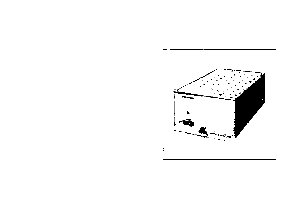
The Panasonic Video Distribution Amplifier, model
WJ-300C, was designed to distribute the color/
monochrome video signal. Incorporates a video input
selection switch, it enables the distribution of six (6)
isolated video outputs frorn one (1) video input or three
(3) each outputs from two (2) separated video inputs.
One (1) input for six (6) outputs or two (2) different
inputs for three (3) outputs each.
2.
High stability and durability in operation with new
circuitry.
3.
Rack mountable or table top use.
PRECAUTIONS
Keep power switch off while making cable
connections.
2.
Operate this unit within a temperature range of 14°F
to 122°F (—10°C ~ +50°C) and humidity is below
90*/..
Power source should be 120V AC, 60Hz.
Do not attempt to disassemble the unit. In order
to prevent electrical shock, do not remove covers.
There are no user-serviceable parts inside.
Do not use strong or abrasive detergents when
cleaning the unit. Do use a dry cloth to clean the
unit when dirty.
All necessary procedures with regard to the
installation of this product should be made by
qualified service personnel or system installers.
- 2 -
Page 4
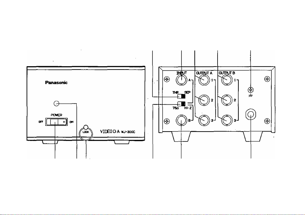
MAJOR OPERATING CONTROLS AND THEIR FUNCTIONS
5 6
1 2 3 11 10
-3-
Page 5

1. Power ON/OFF Switch (POWER ON/OFF)
2. Power Indicator
This indicator lights when the power switch is turned
on,
3. Handle/Lock Ring (LOCK)
This ring should be used when the unit is mounted
on the rack,
4. Input Selection Switch (THR/SEP)
This switch is used when selecting the input signal
from single input or dual input,
(a) THR position
When a single video signal is supplied to the
Input A Connector (5) or Input B Connector (10),
set this switch to THR position (Fig, 1). This will
provide six (6] identical and isolated outputs
to the Output A Connector (6) and the Output
B Connector (7), The Termination Switch (11)
should be set to 75ii position (Fig. 1),
THR SEP
75ii Hi-Z~]
Fig, 1
Note:
When bridging or looping through the input
signal, set the Termination Switch (11) to Hi-Z
position (Fig. 2).
THR SEP
i
75n Hi-Z I
Fig, 2
SEP position
(b)
When the two (2) different video signals are
supplied to the Input A Connector (5) and the
Input B Connector (10), set this switch to SEP
position (Fig, 3). This will provide three (3)
identical and isolated outputs to the Output A
Connector (6) and the Output B Connector (7)
for each input,
THR SEP
75fi Hi-Z^
Fig. 3 ■
-4 -
Page 6

Note:
When using SEP position for dual video input,
each input is automatically terminated with
75 ohms regardless of the setting up of the
Termination Switch (11).
5. Input A Connector (INPUT A)
A composite video signal should be supplied to this
connector.
Note:
Refer to the operation of the Input Selection
Switch (4) and the Termination Switch (11).
6. Output A Connector (OUTPUT A)
Three (3) identical and isolated video signals are
provided to these connectors.
Note:
Refer to the operation of the Input Selection
Switch (4).
7. Output B Connector (OUTPUT B)
Three (3) identical and isolated video signals are
provided to these connectors.
Note:
Refer to the operation of the Input Selection
Switch (4),
6. Ground Terminal
9. Power Cord
10. Input B Connector (INPUT B)
A composite video signal should be supplied to this
connector.
Note:
Refer to the operation of the Input Selection
Switch (4) and the Termination Switch (11).
11. Termination Switch (75i) Hi-Z)
When a single video signal is supplied to
either the Input A Connector (5) or the Input
B Connector (10), set this switch to T S Q
position.When bridging or looping through the
input signal among the Input A Connector (5)
and the Input B Connector (10), set this switch
to Hi-Z position.
Note:
When the Input Selection Switch (4) is set to
the SEP position for the dual input, the Input
A Connector (5) and the Input B Connector
(10) are automatically terminated with 75 ohms
regardless of the setting up of the Termination
Switch (11).
- 5 -
Page 7

CONNECTIONS
Note; Every output must be terminated with 75ii at the last connected video monitor.
1. One input • ” 6 outputs {no bridging, no looping through)
Video Monitor
6 outputs for
^ A video signal
- 6 -
Page 8

2. One input • • • 12 outputs using 2 Video D.As WJ-300C (bridging or looping through)
Video Monitor
Page 9

3. Two Inputs • • • 3 outputs each
Each video input is automatically terminated with 75 ohms regardless of the setting of the Termination Switch
(11).
Video Monitor
o S,
to to
Is
D S
O >
rt <
O S,
1- O)
« w
3 o
Q. d)
3 ^
o >
ro m
i_ «
.S'
-8-
Page 10

RACK MOUNTING
This Video DA can be mounted on the 19 inch rack
by utilizing the optional Rack Mount Frame and the
Blank Panels in the following procedure, The Rack
Mount Frame WJ-A01 requires 3-1/2 inches height in
a standard 19 inch rack.
Rack Mount Frame
1. Mount the Rack Mount Frame WJ-A01 on a rack,
2. Remove four rubber feet from the Video DA.
WJ-300C and turn the Handle/Lock Ring on the
front panel fully counterclockwise.
3. Slide Video D.A. and two Blank Panels WJ-B02 into
the Rack Mount Frame and turn the Handle/Lock
Ring fully counterclockwise to secure products.
Note:
- 9 -
Page 11

SPECIFICATIONS
Power Source:
Video Input:
Video Output:
Gain:
Differential Gain:
Differential Phase:
Frequency Response:
S/N:
Ambient Operating Temperature:
Ambient Operating Humidity:.
Power consumption;
Dimensions:
Weight:
Weights and dimensions shown are approximate.
Specifications are subject to change without notice.
120V AC, 60Hz
1.0Vp-p/75 ohms composite video signal (Maximum 2.0Vp-p)
1.0Vp-p/75 ohms composite video signal (Maximum 2.0Vp-p)
6 outputs for one input
3 outputs each for dual input
OdB
Less than 0.5'/.
Less than 0.5 degree
Within ±0.2dB at 8MHz
Within ±0.5dB at 10MHz
Greater than 60dB
14°F - 122°F (-10®C - +50®C)
Less than 90*/.
Approx. 0W
5-1/2" (W) X 3-1/2" (H) X 8-7/8" (D)
(140 (W) X 88(H) X 225(D) mm)
4.12 lbs (1.87kg)
- 10 -
Page 12

Panasonic
Communications & Systems Company
Division of Matsushita Electric Corporation of America
CLOSED CIRCUIT VIDEO EQUIPMENT DIVISION
Executive Offices: One Panasonic Way, Secaucus, New Jersey 07094
Regional OfftCM
Northeast Region:
Southeast Region:
Midwesi Region:
Southvrest Region:
Western Region:
MATSUSHITA ELECTRIC OF CANADA UMITED
5770 Ambler Drive, Mississauga, Ontario, Canada LAW 2T3 (416)624-5010
PANASONIC SALES COMPANY
DIVISION OF MATSUSHITA ELECTRIC OF PUERTO RICO, INC.
San Gabriel Iridustrial Park, 6Sth Infantry, Ave. KM. 9.5 Carolina. Puerto Rico 00630 (809) 750-4300
50 Meadowiand Parkway, Secaucus, NJ 07094 {201) 348-7303
1854, Shackieford Court, Suite 115, Norcross, QA 30093 (404)925-e835
425 E, AigoTKiuin Road, Arlington Heights, IL 60005 (708) 640-5168
4500 Amon Carter Btvd., Ft Worth. TX 76155 (817) 685-1117
6550 Katella Ave., Cypress, CA 90630 (714) 373-7265
N1290-0
YWV0QA2356AN
Printed in Japan
(N) 15
 Loading...