

Page 1

Voice Processing System
Installation Manual
V
O
IC
E
P
R
O
C
E
S
S
IN
G
S
Y
S
T
E
P
O
W
E
R
M
Model No.
KX-TVS90
Thank you for purchasing a Panasonic Voice Processing System, Model KX-TVS90.
Please read this manual before installing, customizing, or operating the Voice Processing System.
Page 2

Thank you for purchasing the Panasonic Model
KX-TVS90 Voice Processing System.
We are confident that it will provide your customer or client with many years of dependable
service.
This Voice Processing System was especially tailored for the American environment. For
example, it can be configured for English, a second language, or a third language:
System prompts—Recorded at the factory in English
User 1 prompts—Record in any language you like
User 2 prompts—Recorded at the factory in Spanish
These prompts guide subscribers and non-subscribers through specific VPS operations.
However, we would like to stress that for outside callers who merely need to be guided to an
extension, a mailbox, or other destinations (e.g., a fax machine), they can be greeted by a
Custom Service. This supports many languages as there are 12 keys on a touchtone phone and
you can record up to 100 Custom Service menus. One twelfth of these menus can be recorded
in one language if you desire. Another twelfth can be recorded in another language, and so on.
Thus callers can be guided entirely in their native languages. For a multi-cultural United States,
Custom Service is a truly powerful feature. Please see "Custom Service" in Appendix
A1 SYSTEM FEATURES for more details.
Note
This product is only for connection behind a suitable PBX and should not be connected directly
to the network.
Panasonic World Wide Web Address: http://www.panasonic.com
for customers in the United States or Puerto Rico.
2 Installation Manual
Page 3

Important Information
SAFETY REQUIREMENTS
• Follow all product warnings, cautions, and instructions.
• Handle the unit carefully. Do not drop or otherwise expose the unit to physical shock.
• If the unit malfunctions, disconnect the unit from the telephone line and check the line by
reconnecting the telephone. If the telephone operates properly, have the VPS repaired by a
qualified Panasonic Factory Service Technician.
• Install the unit so that the power cord is not obstructed in any way. Do not connect this unit
to an extension cord.
• Keep the unit free of dust, moisture, condensation, high temperature exposure (more than
40 °C {104 °F}) and vibration. Do not expose the unit to direct sunlight.
• Mount the unit on a stable wall surface. Do not mount the VPS inside of a separate
enclosure unless it is properly ventilated.
• Read all the information contained in this manual.
• This unit is designed to operate at one specific voltage and current setting. The proper
voltage and current required for this unit are listed on the product label.
• This unit is equipped with a 3-wire grounding plug. The plug will only fit into a grounded
power outlet. Do not modify this plug in any way. If it cannot be inserted into the outlet,
have the outlet replaced by a licensed electrician.
• Unplug and transport the unit to a service technician if the power supply cord is frayed or
damaged, if the cabinet is cracked or broken, or when the unit has been exposed to moisture,
has been dropped, or is not otherwise operating properly.
• Unplug the unit from its power source before cleaning.
• Do not block the vent slots and openings located on the front and top of the unit.
• Do not disassemble this product. Dangerous electrical shock could result. The unit must
only be disassembled and repaired by qualified Panasonic Factory Service Technicians.
• Do not insert wires, pins, or any other material into the unit's vent slots or access points.
This could result in electrical shock and serious unit malfunction.
• Do not install the unit near water or moisture, heating appliances, or electrical noise
generating devices such as televisions, monitors, fluorescent lamps, or electric motors.
• Do not overload wall outlets. Overloaded outlets could result in fire and/or electrical shock.
• Do not use solvents, liquid cleaners, water, or abrasive powders to clean this unit. Use only
a damp soft cloth for cleaning.
• Do not use the telephone during a lightning storm or to report a gas leak in the vicinity of
the leak.
Important Information
WARNING
TO PREVENT FIRE OR ELECTRICAL SHOCK, DO NOT EXPOSE THIS UNIT TO
RAIN OR MOISTURE.
Installation Manual 3
Page 4

Important Information
When you ship the product
Carefully pack and send it prepaid, adequately insured and preferably in the original carton.
Attach a postage-paid letter, detailing the symptom, to the outside of the carton. DO NOT
send the product to the Executive or Regional Sales offices. They are NOT equipped to
make repairs.
Product service
Panasonic Factory Servicenters for this product are listed in the servicenter directory.
Consult your authorized Panasonic dealer for detailed instructions.
The serial number of this product may be found on the label affixed to the back of the unit.
You should note the serial number of this unit in the space provided and retain this book as a
permanent record of your purchase to aid in identification in the event of theft.
MODEL NO.:
SERIAL NO.:
For your future reference
DATE OF PURCHASE
NAME OF DEALER
DEALER’S ADDRESS
DEALER’S TEL. NO.
WARNING
THIS UNIT MAY ONLY BE INSTALLED AND SERVICED BY QUALIFIED
SERVICE PERSONNEL.
WHEN A FAILURE OCCURS WHICH RESULTS IN THE INTERNAL PARTS
BECOMING ACCESSIBLE, DISCONNECT THE POWER SUPPLY CORD
IMMEDIATELY AND RETURN THIS UNIT TO YOUR DEALER.
DISCONNECT THE TELECOM CONNECTION BEFORE DISCONNECTING THE
4 Installation Manual
Page 5

Important Information
POWER CONNECTION PRIOR TO RELOCATING THE EQUIPMENT, AND
RECONNECT THE POWER FIRST.
THIS UNIT IS EQUIPPED WITH AN EARTHING CONTACT PLUG. FOR SAFETY
REASONS, THIS PLUG MUST ONLY BE CONNECTED TO AN EARTHING
CONTACT SOCKET WHICH HAS BEEN INSTALLED ACCORDING TO
REGULATIONS.
CAUTION
Danger of explosion if battery is incorrectly replaced.
Replace only with the same or equivalent type
recommended by the manufacturer.
Dispose of used batteries according to the
manufacturer's instructions.
Note
Before you start setting or changing system parameters, we recommend that you turn off the
Call Progression Mode with the OFLN command. While off, the power LED of the VPS will
flash and the VPS will not answer any incoming call. After you finish programming, use the
ONLN command to turn on the Call Progression Mode (normal operation). Please see
7.2.1 Off-line Set (OFLN) and 7.2.2 On-line Set (ONLN) for more details.
Trademarks
• HyperTerminal is either a registered trademark or a trademark of HILGRAEVE,
INCORPORATED in the United States and/or other countries.
• IBM is a trademark of International Business Machines Corporation in the United
States.
• Procomm Plus is either a registered trademark or a trademark of DATASTORM
TECHNOLOGIES, INC. in the United States and/or other countries.
• Smartcom is either a registered trademark or a trademark of Hayes Microcomputer
Products, Inc. in the United States and/or other countries.
• All other trademarks identified herein are the property of their respective owners.
Installation Manual 5
Page 6

Important Information
F.C.C. REQUIREMENTS AND RELEVANT INFORMATION
Notify The Telephone Company
This equipment complies with Part 68 of the FCC rules and the requirements adopted by the
ACTA. On the back of this equipment is a label that contains, among other information, a
product identifier in the format US:ACJVM04BKX-TVS90. If requested, this number must be
provided to the telephone company.
Installation must be performed by a qualified professional installer. If required, provide the
telephone company with the following technical information:
• The telephone numbers to which the system will be connected
• Make: Panasonic
• Model: KX-TVS90
• FCC Registration No.: found on the back of the unit
• Ringer Equivalence No.: 0.4B
• Facility Interface Code: 02LS2
• Service Order Code: 9.0F
• Required Network Interface Jack: RJ11C
Ringer Equivalence No. (REN)
The REN is used to determine the number of devices that may be connected to a telephone line.
Excessive RENs on a telephone line may result in the devices not ringing in response to an
incoming call. In most but not all areas, the sum of RENs should not exceed five (5.0). To be
certain of the number of devices that may be connected to a line, as determined by the total
RENs, contact the local telephone company. For products approved after July 23, 2001, the
REN for this product is part of the product identifier that has the format US:ACJVM04BKXTVS90. The digits represented by ## are the REN without a decimal point (e.g., 03 is a REN
of 0.3). For earlier products, the REN is separately shown on the label.
Telephone Service Problems
If this equipment causes harm to the telephone network, the telephone company will notify you
in advance that temporary discontinuance of service may be required. But if advance notice
isn't practical, the telephone company will notify the customer as soon as possible. Also, you
will be advised of your right to file a complaint with the FCC if you believe it is necessary.
Changes in Telephone Company Communications Facilities, Equipment, Operations,
and Procedures
The telephone company may make changes in its facilities, equipment, operations or
procedures that could affect the operation of the equipment. If this happens the telephone
company will provide advance notice in order for you to make necessary modifications to
maintain uninterrupted service.
Trouble with this equipment
If trouble is experienced with this equipment, for repair or warranty information, please see the
attached warranty, which includes the Servicenter Directory. If the equipment is causing harm
6 Installation Manual
Page 7

Important Information
to the telephone network, the telephone company may request that you disconnect the
equipment until the problem is resolved.
Connection to the Party Line
Connection to party line service is subject to state tariffs. Contact the state public utility
commission, public service commission or corporation commission for information.
Note
This equipment has been tested and found to comply with the limits for a Class B digital
device, pursuant to Part 15 of the FCC Rules. These limits are designed to provide
reasonable protection against harmful interference in a residential installation. This
equipment generates, uses and can radiate radio frequency energy and, if not installed
and used in accordance with the instructions, may cause harmful interference to radio
communications. However, there is no guarantee that interference will not occur in a
particular installation. If this equipment does cause harmful interference to radio or
television reception, which can be determined by turning the equipment off and on, the
user is encouraged to try to correct the interference by one or more of the following
measures.
— Reorient or relocate the receiving antenna.
— Increase the separation between the equipment and receiver.
— Connect the equipment into an outlet on a circuit different from that to which
the receiver is connected.
— Consult the dealer or an experienced radio/TV technician for help.
CAUTION
Any change or modification made to the terminal equipment, not expressly approved by the
manufacturer, could void the user's authority to operate this equipment.
Installation Manual 7
Page 8

Table of Contents
Table of Contents
1 VOICE PROCESSING SYSTEM OVERVIEW
1.1 WHAT THE VPS CAN AND CANNOT DO............................................................ 14
1.1.1 Why Voice Processing?.............................................................................................. 14
1.1.2 Basic Operations......................................................................................................... 14
1.1.3 VPS Limitations ......................................................................................................... 15
1.2 SYSTEM ADMINISTRATION, MANAGEMENT, AND USE.............................. 16
1.2.1 System Administration ............................................................................................... 16
1.2.2 System Management .................................................................................................. 16
1.2.3 Subscriber Use............................................................................................................ 16
1.3 SYSTEM BASICS ....................................................................................................... 17
1.3.1 General ....................................................................................................................... 17
1.3.2 System Components ................................................................................................... 17
1.3.3 Which Phone Systems are Compatible?..................................................................... 19
1.3.4 Installer Equipment and Software Requirements ....................................................... 20
1.3.5 Specifications .............................................................................................................21
1.3.6 Hardware .................................................................................................................... 21
1.3.7 Recommendations for System Configuration ............................................................ 21
1.4 DIGITAL INTEGRATION ........................................................................................ 23
1.4.1 General ....................................................................................................................... 23
1.4.2 APT Integration .......................................................................................................... 23
1.4.3 Connection Example—APT Integration .................................................................... 23
1.4.4 DPT Integration .......................................................................................................... 24
1.4.5 Connection Example—DPT Integration .................................................................... 24
2 INSTALLATION
2.1 SAFETY PRECAUTIONS ......................................................................................... 26
2.1.1 Installation .................................................................................................................. 26
2.1.2 Wiring......................................................................................................................... 27
2.2 UNPACKING .............................................................................................................. 28
2.3 MOUNTING THE VPS ON THE WALL................................................................. 29
2.4 FRAME GROUND CONNECTION ......................................................................... 30
2.5 INSTALLATION STEPS ........................................................................................... 31
2.6 CONNECTIONS ......................................................................................................... 33
2.6.1 Connecting to the PBX............................................................................................... 33
2.6.2 Opening the Ferrite Core............................................................................................ 33
2.6.3 Connection for APT Integration................................................................................. 34
2.6.4 Connection for DPT Integration................................................................................. 34
2.6.5 Connection for Non-APT/DPT Integration................................................................ 35
2.7 TERMINAL CONNECTION..................................................................................... 36
2.7.1 Requirements for Connecting Programming Terminal .............................................. 36
2.7.2 Connecting the RS-232C Cable.................................................................................. 36
2.7.3 RS-232C Signals ........................................................................................................ 38
3 INTEGRATING THE VPS WITH PANASONIC KX-T PHONE
SYSTEMS
3.1 GUIDELINES FOR INTEGRATION....................................................................... 40
8 Installation Manual
Page 9

Table of Contents
3.1.1 APT/DPT or Inband Signaling?..................................................................................40
3.1.2 Why Integration is Important ......................................................................................40
3.1.3 How the VPS and the PBX Communicate..................................................................40
3.1.4 PBX Requirements for Integration..............................................................................41
3.2 PBX PARAMETERS AND PORT SETTINGS ........................................................44
3.2.1 General Guidelines and Definitions ............................................................................44
3.2.2 RS-232C Settings ........................................................................................................44
3.2.3 Port Settings ................................................................................................................44
3.2.4 PBX Interface Parameters ...........................................................................................45
3.3 CONNECTING THE VPS WITH PANASONIC KX-T SERIES PBXs ................48
3.3.1 VPS Programming for Inband Integration ..................................................................48
3.3.2 KX-T123211D Software Verification and Programming for Inband Integration.......49
3.3.3 KX-TA Series Programming for Inband Integration via the Manager’s Extension....51
3.3.4 KX-TD500 Programming for Inband Integration .......................................................54
3.3.5 KX-TD816, KX-TD1232, KX-TA1232 and KX-TD308 Programming for Inband
Integration via the Manager’s Extension ...................................................................63
3.3.6 KX-TD816, KX-TD1232, and KX-TA1232 Programming for Inband Integration via
the Operating and Maintenance Tool.........................................................................64
3.3.7 KX-TD308 Programming for Inband Integration via the Operating and Maintenance
Tool............................................................................................................................67
4 INTEGRATING THE VPS WITH THE PANASONIC KX-TA
SERIES PBX AND KX-TD SERIES PBX
4.1 GUIDELINES FOR DIGITAL INTEGRATION .....................................................72
4.1.1 Why Digital Integration is Important ..........................................................................72
4.2 CONNECTING THE VPS WITH THE PANASONIC KX-TA624 ........................74
4.2.1 KX-TA624 Software Verification and Programming for Digital Integration via the
Manager’s Extension .................................................................................................74
4.3 KX-TD500 PROGRAMMING FOR DIGITAL INTEGRATION ..........................80
4.4 CONNECTING THE VPS WITH THE PANASONIC KX-TD816, KX-TD1232,
KX-TA1232 AND KX-TD308 ....................................................................................88
4.4.1 KX-TD1232 Software Verification and Programming for DPT Integration via the
Manager’s Extension .................................................................................................88
4.4.2 KX-TD1232 Software Verification and Programming for DPT Integration via the
Operating and Maintenance Tool...............................................................................93
4.4.3 KX-TD308 Software Verification and Programming for DPT Integration via the
Manager’s Extension .................................................................................................96
4.5 COMMON DIGITAL INTEGRATION FEATURES AND SETUP PROCEDURES........ 101
4.5.1 Live Call Screening (LCS) Programming .................................................................101
4.5.2 Live Call Screening Password Assignment ..............................................................101
4.5.3 Live Call Screening Password Canceling .................................................................102
4.5.4 Live Call Screening Recording Mode Assignment via System Programming.........102
4.5.5 Live Call Screening Private/Hands-Free Mode Assignment via Station Programming ........... 103
4.5.6 Live Call Screening Assignment via PC Programming ............................................104
4.5.7 Live Call Screening Button Assignment via Station Programming..........................105
4.5.8 Live Call Screening Cancel Button Assignment via Station Programming..............105
4.5.9 Two-Way Recording Button Assignment via Station Programming........................106
4.5.10 Two-Way Transfer Button Assignment via Station Programming.........................107
4.5.11 Voice Mail Transfer Button Assignment via Station Programming.......................108
Installation Manual 9
Page 10

Table of Contents
4.5.12 Button Assignment via PC Programming .............................................................. 108
4.5.13 Live Call Screening Activation .............................................................................. 110
4.5.14 Live Call Screening Password Control................................................................... 111
4.5.15 Two-Way Recording into Mailbox ........................................................................ 111
4.5.16 Two-Way Transfer into Mailbox............................................................................ 111
4.5.17 A Restriction on TWR/TWT Activation ................................................................ 111
5 CUSTOMIZING THE SYSTEM
5.1 STARTING UP .......................................................................................................... 114
5.1.1 Before Programming ................................................................................................ 114
5.1.2 Quick Setup .............................................................................................................. 114
5.1.3 Starting the Quick Setup........................................................................................... 115
5.2 PORT SETTING OPTIONS .................................................................................... 122
5.2.1 Custom Service Setting Example............................................................................. 122
5.2.2 Custom Service Features .......................................................................................... 123
5.2.3 Custom Service Programming.................................................................................. 124
5.2.4 Recording Menus...................................................................................................... 128
5.2.5 Checking Operation.................................................................................................. 128
5.2.6 Voice Mail ................................................................................................................ 128
5.2.7 Mailbox Groups........................................................................................................ 129
5.2.8 Extension Groups ..................................................................................................... 129
5.2.9 Interview Service...................................................................................................... 130
5.2.10 Automated Attendant.............................................................................................. 131
5.2.11 Department Dialing Service ................................................................................... 131
5.2.12 Operator Service..................................................................................................... 132
5.3 SETTING PORTS ..................................................................................................... 133
5.3.1 Port Service Menu .................................................................................................... 133
5.4 AUTOMATED ATTENDANT PARAMETERS.................................................... 135
5.4.1 Automated Attendant Menu ..................................................................................... 135
5.4.2 Department Dialing .................................................................................................. 135
5.4.3 Operator’s Parameters .............................................................................................. 136
5.5 SETTING MAILBOXES .......................................................................................... 139
5.5.1 Mailbox Setting Menu.............................................................................................. 139
5.5.2 Entering a Mailbox................................................................................................... 139
5.5.3 Deleting a Mailbox................................................................................................... 143
5.5.4 Password Reset......................................................................................................... 143
5.5.5 Mailbox Listing ........................................................................................................ 144
5.6 TRAINING THE SUBSCRIBER............................................................................. 145
6FINAL SETUP
6.1 MESSAGE MANAGER'S MAILBOX (Mailbox 998)........................................... 148
6.1.1 Accessing the Message Manager’s Mailbox ............................................................ 148
6.1.2 Main Menu of Message Manager’s Service ............................................................. 148
6.1.3 Company Greetings (Enter #6*998,5,1)................................................................... 149
6.1.4 Recording the Company Name (Enter #6*998,5,2) ................................................. 149
6.1.5 Custom Service Greetings (Enter #6*998,5,4)......................................................... 149
6.1.6 Customizing User Prompts (Enter #6*998,5,6) ....................................................... 150
6.2 SETTING UP MAILBOXES.................................................................................... 151
6.2.1 Recording Personal Greetings.................................................................................. 151
10 Installation Manual
Page 11

Table of Contents
6.2.2 Recording the Owner’s Name...................................................................................152
6.3 BACKING UP THE SYSTEM..................................................................................153
7 SYSTEM MAINTENANCE AND TROUBLESHOOTING
7.1 INITIALIZING THE SYSTEM ...............................................................................156
7.2 UTILITY COMMANDS............................................................................................158
7.2.1 Off-line Set (OFLN)..................................................................................................159
7.2.2 On-line Set (ONLN)..................................................................................................159
7.2.3 Set Password (PASS) ................................................................................................159
7.2.4 Set Time (TIME).......................................................................................................160
7.2.5 Print Reports at Specified Time (PSET) ...................................................................161
7.2.6 Error Log Display (ELOG) .......................................................................................162
7.2.7 Saving the System Data to the Backup Device (SAVE)...........................................164
7.2.8 Loading New or Saved Data to the VPS (LOAD) ....................................................166
7.2.9 Print All of the VPS Parameters (GPRN) .................................................................167
7.2.10 Program Version Display (VERS) ..........................................................................167
7.2.11 Custom Service Report (CREP)..............................................................................168
7.2.12 Custom Service Menu Access Count Clear (CCLR) ..............................................169
7.2.13 Message Waiting Lamp Retry Times (MWL) ........................................................169
7.2.14 Setting Minimum Recording Length (MRL) ..........................................................170
7.2.15 Modified Prompt List (MPLT)................................................................................170
7.2.16 Utility Command List (HELP)................................................................................171
7.2.17 Quick Setup (QSET) ...............................................................................................172
7.2.18 Circuit Condition Display (LMON) ........................................................................172
7.2.19 Touchtone Information Display (PUTD) ................................................................172
7.2.20 Wait for Caller ID (WCID) .....................................................................................174
7.3 SYSTEM REPORTS..................................................................................................175
7.3.1 Mailbox Assignments................................................................................................176
7.3.2 COS (Class of Service) Assignments........................................................................176
7.3.3 System Service Report ..............................................................................................178
7.3.4 Call Account Report..................................................................................................178
7.3.5 Port Usage Report .....................................................................................................179
7.3.6 Port Usage Statistics Clear........................................................................................179
7.3.7 Flash Memory Usage Report.....................................................................................180
7.3.8 Flash Memory Usage Statistics Clear .......................................................................181
7.3.9 Mailbox Usage Report ..............................................................................................181
7.3.10 Mailbox Usage Statistics Clear ...............................................................................182
7.3.11 Fax Call Report .......................................................................................................183
7.3.12 Fax Call Statistics Clear..........................................................................................183
7.4 TROUBLESHOOTING GUIDE ..............................................................................184
7.5 SPECIFICATIONS....................................................................................................188
Appendix A SYSTEM FEATURES
A1 SYSTEM FEATURES ...............................................................................................190
Appendix B SYSTEM ADMINISTRATOR'S GUIDE
B1 SYSTEM NAVIGATION ..........................................................................................220
B2 SYSTEM ADMINISTRATION—MAILBOXES ....................................................224
Installation Manual 11
Page 12

Table of Contents
B3 SYSTEM ADMINISTRATION—SETTING COS (CLASS OF SERVICE)
PARAMETERS........................................................................................................ 231
B4 SYSTEM ADMINISTRATION—PORT/TRUNK SERVICE .............................. 241
B4.1 Port Assignment........................................................................................................ 241
B4.2 Trunk Group Assignment ......................................................................................... 243
B5 SYSTEM ADMINISTRATION—SERVICE SETTINGS..................................... 246
B5.1 Automated Attendant Parameters............................................................................. 246
B5.2 Custom Service ......................................................................................................... 254
B5.3 Caller ID Call Routing Parameters........................................................................... 257
B6 SYSTEM ADMINISTRATION—SYSTEM PARAMETER SETTINGS ........... 260
B6.1 System Group Assignment ....................................................................................... 260
B6.2 Time Service ............................................................................................................. 263
B6.3 Holiday Setting ......................................................................................................... 267
B6.4 Daylight Saving Time (DST).................................................................................... 269
B6.5 Prompt Setting .......................................................................................................... 270
B6.6 System Caller Name Announcement........................................................................ 272
B6.7 Other Parameters....................................................................................................... 273
B7 SYSTEM ADMINISTRATION—HARDWARE SETTINGS .............................. 285
B7.1 RS-232C Parameters................................................................................................. 285
B7.2 Port Setting ............................................................................................................... 286
B7.3 PBX Interface Parameters......................................................................................... 287
Appendix C SYSTEM MANAGER'S GUIDE
C1 ACCESSING THE SYSTEM MANAGER'S MAILBOX ..................................... 296
C2 SETTING UP MAILBOXES.................................................................................... 297
C3 SETTING COS (CLASS OF SERVICE) PARAMETERS ................................... 300
C4 SETTING THE SYSTEM CLOCK ......................................................................... 307
C5 CHANGING THE SERVICE MODE SETTING .................................................. 309
C6 CHANGING THE COMPANY GREETING SETTING ...................................... 311
C7 CHECKING SYSTEM USAGE (SYSTEM REPORTS)....................................... 313
C8 DELIVERING MESSAGES..................................................................................... 315
C9 CUSTOMIZING THE SYSTEM MANAGER'S MAILBOX ............................... 318
C10 LISTENING TO SYSTEM MANAGER MESSAGES ........................................ 319
Appendix D MESSAGE MANAGER'S GUIDE
D1 ACCESSING THE MESSAGE MANAGER'S MAILBOX .................................. 322
D2 MANAGING THE GENERAL DELIVERY MAILBOX ..................................... 323
D3 SETTING UP MESSAGE WAITING NOTIFICATION...................................... 325
D4 CUSTOMIZING THE MESSAGE MANAGER'S MAILBOX ............................ 328
D5 SETTING THE SYSTEM CLOCK ......................................................................... 330
D6 RECORDING MESSAGES...................................................................................... 332
D7 REMOTE CALL FORWARDING SET ................................................................. 337
D8 LIST OF PROMPTS FOR VOICE MAIL AND AA SERVICE .......................... 340
D9 LIST OF MODIFIABLE PROMPTS...................................................................... 343
Glossary ............................................................................................... 395
INDEX.................................................................................................. 407
12 Installation Manual
Page 13

VOICE PROCESSING SYSTEM OVERVIEW
Section 1
VOICE PROCESSING SYSTEM OVERVIEW
Installation Manual 13
Page 14

VOICE PROCESSING SYSTEM OVERVIEW
1.1 WHAT THE VPS CAN AND CANNOT DO
1.1.1 Why Voice Processing?
The VPS handles incoming and outgoing calls. When a call comes in, it answers, forwards to
appropriate extensions, takes and stores messages, and notifies subscribers when messages are
left. Subscribers may send and transfer messages to other subscribers within the system. The
VPS is easy to use, helping callers through the system with step-by-step voice prompts.
Unlike handwritten messages or those left with answering services, VPS messages are
confidential; they are stored in a mailbox and retrieved only with the subscriber's password.
Other advantages of the VPS are clarity and accuracy, which are commonly lacking with
written messages. The messages come directly from the caller, in the caller's own voice. To
further ensure accuracy, the system allows the sender to correct or change messages before
saving them. Messages can be erased or transferred by the recipient.
1.1.2 Basic Operations
Greeting Callers:
The VPS greets callers with a prerecorded message that includes directions for leaving and
editing messages. The VPS can list single-digit numbers for each available extension or
mailbox. Callers who know the extension of the person they wish to reach may dial the
extension number at any time. Callers with rotary phones are transferred to a preprogrammed
destination (which is often an operator or the General Delivery Mailbox) to leave a message.
Sending Messages:
Callers can review and edit messages before leaving them in a mailbox. Subscribers can send
messages to an individual or to several mailboxes at once. The message sender can then verify
that the other subscriber has received the message.
Receiving Messages:
There are several different message notification methods that subscribers can use. They can
choose to be notified by message waiting lamp, beeper, or a call from the system to another
line. System programming determines whether a subscriber will be notified each time a
message is left. (Subscribers can choose to receive message notifications differently depending
on the time of day.) Mailbox parameters, which accommodate 5-100 messages, determine the
maximum length of messages. If the system is connected using Digital Integration, subscribers
can press a pre-assigned button to record conversations into their own mailboxes or other
subscribers' mailboxes while talking on the phone. Digital Integration also allows subscribers
to screen messages as they are being left, or intercept them if required.
14 Installation Manual
Page 15

1.1.3 VPS Limitations
The VPS does not support:
UCD functions
UCD (Uniform Call Distribution) is a service that distributes calls evenly among extensions;
when all extensions are unavailable, it returns to callers to say that all extensions are busy.
Calls can be forwarded by the VPS to the KX-TD1232/816/308/500 floating number of a UCD
group. The call then rings at the next available phone.
The VPS supports UCD functions with very limited capabilities. Because the incoming call
is forwarded as an intercom path and not a DIL (direct in line), the following items will not
work:
• time table
• overflow function
• DISA message from a DISA card
• IRNA
VOICE PROCESSING SYSTEM OVERVIEW
Integration with the wrong PBX or with certain Key Systems presents limitations to the VPS'
standard functions. We do not recommend these systems for integration with the VPS. The
section 1.3.3 Which Phone Systems are Compatible? explains problems with compatibility.
Installation Manual 15
Page 16

VOICE PROCESSING SYSTEM OVERVIEW
1.2 SYSTEM ADMINISTRATION,
MANAGEMENT, AND USE
1.2.1 System Administration
System Administration is accomplished by the installer using terminal emulation software. It
concerns setting and changing system parameters and diagnosing system problems.
1.2.2 System Management
Two system functions are performed by the customer: System Management and Message
Management.
System Management concerns changing system parameters through the System Manager's
Mailbox.
Message Management concerns recording voice prompts through the Message Manager's
Mailbox. These messages include Company Greetings, Company Name, Department Dialing
menu, Custom Service menus, voice labels for System Group Distribution Lists, user prompts,
multilingual selection menu and System Caller Names.
1.2.3 Subscriber Use
System users are called subscribers. Subscribers are assigned personal mailboxes which they
can customize. Subscribers can record their names, record personal greetings, set covering
extensions, record questions for an interview mailbox, set the message reception mode, set
incomplete call handling status, set call transfer status, enter Personal Group Distribution Lists,
set the message waiting lamp, and set notification by calling.
16 Installation Manual
Page 17
1.3 SYSTEM BASICS
1.3.1 General
The KX-TVS90 is initially configured with 2 ports and 6 h of storage.
1.3.2 System Components
Main Cabinet
AC Inlet
P
O
W
E
Power Indicator
R
VOICE PROCESSING SYSTEM OVERVIEW
MODE (DIP Switch)
Port 1
Port 2
V
O
I
C
E
P
R
O
C
E
S
S
I
N
G
S
Y
S
T
E
M
Ferrite Core
Ground Terminal
RS-232C
Connector
Note
EIA port is at SELV.
Inside View of the Main Cabinet
Memory Card
Slave
Master
System Components
AC Inlet:
Connects the power cable to an AC outlet dedicated to the VPS.
Power Indicator:
Indicates the system status: when flashing, the system is off-line (not ready to receive calls).
Installation Manual 17
Page 18
VOICE PROCESSING SYSTEM OVERVIEW
MODE (DIP Switch):
By setting one of the following positions and executing power down and up, you can achieve
a desired result:
Position Additional Function
01
•1
01
0 Normal setting. (All switches in 0 position.)
1
1
2*
1
3*
•2
01
•3
01
•4
01
•1
Initializes RS-232C parameters.
01
•2
01
•3
01
•4
RS-232C default parameters: 9,600, N, 8, 1
01
•1
Auto Configuration is automatically executed and all ports are
01
•2
01
•3
01
set for Automated Attendant service.
•4
01
•1
Auto Configuration is automatically executed and all ports are
01
•2
01
•3
01
•4
set for Voice Mail service.
4Reserved.
01
1•
Initializes the VPS. Clears all voice data (except User 1 and
01
2•
01
5
3•
User 2 prompts) and returns all system parameters to the default
01
4•
setting.
Table 1
01
1•
01
6 Test Mode (Flash Memory Read/Write Test)
2•
01
3•
01
4•
7Reserved.
01
1•
Initializes the VPS. Clears all voice data and returns all system
01
2•
01
3•
01
8
4•
parameters to the default setting.
CAUTION: User 1 and User 2 Prompts will be erased!
9Reserved.
01
•1
Auto Configuration is automatically executed and all ports are
01
2
10*
2
11*
12 All service prompts are set to System Prompts.
13 All service prompts are set to User 1 Prompts.
14 All service prompts are set to User 2 Prompts.
•2
01
•3
01
set for Automated Attendant service.
•4
01
•1
Auto Configuration is automatically executed and all ports are
01
•2
01
•3
01
set for Voice Mail service.
•4
01
1•
01
2•
01
3•
01
4•
01
1•
01
2•
01
3•
01
4•
01
1•
01
2•
01
3•
01
4•
15 Reserved.
1
For Panasonic KX-T series telephone systems with DPT Integration.
*
2
For Panasonic KX-TA624 telephone system with APT Integration.
*
18 Installation Manual
Page 19

VOICE PROCESSING SYSTEM OVERVIEW
To change the position, use a pointed object, such as a pen, etc.
When setting the DIP Switch to any position (except 0):
1. Disconnect the station wire(s) and wait a few minutes.
2. Disconnect the AC cord from the VPS.
3. Set the DIP Switch.
4. Connect the AC cord to the VPS.
5. Connect the station wire(s) to the VPS and wait approximately 3.5 min.
6. Return the DIP Switch to position 0.
Ground Terminal:
Should be connected to a ground source with less than 1 resistance.
RS-232C Connector:
Connects an ASCII or VT terminal to the VPS that is necessary to program the system.
Memory Card:
(One/system) Stores the proprietary system program, and the voice prompts (about 30 min
worth); has the capacity to record approximately 6h of messages from callers.
1.3.3 Which Phone Systems are Compatible?
We recommend integration with the following Panasonic phone systems:
• Panasonic KX-TA624
• Panasonic KX-TD308
• Panasonic KX-TD1232
• Panasonic KX-TD816
• Panasonic KX-TA1232
• Panasonic KX-TD500
• Panasonic KX-T336
• Panasonic KX-T123211D
We cannot guarantee adequate integration of the VPS with other PBX systems or with Key
Systems. If the customer does not have a recommended Panasonic PBX system, be sure that
the system has the features listed below.
The PBX should have the following features for successful integration:
• Single line (tip/ring) port circuits (Some PBXs need an OPX card to provide this
connection.)
• Station to station touchtone signaling
• Message Waiting Notification from an SLT (single-line telephone)
Installation Manual 19
Page 20

VOICE PROCESSING SYSTEM OVERVIEW
• Screened transfer from an SLT
• Message Waiting Notification on proprietary (multi-line) sets (message waiting lamp
accessed by dialing on/off codes)
If the PBX does not have these features, VPS operation will be limited.
See 3.1.4 PBX Requirements for Integration. You will find the following information about
each feature listed:
• Description
• Limitations of the system without the feature
• Tests to determine whether the PBX has the feature
VOICE MAIL
The recommended Panasonic PBX systems have Follow-on ID and Inband Integration. When
callers are transferred to an extension that is forwarded to Voice Mail, Follow-on ID sends
callers directly to the mailbox. Without Follow-on ID, the caller would have to re-enter the
mailbox number when connected to Voice Mail.
Touchtone Integration enables the VPS to recognize the current state of the call and improve
its call handling performance. When enabled, the PBX informs the VPS of the status of the call
(busy, answered, ringing, etc.) by sending a code with touchtones before sending the normal
call progress tones. For example, when a caller hangs up before making a selection, the PBX
sends # 9 to the VPS port that answered. This informs the VPS that the caller has hung up.
Upon receiving these digits, the VPS goes on-hook and is ready to handle another call.
Digital (APT/DPT) Integration is available when the VPS is connected to a Panasonic KXTA624 or other Panasonic KX-T series digital PBX (depending on the software version). This
Digital Integration provides the VPS with more information than Touchtone Integration. This
information enables the system to identify the extension number of the caller, know where
from and why the call is forwarded, and recognize what the caller wants to do. Some features
are available only with Digital Integration (Remote Call Forwarding Set, Live Call Screening,
Two-Way Recording, Two-Way Transfer, Direct Mailbox Access, Intercom Paging, Auto
Configuration, Caller Name Announcement [system/personal], Caller ID Call Routing,
Personal Greeting for Caller ID, Time Synchronization with PBX).
1.3.4 Installer Equipment and Software Requirements
The installer must have a personal computer or data terminal equipped with terminal
emulation software. We suggest that you use something like HyperTerminal by HILGRAEVE.
Use the personal computer to program the VPS. Terminal emulation software enables the
keyboard to be used as a data entry device.
While both the personal computer and data terminal are working, the personal computer allows
screens to be saved in a file throughout the process. It is often helpful to retrieve these files later
if technical support is needed.
20 Installation Manual
Page 21

1.3.5 Specifications
Voice Storage (approximate): 6 h
Number of Mailboxes: 62 Subscriber and 2 Manager Mailboxes
Number of Messages per Mailbox: 100 maximum (programmable)
1.3.6 Hardware
• 2 Flash Memory Cards.
• 2 Telephone Inputs (RJ11C)
• 1 RS-232C Connector
• 1 DIP Switch (4-bit)
VOICE PROCESSING SYSTEM OVERVIEW
Table 2
Ports: 2 ports
Custom Services: 100
Message Retention: 1 to 30 days or unlimited
1.3.7 Recommendations for System Configuration
General guideline: a ratio of 6/1 (for every 6 lines, 1 port). There are 2 questions to ask when
considering how many ports are desirable:
• Are the ports answering all incoming calls or just forwarded/transferred calls?
• If they are answering incoming calls, how busy are the lines?
The guideline above (6/1) usually works well with moderate traffic. However, this may have
to be modified for heavy traffic. Recommendations are outlined in the following charts.
Table 3
CO Lines Port
1-6 1
7-12 2
Installation Manual 21
Page 22

VOICE PROCESSING SYSTEM OVERVIEW
One port may not support an Automated Attendant configuration with 5 CO lines. The
preceding recommendations for Automated Attendant ports may have to be modified for heavy
traffic.
CO Lines Port
1-4 1
5-8 2
Table 4
22 Installation Manual
Page 23
1.4 DIGITAL INTEGRATION
1.4.1 General
There are 2 types of Digital Integration: APT Integration and DPT Integration.
APT Integration is available when the VPS is connected to a KX-TA624. DPT Integration is
available when the VPS is connected to a KX-TD or KX-TA1232 digital PBX.
1.4.2 APT Integration
To the Panasonic KX-TA624, the VPS ports look like proprietary telephones. The PBX thinks
that the VPS is a proprietary telephone, and the VPS mimics all actions of a proprietary
telephone. Communication between the VPS and the PBX through digital integration requires
the proper software level in the PBX and 4-wire connections for each port. To communicate
between the VPS and the PBX through APT Integration, the PBX and VPS must be
programmed to work together.
VOICE PROCESSING SYSTEM OVERVIEW
1.4.3 Connection Example—APT Integration
For example, you can connect jack 7 of the KX-TA624 to Port 1 of the VPS with a 4-wire
connection (see diagram below). This connection creates 1 Voice Mail extension and can only
answer 1 call. This means that a fully-configured 2-port system requires 2 jacks from the PBX.
VPS
KX-TA624
When APT Integration is activated, a single extension jack provides 1 single-line interface at
a Port on the VPS. For example, when 1 line cord (4 wire) is connected to Port 1 on the VPS,
1 extension is provided.
7
8
Port 1
Extension 107
Port 2
Extension 108
Installation Manual 23
Page 24
VOICE PROCESSING SYSTEM OVERVIEW
1.4.4 DPT Integration
To the Panasonic KX-T series PBX that uses DPT Integration, the VPS ports look like digital
extensions. The PBX thinks that the VPS is a digital phone, and the VPS mimics all actions of
a digital set. Another advantage of digital integration is that the 2B+D communication provides
2 VPS ports for each Digital Station port. Communication between the VPS and the PBX
through digital integration requires the proper software level in the PBX and 4-wire
connections for each port. To communicate between the VPS and the PBX through DPT
Integration, the PBX and VPS must be programmed to work together.
1.4.5 Connection Example—DPT Integration
For example, you can connect jack 15 of the KX-TD1232 to Port 1 of the VPS with a 4-wire
connection (see diagram below). This connection creates 2 Voice Mail extensions and can
simultaneously answer 2 calls. This means that a fully-configured 2-port system requires only
1 jack from the PBX.
VPS
KX-TD1232
When DPT Integration is activated, a single extension jack provides 2 single-line interfaces at
a Port on the VPS. For example, when 1 line cord (4 wire) is connected to Port 1 on the VPS,
2 extensions are provided.
15
Port 1
Extensions 165 and 166
24 Installation Manual
Page 25

INSTALLATION
Section 2
INSTALLATION
Installation Manual 25
Page 26

INSTALLATION
2.1 SAFETY PRECAUTIONS
Please read the following precautions before installing the VPS.
2.1.1 Installation
The VPS needs to be mounted on a wall. Improper placement of the system may result in
malfunction, noise, or discoloration. Avoid installing the VPS in the following places:
• in direct sunlight; in hot, cold, or humid places
• in new areas where there are thermal springs, etc. (where sulfuric gas may damage the
equipment or contacts).
• where shocks or vibrations are frequent or strong.
• in dusty places or places where water or oil may come in contact with the unit.
• near high frequency generating devices such as sewing machines, elevators or electric
welders.
• on or near computers, telexes, or other office equipment; near microwave ovens or air
conditioners. (Ideally, the VPS should not be in the room with these items and should be
at least 1.8 m {6 feet} away from televisions.)
Do not obstruct the areas around the PBX and the VPS. Both require space above for cooling
and space on the sides for maintenance and inspection.
26 Installation Manual
Page 27

2.1.2 Wiring
• To assure good quality telephone connection, it is recommended new and modifications to
existing installation of customer premise wiring shall use solid twisted pair copper
conductors with minimum 24 gauge that comply with the electrical specifications for
Category 3 wiring as detailed in ANSI/EIA/TIA-570A Building Wiring Standards.
• Do not wire the telephone cable parallel to an AC power source, computer, etc. If cables
are run near those wires, shield them with metal tubing or use shielded cables and ground
the shields.
• Use protectors if running cables on the floor. Avoid running cables under carpets.
• Avoid sharing a 120 V AC power supply for computers, telexes, and other office equipment
with the VPS. Induction noise from such equipment may interrupt the VPS operation.
When making any connections or removing the cover, be sure the power switch is turned off.
When installing telephone wiring, basic safety precautions should always be followed to
reduce the risk of fire, electric shock and injury to persons, including the following:
• Never install telephone wiring during a lightning storm.
• Never install telephone jacks in wet locations unless the jack is specifically designed for
wet locations.
• Never touch uninsulated telephone wires or terminals unless the telephone line has been
disconnected at the network interface.
• Use caution when installing or modifying telephone lines.
INSTALLATION
Note
If you live in an area that can have frequent power failures, we strongly recommend that you
purchase a suitable UPS (uninterruptible power supply) for your VPS (and PBX if needed).
The power rating of your VPS may be found in the specifications.
Installation Manual 27
Page 28

INSTALLATION
2.2 UNPACKING
Unpack the box and check the items below.
Table 5
Main Unit 1
AC Cord 1
Screws (Wall Mounting) 3
Anchor Plugs (Wall Mounting) 3
28 Installation Manual
Page 29
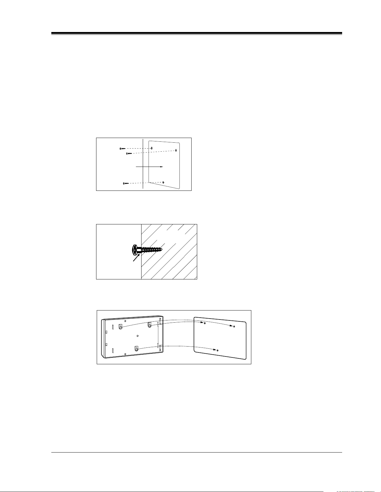
2.3 MOUNTING THE VPS ON THE WALL
The wall where the VPS is to be mounted must be able to support the weight of the VPS. If
screws other than the ones supplied are used, use the same-sized diameter screws as the
enclosed ones.
To Mount on a Wooden Wall:
1. Place the template (included) on the wall to mark the 3 screw positions.
Template
INSTALLATION
2. Install the 3 screws (included accessories) into the wall.
Wooden
Wall
Drive the screw
to this position.
3. Hook the unit on the screw heads.
Installation Manual 29
Page 30
INSTALLATION
2.4 FRAME GROUND CONNECTION
IMPORTANT!!!
Connect the frame of the main unit to the ground.
1. Loosen the screw.
2. Insert the grounding wire.
3. Tighten the screw.
4. Connect the grounding wire to the ground.
In most of North America, the ground provided by the "Third wire ground" at the commercial
or residential power outlet will be satisfactory. However, in some cases this ground may be
installed incorrectly. Therefore, the following test procedure should be performed.
Test Procedure
1. Obtain a suitable voltmeter and set it for a possible reading of up to 250 V AC.
2. Connect the meter probes between the 2 main AC voltage points on the wall outlet. The
reading obtained should be 108 V AC-132 V AC.
3. Move one of the meter probes to the third prong terminal (GND).
Either the same reading or a reading of 0 V should be obtained.
4. If a reading of 0 V at 1 terminal and a reading of 108 V AC-132 V AC at the other terminal
is not obtained, the outlet is not properly grounded. This condition should be corrected by
a qualified electrician (per article 250 of the National Electrical Code).
5. If a reading of 0 V at 1 terminal and a reading of 108 V AC-132 V AC at the other terminal
is obtained, then set the meter to the "OHMS/RX1" scale, place 1 probe at the GND
Terminal and the other probe at the terminal which gave a reading of 0 V. A reading of less
than 1 should be obtained. If the reading is not obtained, the outlet is not adequately
grounded. See a qualified electrician.
V
O
IC
E
P
R
O
C
E
S
S
IN
G
S
Y
S
T
E
M
P
O
W
E
R
To ground
30 Installation Manual
Page 31

2.5 INSTALLATION STEPS
The following is an overview of the standard installation process using Digital Integration.
When necessary, other sections in this manual have been referenced for more detailed
descriptions or instructions.
1. Obtain a list of current users, their extension numbers, their departments, and the type of
systems they use (mailbox, no mailbox, beeper, car phone, etc.).
2. Assess your customers' needs before setting up the system. You will save yourself time later
by giving customers what they need up front. Ask the office manager how the VPS will be
used. Give examples.
Recommend that your customer use a word processor to log the greetings. You will find
these files much more easily than the worksheet pages if you need to make changes down
the road.
3. Connect the power cord to the VPS.
INSTALLATION
CAUTION
The power supply cord is used as the main disconnect device. Ensure that the socket-outlet
is located/installed near the equipment and is easily accessible.
4. Standard Initialization (For Digital Integration Connection)
a) Program the ports of the PBX for voice processing (see Section 4 INTEGRATING THE
VPS WITH THE PANASONIC KX-TA SERIES PBX AND KX-TD SERIES PBX).
Program the KX-TA624, the KX-TD1232, the KX-TA1232, the KX-TD816, the
KX-TD308 or KX-TD500 for Voice Mail integration.
• KX-TA624
• KX-TD816, KX-TD1232, KX-TA1232, KX-TD308, KX-TD500
Program may be performed on-site or at the office.
All memory is stored and will be retained when the unit is powered up as long as
the DIP Switch has been reset to position [0] prior to turning the unit off.
b) Unplug the power cord of the VPS.
c) Plug station wire(s) from the PBX into VPS (see 2.6 CONNECTIONS).
d) Connect the personal computer to the VPS with a Null Modem Cable (see
2.7.2 Connecting the RS-232C Cable).
e) Set the DIP Switch to position 5.
f) Plug in the power cord of the VPS.
g) Wait until the "warning" appears on the screen.
h) Set the DIP Switch back to position 0.
Installation Manual 31
Page 32

INSTALLATION
CAUTION
5. Perform Quick Setup (see Section 5 CUSTOMIZING THE SYSTEM).
6. Check Quick Setup:
If the DIP Switch is not reset to position 0 after initialization, all programming will be
lost when the voice processor loses power!
• The Power Indicator on the Voice Processor should be solid.
• The screen output should be: [On Line].
If you do not see the "On Line" message, check the following:
• The line cord to the Voice Processor has 4 conductors.
• The programming on the KX-TA624 is correctly set in System Program [130], or
[130] and [131].
• The programming on the KX-TD816, KX-TD1232, KX-TA1232 or KX-TD308 is
correctly set in System Program [117].
• The programming on the KX-TD500 is correctly set in the "1-4 VPS (DPT) Port
Assignment" screen.
7. Set up Class of Service (COS) for each user. Customize voice prompts if necessary (see
Appendix B SYSTEM ADMINISTRATOR'S GUIDE).
8. Perform Administrative Program through a personal computer (see Appendix B SYSTEM
ADMINISTRATOR'S GUIDE).
CAUTION
Do not turn the power off while the VPS is activated so as not to cause malfunction.
To turn the power off after installing the VPS, unplug the power cord from the VPS a
few minutes after disconnecting station wire(s).
32 Installation Manual
Page 33

2.6 CONNECTIONS
2.6.1 Connecting to the PBX
The VPS can be connected to up to 2 extension ports of the PBX. Use a 4-conductor wire for
connection with KX-TA624 that uses APT Integration, and for connection with KX-T series
systems that use DPT Integration. Use a 2-conductor wire for connection to all other PBXs.
4-Conductor Cable
Y
G
R
B
Modular Connection
B: BLACK
R: RED
G: GREEN
Y: YELLOW
Outer Pins
Inner Pins
INSTALLATION
Y
G
R
B
RJ-11
Terminal wire
L5
T4
R3
H2
2.6.2 Opening the Ferrite Core
Insert your finger into the opening of the ferrite core and open it as shown below:
Connect a 4-conductor cable or 2-conductor cable to the VPS and run the cable through the
ferrite core (see the following sections). Close the ferrite core.
RJ-11
Installation Manual 33
Page 34

INSTALLATION
2.6.3 Connection for APT Integration
Ports 1-2 of the VPS
Telephone Line
Modular Jacks
PORT 1
PORT 1
PORT 2
PORT 2
Extension Jacks 07 and 08
To Extension
Port of the PBX
Y
G
R
B
(or 15 and 16)
2.6.4 Connection for DPT Integration
Ports 1-2 of the VPS
Telephone Line
Modular Jacks
To KX-TA624
Y
G
R
B
PORT 1
PORT 1
PORT 2
PORT 2
To a KX-T series PBX that uses DPT Integration
Any Extension Jack except Jack 01
To Extension
Port of the PBX
Y
G
R
B
Y
G
R
B
34 Installation Manual
Page 35

2.6.5 Connection for Non-APT/DPT Integration
Ports 1-2 of the VPS
Telephone Line
Modular Jacks
PORT 1
INSTALLATION
PORT 1
PORT 2
To Extension
Port of the PBX
PORT 2
To Extension Ports of
Non-APT/DPT Integration PBX
G
R
G
R
Installation Manual 35
Page 36

INSTALLATION
2.7 TERMINAL CONNECTION
2.7.1 Requirements for Connecting Programming Terminal
The programming terminal must be connected with a serial cable with an RS-232C connector
at the RS-232C port. This must be a null modem cable. This enables system administration
(system setup, mailbox setup, and system diagnosis) to be performed.
Communication parameters of the VPS have been set to the following values at the factory:
Table 6
COMMUNICATION PARAMETERS
Baud Rate: 9600 bps
Word Bit Length: 8 Bits
Parity: None
Stop Bit Length: 1 Bit
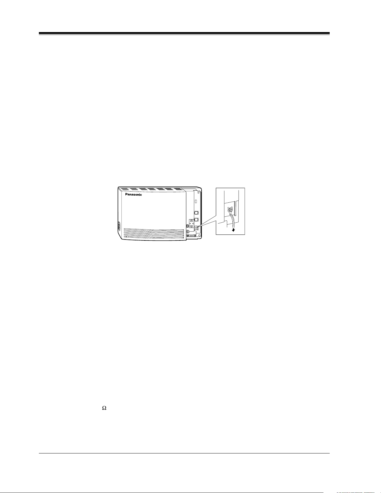
2.7.2 Connecting the RS-232C Cable
RECOMMENDED:
Before connecting the cable, switch off the power on both the data terminal and the VPS.
V
O
I
C
E
P
R
O
C
E
S
S
I
N
G
S
Y
S
T
E
M
P
O
W
E
R
Insert the RS-232C cable into the VPS with the connector indicating the same direction.
The cable must be shielded and no longer than 2 m {6.5 feet}.
36 Installation Manual
Page 37

INSTALLATION
VPS (9 pin)
Circuit
type
(EIA)
BB
BA
CD
AB
CC
VPS (9 pin)
Circuit
type
(EIA)
Signal
name
RXD
TXD
DTR
SG
DSR
Signal
name
Pin
no.
2
3
4
5
6
Pin
no.
9-pin Cable Printer/IBM®-PC
name
RXD
TXD
DTR
SG
DSR
RTS
CTS
Circuit
type
(EIA)
BB
BA
CD
AB
CC
CA
CB
Pin
no.
2
3
4
5
6
7
8
Signal
25-pin Cable Printer/PC
name
Circuit
type
(EIA)
Pin
no.
Signal
BB
BA
CD
AB
CC
RXD
TXD
DTR
SG
DSR
Pin
Number
1
2
3
4
2
3
4
5
6
1
3FGRXDAABB
2
TXD BA
20
DTR
7
SG
5
CTS
6
DSR
8
DCD
CD
AB
CB
CC
CF
Table 7 Pin Configuration of the RS-232C
Circuit Type
Signal Name
RS-232C CCITT
FG
TXD
RXD
RTS
Frame Ground
Transmitted Data
Received Data
Request To Send
AA
BA
BB
CA
101
103
104
105
Installation Manual 37
Page 38

INSTALLATION
Table 7 Pin Configuration of the RS-232C
Pin
Number
6 DSR Data Set Ready CC 107
7
8
20 DTR Data Terminal Ready CD 108.2
SG
DCD
Signal Ground
Data Carrier Detect
2.7.3 RS-232C Signals
Frame Ground (FG)
Connects an external ground to the unit frame, usually the ground pin of the AC power cord.
Transmitted Data (TXD)—output
Conveys signals from the unit to the terminal/printer. A "mark" condition is held unless data
or BREAK signals are being transmitted.
Received Data (RXD)—input
Conveys signals from the terminal/printer to the unit.
Signal Name
Circuit Type
RS-232C CCITT
AB
CF
102
109
Request To Send (RTS)—output
This lead is held on whenever DSR is on.
Signal Ground (SG)
Connects to the DC ground of the unit for all interface signals.
Data Terminal Ready (DTR)—output
This signal line is turned on by the unit to indicate that it is RS-232C on-line. Circuit DTR ON
does not indicate that communication has been established with the terminal/printer. It is
switched off when the unit is RS-232C off-line.
38 Installation Manual
Page 39

INTEGRATING THE VPS WITH PANASONIC KX-T PHONE SYSTEMS
Section 3
INTEGRATING THE VPS WITH
PANASONIC KX-T PHONE SYSTEMS
Installation Manual 39
Page 40

INTEGRATING THE VPS WITH PANASONIC KX-T PHONE SYSTEMS
3.1 GUIDELINES FOR INTEGRATION
3.1.1 APT/DPT or Inband Signaling?
There are 3 types of integration available on the VPS: Inband Signaling, APT and DPT. The
VPS used with any other brand of telephone equipment requires inband equipment.
KX-TA624 that can use APT Integration is:
• KX-TA624 Version Y581A or higher.
KX-TD series PBXs that can use DPT Integration are:
• KX-TD308 Version P871F or higher
• KX-TD816 Version P301O or higher
• KX-TD1232 Version P231U or higher
• KX-TD500 Version Q171A or higher
Likewise, the KX-TA1232 can also use DPT Integration:
• KX-TA1232 Version P831AA or higher (all versions)
Notes
• To the VPS, the KX-TA1232 looks identical to the KX-TD1232.
• Depending on the model and/or the software version of the connected PBX, you may
not be able to utilize some of the features available only with DPT Integration (see
4.1.1 Why Digital Integration is Important). For more information, call National
Parts Center at 1-800-833-9626.
3.1.2 Why Integration is Important
The VPS works well with most PBXs because its connections are made through a standard
single-line (tip/ring) telephone interface. However, the VPS operation depends on the
capabilities and features provided by the PBX; its performance will vary when connected with
different PBX systems. For example, Follow-on (or Called Party) ID is a feature of the PBX.
If the PBX does not have this feature, the VPS cannot transfer calls directly to the correct
mailbox and play the Busy or No Answer greeting for that mailbox.
3.1.3 How the VPS and the PBX Communicate
To the PBX, the VPS looks like SLT sets. The PBX thinks that the VPS is an SLT, and the VPS
mimics all actions a live attendant would carry out from an SLT.
For the VPS and the PBX to communicate, proper signaling is important. Like an attendant,
the VPS places calls by going off-hook and dialing numbers. It starts call transfers with a
hookswitch flash to put callers on hold and then dials the extension number. By recognizing
call progress tones from the PBX, the VPS decides how calls should be handled. Inband
40 Installation Manual
Page 41

INTEGRATING THE VPS WITH PANASONIC KX-T PHONE SYSTEMS
Integration allows the PBX to send certain digits (touchtone) to the VPS, allowing it to
recognize the status of the extension and take the appropriate action.
Table 8
VPS/PBX COMMUNICATION
PBX to VPS
Call Progress Tones
• ringback
• busy
• reorder
Touchtones
The VPS must also have access to certain PBX features. For example, if the VPS takes a
message, one way it can notify the mailbox owner is by dialing the PBX's Message-WaitingLamp-On code. Once new messages are retrieved, the VPS dials the Message-Waiting-LampOff code for that same mailbox owner.
VPS to PBX
SLT Signals
• on/off hook
• hookswitch flash
• touchtones
3.1.4 PBX Requirements for Integration
The PBX must have certain capabilities and features to work with the VPS. (Although this
section includes tests to help you evaluate the PBX, it may be necessary to refer to the PBX's
documentation for detailed capability and feature descriptions.)
Single Line (Tip/Ring) Port Circuits
The VPS can only be connected to a PBX that supports SLT sets. Some PBXs need an OPX
card to provide this connection. However, some OPX cards do not provide all the capabilities
listed in this section.
Following are the minimum current and voltages that the PBX must supply:
Table 9
Minimum Loop Current 20 mA
Minimum Line Voltage 7 V DC
Minimum Ringing Voltage 40 V AC
Station to Station Touchtone Signaling
For system users to access VPS services and features, they must be able to send touchtones
from their telephones to the VPS port. As a general rule, SLT sets can perform station-tostation touchtone signaling; however, many proprietary telephones cannot. Some PBXs need
to be programmed to make proprietary sets use touchtone signaling.
Installation Manual 41
Page 42

INTEGRATING THE VPS WITH PANASONIC KX-T PHONE SYSTEMS
If the PBX does not provide station-to-station touchtone signaling, VPS services and
features will be limited.
TEST:Call an SLT extension from the telephone in question. When the call
is answered, see if the person receiving the call hears touchtones when
numbers are dialed.
Message Waiting Notification from an SLT
The PBX extensions should light a lamp or receive stutter dial tone when the MessageWaiting-Lamp-On code is dialed by the VPS. The VPS functions best when the extension
number of the voice mailbox owner follows the Light-On or Light-Off code. On some PBXs,
however, the extension number is dialed first, followed by a hookswitch flash and then the On
code. This presents a problem if the extension is answered before the VPS sends the hookswitch flash.
If the PBX does not provide message waiting notification from an SLT, the VPS can only
notify mailbox owners by dialing a beeper number or user-assigned extension.
This process slows down VPS performance as it dials the beeper or extension number and
waits to confirm notification. The beeper or user-assigned extension notification is meant to be
used for necessity, usually for mailbox owners who are often out of the office (e.g., sales
people or field representatives). The only other option, without message waiting notification,
is for mailbox owners to periodically call the VPS to check for messages.
TEST: See if dialing the On code from an SLT can turn on an extension's
message waiting indicator.
Screened Transfer from an SLT
The PBX must provide a screened transfer from an SLT for the VPS to function properly.
A screened transfer:
Puts the caller on hold, usually with a hookswitch flash.
1.
Dials the extension.
2.
Checks to see if the called subscriber is in, out, or on another line, and whether or not that
3.
subscriber accepts the transfer.
Completes the transfer (by going on-hook) or returns to the caller to say that the party is
4.
busy or not available. It then gives the caller an opportunity to leave a message.
42 Installation Manual
Page 43

If the PBX does not provide screened transfer from an SLT, the VPS cannot give callers the
option to leave a message in a subscriber's mailbox.
TEST: Place an outside call from an SLT. See if you can set up a screened
transfer to another extension. Next, try the same test with an internal call.
(The VPS may have to transfer both types of calls.)
Follow-on ID or Called Party ID
When forwarding or transferring a call to the VPS, a PBX with Follow-on ID sends the mailbox
number of the called subscriber to the VPS before connecting the caller. The VPS responds by
playing that subscriber's personal greeting. This operation is sometimes called Call Forward to
Mailbox. Without this feature, the VPS cannot immediately play the greeting when the line is
busy or there is no answer and allow the caller to leave a message.
INTEGRATING THE VPS WITH PANASONIC KX-T PHONE SYSTEMS
Installation Manual 43
Page 44

INTEGRATING THE VPS WITH PANASONIC KX-T PHONE SYSTEMS
3.2 PBX PARAMETERS AND PORT SETTINGS
3.2.1 General Guidelines and Definitions
Optimal performance of the VPS/PBX system relies on proper VPS programming. There are
3 categories of hardware settings: RS-232C, Port Settings, and PBX Interface Parameters.
Entering a number sets some of the parameters, while others use sequence codes.
3.2.2 RS-232C Settings
• Baud Rate (300-38400): Specifies the speed at which the data is transferred in bits-per-
second.
• Word Bit Length (7-8): Defines the number of bits in each byte or character.
• Parity (N, O, E): Specifies the parity used for error detection.
• Stop Bit Length (1-2): Specifies the number of bits used to signify the end of the byte.
• Default: 9600, 8, N, 1
3.2.3 Port Settings
There is no need to change these in a typical installation. Only change these parameters when
connecting the VPS to a PBX other than a KX-T series PBX. Each port on the VPS should
match the type of signaling the PBX expects. If you need to change these settings, refer to the
PBX manual or customer support office to get the correct values for these settings.
• Flash Time—100 ms, 300 ms, 600 ms, 900 ms:
The minimum length of time that the PBX requires to recognize a hookswitch flash.
Choose the amount that is equal to or greater than the PBX's setting.
• CPC Signal (Calling Party Control Signal)—NONE, 6.5 ms, 150 ms, 300 ms, 450 ms,
600 ms:
The length of time allowed for the short break in loop current that is used to indicate
that the caller has hung up; usually set to NONE, since most PBXs do not provide this
signal to single line ports. If choosing a setting other than NONE, use an amount equal
to or less than the PBX or telephone company provided CPC signal.
• Disconnect Time—1 s-8 s:
The length of time that the line is temporarily unavailable after a call has ended.
• Dial Mode—Touchtone, Pulse 10 pps, Pulse 20 pps:
The type of signaling the PBX single line port expects to receive (pps = pulses per
second).
44 Installation Manual
Page 45

INTEGRATING THE VPS WITH PANASONIC KX-T PHONE SYSTEMS
3.2.4 PBX Interface Parameters
Dialing Parameters
• PBX Type:
Specifies the type of PBX which is connected to the VPS.
• Integration Mode:
Specifies the method of integration to be used between the VPS and PBX. If PBX type is set
to the Panasonic KX-T series, the Inband Signaling parameters are set automatically and
should not be altered. APT Integration is only available when a KX-TA624 PBX is
connected and the software is upgraded. DPT Integration is only available when a KX-TD
series or KX-TA1232 PBX is connected and the software is upgraded.
Table 10
SEQUENCE CODES
D Disconnect
F Hookswitch Flash
R Ring Detection
S Silence Detection
T Dial Tone Detection
W Wait for 1 Second
X Dial Extension
A: Answer
0-9, , #
• Operator Transfer Sequence:
Tells the VPS how to transfer a call to the operator.
Example: FTX [hookswitch flash—dial tone—dial (operator) extn.]
• Extension Transfer Sequence:
Tells the VPS how to transfer a call to an extension.
Example: FTX [hookswitch flash—dial tone—dial extn.]
• Alternate Extension (Transfer Sequence):
Tells the VPS how to transfer a call to an extension that belongs to the "Alternate Extension
Group". This is useful for extensions that need a special transfer procedure (i.e., blind
transfer) such as modem extensions.
Example: FTXD [hookswitch flash—dial tone—dial extn.—hang up]
• Reconnect Sequence on Busy:
Tells the VPS how to return to the caller if the called extension is busy. PBXs differ in how
they handle this function. Test from an SLT to determine the sequence.
Touchtone Digits
Installation Manual 45
Page 46

INTEGRATING THE VPS WITH PANASONIC KX-T PHONE SYSTEMS
• Reconnect Sequence on No Answer:
Tells the VPS how to return to the caller if the called extension does not answer. PBXs differ
in how they handle this function. Test from an SLT to determine the sequence.
• Reconnect Sequence on Refused Call:
Tells the VPS how to return to the caller if the called extension's owner has enabled Call
Screening to not take the call. PBXs differ in how they handle this function. Test from an
SLT to determine the sequence.
• Light On Sequence for Message Waiting Lamp:
This is the dialing sequence that the VPS must use to turn on a message waiting lamp at an
extension.
• Light Off Sequence for Message Waiting Lamp:
This is the dialing sequence that the VPS must use to turn off a message waiting lamp at an
extension.
• Call Waiting Sequence:
This sequence is carried out by the VPS to perform call waiting when the called extension
is busy. PBXs differ in how they handle this function. Test from an SLT to determine the
sequence.
• Release Sequence for Call Waiting:
This sequence is carried out by the VPS to release call waiting. PBXs differ in how they
handle this function. Test from an SLT to determine the sequence.
Inband Signaling
These parameters are used when the Integration Mode is set to Inband. If the PBX type is set
to a KX-T series system, these parameters will be automatically set. If another type PBX is
used, check that system's installation manual for settings.
Code
(default)
1 Ringback Tone The extension dialed is ringing.
2 Busy Tone The extension dialed is busy.
3
4 DND The extension dialed has set DND feature (Do Not Disturb).
5 Answer The extension dialed is answered.
6
Table 11
Call State Sent to the Voice Mail Port When...
Reorder Tone An invalid extension number is dialed or the call is
inadvertently connected to another Voice Mail port (also
heard when no touchtone receiver is available to the Voice
Mail extension).
Forwarded to
Voice Mail
(Ringing)
The extension dialed is forwarded to Voice Mail and
another Voice Mail port is able to answer. (This lets the first
Voice Mail port, usually an Auto Attendant, send the call to
the other Voice Mail port.)
46 Installation Manual
Page 47

INTEGRATING THE VPS WITH PANASONIC KX-T PHONE SYSTEMS
Table 11
Code
(default)
7
8
9
#9
Call State Sent to the Voice Mail Port When...
Forwarded to
Voice Mail (Busy)
Forwarded to Extn. The extension dialed is forwarded to another non-Voice
Confirmation Tone The Message Waiting Lamp On or Message Waiting Lamp
Disconnect The caller disconnects. The central office must set a CPC
Digit Translation Table Parameters
These parameters allow PBXs that have a fixed Follow-on ID sequence to be used with the
VPS. For example, a Follow-on ID sequence of [ 1001] can be changed to [#61001] by
using these parameters.
• Inter-Digit Time-Out: This parameter defines the interval of incoming signals (Follow-
on ID) from the PBX to the VPS. The Digit Translation Table applies the digits received
within this time to translation.
• Input-Output (up to 8 alphanumeric characters): When the system receives digits
within the inter-digit time, it checks them against the input table. If they are found, the
system utilizes the output digits in their place.
The extension dialed is forwarded to Voice Mail and no
other Voice Mail ports are available to accept the call. (This
signals the Voice Mail port [usually Auto-Attendant] to let
the caller to leave a message.)
Mail extension.
Off code is dialed successfully.
signal to the PBX line for this signal to work for outside
calls.
The remainder of this section consists of step-by-step guides for software verification
and programming of the recommended Panasonic PBX systems.
If you (the dealer) have any problem as you go through this section, please call
1-800-211-PANA(7262).
Installation Manual 47
Page 48

INTEGRATING THE VPS WITH PANASONIC KX-T PHONE SYSTEMS
3.3 CONNECTING THE VPS WITH PANASONIC
KX-T SERIES PBXs
3.3.1 VPS Programming for Inband Integration
Set parameters from the System Administration Terminal. The table below lists recommended
parameters for Panasonic KX-T series PBXs.
Table 12
PBX Type Other
Manufac-
Integration
Mode
Operator
Transfer
Sequence
Extension
Transfer
Sequence
Alternate
Extension
Transfer
Sequence
Reconnect
Sequence on
Busy
Reconnect
Sequence on No
Answer
T308/
T616
turers
None None None None None None None None None
Inband Inband Inband Inband Inband Inband Inband Inband
FX (A) FTX
(A)
FX (A) FTX
(A)
FX (A) FTX
(A)
FWW FWW FWW FWW FWW FWW FWW FWW FWW
FWW FWW FWW FWW FWW FWW FWW FWW FWW
T1232 T96 T336 TD816/
TD1232/
TA1232
FTX
(A)
FTX
(A)
FTX
(A)
FTX
(A)
FTX
(A)
FTX
(A)
FTX
(A)
FTX
(A)
FTX
(A)
FTX (A) FTX
FTX (A) FTX
FTX (A) FTX
TD308 TA
series
FTX (A) FTX
(A)
FTX (A) FTX
(A)
FTX (A) FTX
(A)
TD500
(A)
(A)
(A)
Reconnect
Sequence on
Refuse Call
Light-On
Sequence for
Message
Waiting Lamp
Light-Off
Sequence for
Message
Waiting Lamp
FWW FWW FWW FWW FWW FWW FWW FWW FWW
* N/A T701X# T#91X
* N/A T702X# T#90X T#9X T700X T700X T702X# T700X
T9X
T701X T701X T701X# T701X
48 Installation Manual
Page 49

INTEGRATING THE VPS WITH PANASONIC KX-T PHONE SYSTEMS
Table 12
PBX Type Other
Manufac-
turers
Call Waiting
Sequence
Release
Sequence for
Call Waiting
* Check with manufacturer.
N/A Not Available
(A) Adding "A" for "answer" to the operator and extension transfer eliminates the message:
"You have a call" when the AA transfers a call. The VPS disconnects after line is
answered. Adding "D" for "disconnect" creates a blind transfer.
*N/A1N/AN/A1111
*N/AFN/AN/AFFFF
T308/
T616
T1232 T96 T336 TD816/
TD1232/
TA1232
TD308 TA
series
TD500
3.3.2 KX-T123211D Software Verification and Programming for
Inband Integration
1. Check the software version of the KX-T123211D by using System Program [98], which
shows the software version number:Y201Z940430
The underlined digits represent the software production date code (format YYMMDD). In
this example, the date code is April 30, 1994 (year, month, day). For this software version,
the software production date of the PBX must be April 30, 1994, or later.
If the software production date of the PBX is earlier than 4/30/94, call National Parts
Center (1-800-833-9626) to order a software upgrade.
(TM3)
2. Enable System Program [80] for each extension connected to the VPS.
This parameter is used to tell the KX-T123211D which extensions are connected to the
VPS. Ports with this parameter enabled can receive Follow-on ID and DTMF call status
signaling (busy, answered, disconnect, etc.) if the Voice Mail integration and DTMF
integration features are also enabled.
3. Enable System Program [81] to turn on DTMF Integration. On extensions with the Voice
Mail port parameter enabled, the KX-T123211D can send codes (touchtones) to indicate
call states; this increases VPS efficiency. Codes apply to all transferred calls; outside calls
only indicate disconnect (provided the KX-T123211D is programmed for CPC detection
and the Central Office sends the CPC signal). Refer to the Table 10 in the Section
3.2.4 PBX Interface Parameters.
Installation Manual 49
Page 50

INTEGRATING THE VPS WITH PANASONIC KX-T PHONE SYSTEMS
4. Put all extensions connected to the VPS into 1 extension group using System Program [60].
Reserve this extension group for these extensions! Do not mix other extensions into this
group.
5. Enable hunting for the VPS extension group using System Program [08].
6. Set the hunting type for the VPS extension group to circular using System Program [09].
7. At every VPS extension, temporarily connect an SLT or butt set, go off-hook and dial
7301# to turn on Data Line Security. This prevents the KX-T123211D from sending
Executive Override or Call Waiting tones to these extensions. We recommend that all
Voice Mail port extensions have this feature enabled to avoid interruption of recording.
8. At every user’s extension, go off-hook and dial 7192#. This sets the proper Follow-on ID
sequences so that forwarded calls go directly to the extension’s mailbox. The KXT123211D automatically sends the extension’s digits to the Voice Mail port before
connecting the caller.
For Follow-on ID to work:
• Ports connected to the VPS must be assigned as Voice Mail ports.
• Extensions must be forwarded to the first port of the Voice Mail (using the Busy/No
Answer mode or the All Calls mode).
• The mailbox number should be the same as the extension number.
Interaction with other features:
• Call Forwarding—If the extension is forwarded to an extension that is also
forwarded, the forwarding will not work.
• Call Hunting—Hunting does not interfere with Follow-on ID.
• Call Transfer—Calls transferred to an extension with Follow-on ID and call
forwarding enabled will be forwarded directly to the mailbox.
• Data Line Security—We recommend that all Voice Mail port extensions have this
feature enabled to avoid interruption of recording by Executive Override tone or
Call Waiting tone.
9. Select the appropriate outside (CO) Line feature settings depending on how your customer
plans to use the VPS: A) to answer all incoming calls, B) as an operator backup, or C) to
only answer calls not answered by user extensions.
Recommended outside (CO) line feature settings:
a) If the VPS is answering all incoming calls:
Outside (CO) Line Mode—Use System Programs [51] and [52] to set this
parameter. Program all lines DIL to the first extension of the Voice Mail hunt group.
The KX-T123211D will allow incoming CO calls to hunt only if the outside (CO)
lines are DIL to the first port of the hunt group. Lines programed as "Normal" do not
hunt.
50 Installation Manual
Page 51

INTEGRATING THE VPS WITH PANASONIC KX-T PHONE SYSTEMS
b) If the VPS is only answering calls not answered by the operator (Operator Backup):
Flexible Ringing Assignment—For each outside (CO) line, use System Programs
[47] (Day Mode) and [48] (Night Mode) to enable ringing at the operator’s extension
(jack).
Delayed Ringing Assignment—To give the operator time to answer the call before
the VPS picks up, we recommend setting the delay to 3 or 4 rings for each extension
connected to the VPS. Use System Programs [49] (Day Mode) and [50] (Night
Mode).
Outside (CO) Line Mode—Set the mode for each outside (CO) line to "Normal".
Use System Programs [51] and [52] to set this parameter.
c) If the VPS is only answering calls not answered by user extensions:
Flexible Ringing Assignment—For each outside (CO) line, use System Programs
[47] (Day Mode) and [48] (Night Mode) to enable ringing on every extension (jack)
that you want to have ring.
Delayed Ringing Assignment—To give users time to answer the call before the
VPS picks up, we recommend setting the delay to 3 or 4 rings for each extension
connected to the VPS. Use System Programs [49] (Day Mode) and [50] (Night
Mode).
CO Mode—Set the mode for each outside (CO) line to "Normal". Use System
Programs [51] and [52] to set this parameter.
3.3.3 KX-TA Series Programming for Inband Integration via the
Manager’s Extension
Note
If your PBX is the KX-TA1232, please refer to the procedure described in 3.3.5 KX-
TD816, KX-TD1232, KX-TA1232 and KX-TD308 Programming for Inband Integration via
the Manager’s Extension or 3.3.6 KX-TD816, KX-TD1232, and KX-TA1232 Programming
for Inband Integration via the Operating and Maintenance Tool for programming.
1. Enable System Program [102] for each extension connected to the VPS. Jack 07, or jacks
07 and 08 can be assigned for the VPS1 as the Voice Mail port. Jack 15, or jacks 15 and 16
can be assigned for the VPS2.
This parameter is used to tell the KX-TA series which extensions are connected to the VPS.
Ports with this parameter enabled can receive Follow-on ID and touchtone call status
Signaling (busy, answered, disconnect, etc.) if the Voice Mail integration and Touchtone
Integration features are also enabled.
2. Enable System Program [103] to turn on Touchtone Integration. On extensions with the
Voice Mail port parameter enabled, the KX-TA series can send codes (touchtones) to
indicate call states; this increases VPS efficiency. Codes apply to all transferred calls;
outside calls only indicate disconnect (provided the KX-TA series is programmed for CPC
Detection, and the Central Office sends the CPC signal). Refer to the Table 10 in Section
3.2.4 PBX Interface Parameters.
Installation Manual 51
Page 52

INTEGRATING THE VPS WITH PANASONIC KX-T PHONE SYSTEMS
3. Put all extensions connected to the VPS into 1 extension group using System Program
[600].
Reserve this extension group for these extensions! Do not mix other extensions into this
group.
Note
Up to two VPS units can be connected to the KX-TA624. When two VPS units are
connected to the KX-TA624, 2 different extension groups should be assigned for each
VPS in System Program [600]. One extension group is for jack 07, or jacks 07 and 08 of
the KX-TA624. The other extension group is for jack 15, or jacks 15 and 16.
4. Enable hunting for the VPS extension groups using System Program [100].
5. Set the hunting type for the VPS extension groups to circular using System Program [101].
6. At every VPS extension, temporarily connect an SLT or butt set, go off-hook and dial
7301# to turn on Data Line Security. This prevents the KX-TA series from sending
Executive Override or Call Waiting tones to these extensions. We recommend that all
Voice Mail port extensions have this feature enabled to avoid interruption of recording.
7. Select the appropriate outside (CO) line feature settings depending on how your customer
plans to use the VPS: A) to answer all incoming calls, B) as an operator backup, or C) to
only answer calls not answered by user extensions.
Recommended outside (CO) line feature settings:
a) If the VPS is answering all incoming calls:
Outside (CO) Line Mode—Use System Programs [414] (Day Mode), [415] (Night
Mode), [416] (Lunch Mode) to set this parameter. Program all lines DIL to the first
extension of the Voice Mail hunt group. The KX-TA series will allow incoming
outside calls to hunt only if the outside (CO) lines are DIL to the first port of the hunt
group. Lines programmed as "Normal" do not hunt.
b) If the VPS is only answering calls not answered by the operator (Operator Backup):
Flexible Ringing Assignment—For each outside (CO) line, use System Programs
[408] (Day Mode), [409] (Night Mode) and [410] (Lunch Mode) to enable ringing at
the operator’s extension (jack).
Delayed Ringing Assignment—To give the operator time to answer the call before
the VPS picks up, we recommend setting the delay to a few seconds for each
extension connected to the VPS. Use System Programs [411] (Day Mode), [412]
(Night Mode) and [413] (Lunch Mode).
Outside (CO) Line Mode—Set the mode for each outside (CO) line to "Normal".
Use System Programs [414] (Day Mode), [415] (Night Mode) and [416] (Lunch
Mode) to set this parameter.
c) If the VPS is only answering calls not answered by user extensions:
52 Installation Manual
Page 53

INTEGRATING THE VPS WITH PANASONIC KX-T PHONE SYSTEMS
Flexible Ringing Assignment—For each outside (CO) line, use System Programs
[408] (Day Mode), [409] (Night Mode) and [410] (Lunch Mode) to enable ringing
on every extension (jack) that you want to have ring.
Delayed Ringing Assignment—To give users time to answer the call before the
VPS picks up, we recommend setting the delay to a few seconds for each extension
connected to the VPS. Use System Programs [411] (Day Mode), [412] (Night Mode)
and [413] (Lunch Mode).
Outside (CO) Line Mode—Set the mode for each outside (CO) line to "Normal".
Use System Programs [414] (Day Mode), [415] (Night Mode) and [416] (Lunch
Mode) to set this parameter.
CAUTION
DO NOT create a mailbox in both VPS for the same extension. Each extension can have a
maximum of 1 mailbox in either VPS. The extension should assign a Voice Mail extension
from the VPS which contains its mailbox as the destination for Call Forwarding and Voice
Mail Transfer. DO NOT assign a Voice Mail extension from the other VPS. For example, if
jack 06 (extension 106) has its mailbox in the VPS1, assign extension 107 or 108 as the
destination, not extension 115 or 116 (see the following diagram).
KX-TA series
6
7
8
Group A
15
16
Group B
Extension 106
VPS1
Port 1
Extension 107
Port 2
Extension 108
Mailbox for Extension 106
VPS2
Port 1
Extension 115
Port 2
Extension 116
Installation Manual 53
Page 54

INTEGRATING THE VPS WITH PANASONIC KX-T PHONE SYSTEMS
3.3.4 KX-TD500 Programming for Inband Integration
Whenever possible, we recommend that you use DPT Integration. However, in some cases,
this is not possible. In the following situations, you need to use Inband Integration:
• Your PBX is a third-party telephone system.
• You have a KX-TD500, but all the extension cards are analog types.
• You have a KX-TD500, but the DHLC/DLC cards are ancient versions (therefore,
cannot support DPT Integration).
1. Assignment of the extension card to be connected to the VPS
a)
Go to the "1-1 Slot Assignment" screen.
b)
Assign the slot card type to be installed to "DHLC", "HLC", "SLC", "ESLC", or
"SLC-M" SLT interface supports.
c)
Click "Apply" to save the slot card type assignment.
d)
Set "Card Status" to "INS".
Screen output:
54 Installation Manual
Page 55

INTEGRATING THE VPS WITH PANASONIC KX-T PHONE SYSTEMS
2. Assignment of the extension ports to be connected to the VPS
a)
Go to the "1-3 Extension Port Assignment" screen.
b)
Assign "Attribute" of the port to be connected to "TEL" (default).
c)
Assign "DN" for the port (click "DN Refer" to check the available directory numbers).
Note:
This program allows you to assign an extension number to each Voice Mail port.
To reach the Voice Mail system, users dial these extension numbers.
d)
Assign "Extension Group No." for the port.
Note:
Specify the extension group number (126 or 127 by default) to which VM or AA
extension groups have been assigned. Group numbers 1 to 128 are available to the
VPS through additional programming.
e)
Click "Apply" to save the changed data.
f)
Set "Port Status" to "INS".
Screen output:
Installation Manual 55
Page 56

INTEGRATING THE VPS WITH PANASONIC KX-T PHONE SYSTEMS
3. Assignment of the extension line to be connected to the VPS
a)
Go to the "4-2 Extension Line" screen.
b)
Set "Data Line Mode" to "Yes".
c)
Click "Apply" to save the changed data.
Note:
This program prevents the VM port from being interrupted by "Call Waiting",
"Hold Recall", and "Executive Busy Override" features during a call.
Screen output:
56 Installation Manual
Page 57

INTEGRATING THE VPS WITH PANASONIC KX-T PHONE SYSTEMS
4. Settings for the trunk (CO line) features
Select the appropriate trunk (CO line) feature settings depending on how your
customer plans to use the VPS.
• The VPS answers all incoming outside calls promptly.
Go to [Recommended Settings (1)].
• The VPS answers when the operator does not take the call after a specified number of
rings.
Go to [Recommended Settings (2)].
• The VPS answers when an extension user does not take the call after a specified
number of rings.
Go to [Recommended Settings (3)].
[Recommended Settings (1)]
If the VPS is answering all incoming outside calls:
a) Assignment of DIL 1:1 line
1)
Go to the "4-1 Trunk Line" screen.
2)
Assign "Destination Day/Night/Lunch/Break" for each trunk (CO line) to a
specific extension number (VPS port).
3)
Click "Apply" to save the changed data.
Note:
Specify the FDN for the extension group to which VM or AA has been assigned.
In order to utilize the Caller ID features, you must Set "Caller ID" to "Enable".
Screen output:
Installation Manual 57
Page 58

INTEGRATING THE VPS WITH PANASONIC KX-T PHONE SYSTEMS
[Recommended Settings (2)]
If the VPS is only answering incoming outside calls not answered by the Operator (Operator
backup):
a) Assignment of DIL 1:1 line
1)
Go to the "4-1 Trunk Line" screen.
2)
Assign "Destination Day/Night/Lunch/Break" for each trunk (CO line) to a
specific extension number.
3)
Click "Apply" to save the changed data.
Note:
Specify the FDN for the extension group to which Operator has been assigned.
Screen output:
58 Installation Manual
Page 59

INTEGRATING THE VPS WITH PANASONIC KX-T PHONE SYSTEMS
b) Assignment of IRNA (Intercept Routing No Answer) destination:
1)
Go to the "3-1 Trunk Group" screen.
2)
Assign "Intercept Destination Day/Night" for the trunk (CO line) group.
3)
Click "Apply" to save the changed data.
Note:
Specify the FDN for the extension group to which VM or AA has been assigned.
Screen output:
Installation Manual 59
Page 60

INTEGRATING THE VPS WITH PANASONIC KX-T PHONE SYSTEMS
c) Assignment of IRNA (Intercept Routing No Answer) timer:
1)
Go to the "2-4 System Timer 1/2" screen.
2)
Assign "Intercept Time" parameter.
3)
Click "Apply" to save the changed data.
Note:
This parameter tells the KX-TD500 how long to let a call ring at an extension
before forwarding (redirecting).
Screen output:
60 Installation Manual
Page 61

INTEGRATING THE VPS WITH PANASONIC KX-T PHONE SYSTEMS
[Recommended Settings (3)]
If the VPS is only answering incoming outside calls not answered by user extensions:
a) Assignment of DIL 1:1 line
1)
Go to the "4-1 Trunk Line" screen.
2)
Assign "Destination Day/Night/Lunch/Break" for each trunk (CO line) to a
specific extension number.
3)
Click "Apply" to save the changed data.
Screen output:
Installation Manual 61
Page 62

INTEGRATING THE VPS WITH PANASONIC KX-T PHONE SYSTEMS
b) Assignment of IRNA (Intercept Routing No Answer) destination:
1)
Go to the "3-1 Trunk Group" screen.
2)
Assign "Intercept Destination Day/Night" for the trunk (CO line) group.
3)
Click "Apply" to save the changed data.
Note:
Specify the FDN for the extension group to which VM or AA has been assigned.
Screen output:
62 Installation Manual
Page 63

INTEGRATING THE VPS WITH PANASONIC KX-T PHONE SYSTEMS
c) Assignment of IRNA (Intercept Routing No Answer) timer:
1)
Go to the "2-4 System Timer 1/2" screen.
2)
Assign "Intercept Time" parameter.
3)
Click "Apply" to save the changed data.
Note:
This parameter tells the KX-TD500 how long to let a call ring at an extension
before forwarding (redirecting).
Screen output:
3.3.5 KX-TD816, KX-TD1232, KX-TA1232 and KX-TD308
Programming for Inband Integration via the Manager’s
Extension
Select a maximum of 2 station ports to be connected to the VPS. Plug each station into a Voice
Mail port.
Go into System Program [602] and assign the Voice Mail stations to a different extension
group. By default, all stations are in Extension Group 1.
Go into System Program [106] and assign the new Extension Group to Auto Attendant (AA).
Installation Manual 63
Page 64

INTEGRATING THE VPS WITH PANASONIC KX-T PHONE SYSTEMS
3.3.6 KX-TD816, KX-TD1232, and KX-TA1232 Programming for
Inband Integration via the Operating and Maintenance Tool
1.
Go to the Main Menu. Choose "System Data Programming".
(BATCH [1] or INTERACTIVE [2]).
• Before choosing Batch Programming, you must open a file in the Disk File
Management Menu (Item 3).
• Before choosing Interactive Programming, you must connect with the system in the
DSHS Connect/Disconnect menu.
Main Menu
1. System Data Programming (BATCH)
2. System Data Programming (INTERACTIVE)
3. Disk File Management
4. DSHS Management
5. DSHS Connect/Disconnect
6. Quit
Select the number : [ ]
2.
Choose "Station" from the System Data Programming Main Menu.
System Data Programming Main Menu
1. Line
2. Station
3. System
4. Toll Restriction
5. ARS
6. Aux. Ports
7. Additional Function
8. Caller ID
Select the number: [2]
3.
Choose "Station Setting" from the Station Menu.
Station Menu
1. Station Setting
2. COS & Mailbox ID
3. CO line Outgoing
4. DIL 1:N
5. ISDN Extension Setting
6. SDN Extension CO outgoing
7. Flexible CO Keys
8. Flexible PF Keys
9. DSS
10. Lunch/Break Group
11. FWD/DND Setting
12. FWD/DND Setting (OPX)
Select the number: [1]
64 Installation Manual
Page 65

INTEGRATING THE VPS WITH PANASONIC KX-T PHONE SYSTEMS
4.
Enable XDP ports. Place Voice Mail extensions in Extension Group 8.
Station Setting
Jack EXT Name X E Doorphone LCS
D X Day Night Mode
P G 1 2 3 4 1 2 3 4
01-1 [ 101 ] [ ] N
01-2 [ 201 ] [ ] -
02-1 [ 102 ] [ ] N
02-2 [ 202 ] [ ] 03-1 [ 103 ] [ ] N
03-2 [ 203 ] [ ] 04-1 [ 104 ] [ ] N
04-2 [ 204 ] [ ] 05-1 [ 105 ] [ ] Y
05-2 [ 205 ] [ ] 06-1 [ 106 ] [ ] Y
06-2 [ 206 ] [ ] -
07-1 [ 107 ] [ ] N
07-2 [ 207 ] [ ] 08-1 [ 108 ] [ ] N
08-2 [ 208 ] [ ] -
[ 1 ] Y Y Y Y Y Y Y Y Stop Rec
[ 1 ] N N N N N N N N
[ 1 ] N N N N N N N N Stop Rec
[ 1 ] N N N N N N N N
[ 1 ] N N N N N N N N Stop Rec
[ 1 ] N N N N N N N N
[ 1 ] N N N N N N N N Stop Rec
[ 1 ] N N N N N N N N
[ 1 ] N N N N N N N N Stop Rec
[ 8 ] N N N N N N N N
[ 1 ] N N N N N N N N Stop Rec
[ 8 ] N N N N N N N N
[ 1 ] N N N N N N N N Stop Rec
[ 1 ] N N N N N N N N
[ 1 ] N N N N N N N N Stop Rec
[ 1 ] N N N N N N N N
FWD
N/A
Time
[00]
[00]
[00]
[00]
[00]
[00]
[00]
[00]
[00]
[00]
[00]
[00]
[00]
[00]
[00]
[00]
Cordless
PITS
N
–
N
–
N
–
N
–
N
–
N
–
N
–
N
–
5.
Return to the System Data Programming Main Menu. Select "System".
6.
Choose "Miscellaneous" from the System Menu.
System Menu
01. Day/Night
02. Class of Service
03. Emergency/Quick Dial
04. Speed Dial
05. Absent Message
06. Flexible Numbering
07. Account Code
08. Special Carrier
09. Timer
10. Voice Mail
11. Voice Mail Integration
12. UCD
13. Phantom
Select the number: [15]
14. Opera/Manager/EXT Group
15. Miscellaneous
16. Caller ID Modification
17. Switch Type
18. DID
19. Lunch/Break Time
20. System Time
21. Version
22. ISDN Card
23. T1 Card
24. T1 Minor Error
Installation Manual 65
Page 66

INTEGRATING THE VPS WITH PANASONIC KX-T PHONE SYSTEMS
7.
Choose the "Call Hunting" extension group. Set the last extension group to [A] for
Automated Attendant.
Miscellaneous
COT
COT
2
D
EXP2
EXT1
EXT1
Expansion Card Type (Master) =>
(Slave ) =>
Local Access => Priority =
Call Hunting => EXG
SPD TRS Override => HOTEL FEATURE =>
CO Auto-Hold by Push DSS-Key
Adjust Time
PBX Code
8.
Return to the System Data Programming Main Menu. Select "Line" and then select "CO
TRG No. =
No.
=
CO-Key => Off-Hook Monitor
EXP1
1
[1] [2] [3] [4] [5] [6] [7] [8]
12345678
D
Disable Off
=> Enable
Disable
=> [01:00] AM
=> [ ]
EXP3
EXT2
EXT2
3
D
4
D
DID SELECT
5
D
Caller ID Extension
EXP 1 Not Stored
EXP 2 Not Stored
EXP 3 Not Stored
EXP 4 Not Stored
6
D
=>
=>
7
D
EXT Number
Enable
8
A
Line Setting 1". Program all lines DIL to the first extension of the Voice Mail hunt group.
CO Line Setting
CO C T D PD C CPC DIL 1:1
No O R I PT I Detection EXT No
NGA SM D Out NightMode Day
LF
R
E
V
DIL 1:1
Lunch
Group
Break
Grroup
01 Y [1] D 1080 N Disable EXT[205]EXT[205]
02 Y [2] D 1080 N Disable EXT[205]EXT[205]
03 Y [3] D 1080 N Disable EXT[205]EXT[205]
04 Y [4] D 1080 N Disable EXT[205]EXT[205]
05 Y [5] D 1080 N Disable EXT[205]EXT[205]
06 Y [6] D 1080 N Disable EXT[205]EXT[205]
07 Y [7] D 1080 N Disable EXT[205]EXT[205]
08 Y [8] D 1080 N Disable EXT[205]EXT[205]
09 Y [8] D 1080 N Disable EXT[205]EXT[205]
10 Y [8] D 1080 N Disable EXT[205]EXT[205]
11 Y [8] D 1080 N Disable EXT[205]EXT[205]
12 Y [8] D 1080 N
Disable
Disable
Disable
Disable
Disable
Disable
Disable
Disable
Disable
Disable
Disable
Disable EXT[205]
Reg.
Reg.
Reg.
Reg.
Reg.
Reg.
Reg.
Reg.
Reg.
Reg.
Reg.
Reg.Disable
[ ][ ]
[ ][ ]
[ ][ ]
[ ][ ]
[ ][ ]
[ ][ ]
[ ][ ]
[ ][ ]
[ ][ ]
[ ][ ]
[ ][ ]
[ ][ ]EXT[205]
66 Installation Manual
Page 67

INTEGRATING THE VPS WITH PANASONIC KX-T PHONE SYSTEMS
3.3.7 KX-TD308 Programming for Inband Integration via the
Operating and Maintenance Tool
1.
Go to the Main Menu. Choose "System Data Programming".
(BATCH [1] or INTERACTIVE [2])
• Before choosing Batch Programming, you must open a file in the Disk File
Management Menu (Item 3).
• Before choosing Interactive Programming, you must connect with the system in the
DSHS Connect/Disconnect menu.
Main Menu
1. System Date Programming (BATCH)
2. System Date Programming (INTERACTIVE)
3. Disk File Management
4. DSHS Management
5. DSHS Connect/Disconnect
6. Quit
Select menu Number:[ ]
2.
Choose "Station (ALT-S)" from the System Data Programming Main Menu.
System Data Programming Main Menu
AuxPorts (ALT-U)
Manager (ALT-M)
System (ALT-Y)
CO-Line (ALT-L)
Station (ALT-S)
TRS (ALT-T)
ARS (ALT-A)
3.
Choose "Settings (1)" in the Sub Menu.
Sub Menu
Settings (1)
Settings (2)
CO Line (O)utgoing
(D)il Line 1:N
Flex (C)o Keys :1-24
Flex (P) F Buttons :1-12
4.
Choose which single line extensions will be attached to Voice Mail.
1
2
O
D
C
P
If using XDP ports, enable "XDP" for the connect jacks.
Place Voice Mail extensions in Extension Group "8".
Installation Manual 67
Page 68

INTEGRATING THE VPS WITH PANASONIC KX-T PHONE SYSTEMS
Station Setting 1
Jack Ext. Name XDP EXG Day Night LCS Mode
DoorPhone
1-1 [11 ] [ ] [N]
1-2 [21 ] [ ]
2-1 [12 ] [ ] [N]
2-2 [22 ] [ ]
3-1 [13 ] [ ] [N]
3-2 [23 ] [ ]
4-1 [14 ] [ ] [N]
4-2 [24 ] [ ]
5-1 [15 ] [ ] [Y]
5-2 [25 ] [ ]
6-1 [16 ] [ ] [N]
6-2 [26 ] [ ]
7-1 [17 ] [ ] [N]
7-2 [27 ] [ ]
8-1 [18 ] [ ] [N]
8-2 [28 ] [ ]
5.
Select "SAVE(F7)". Return to the System Data Programming Main Menu. Select
[ 1 ] [Y] [Y] [STOP REC]
[ 1 ] [N] [N]
[ 1 ] [N] [N] [STOP REC]
[ 1 ] [N] [N]
[ 1 ] [N] [N] [STOP REC]
[ 1 ] [N] [N]
[ 1 ] [N] [N] [STOP REC]
[ 1 ] [N] [N]
[ 1 ] [N] [N] [STOP REC]
[ 8 ] [N] [N]
[ 1 ] [N] [N] [STOP REC]
[ 1 ] [N] [N]
[ 1 ] [N] [N] [STOP REC]
[ 1 ] [N] [N]
[ 1 ] [N] [N] [STOP REC]
[ 1 ] [N] [N]
"System".
6.
Choose "System (ALT-Y)" from the System Data Programming Main Menu.
System Data Programming Main Menu
Auxports (ALT-U)
Manager (ALT-M)
System (ALT-Y)
CO-Line (ALT-L)
Station (ALT-S)
TRS (ALT-T)
ARS (ALT-A)
68 Installation Manual
Page 69

INTEGRATING THE VPS WITH PANASONIC KX-T PHONE SYSTEMS
7.
Choose "Miscellaneous" from the System Menu.
System Menu
(A)ccount Codes
Caller (I)D
Class of Se(R)vice
(D)ay/Night
(E)mergency/Quick Dial
(F)loating Extensions
Fle(X)ible Numbers
(M)iscellaneous
P(H)antom Extensions
Seria(L) Interface
S(P)ecial Carrier
(T)imers
Add. F(U)nctions - SYSTEM
Add. Functions - (C)OS
(V)M Status/Command DTMF Set
Voice Mail Inte(G)ration
8.
Choose the "Call Hunting" extension group. Set the last extension group to "[AA]" for
A
I
R
D
E
F
X
M
H
L
P
T
U
C
V
G
Automated Attendant.
Miscellaneous
Automatic Access => Priority
Call Hunting => EXG No.
Automatic Hold By CO Button
Automatic Hold By DSS Button
SPD TRS Override
FAX Transfer Extension
Caller ID Extension
Caller ID Modification
Long Distance Call Del,Add
9.
Select "SAVE(F7)". Return to the System Data Programming Menu.
Area Code
Local Call Del,Add
CO No.
=>
1
=>
=>
=> [Disable]
=> [Enable]
=> [Disable]
=> [ ]
=> [ ]
=> [ ]
=> [3 ] [ ]
=> [0 ] [1 ]
23
[1]
[2] [3]
1 2 3 4 5 6 7 8
[DIS] [DIS] [DIS] [DIS] [DIS] [DIS] [DIS] [AA]
Installation Manual 69
Page 70

INTEGRATING THE VPS WITH PANASONIC KX-T PHONE SYSTEMS
10.
Choose "CO-Line (ALT-L)" from the System Data Programming Main Menu.
System Data Programming Main Menu
AuxPorts (ALT-U)
Manager (ALT-M)
System (ALT-Y)
CO-Line (ALT-L)
Station (ALT-S)
TRS(ALT-T)
ARS(ALT-A)
11. Choose "Settings (2)" in the Sub Menu, and program all lines DIL to the first extension
of the Voice Mail hunt group.
Sub Menu
Settings (1) 1
Settings (2) 2
(I)ntercept/Timers/PBX Access Code I
CO Line Setting
CO
1 [400 ms] [Disable]
2 [400 ms] [Disable]
3 [400 ms] [Disable]
CPC CPC
Signal
Detection
Incoming
Detection
Outgoing
Signal
DIL
1:1
EXT NO.
DAY NIGHT
[25 ]
[25 ]
[25 ]
[25 ]
[25 ]
[25 ]
70 Installation Manual
Page 71

INTEGRATING THE VPS WITH THE PANASONIC KX-TA SERIES PBX AND KX-TD SERIES PBX
Section 4
INTEGRATING THE VPS WITH THE
PANASONIC KX-TA SERIES PBX AND KX-
TD SERIES PBX
Installation Manual 71
Page 72

INTEGRATING THE VPS WITH THE PANASONIC KX-TA SERIES PBX AND KX-TD SERIES PBX
4.1 GUIDELINES FOR DIGITAL INTEGRATION
4.1.1 Why Digital Integration is Important
The VPS works well with most PBXs because its connections are made through a standard
single line (tip/ring) telephone interface. However, the communication between the PBX and
VPS is best when Digital Integration is used; the VPS is already set up to communicate through
Digital Integration.
Once Digital Integration is established, the PBX sends information to the VPS through the data
link. This information enables the VPS to identify the extension that is calling, know where
from and why a call is forwarded, and recognize what the caller wants to do. This
communication allows features that are only available with Digital Integration—several of
which are described below:
Table 13
DIGITAL INTEGRATION FEATURES
Remote Call Forwarding Set
(DPT Integration only)
Auto Configuration The VPS knows what extension numbers exist on the
Live Call Screening Extension users can monitor messages as they are
Two-Way Recording Extension users can record conversations into their
Two-Way Transfer Extension users can record conversations into another
Direct Mailbox Access The subscriber can directly enter his mailbox when he
Trunk Service
(Universal Port)
The subscribers and the Message Manager can
program their extensions from a remote location to
forward various types of calls to a desired extension or
an outside telephone.
PBX and creates mailboxes for each extension
automatically. Also sets the VPS clock with data from
the PBX clock.
being left in the mailbox or intercept if required.
own mailboxes by pressing one button.
person’s mailbox by pressing a button and dialing an
extension number.
calls the VPS. He does not have to dial his mailbox
number.
Each PBX trunk (CO line) group can be assigned one
of 4 incoming call services: Voice Mail Service,
Automated Attendant Service, Interview Service and
Custom Service.
72 Installation Manual
Page 73

INTEGRATING THE VPS WITH THE PANASONIC KX-TA SERIES PBX AND KX-TD SERIES PBX
Table 13
DIGITAL INTEGRATION FEATURES
Intercom Paging* Callers can page subscribers through built-in speakers
and external paging equipment. For a Caller ID Caller,
if his name has been recorded for the Caller Name
Announcement feature, the name will be announced at
the end of the page.
Caller Name Announcement
(System/Personal)*
The VPS announces the prerecorded Caller ID callers’
names when: (1) extension users listen to messages
from assigned numbers left in their mailboxes, (2) the
VPS transfers calls from assigned numbers to the
users, and (3) the VPS pages the users by intercom.
If the same Caller ID number is programmed for both
system and personal caller name announcements, the
VPS will use the personal caller name.
Caller ID Call Routing* The VPS automatically sends calls from pre-assigned
Caller ID numbers to the desired extension, mailbox
or Custom Service.
Personal Greeting for Caller ID* Each subscriber can record up to 4 personal greeting
messages for special callers.
Time Synchronization
(DPT Integration only)
Whenever the PBX sets a new date and time or when
DPT Integration is established, the data is
automatically registered in the VPS.
* Caller ID Note 1: When an incoming outside call reaches the VPS via the
PBX, the VPS will wait about 2 rings before answering the call to receive the
Caller ID information properly from the PBX.
This waiting time can be changed by using the WCID command (see
7.2.20 Wait for Caller ID (WCID) in 7.2 UTILITY COMMANDS).
Caller ID Note 2: In the documentation for the KX-TD816/1232 series PBX,
the Caller ID feature is called CLIP (Calling Line Identification
Presentation).
Note
Depending on the model and/or the software version of the connected PBX (see 3.1.1 APT/
DPT or Inband Signaling?), you may not be able to utilize some of the features listed above.
For more information, call National Parts Center at 1-800-833-9626.
Installation Manual 73
Page 74

INTEGRATING THE VPS WITH THE PANASONIC KX-TA SERIES PBX AND KX-TD SERIES PBX
4.2 CONNECTING THE VPS WITH THE
PANASONIC KX-TA624
4.2.1 KX-TA624 Software Verification and Programming for
Digital Integration via the Manager’s Extension
It is important that the KX-TA624 has the proper software level to allow Digital Integration
with the VPS. Follow the procedures below to confirm the software level, then complete the
required programming before starting up the VPS.
All of the following procedures must be done after entering system programming. Refer
to the KX-TA624 Installation Manual for instructions on how to enter the system
programming mode.
Software Verification
1. Check the software version of the KX-TA624 using System Program [998].
Example: Y581AYYMMDD
The underlined digits represent the software production date code (year, month, day). For
Digital Integration, the software version of the PBX must be Y581A or higher.
(M)
If the software version of the PBX is lower than this, call National Parts Center (1-800833-9626) to order a software upgrade.
From the SYS-PGM NO ? screen:
a) Enter [998].
b)
Press the NEXT button (SP-PHONE). The system displays the ROM version and the
date it was created.
This version must be Y581A or higher for Digital Integration to be utilized.
2. Set the date and time using System Program [000].
Date and time are automatically synchronized between the VPS and the Panasonic KXTA624 during Auto Configuration or Quick Setup.
3. Set PBX extension numbering using System Program [009].
4. Assign the Voice Mail Port. This program tells the PBX which jacks will be connected to
the VPS. This allows the PBX to send the proper Digital Integration information to those
ports. Jack 07, or jacks 07 and 08 can be assigned for the VPS1 as the Voice Mail Port. Jack
15, or jacks 15 and 16 can be assigned for the VPS2.
• KX-TVS90 (2 ports): assign max. 2 jacks
74 Installation Manual
Page 75

INTEGRATING THE VPS WITH THE PANASONIC KX-TA SERIES PBX AND KX-TD SERIES PBX
Extension
group 7
7
VPS1
Port 1
8
KX-TA624
VPS2
15
16
Extension
group 8
Port 2
Port 1
Port 2
From the SYS-PGM NO ?screen:
a) Enter [130] (for VPS1) or [131] (for VPS2).
b)
Press the NEXT button (SP-PHONE).
Screen output: Disable
c)
Press the SELECT button (AUTO-ANSWER).
Screen output: Port 7 or Port 15
d) To assign 2 jacks, Press the SELECT button (AUTO-ANSWER) again.
Screen output: Port 7& 8 or Port 15& 16
To assign 1 jack, skip this step.
e)
Press STORE.
f)
Press END (HOLD).
Conditions: The lowest jack (jack 07 or jack 15) entered here must
be connected to the Port 1 of the VPS.
To change the current assignment from "Port 7" to
"Port 7 & 8", you must first change it to "Disable".
Likewise, if you want to change it from "Port 7 & 8" to
"Port 7", you must first change it to "Disable". If the
current assignment is already "Disable", you can make
a change in 1 step. This condition also applies to System
Program [131].
When "Port 7 & 8" is selected in program [130],
extension jack numbers 07 and 08 will be in extension
group 7 automatically. Likewise, when "Port 15 & 16"
is selected in program [131], extension jack numbers 15
and 16 will be in extension group 8 automatically. Also
the Station Hunting type is set as "Circular"
automatically in each of these 2 extension groups.
5. Select the appropriate outside (CO) Line feature settings depending on how your customer
plans to use the VPS: A) to answer all incoming calls, B) as an operator backup, or C) to
only answer calls not answered by user extensions.
Installation Manual 75
Page 76

INTEGRATING THE VPS WITH THE PANASONIC KX-TA SERIES PBX AND KX-TD SERIES PBX
Recommended Outside (CO) Line feature settings:
a) If the VPS is answering all incoming calls:
Outside (CO) Line Mode—Use System Programs [414] (Day Mode), [415] (Night
Mode), [416] (Lunch Mode) to set this parameter. Program all lines DIL to the first
extension of the Voice Mail hunt group. The KX-TA624 will allow incoming outside
calls to hunt only if the outside (CO) lines are DIL to the first port of the hunt group.
Lines programmed as "Normal" do not hunt.
b) If the VPS is only answering calls not answered by the operator (Operator Backup):
Flexible Ringing Assignment—For each outside (CO) line, use System Programs
[408] (Day mode), [409] (Night Mode) and [410] (Lunch Mode) to enable ringing at
the operator’s extension (jack).
Delayed Ringing Assignment—To give the operator time to answer the call before
the VPS picks up, we recommend setting the delay to 3 or 4 rings for each extension
connected to the VPS. Use System Programs [411] (Day Mode), [412] (Night Mode)
and [413] (Lunch Mode).
Outside (CO) Line Mode—Set the mode for each outside (CO) line to "Normal".
Use System Programs [414] (Day Mode), [415] (Night Mode) and [416] (Lunch
Mode) to set this parameter.
Table 14 2 CO (Outside) Lines, 2 Ports
CO Lines Ports
11, 2
21, 2
c) If the VPS is only answering calls not answered by user extensions:
Flexible Ringing Assignment—For each outside (CO) line, use System Programs
[408] (Day Mode), [409] (Night Mode) and [410] (Lunch Mode) to enable ringing
on every extension (jack) that you want to have ring.
Delayed Ringing Assignment—To give users time to answer the call before the
VPS picks up, we recommend setting the delay to 3 or 4 rings for each extension
connected to the VPS. Use System Programs [411] (Day Mode), [412] (Night Mode)
and [413] (Lunch Mode).
Outside (CO) Line Mode—Set the mode for each outside (CO) line to "Normal".
Use System Programs [414] (Day Mode), [415] (Night Mode) and [416] (Lunch
Mode) to set this parameter.
6.
Connect the jack(s) assigned in Step 3 to the VPS.
7.
Connect your personal computer to the VPS and start your communication software (i.e.,
HyperTerminal, Procomm Plus, Smartcom...).
8.
Disconnect the power from the VPS and set the DIP Switch to position 5.
Only perform this step when initially setting up the system.
76 Installation Manual
Page 77

INTEGRATING THE VPS WITH THE PANASONIC KX-TA SERIES PBX AND KX-TD SERIES PBX
CAUTION
Setting the DIP Switch to position 5 will default the Voice Processing System, resulting in a
loss of all user programming, and voice messages (except User1 and User2 prompts).
9. Plug in and power up the VPS and wait approximately 2.5 min while the system
initializes.
Before starting the VPS, make sure all installation and line connections have been
done as described in Section 2 INSTALLATION.
After turning the power on, the system starts up in the following sequence:
• The Power Indicator light goes on.
• The Power Indicator light begins to flash.
• "Checking Flash Memory Cards." is displayed on the screen.
Screen output:
Checking Flash Memory Cards.
Please wait...
PORT TEST...
SYSTEM SETUP
1... 2... 3...
• The VPS tests the CPU card, the flash memory, and the ports
until "1...2...3..." is displayed.
• Active ports are displayed on the screen.
Screen output:
Active COs: 1 2
APT Interface Connection is Established
** ON LINE MODE **
The display will alert you if System Setup is not completed successfully.
Screen output:
Active COs: 1 2
APT Interface Connection is not Established
** OFF LINE MODE **
This message is shown when the digital (APT) connection between the VPS and
telephone system cannot be established.
Installation Manual 77
Page 78

INTEGRATING THE VPS WITH THE PANASONIC KX-TA SERIES PBX AND KX-TD SERIES PBX
Possible causes of the message: "APT Interface Connection is not Established"
Table 15
Cause Action
The PBX is not a correct type. Since the VPS is
configured to communicate with the default
PBX type (the KX-TD816/TD1232/TA1232/
TD308 under DPT Integration), this message
will always appear when connecting to another
type of PBX.
The cabling between the PBX extension ports
and the VPS is not 4-wire or is improperly
connected.
The PBX is a correct type but does not have the
proper software level to support APT/DPT
Integration.
The PBX is not programmed properly to support
APT/DPT Integration.
Connect a correct PBX and set
the PBX type by using Quick
Setup (see Section 5
CUSTOMIZING THE
SYSTEM).
Confirm the cabling is
connected as described in
Section 2 INSTALLATION.
Contact National Parts Center
at 1-800-833-9626
or use Inband Integration under
hardware settings.
Do required integration
programming as described in
this chapter.
10. Start up completed.
a) The Power Indicator light stops blinking when the start-up has been successful. (The
delay varies according to the system’s condition.)
"**ON LINE MODE**" is displayed.
b)
c) System prompt [>] is displayed on the screen. To enter system administration, Press
ENTER. All parameters can be set through the menu-driven program.
11. Go to the System Administration Top Menu. Type [5] and Press ENTER, or Type [3] then
QSET and Press ENTER for Quick Setup and follow the Auto Configuration Instructions.
CAUTION
When 2 VPSs are connected to the KX-TA624, the following 2 procedures should be done to
make the VPSs work correctly.
1.
Delete a mailbox in either VPS so that each extension has only ONE MAILBOX.
After Auto Configuration has been executed, an extension has a mailbox in both
VPS1 and VPS2. However each extension can have a maximum of 1 mailbox in
either VPS. To delete a mailbox, Type [D] (Delete) in the "Make (Make/Delete)"
field (see "Step 4 Creating Mailboxes" in 5.1.3 Starting the Quick Setup).
The extension should assign a Voice Mail extension from the VPS which contains
its mailbox as the destination for Call Forwarding and Voice Mail Transfer. DO
NOT assign a Voice Mail extension from the other VPS. For example, if jack 06
78 Installation Manual
Page 79

INTEGRATING THE VPS WITH THE PANASONIC KX-TA SERIES PBX AND KX-TD SERIES PBX
2.
KX-TA624
(extension 106) has its mailbox in the VPS1, assign extension 107 or 108 as the
destination, not extension 115 or 116 (see diagram below).
Change the extension numbers of both VPS port 1 and 2 for VPS2 from 107 and
108 to 115 and 116 (see "Extension Number of VPS Port 1" and "Extension
Number of VPS Port 2" in Table 74 in B7.3 PBX Interface Parameters).
Extension 106
6
7
8
Mailbox for Extension 106
VPS1
Port 1
Extension 107
Port 2
Extension 108
VPS2
15
16
Port 1
Extension 115
Port 2
Extension 116
TEST: Press the INTERCOM button and then [107]. If the VPS
answers, you have an APT connection.
Set the DIP Switch to position 0 after initialization is complete.
The required programming is complete and the VPS and KX-TA624 should be able to communicate
through Digital Integration.
When running the Quick Setup command (Section 5 CUSTOMIZING THE SYSTEM) from the
VPS, the PBX transmits the station information automatically. This saves time when programming
the VPS.
Installation Manual 79
Page 80

INTEGRATING THE VPS WITH THE PANASONIC KX-TA SERIES PBX AND KX-TD SERIES PBX
4.3 KX-TD500 PROGRAMMING FOR DIGITAL
INTEGRATION
Follow the procedure below to program the VPS card for DPT Integration.
1. Assignment of the VPS card to be connected to the VPS
Note:
If the VPS card to which the VPS will be assigned is already installed in the KXTD500, skip the steps a through d. If a new VPS card is installed in the KX-TD500,
follow the steps below.
a)
Go to the "1-1 Slot Assignment" screen.
b)
Assign the slot "Card Type" to be installed to "DLC" or "DHLC" card.
c)
Click "Apply" to save the card type assignment.
d)
Set "Status" to "INS".
Screen output:
80 Installation Manual
Page 81

INTEGRATING THE VPS WITH THE PANASONIC KX-TA SERIES PBX AND KX-TD SERIES PBX
e)
Check the information of "Card Properties" and confirm the LPR version of the card.
Note:
The LPR Version must be "2" or higher for the VPS card (101: DLC/DHLC) to
which the control channel will be assigned.
Screen output:
f)
Check the information of "CPU Card Information" and confirm the Software
Version of the KX-TD500. The software version must be Q171A or higher for DPT
Integration to be utilized.
Notes:
• If the software version of the KX-TD500 is lower than this, you may not be able
to utilize some of the features available only with DPT Integration. For more
information, call National Parts Center at 1-800-833-9626.
• In the example below, Q171AB represents the software version and 010427A
represents the software production date code (year, month, day).
Screen output:
Installation Manual 81
Page 82

INTEGRATING THE VPS WITH THE PANASONIC KX-TA SERIES PBX AND KX-TD SERIES PBX
2. Assignment of the ports to be connected to the VPS
a)
Go to the "1-3 Extension Port Assignment" screen.
b)
Select the appropriate VPS card (101: DLC/DHLC) in the "Card No." menu.
c)
Set the attribute of the valid ports to be connected to the VPS to "VPS (DPT)".
d)
Click "Apply" to save the changed data.
Note:
The parameters except for "Attribute" will disappear and the DN (Directory
Number) will be cleared.
Screen output:
82 Installation Manual
Page 83

INTEGRATING THE VPS WITH THE PANASONIC KX-TA SERIES PBX AND KX-TD SERIES PBX
3. Assignment of VPS card and its model
a)
Go to the "1-4 VPS (DPT) Port Assignment" screen.
b)
Select the corresponding equipment number in the "TVS No." menu.
c)
Select "TVS80/110/200-1/200-2" in the "Type" menu.
Note:
Depending on the version of the KX-TD500, the selection might be "TVS200-1".
In this case, select "TVS200-1" to connect the KX-TVS90.
d)
Select the card (101: DLC/DHLC for jacks 1-8; 201: DLC/DHLC for jacks 9-12) which
connects with the VPS in the "VPS Card" menu.
Screen output:
Installation Manual 83
Page 84

INTEGRATING THE VPS WITH THE PANASONIC KX-TA SERIES PBX AND KX-TD SERIES PBX
4. Assignment of the extension ports connected to the VPS
a) Continue the programming in the "1-4 VPS (DPT) Port Assignment" screen.
b)
Select the extension port number of the card (DLC/DHLC) to which the VPS (DPT) jack
is to be connected in the "Port No." menu.
Note:
This menu is displayed only when the attribute of the ports is assigned to "VPS
(DPT)" in step 2.
This program tells the KX-TD500 which extension ports are connected to the VPS.
This allows the KX-TD500 to send the proper Digital Integration information to
these ports.
Jack No.1 must be assigned, because its port is used as the channel to control the
VPS.
c)
Assign "DN" for the port (click "DN Refer" to check the available directory numbers).
Note:
This program allows you to assign an extension number to each Voice Mail port.
Since each port connected to the VPS provides two extensions, this enables you to
assign extension numbers to each port. To reach the Voice Mail system, users dial
these extension numbers.
d)
Assign "Extension Group No." for the port.
Note:
Specify the extension group number (126 or 127 by default) to which VM or AA is
assigned. Group numbers 1 to 128 are available to the VPS through additional
programming.
(Selecting VM has the same effect as selecting AA, regardless of how the VPS is
programmed.)
e)
Click "Apply" to save the changed data.
f)
Set "Status" to "INS".
84 Installation Manual
Page 85

INTEGRATING THE VPS WITH THE PANASONIC KX-TA SERIES PBX AND KX-TD SERIES PBX
Screen output:
5. To set the trunk (CO line) features, follow the instructions in "Settings for the trunk (CO
line) features" (3.3.4 KX-TD500 Programming for Inband Integration in
3.3 CONNECTING THE VPS WITH PANASONIC KX-T SERIES PBXs).
6.
Connect the jack assigned in Step 4 to the VPS.
7.
Connect your personal computer to the VPS and start your communication software (i.e.,
HyperTerminal, Procomm Plus, Smartcom...).
Communication Parameters: 9600, 8 Bit, None, 1
8.
Disconnect the power from the VPS and set the DIP Switch to position 5.
Only perform this step when initially setting up the system.
CAUTION
Setting the DIP Switch to position 5 will default the Voice Processing System, resulting in a
loss of all user programming and voice messages (except User 1 and User 2 prompts).
9.
Plug in and power up the VPS and wait approximately 2.5 min while the system initializes.
Before starting the VPS, make sure all installation and line connections have been
done as described in Section 2 INSTALLATION.
Installation Manual 85
Page 86

INTEGRATING THE VPS WITH THE PANASONIC KX-TA SERIES PBX AND KX-TD SERIES PBX
The calls to the VPS can be processed after the Power Indicator stops flashing.
After turning the power on, the system starts up in the following sequence:
• The Power Indicator light goes on.
• The Power Indicator light begins to flash.
• "Checking Flash Memory Cards" is displayed on the screen.
Screen output:
Checking Flash Memory Cards.
Please wait...
PORT TEST...
SYSTEM SETUP
1... 2... 3...
• The VPS tests the CPU card, the flash memory, and
the ports until "1...2...3..." is displayed.
• Active ports are displayed on the screen.
Screen output:
Active COs: 1 2
DPT Interface Connection is Established
** ON LINE MODE **
The display will alert you if System Setup is not completed successfully.
Screen output:
Active COs: 1 2
DPT Interface Connection is not Established
** OFF LINE MODE **
This message will appear when the DPT connection between the VPS and telephone
system cannot be established.
Possible causes of the message: "DPT Interface Connection is not Established"
Table 16
Cause Remedy
The PBX is not a correct type. Since the VPS is
configured to communicate with the default
PBX type (the KX-TD816/TD1232/TA1232/
TD308 under DPT Integration), this message
will always appear when connecting to another
Connect a correct PBX and set
the PBX type by using Quick
Setup (see Section 5
CUSTOMIZING THE
SYSTEM).
type of PBX.
The cabling between the PBX extension ports
and the VPS is not 4-wire or is improperly
connected.
Confirm the cabling is
connected as described in
Section 2 INSTALLATION.
86 Installation Manual
Page 87

INTEGRATING THE VPS WITH THE PANASONIC KX-TA SERIES PBX AND KX-TD SERIES PBX
Table 16
Cause Remedy
The PBX is a correct type but does not have the
proper software level to support APT/DPT
Integration.
The PBX is not programmed properly to support
APT/DPT Integration.
Contact National Parts Center
at 1-800-833-9626
or use Inband Integration under
hardware settings.
Do required integration
programming as described in
this chapter.
10. Start up completed.
a) The Power Indicator light stops blinking when the start-up has been successful. (The
delay varies according to the system’s condition.)
"**ON LINE MODE**" is displayed.
b)
c) System prompt [>] is displayed on the screen. To enter system administration, Press
ENTER. All parameters can be set through the menu-driven program.
11. Go to the System Administration Top Menu. Select [5] and Press ENTER, or Type [3]
then QSET and Press ENTER for Quick Setup and follow the Auto Configuration
Instructions.
TEST: Press the INTERCOM button and then [1065]. If the VPS
answers, you have a DPT connection.
Set the DIP Switch to position 0 after initialization is complete.
The required programming is complete and the VPS and KX-TD500 should be able to
communicate through DPT Integration.
We recommend that the KX-TD500 system has any optional extension cards installed and
telephones connected before starting the VPS.
When running the Quick Setup command (Section 5 CUSTOMIZING THE SYSTEM) from
the VPS, the PBX transmits the station information automatically. This saves time when
programming the VPS.
Installation Manual 87
Page 88

INTEGRATING THE VPS WITH THE PANASONIC KX-TA SERIES PBX AND KX-TD SERIES PBX
4.4 CONNECTING THE VPS WITH THE
PANASONIC KX-TD816, KX-TD1232, KXTA1232 AND KX-TD308
Notes
• Do not use system programs [106] or [602] for DPT Integration.
• The next 2 sections (4.4.1 KX-TD1232 Software Verification and Programming for DPT
Integration via the Manager’s Extension and 4.4.2 KX-TD1232 Software Verification
and Programming for DPT Integration via the Operating and Maintenance Tool) are for the
KX-TD1232 as examples. Please refer to them for the KX-TD816 or KX-TA1232.
• And the following Section (4.4.3 KX-TD308 Software Verification and Programming
for DPT Integration via the Manager’s Extension) is for the KX-TD308.
4.4.1 KX-TD1232 Software Verification and Programming for DPT
Integration via the Manager’s Extension
It is important that the KX-TD1232 has the proper software level to allow DPT Integration
with the VPS. Follow the procedures below to confirm the software level, then complete the
required programming before starting up the VPS.
Note
Two methods of programming are available on the KX-TD1232. The instructions below
show how to program without the operating and maintenance tool. For instructions on
programming with the operating and maintenance tool, please see 4.4.2 KX-TD1232
Software Verification and Programming for DPT Integration via the Operating and
Maintenance Tool.
All of the following procedures must be done after entering system programming. Refer
to the KX-TD1232 Programming Guide or Installation Manual for instructions on how
to enter the system programming mode.
Software Verification
1. Verify Software—If you are configuring a 2-cabinet system, remember to check both
cabinets. The software must be the same in each. Check the software version of the KXTD1232 using System Program [116].
Example: P231UYMMDD
A
The underlined digits represent the software production date code (year, month, day). For
DPT Integration, the software version of the PBX must be P231U or higher.
(For KX-TD816, the version must be P301O or higher; for KX-TA1232, the version must
be P831AA or higher.)
88 Installation Manual
Page 89

INTEGRATING THE VPS WITH THE PANASONIC KX-TA SERIES PBX AND KX-TD SERIES PBX
If the software version of the PBX is lower than this, you may not be able to utilize some
of the features available only with DPT Integration. For more information, call National
Parts Center at 1-800-833-9626.
From the SYS-PGM NO ? screen:
a)
Enter [116].
b)
Press the NEXT button (SP-PHONE).
c)
Enter the system number ([0] or [1], master/slave). The system displays the ROM
version and the date it was created.
This version must be P231U or higher for DPT Integration to be utilized (both systems
if system connection is used).
2.
Set the date and time using System Program [000].
3.
Set PBX extension numbering using System Program [003].
4.
Assign the Voice Mail Port. This program tells the PBX which jack will be connected to
the VPS. This allows the PBX to send the proper DPT Integration information to those
ports.
• KX-TVS90 (2 ports): assign 1 jack
Note
If you are configuring a 2-cabinet system, all Voice Mail Ports should be assigned to
either the Master or Slave System.
From the SYS-PGM NO ? screen:
a)
Enter [117].
b)
Press the NEXT button (SP-PHONE).
Screen output: M: # # # #
c)
Enter the jack numbers (02-64) of the ports you will use for Voice Mail.
d)
Press STORE.
e)
Press END (HOLD) when finished.
Conditions: Jack 01 cannot be used as a Voice Mail port. A jack
programmed as a Manager Extension (System Program
[006]) cannot be used in this program.
5.
Skip this step unless setting flexible numbering.
System Program [118] (Voice Mail Extension Number Assignment) is automatically
set. This program allows you to assign an extension number to each Voice Mail port.
Since a jack connected to the VPS provides 2 extensions, this enables you to assign
extension numbers to each port. You can assign any extension number that is not already
assigned to another port. To reach the VPS, users dial these extension numbers. It is not
necessary to change the default programming for the extensions 165 and 166.
Installation Manual 89
Page 90

INTEGRATING THE VPS WITH THE PANASONIC KX-TA SERIES PBX AND KX-TD SERIES PBX
From the SYS-PGM NO ? screen:
a)
Enter [118].
b)
Press the NEXT button (SP-PHONE).
Screen output: VM NO?
c)
Press the NEXT button (SP-PHONE).
Screen output: VM-01:#_ _ -1: 165
( _ _ = the port number you entered in program 117)
d)
Enter the Extension Number that you want this port to have.
(The default extension number for port 1: 165; port 2: 166)
e)
Press STORE.
f) Repeat steps c, d, and e until all extension numbers are entered.
Conditions: No 2 jacks on the system can have the same extension
number. If you try to enter a number that is already
assigned, you will hear an error tone. Each digital
extension connected provides 2 Voice Mail ports and
must have 2 different extension numbers assigned.
6.
Connect the jack assigned in Step 4 to the VPS.
7.
Connect your personal computer to the VPS and start your communication software (i.e.,
HyperTerminal, Procomm Plus, Smartcom...).
Communication Parameters: 9600, 8 Bit, None, 1
8.
Disconnect the power from the VPS and set the DIP Switch to position 5.
Only perform this step when initially setting up the system.
CAUTION
Setting the DIP Switch to position 5 will default the Voice Processing System, resulting in a
loss of all user programming and voice messages (except User 1 and User 2 prompts).
9.
Plug in and power up the VPS and wait approximately 2.5 min while the system initializes.
Before starting the VPS, make sure all installation and line connections have been
done as described in Section 2 INSTALLATION.
The calls to the VPS can be processed after the Power Indicator stops flashing.
After turning the power on, the system starts up in the following sequence:
• The Power Indicator light goes on.
• The Power Indicator light begins to flash.
• "Checking Flash Memory Cards" is displayed on the screen.
90 Installation Manual
Page 91

INTEGRATING THE VPS WITH THE PANASONIC KX-TA SERIES PBX AND KX-TD SERIES PBX
Screen output:
Checking Flash Memory Cards.
Please wait...
PORT TEST...
SYSTEM SETUP
1... 2... 3...
• The VPS tests the CPU card, the flash memory, and the
ports until "1...2...3..." is displayed.
• Active ports are displayed on the screen.
Screen output:
Active COs: 1 2
DPT Interface Connection is Established
** ON LINE MODE **
The display will alert you if System Setup is not completed successfully.
Screen output:
Active COs: 1 2
DPT Interface Connection is not Established
** OFF LINE MODE **
This message will appear when the DPT connection between the VPS and telephone
system cannot be established.
Possible causes of the message: "DPT Interface Connection is not Established"
Table 17
Cause Remedy
The PBX is not a correct type. Since the VPS is
configured to communicate with the default
PBX type (the KX-TD816/TD1232/TA1232/
TD308 under DPT Integration), this message
will always appear when connecting to another
Connect a correct PBX and set
the PBX type by using Quick
Setup (see Section 5
CUSTOMIZING THE
SYSTEM).
type of PBX.
The cabling between the PBX extension ports
and the VPS is not 4-wire or is improperly
connected.
The PBX is a correct type but does not have the
proper software level to support APT/DPT
Integration.
Confirm the cabling is
connected as described in
Section 2 INSTALLATION.
Contact National Parts Center
at 1-800-833-9626
or use Inband Integration under
hardware settings.
The PBX is not programmed properly to support
APT/DPT Integration.
Do required integration
programming as described in
this chapter.
Installation Manual 91
Page 92

INTEGRATING THE VPS WITH THE PANASONIC KX-TA SERIES PBX AND KX-TD SERIES PBX
10. Start up completed.
a) The Power Indicator light stops blinking when the start-up has been successful. (The
delay varies according to the system’s condition.)
"**ON LINE MODE**" is displayed.
b)
c) System prompt [>] is displayed on the screen. To enter system administration, Press
ENTER. All parameters can be set through the menu-driven program.
11. Go to the System Administration Top Menu. Select [5] and Press ENTER, or Type [3]
then QSET and Press ENTER for Quick Setup and follow the Auto Configuration
Instructions.
TEST: Press the INTERCOM button and then [165]. If the VPS
answers, you have a DPT connection.
Set the DIP Switch to position 0 after initialization is complete.
The required programming is complete and the VPS and KX-TD1232 should be able to
communicate through DPT Integration.
We recommend that the KX-TD1232 system has any optional extension cards installed and
telephones connected before starting the VPS.
When running the Quick Setup command (Section 5 CUSTOMIZING THE SYSTEM) from
the VPS, the PBX transmits the station information automatically. This saves time when
programming the VPS.
92 Installation Manual
Page 93

INTEGRATING THE VPS WITH THE PANASONIC KX-TA SERIES PBX AND KX-TD SERIES PBX
4.4.2 KX-TD1232 Software Verification and Programming for DPT
Integration via the Operating and Maintenance Tool
Follow these steps after communication between the KX-TD1232 and the programming
software has been established. Refer to the Operating and Maintenance manual for
connection information.
1. Check the software version.
a)
Go to the Main Menu. Press the ALT key and the letter [V] at the same time.
b) Verify the Operating and Maintenance version being used.
Sample display: Connect DSHS: KX-TD1232
ROM Version: [---P231UxxxxxB] CAN
DB data (PC): Empty
Version: 4.03A5 [0008301332] MUK
This version must be 4.0xA5 or higher to program the KX-TD1232 for DPT
Integration.
Note
If you have an older version of the maintenance tool but have the correct ROM
version in the system, you may still program the KX-TD1232 but you must program
using the Manager’s Extension.
c) Verify the ROM version of the KX-TD1232.
Example: P231UYMMDD
This version must be at least version P231U or higher for DPT Integration to be utilized
(both systems if system connection is being used).
(For KX-TD816, the version must be P301O or higher; for KX-TA1232, the version
must be P831AA or higher.)
If the software version of the PBX is lower than this, you may not be able to utilize
some of the features available only with DPT Integration. For more information, call
National Parts Center at 1-800-833-9626.
In the example above, the underlined digits represent the software production date code
(year, month, day).
B
Installation Manual 93
Page 94

INTEGRATING THE VPS WITH THE PANASONIC KX-TA SERIES PBX AND KX-TD SERIES PBX
2.
Go to the Main Menu. Choose "System Data Programming" (BATCH [1] or
INTERACTIVE [2]).
Main Menu
1. System Data Programming (BATCH)
2. System Data Programming (INTERACTIVE)
3. Disk File Management
4. DSHS Management
5. DSHS Connect/Disconnect
6. Quit
Select the number : [ ]
3.
Choose "System" from the System Data Programming Main Menu.
System Data Programming Main Menu
1. Line
2. Station
3. System
4. Toll Restriction
5. ARS
6. Aux. Ports
7. Additional Function
8. Caller ID
Select the number : [ 3 ]
4.
Choose "Voice Mail Integration" from the System Menu.
System Menu
01. Day/Night
02. Class of Service
03. Emergency/Quick Dial
04. Speed Dial
05. Absent Message
06. Flexible Numbering
07. Account Code
08. Special Carrier
09. Timer
10. Voice Mail
11. Voice Mail Integration
12. UCD
13. Phantom
Select the number: [11]
14. Opera/Manager/EXT Group
15. Miscellaneous
16. Caller ID Modification
17. Switch Type
18. DID
19. Lunch/Break Time
20. System Time
21. Version
22. ISDN Card
23. T1 Card
24. T1 Minor Error
5. First, enter the port numbers that will be connected to the VPS. If desired, change the
default extension numbers of the Voice Mail ports.
94 Installation Manual
Page 95

INTEGRATING THE VPS WITH THE PANASONIC KX-TA SERIES PBX AND KX-TD SERIES PBX
Voice Mail Integration
VM Port No. Master [30] [ ] [ ] [ ] [ ] [ ]
Slave [ ] [ ] [ ] [ ] [ ] [ ]
VM Jack EXT EXG
01 30-1 [165] [1]
02 30-2 [166]
03 -1 [167]
04 -2 [168]
05 -1 [169]
06 -2 [170]
07 -1 [177]
08 -2 [178]
09 -1 [181]
10 -2 [182]
11 -1 [183]
12 -2 [184]
6.
Step 6 should only be done if the VPS is going to answer all incoming Central Office lines
Name
[V.MAIL01]
[V.MAIL02]
[V.MAIL03]
[V.MAIL04]
[V.MAIL05]
[V.MAIL06]
[V.MAIL07]
[V.MAIL08]
[V.MAIL09]
[V.MAIL10]
[V.MAIL11]
[V.MAIL12]
VM Jack EXT EXG
[V.MAIL13]
[V.MAIL14]
[V.MAIL15]
[V.MAIL16]
[V.MAIL17]
[V.MAIL18]
[V.MAIL19]
[V.MAIL20]
[V.MAIL21]
[V.MAIL22]
[V.MAIL23]
[V.MAIL24]
[1]
[1]
[1]
[1]
[1]
[1]
[1]
[1]
[1]
[1]
[1]
13 -1 [171] [1]
14 -2 [172]
15 -1 [173]
16 -2 [174]
17 -1 [175]
18 -2 [176]
19 -1 [179]
20 -2 [180]
21 -1 [185]
22 -2 [186]
23 -1 [187]
24 -2 [188]
Name
[1]
[1]
[1]
[1]
[1]
[1]
[1]
[1]
[1]
[1]
[1]
directly.
Return to the System Data Programming Main Menu. Select "Line" and then select "CO
Line Setting 1". Program all lines DIL to the first extension of the Voice Mail hunt group.
CO Line Setting
CO C T D PD C CPC DIL 1:1
No O R I PT I Detection EXT No
NGA SM D Out NightMode Day
LF
01 Y [1] D 1080 N Disable EXT[165]EXT[165]
02 Y [2] D 1080 N Disable EXT[165]EXT[165]
03 Y [3] D 1080 N Disable EXT[165]EXT[165]
04 Y [4] D 1080 N Disable EXT[165]EXT[165]
05 Y [5] D 1080 N Disable EXT[165]EXT[165]
06 Y [6] D 1080 N Disable EXT[165]EXT[165]
07 Y [7] D 1080 N Disable EXT[165]EXT[165]
08 Y [8] D 1080 N Disable EXT[165]EXT[165]
09 Y [8] D 1080 N Disable EXT[165]EXT[165]
10 Y [8] D 1080 N Disable EXT[165]EXT[165]
11 Y [8] D 1080 N Disable EXT[165]EXT[165]
12 Y [8] D 1080 N
Disable
Disable
Disable
Disable
Disable
Disable
Disable
Disable
Disable
Disable
Disable
Disable EXT[165]
R
E
V
Reg.
Reg.
Reg.
Reg.
Reg.
Reg.
Reg.
Reg.
Reg.
Reg.
Reg.
Reg.Disable
DIL 1:1
Lunch
Group
Break
Grroup
[ ][ ]
[ ][ ]
[ ][ ]
[ ][ ]
[ ][ ]
[ ][ ]
[ ][ ]
[ ][ ]
[ ][ ]
[ ][ ]
[ ][ ]
[ ][ ]EXT[165]
7. Follow steps 5-11 in 4.4.1 KX-TD1232 Software Verification and Programming for DPT
Integration via the Manager’s Extension.
Installation Manual 95
Page 96

INTEGRATING THE VPS WITH THE PANASONIC KX-TA SERIES PBX AND KX-TD SERIES PBX
The required programming is now complete and the VPS and KX-TD1232 should be able
to communicate through DPT Integration.
We recommend that the KX-TD1232 system has any optional extension cards installed and
telephones connected before starting the VPS.
When running the Quick Setup command (Section 5 CUSTOMIZING THE SYSTEM)
from the VPS, the PBX transmits the station information automatically. This saves time
when programming the VPS.
4.4.3 KX-TD308 Software Verification and Programming for DPT
Integration via the Manager’s Extension
It is important that the KX-TD308 has the proper software level to allow DPT Integration with
the VPS. Follow the procedures below to confirm the software level, then complete the
required programming before starting up the VPS.
All of the following procedures must be done after entering system programming. Refer
to the KX-TD308 Programming Guide or Installation Manual for instructions on how to
enter the system programming mode.
Software Verification
1. Verify Software—check the software version of the KX-TD308 using System Program
[116].
Example: P871FYMMDD
The underlined digits represent the software production date code (year, month, day). For
DPT Integration, the software version of the PBX must be P871F or higher.
If the software version of the PBX is lower than this, you may not be able to utilize some
of the features available only with DPT Integration. For more information, call National
Parts Center at 1-800-833-9626.
From the SYS-PGM NO ? screen:
a)
Enter [116].
b)
Press the NEXT button (SP-PHONE).
A
c) The system displays the ROM version and the date it was created.
This version must be P871F or higher for DPT Integration to be utilized.
2.
Set the date and time using System Program [000].
96 Installation Manual
Page 97

INTEGRATING THE VPS WITH THE PANASONIC KX-TA SERIES PBX AND KX-TD SERIES PBX
3.
Set PBX extension numbering using System Program [003].
4.
Assign the Voice Mail Port. This program tells the PBX which jack will be connected to
the VPS. This allows the PBX to send the proper DPT Integration information to those
ports.
• KX-TVS90 (2 ports): assign 1 jack
From the SYS-PGM NO ? screen:
a)
Enter [117].
b)
Press the NEXT button (SP-PHONE).
Screen output: M: # #
c)
Enter the jack number (2-8) of the port you will use for the Voice Mail.
d)
Press STORE.
e)
Press END (HOLD) when finished.
Conditions: Jack 01 cannot be used as a Voice Mail port. A jack
programmed as a Manager Extension (System Program
[006]) cannot be used in this program.
5.
Skip this step unless setting flexible numbering.
System Program [118] (Voice Mail Extension Number Assignment) is automatically
set. This program allows you to assign an extension number to each Voice Mail port.
Since a jack connected to the VPS provides 2 extensions, this enables you to assign
extension numbers to each port. You can assign any extension number that is not already
assigned to another port. To reach the VPS, users dial these extension numbers. It is not
necessary to change the default programming for the extensions 295 and 296.
From the SYS-PGM NO ? screen:
a)
Enter [118].
b)
Press the NEXT button (SP-PHONE).
Screen output: VM NO?
c)
Press the NEXT button (SP-PHONE).
Screen output: VM-1: #_ _ -1: 295
( _ _ = the port number you entered in program 117)
d)
Enter the extension number that you want this port to have.
(The default extension number for port 1: 295; port 2: 296)
e)
Press STORE.
f) Repeat steps c, d, and e until all extension numbers are entered.
Conditions: No 2 jacks on the system can have the same extension
number. If you try to enter a number that is already
assigned, you will hear an error tone. Each digital
extension connected provides 2 Voice Mail ports and
must have 2 different extension numbers assigned.
Installation Manual 97
Page 98

INTEGRATING THE VPS WITH THE PANASONIC KX-TA SERIES PBX AND KX-TD SERIES PBX
6.
Connect the jack assigned in Step 4 to the VPS.
7.
Connect your personal computer to the VPS and start your communication software (i.e.,
HyperTerminal, Procomm Plus, Smartcom...).
Communication Parameters: 9600, 8 Bit, None, 1
8.
Disconnect the power from the VPS and set the DIP Switch to position 5.
Only perform this step when initially setting up the system.
CAUTION
Setting the DIP Switch to position 5 will default the Voice Processing System, resulting in a
loss of all user programming and voice messages (except User 1 and User 2 prompts).
9.
Plug in and power up the VPS and wait approximately 2.5 min while the system initializes.
Before starting the VPS, make sure all installation and line connections have been
done as described in Section 2 INSTALLATION.
The calls to the VPS can be processed after the Power Indicator stops flashing.
After turning the power on, the system starts up in the following sequence:
• The Power Indicator light goes on.
• The Power Indicator light begins to flash.
• "Checking Flash Memory Cards" is displayed on the screen.
Screen output:
Checking Flash Memory Cards.
Please wait...
PORT TEST...
SYSTEM SETUP
1... 2... 3...
• The VPS tests the CPU card, the flash memory, and the ports until
"1...2...3..." is displayed.
• Active ports are displayed on the screen.
Screen output:
Active COs: 1 2
DPT Interface Connection is Established
** ON LINE MODE **
98 Installation Manual
Page 99

INTEGRATING THE VPS WITH THE PANASONIC KX-TA SERIES PBX AND KX-TD SERIES PBX
The display will alert you if System Setup is not completed successfully.
Screen output:
Active COs: 1 2
DPT Interface Connection is not Established
** OFF LINE MODE **
This message will appear when the DPT connection between the VPS and telephone
system cannot be established.
Possible causes of the message: "DPT Interface Connection is not Established"
Table 18
Cause Remedy
The PBX is not a correct type. Since the VPS is
configured to communicate with the default
PBX type (the KX-TD816/TD1232/TA1232/
TD308 under DPT Integration), this message
will always appear when connecting to another
type of PBX.
The cabling between the PBX extension ports
and the VPS is not 4-wire or is improperly
connected.
The PBX is a correct type but does not have the
proper software level to support APT/DPT
Integration.
The PBX is not programmed properly to support
APT/DPT Integration.
Connect a correct PBX and set
the PBX type by using Quick
Setup (see Section 5
CUSTOMIZING THE
SYSTEM).
Confirm the cabling is
connected as described in
Section 2 INSTALLATION.
Contact National Parts Center
at 1-800-833-9626
or use Inband Integration under
hardware settings.
Do required integration
programming as described in
this chapter.
10. Start up completed.
a) The Power Indicator light stops blinking when the start-up has been successful. (The
delay varies according to the system’s condition.)
"**ON LINE MODE**" is displayed.
b)
c) System prompt [>] is displayed on the screen. To enter system administration, Press
ENTER. All parameters can be set through the menu-driven program.
11.
Go to the System Administration Top Menu. Select [5] and Press ENTER, or Type [3]
then QSET and Press ENTER for Quick Setup and follow the Auto Configuration
Instructions.
Installation Manual 99
Page 100

INTEGRATING THE VPS WITH THE PANASONIC KX-TA SERIES PBX AND KX-TD SERIES PBX
TEST: Press the INTERCOM button and then [295]. If the VPS
answers, you have a DPT connection.
Set the DIP Switch to position 0 after initialization is complete.
The required programming is complete and the VPS and KX-TD308 should be able to
communicate through DPT Integration.
We recommend that the KX-TD308 system has any optional extension cards installed and
telephones connected before starting the VPS.
When running the Quick Setup command (Section 5 CUSTOMIZING THE SYSTEM) from
the VPS, the PBX transmits the station information automatically. This saves time when
programming the VPS.
100 Installation Manual
 Loading...