

Page 1

Voice Processing System
Installation Manual
VOICE PROCESSING SYSTEM
POWER
KX-TVS50
Model
KX-TVS80
Thank you for purchasing a Panasonic Voice Processing System, Model KX-TVS50/KX-TVS80.
Please read this manual before installing, customizing, or operating the Voice Processing System.
Page 2

Thank you for purchasing the Panasonic Model
KX-TVS50/KX-TVS80 Voice Processing System.
We are confident that it will provide your customer or client with many years of dependable
service.
This Voice Processing System was especially tailored for the American environment. For
example, it can be configured for English, a second language, or a third language:
System prompts—Recorded by the factory in English
User 1 prompts—Record in any language you like
User 2 prompts—Record in any language you like
These prompts guide subscribers and non-subscribers through specific VPS operations.
However, we would like to stress that for outside callers who merely need to be guided to an
extension, a mailbox, or other destinations (e.g., a fax machine), they can be greeted by a
Custom Service. This su pports many languages as there are 12 keys on a touchtone phone an d
you can record up to 10 0 Custom Ser vice menus. One t welf th of the se me nus can b e recor ded
in one language if yo u desire. Another twe lfth can be recor ded in anot her lang uage, and s o on.
Thus callers can b e guided entirely in their nati ve languag es. For a mult i-cultural United St ates,
Custom Service is a truly powerful feature. Please see "Custom Service" in Appendix
A1 SYSTEM FEATURES for more details.
Note
This product is on ly for connection behind a suitable PBX and should not be co nnected directly
to the network.
Panasonic World Wide Web Address: http://www.panasonic.com
for customers in the United States or Puerto Rico.
2 Installation Manual
Page 3

Important Information
SAFETY REQUIREMENTS
• Follow all product warnings, cautions, and instructions.
• Handle the unit carefully. Do not drop or otherwise expose the unit to physical shock.
• If the unit malfunctions, disconnect the unit from the telephone line and check the line by
reconnecting the te lep hone . If the telephone operates pr ope rl y, have the VPS repaired by a
qualified Panasonic Factory Service Technician.
• Insta ll the unit so that the power cord is not obstruc ted in an y way. Do not connect this unit
to an extension cord.
• Keep the unit free of dust, moisture, condensation, high temperature exposure (more than
40 °C {104 °F}) and vibration. Do not expose the unit to direct sunlight.
• Mount the unit on a stable wall surface. Do not mount the VPS inside of a separate
enclosure unless it is properly ventilated.
• Read all the inform ation contained in this manual.
• This unit is designed to operate at one specific voltage and current setting. The proper
voltage and current required for this unit are listed on the product label.
• This unit is equ ipp ed wit h a 3-wi re gr ound ing plug. The plug will only fit into a grounde d
power outlet. D o not modify this plug in any way. If it cannot be inserted into the outlet,
have the outlet replaced by a licensed electrician.
• Unplug and transport the unit to a service technician if the power supply cord is frayed or
damaged, if the cabinet i s cracked or bro ken, or when the unit has been exposed to moisture,
has been dropped, or is not otherwise operating properly.
• Unplug the unit from its power source before cleaning.
• Do not block the vent slots and openings located on the front and top of the unit.
• Do not disassemble this product. Dangerous electrical shock could result. The unit must
only be disassembled and repaired by qualified Panasonic Factory Service Technicians.
• Do not insert wires, pins, or any other material into the unit's vent slots or access points.
This could result in electrical shock and serious unit malfunction.
• Do not install the unit near water or moisture, heating appliances, or electrical noise
generating devices such as televisions, monitors, fluorescent lamps, or electric motors.
• Do not overload wall outlets. Overloaded outlets could result in fire and/or electrical shock.
• Do not use sol vent s, liquid cl eaners, w ater, or abrasiv e po wders to clean this uni t. Use only
a damp soft cloth for cleaning.
• Do not use the telephone during a lightning storm or to report a gas leak in the vicinity of
the leak.
Important Information
WARNING
TO PREVENT FIRE OR ELECTRICAL SHOCK, DO NOT EXPOSE THIS UNIT TO
RAIN OR MOISTURE.
Installation Manual 3
Page 4

Important Information
When you ship the product
Carefully pack a nd send it pre paid, adequately insured and p referably in th e original carton.
Attach a postage-paid letter, detailing the symptom, to the outside of the carton. DO NOT
send the product to the Executive or Regional Sales offices. They are NOT equipped to
make repairs.
Product service
Panasonic Factory Servicenters for this product are listed in the servicenter directory.
Consult your authorized Panasonic dealer for detailed instructions.
The serial number of this product may be found on the label affixed to the back of the unit.
You should note the serial number of this unit in the space provided and retain this book as a
permanent record of your purchase to aid in identification in the event of theft.
MODEL NO.:
SERIAL NO.:
For your future reference
DATE OF PURCHASE
NAME OF DEALER
DEALER’S ADDRESS
DEALER’S TEL. NO.
WARNING
THIS UNIT MAY ONLY BE INSTALLED AND SERVED BY QUALIFIED SERVICE
PERSONNEL.
WHEN A FAILURE OCCURS WHICH RESULTS IN THE INTERNAL PARTS
BECOMING ACCESSIBLE, DISCONNECT THE POWER SUPPLY CORD
IMMEDIATELY AND RETURN THIS UNIT TO YOUR DEALER.
DISCONNECT THE TELECOM CONNECTION BEFORE DISCONNECTING THE
4 Installation Manual
Page 5

Important Information
POWER CONNECTION PRIOR TO RELOCATING THE EQUIPMENT, AND
RECONNECT THE POWER FIRST.
THIS UNIT IS EQUIPPED WITH AN EARTHING CONTACT PLUG. FOR SAFETY
REASONS, THIS PLUG MUST ONLY BE CONNECTED TO AN EARTHING
CONTACT SOCKET WHICH HAS BEEN INSTALLED ACCORDING TO
REGULATIONS.
CAUTION
Danger of explosion if battery is incorrectly replaced.
Replace only with the same or equivalent type
recommended by the manufacturer.
Dispose of used batteries according to the
manufacturer's instructions.
Note
Before you start setting or changing system parameters, we recommend that you turn off the
Call Progression Mode with the OFLN command. While off, the power LED of the VPS will
flash and the VPS will not answer any incoming call. After you finish programming, use the
ONLN command to turn on the Call Progression Mode (normal operation). Please see
7.2.1 Off-line Set (OFLN) and 7.2.2 On-line Set (ONLN) for more details.
Trademarks
• HyperTerminal is either a registered trademark or a trademark of HILGRAEVE,
INCORPORATED in the United States and/or other countries.
• I BM is either a re gister ed trademar k or a trade mark of Inte rnationa l Business Machines
Corporation in the United States and/or other countries.
• Procomm Plus is either a registered trademark or a trademark of DATASTORM
TECHNOLOGIES, INC. in the United States and/or other countries.
• Smartcom is either a registered trademark or a trademark of Hayes Microcomputer
Products, Inc. in the United States and/or other countries.
• All other trademarks identified herein are the property of their respective owners.
Installation Manual 5
Page 6

Important Information
TELEPHONE COMPANY AND F.C.C. REQUIREMENTS AND
RESPONSIBILITIES
Notify The Telephone Company
Installation must be performed by a qualified professional installer. If required, provide the
telephone company with the following technical information:
• The telephone numbers to which the system will be connected
• Make: Panasonic
• Model: KX-TVS50/KX-TVS80
• FCC Registration No.: found on the bottom of the unit
• Ringer Equivalence No.: 0.4B
• Facility Interface Code: 02LS2
• Service Order Code: 9.0F
• Required Network Interface Jack: RJ11C
Connection to the Telephone Line
The VPS unit must not be connected to coin operated telephone lines. Contact the telephone
company before connecting this unit to a party line.
Telephone Service Problems
The telephone compan y may temporari ly discontin ue service if the VPS causes prob lems with
the telephone networ k. Discontinued service usual ly occurs after prior notif ication. When prior
notification is not practical, the telephone company must:
• Promptly notify the customer of the temporarily discontinued service.
• Provide the customer with an opportunity to correct the situation or problem.
• Inform the customer of the right to bring a complaint to the Federal Communication
Commission pursuant to the procedures set forth in Subpart E of Part 68 of the FCC
Telephone Equipment Rules.
Telephone Network and Terminal Equipment compatibility
Availability of Telephone Interface Information
When requested by the customer, the telephone company must provide the following
information:
• technical information concerning interface parameters.
• technical information not specified in FCC rules such as the number of ringers that
can be connected to a particular telephone line.
Changes in Telephone Company Communications Faci lities, Equi pment, Operati ons,
and Procedures
The telephone company may make changes to its communication facilities, equipment,
operations, or procedures, when such action is reasonably required in the operation of its
business, and is not inconsistent with FCC rules (FCC Telephone Equipment Rules, Part
68).
The custo mer shall be given adequate notice in writin g when changes will:
6 Installation Manual
Page 7

Important Information
• render the customer's equipment incompatible with telephone company
communications
• require modification or alteration of customer terminal equipment
• materially affect customer terminal equipment use or performance
Adequate notice provides the customer with the opportunity to make any necessary
alteration s in order to maintain uninterrupted serv ice.
Note
This equipment has been tested and found to comply with the limits for a Class B
digital device, pursuant to Part 15 of t he FCC Rules. These limits are designed to
provide reasonable protection against harmful interference in a residential
installation. This equipment generates, uses and can radiate radio frequency energy
and, if not installed and used in accordanc e with the instru ctions , may cause har mful
interference to radio communications. However, there is no guarantee that
interference will not occur in a partic ular install ation. If this equipment does cause
harmful interference to radio or television reception, which can be determined by
turning the equipment off and on, the user is encouraged to try to correct the
interference by one or more of the following measures.
— Reorient or relocate the receiving antenna.
— Increase the separation between the equipment and receiver.
— Connect the equipment into an outlet on a circuit different from that to which
the receiver is connected.
— Consult the dealer or an experienced radio/TV technician for help.
Ringer Equivalence No. (REN)
Customers, before connecting terminal equipment to the telephone network, shall upon
request of the Telephone Company , inform the T elephone Compan y of the parti cular line(s)
to which such connection is mad e, the F.C.C. registration number (see the labe l on the back
of the unit) and ringer equivalence number (REN) of the registered terminal equipment.
The REN is useful in determining the quantity of devices you may connect to your
telephone line and st ill hav e all of those d evices r ing when your tel ephone number is call ed.
In most, but not all areas, the sum of t he REN's of all de vic es connected to one line shoul d
not exceed five (5.0). To be certain of the number of de vi ces you may conn ect to your li ne,
as determined by the REN, you s hould c ontact your local tele phone company to determine
the maximum REN for your calling area.
CAUTION
Any change or modif ication made to the terminal equipmen t, not expr e ssly appr o ved by the
manufacturer, could void the user's authority to operate this equipment.
When programming and/or making test calls to emergency numbers:
• Remain on the line and briefly explain to the dispatcher the reason for the call.
• Perform these tests during off-peak hours, such as early morning or late evening.
Installation Manual 7
Page 8

Table of Contents
Table of Contents
1 VOICE PROCESSING SYSTEM OVERVIEW
1.1 WHAT THE VPS CAN AND CANNOT DO ............................................................ 16
1.1.1 Why Voice Processing? .............................................................................................. 16
1.1.2 Basic Operations......................................................................................................... 16
1.1.3 VPS Limitations ......................................................................................................... 17
1.2 SYSTEM ADMINISTRATION, MANAGEMENT, AND USE............................... 18
1.2.1 System Administration............................................................................................... 18
1.2.2 System Management .................................................................................................. 18
1.2.3 Subscriber Use ............................................................................................................ 18
1.3 SYSTEM BASICS ....................................................................................................... 19
1.3.1 General ....................................................................................................................... 19
1.3.2 System Components................................................................................................... 19
1.3.3 Which Phone Systems are Compatible?..................................................................... 21
1.3.4 Installer Equipment and Software Requirements....................................................... 23
1.3.5 Specifications.............................................................................................................. 23
1.3.6 Hardware .................................................................................................................... 23
1.3.7 Flash Memory Expansion Capabilities (KX-TVS50 only) ........................................ 23
1.3.8 Recommendations for System Configuration............................................................. 24
1.4 DIGITAL INTEGRATION......................................................................................... 25
1.4.1 General ....................................................................................................................... 25
1.4.2 APT Integration............................................................................................ ......... ..... 25
1.4.3 Connection Example—APT Integration .................................................................... 25
1.4.4 DPT Integration............................................................................................ ......... ..... 26
1.4.5 Connection Example—DPT Integration .................................................................... 26
2 INSTALLATION
2.1 SAFETY PRECAUTIONS ......................................................................................... 28
2.1.1 Installation.................................................................................................................. 28
2.1.2 Wiring......................................................................................................................... 29
2.2 UNPACKING............................................................................................................... 30
2.3 MOUNTING THE VPS ON THE WALL ................................................................. 31
2.4 FRAME GROUND CONNECTION ................................ ......... ......... ....................... 32
2.5 INSTALLATION STEPS............................................................................................ 33
2.6 INSTALLING AN OPTIONAL EXPANSION MEMORY CARD (KX-TVS52) T O
THE KX-TVS50 ............................ ......... ......... ........................................................... 35
2.6.1 General ....................................................................................................................... 35
2.6.2 Installing the KX-TVS52 ........................................................................................... 35
2.7 CONNECTIONS ......................................................................................................... 37
2.7.1 Connecting to the PBX............................................................................................... 37
2.7.2 Opening the Ferrite Core............................................................................................ 37
2.7.3 Connection for APT Integration................................................................................. 38
2.7.4 Connection for DPT Integration................................................................................. 38
2.7.5 Connection for Non-APT/DPT Integration................................................................ 39
2.8 TERMINAL CONNECTION..................................................................................... 40
2.8.1 Requirements for Connecting Programming Terminal .............................................. 40
2.8.2 Connecting the RS-232C Cable.................................................................................. 40
8 Installation Manual
Page 9

Table of Cont ents
2.8.3 RS-232C Signals.........................................................................................................42
3 INTEGRATING THE VPS WITH PANASONIC KX-T PHONE
SYSTEMS
3.1 GUIDELINES FOR INTEGRATION........................................................................44
3.1.1 APT/DPT or Inband Signaling?..................................................................................44
3.1.2 Why Integration is Important ......................................................................................44
3.1.3 How the VPS and the PBX Communicate..................................................................44
3.1.4 PBX Requirements for Integration..............................................................................45
3.2 PBX PARAMETERS AND PORT SETTINGS.........................................................48
3.2.1 General Guidelines and Definitions ............................................................................48
3.2.2 RS-232C Settings........................................................................................................48
3.2.3 Port Settings .................................... ............................................................................48
3.2.4 PBX Interface Parameters ...........................................................................................49
3.3 CONNECTING THE VPS WITH PANASONIC KX-T SERIES PBXs................. 52
3.3.1 VPS Programming for Inband Integration ..................................................................52
3.3.2 KX-T123211D Software Verification and Programming for Inband Integration .......53
3.3.3 KX-TA Series Programming for Inband Integration via the Manager’s Extensio n ....55
3.3.4 KX-TD500 Programming for Inband Integration with KX-TVS80 ...........................58
3.3.5 KX-TD816, KX-TD1232, KX-TA1232 and KX-TD308 Programming for Inband
Integration via the Manager’s Extension ...................................................................67
3.3.6 KX-TD816, KX-TD1232, and KX-TA1232 Programming for Inband Integration via
the Operating and Maintenance Tool.........................................................................68
3.3.7 KX-TD308 Programming for Inband Integration via the Operating and Maintenance
Tool ............................................................................................................................71
4 INTEGRATING THE VPS WITH THE PANASONIC KX-TA
SERIES PBX AND KX-TD SERIES PBX
4.1 GUIDELINES FOR DIGITAL INTEGRATION......................................................76
4.1.1 Why Digital Integration is Important..........................................................................76
4.2 CONNECTING THE VPS WITH THE PANASONIC KX-TA624.........................78
4.2.1 KX-TA624 Software Verification and Programming for Digital Integration via the
Manager’s Extension..................................................................................................78
4.3 KX-TD500 PROG RAMMING FOR DIG I TAL INTEGRATION WIT H KX-TVS80...........84
4.4 CONNECTING THE VPS WITH THE PANASONIC KX-TD816, KX-TD1232,
KX-TA1232 AND KX -TD308.....................................................................................92
4.4.1 KX-TD1232 Software Verification and Programming for DPT Integration via the
Manager’s Extension..................................................................................................92
4.4.2 KX-TD1232 Software Verification and Programming for DPT Integration via the
Operating and Maintenance Tool................................................ ...............................97
4.4.3 KX-TD308 Software Verification and Programming for DPT Integration via the
Manager’s Extension................................................................................................100
4.5 COMMON DIGITAL INTEGRATION FEATURES AND SET UP PROCEDURES ......... 105
4.5.1 Live Call Screening (LCS) Programming.................................................................105
4.5.2 Live Call Screening Password Assignment...............................................................105
4.5.3 Live Call Screening Password Canceling..................................................................106
4.5.4 Live Call Screening Recording Mode Assignment via System Programming .........106
4.5.5 Live Call Screening Private/Hands-Free Mode Assignment via Station Programming............ 107
4.5.6 Live Call Screening Assignment via PC Programming............................................108
Installation Manual 9
Page 10

Table of Contents
4.5.7 Live Call Screening Button Assignment via Station Programming......................... 109
4.5.8 Live Call Screening Cancel Button Assignment via Station Programming............. 109
4.5.9 Two-Way Recording Button Assignment via Station Programming........................ 110
4.5.10 Two-Way Transfer Button Assignment via Station Programming......................... 111
4.5.11 Voice Mail Transfer Button Assignment via Station Programming....................... 112
4.5.12 Button Assignment via PC Programming .............................................................. 112
4.5.13 Live Call Screening Activation................................................. ......... ..................... 114
4.5.14 Live Call Screeni ng P a ssw or d Control................................................................... 115
4.5.15 Two-Way Recording into Mailbox ......................................................................... 115
4.5.16 Two-Way Transfer into Mailbox............................................................................. 115
4.5.17 A Restriction on TWR/TWT Activation ................................................................ 115
5 CUSTOMIZING THE SYSTEM
5.1 STARTING UP........................................................................................................... 118
5.1.1 Before Programming................................................................................................ 118
5.1.2 Quick Setup.............................................................................................................. 118
5.1.3 Starting the Quick Setup........................................................................................... 119
5.2 PORT SETTING OPTIONS .................................................................................... 126
5.2.1 Custom Service Setting Example............................................................................. 126
5.2.2 Custom Service Features............................................................ ......... ..................... 128
5.2.3 Custom Service Programming............................................................................... ... 129
5.2.4 Recording Menus...................................................................................................... 132
5.2.5 Checking Operation......................................... ......... ......... ....................................... 132
5.2.6 Voice Mail.................................................................................................................132
5.2.7 Mailbox Groups........................................................................................................ 133
5.2.8 Extension Groups ..................................................................................................... 133
5.2.9 Interview Service...................................................................................................... 134
5.2.10 Automated Attendant.............................................................................................. 135
5.2.11 Department Dialing Service....................................................................... ............ 135
5.2.12 Operator Service..................................................................................................... 136
5.3 SETTING PORTS..................................................................................................... 137
5.3.1 Port Service Menu.................................................................................................... 137
5.4 AUTOMATED ATTENDANT PARAMETERS ..................................................... 139
5.4.1 Automated Attendant Menu..................................................................................... 139
5.4.2 Department Dialing.................................................................................................. 139
5.4.3 Operator’s Parameters............................................................................................... 140
5.5 SETTING MAILBOXES.......................................................................................... 143
5.5.1 Mailbox Setting Menu.............................................................................................. 143
5.5.2 Entering a Mailbox................................................................................................... 143
5.5.3 Deleting a Mailbox................................................................................................... 147
5.5.4 Password Reset......................................................................................................... 147
5.5.5 Mailbox Listing........................................................................................................ 148
5.6 TRAINING THE SUBSCRIBER............................................................................. 149
6FINAL SETUP
6.1 MESSAGE MANAGER'S MAILBOX (Mailbox 998) ........................................... 152
6.1.1 Accessing the Message Manager’s Mailbox............................................................ 152
6.1.2 Main Menu of Message Manager’s Service........................................ ......... ......... ... 152
6.1.3 Company Greetings (Enter #6*998,5,1)—KX-TVS80 only.................................... 153
10 Installation Manual
Page 11

Table of Cont ents
6.1.4 Recording the Company Name (Enter #6*998,5,2)—KX-TVS80 only...................153
6.1.5 Custom Service Greetings (Enter #6*998,5,4)..........................................................153
6.1.6 Customizing User Prompts (Enter #6*998,5,6) ........................................................154
6.2 SETTING UP MAILBOXES.....................................................................................155
6.2.1 Recording Personal Greetings...................................................................................155
6.2.2 Recording the Owner’s Name ...................................................................................156
6.3 BACKING UP THE SYSTEM..................................................................................157
7 SYSTEM MAINTENANCE AND TROUBLESHOOTING
7.1 INITIALIZING THE SYSTEM ...............................................................................160
7.2 UTILITY COMMANDS............................................................................................162
7.2.1 Off-line Set (OFLN)..................................................................................................163
7.2.2 On-line Set (ONLN)..................................................................................................163
7.2.3 Set Password (PASS).................................................................................................163
7.2.4 Set Time (TIME).......................................................................................................164
7.2.5 Print Reports at Specified Time (PSET)....................................................................165
7.2.6 Error Log Display (ELOG).......................................................................................166
7.2.7 Saving the System Data to the Backup Device (SAVE)............................................168
7.2.8 Loading New or Saved Data to the VPS (LOAD).....................................................170
7.2.9 Print All of the VPS Parameters (GPRN) .................................................................171
7.2.10 Program Version Display (VERS)...........................................................................171
7.2.11 Custom Service Report (CREP) ..............................................................................172
7.2.12 Custom Service Menu Access Count Clear (CCLR) ..............................................173
7.2.13 Message Waiting Lamp Retry Times (MWL).........................................................173
7.2.14 Setting Minimum Recording Length (MRL) ..........................................................174
7.2.15 Modified Prompt List (MPLT)................................................................................174
7.2.16 Utility Command List (HELP)................................................................................175
7.2.17 Quick Setup (QSET) ...............................................................................................176
7.2.18 Circuit Condition Display (LMON)........................................................................176
7.2.19 Touchtone Information Display (PUTD).................................................................176
7.2.20 Wait for Caller ID (WCID)......................................................................................178
7.3 SYSTEM REPORTS..................................................................................................179
7.3.1 Mailbox Assignments................................................................................................180
7.3.2 COS (Class of Service) Assignments........................................................................180
7.3.3 System Service Report.......................................................................... ....................182
7.3.4 Call Account Report................................................... ...............................................183
7.3.5 Port Usage Report .................................... ......... ......... ...............................................184
7.3.6 Port Usage Statistics Clear........................................................................................184
7.3.7 Flash Memory Usage Report.....................................................................................185
7.3.8 Flash Memory Usage Statistics Clear.......................................................................186
7.3.9 Mailbox Usage Report ..............................................................................................186
7.3.10 Mailbox Usage Statistics Clear...............................................................................187
7.3.11 Fax Call Report .......................................................................................................188
7.3.12 Fax Call Statistics Clear..........................................................................................188
7.4 TROUBLESHOOTING GUIDE...............................................................................189
7.5 SPECIFICATIONS ....................................................................................................193
Appendix A SYSTEM FEATURES
A1 SYSTEM FEATURES................................................................................................196
Installation Manual 11
Page 12

Table of Contents
Appendix B SYSTEM ADMINISTRATOR'S GUIDE
B1 SYSTEM NAVIGATION........................................................................................... 226
B2 SYSTEM ADMINISTRATION—MAILBOXES.................................................... 230
B3 SYSTEM ADMINISTRATION—SETTING COS (CLASS OF SERVICE)
PARAMETERS ........................................................................................................ 237
B4 SYSTEM ADMINISTRATION—PORT/TRUNK SERVICE............................... 247
B4.1 Port Assignment................................................................................... ......... ............ 247
B4.2 Trunk Group Assignment.......................................................................................... 249
B5 SYSTEM ADMINISTRATION—SERVICE SETTINGS ..................................... 252
B5.1 Automated Attendant Parameters............................................................................. 252
B5.2 Custom Service......................................................................................................... 260
B5.3 Caller ID Call Routing Parameters........................................................................... 263
B6 SYSTEM ADMINISTRATION—SYSTEM PARAMETER SETTINGS............ 266
B6.1 System Group Assignment ....................................................................................... 266
B6.2 Time Service............................................................................................................. 269
B6.3 Holiday Setting......................................................................................................... 273
B6.4 Daylight Saving Time (DST).................................................................................... 275
B6.5 Prompt Setting .......................................................................................................... 276
B6.6 System Caller Name Announcement........................................................................ 278
B6.7 Other Parameters....................................................................................................... 279
B7 SYSTEM ADMINISTRATION—HARDWARE SETTINGS................................ 291
B7.1 RS-232C Parameters................................................................................................. 291
B7.2 Port Setting ............................................................... ................................................ 292
B7.3 PBX Interface Parameters......................................................................................... 293
Appendix C SYSTEM MANAGER'S GUIDE
C1 ACCESSING THE SYSTEM MANAGER'S MAILBOX...................................... 302
C2 SETTING UP MAILBOXES.................................................................................... 303
C3 SETTING COS (CLASS OF SERVICE) PARAMETERS .................................... 306
C4 SETTING THE SYSTEM CLOCK......................................................................... 313
C5 CHANGING THE SERVICE MODE SETTING................................................... 315
C6 CHANGING THE COMPANY GREETING SETTING (KX-TVS80 ONLY).... 317
C7 CHECKING SYSTEM USAGE (SYSTEM REPORTS) ....................................... 318
C8 DELIVERING MESSAGES..................................................................................... 320
C9 CUSTOMIZING THE SYSTEM MANAGER'S MAILBOX................................ 323
C10 LISTENING TO SYSTEM MANAGER MESSAGES......................................... 324
Appendix D MESSAGE MANAGER'S GUIDE
D1 ACCESSING THE MESSAGE MANAGER'S MAILBOX................................... 326
D2 MANAGING THE GENERAL DELIVERY MAILBOX...................................... 327
D3 SETTING UP MESSAGE WAITING NOTIFICATION....................................... 329
D4 CUSTOMIZING THE MESSAGE MANAGER'S MAILBOX............................. 332
D5 SETTING THE SYSTEM CLOCK......................................................................... 334
D6 RECORDING MESSAGES...................................................................................... 336
D7 REMOTE CALL FORWARDING SET .................................................................. 341
D8 LIST OF PROMPTS FOR VOICE MAIL AND AA SERVICE........................... 344
D9 LIST OF MODIFIABLE PROMPTS...................................................................... 347
12 Installation Manual
Page 13

Table of Cont ents
Glossary
INDEX
............................................................................................................................399
...............................................................................................................................411
Installation Manual 13
Page 14

Table of Contents
14 Installation Manual
Page 15

VOICE PROCESSING SYSTEM OVERVIEW
Section 1
VOICE PROCESSING SYSTEM OVERVIEW
Installation Manual 15
Page 16

VOICE PROCESSING SYSTEM OVERVIEW
1.1 WHAT THE VPS CAN AND CANNOT DO
1.1.1 Why Voice Processing?
The VPS handles incoming and outgoing calls. When a call comes in, it answers, f orw a rds to
appropriate e xtensions, takes and stores messag es, and notif ies su bscribers whe n messages are
left. Subscribers may send and transfer messages to other subscribers within the system. The
VPS is easy to use, helping callers through the system with step-by-step voice prompts.
Unlike handwritten messages or those left with answering services, VPS messages are
confidential; they are stored in a mailbox and retrieved only with the subscriber's password.
Other advantages of the VPS are clarity and accuracy, which are commonly lacking with
written messages. The messages come directly from the caller, in the caller's own voice. To
further ensure accuracy, the system allows the sender to correct or change messages before
saving them. Messages can be erased or transferred by the recipient.
1.1.2 Basic Operations
Greeting Callers:
The VPS greets callers with a prerecorded message that includes directions for leaving and
editing messages. The VPS can list single-digit numbers for each available extension or
mailbox. Callers who know the extension of the person they wish to reach may dial the
extension number at any time. Callers with rotary p hone s ar e t ra nsf er red to a preprogrammed
destination (which is often an operator or the General Delivery Mailbox) to leave a message.
Sending Messages:
Callers can review and edit messages before leaving them in a mailbox. Subscribers can send
messages to an indi vid ual or to s ev e ral mailbox es at once. The mess age sender can then v erif y
that the other subscriber has received the message.
Receiving Messages:
There are several different message notification methods that subscribers can use. They can
choose to be notified by message waiting lamp, beeper, or a call from the system to another
line. System programming determines whether a subscriber will be notified each time a
message is left. (Subscri bers can choose to recei ve messag e notificat ions differ ently depending
on the time of day.) Mailbox parameters, which ac commodate 5- 100 messa ges, determine th e
maximum length of messages. I f the system is conne cted using Digit al Integrati on, subscribers
can press a pre-assigned button to record conversations into their own mailboxes or other
subscribers' mail boxes while talking on the phon e. Di git al Integration also allows subscribers
to screen messages as they ar e being left, or intercept them if required .
16 Installation Manual
Page 17

1.1.3 VPS Limi ta tio ns
The VPS does not support:
UCD functions
UCD (Uniform Call Distribution) is a service that distributes calls evenly among extensions;
when all extens ions are unav ailable, it returns to cal lers to say that all e xtensions are busy . Calls
can be forwarded by the VPS to the KX-TD1232/816/308/500 floating number of a UCD
group. The call then rings at the next available phone.
The VPS supports UCD functions with very limited capabilities. Because the incoming call
is forwarded as an intercom path and not a DIL (direct in line), the following items will not
work:
• time table
• overflow function
• DISA message from a DISA card
• IRNA
VOICE PROCESSING SYSTEM OVERVIEW
Integration with the wrong PBX or with certain Key Systems presents limitations to the VPS'
standard functions. We do n ot recommend these systems for integration with the VPS. The
section 1.3.3 Which Phone Systems are Compatible? explains problems with compatibility.
Installation Manual 17
Page 18

VOICE PROCESSING SYSTEM OVERVIEW
1.2 SYSTEM ADMINISTRATION,
MANAGEMENT, AND USE
1.2.1 System Administration
System Administration is accomplished by the installer using terminal em ulation software. It
concerns setting and changing system parameters and diagnosing system problems.
1.2.2 System Management
Two system functions are performed by the customer: System Management and Message
Management.
System Management concerns changing system parameters through the System Manager's
Mailbox.
Message Management concerns recording voice prompts through the Message Manager's
Mailbox. These messages incl ude Compa ny Greetings, Company Name, Department Dial ing
menu, Custom Service menus, voic e labels for System Group Distr ibution Lis ts, user prompts,
multilingual selection menu and System Caller Names.
1.2.3 Subscriber Use
System users are called subscribers. Subscribers are assigned personal mailboxes which they
can customize. Subscribers can record their names, record personal greetings, set covering
extensions, record questions for an interview mailbox, set the message reception mode, set
incomplete call handling status, set call transfer status, enter Personal Group Distribution Lists,
set the message waiting lamp, and set notification by calling.
18 Installation Manual
Page 19
1.3 SYSTEM BASICS
1.3.1 General
The KX-TVS50 is initially configured with 2 ports and 2 h of storage; the KX-TVS80 is
initially configured with 2 ports and 6 h of storage.
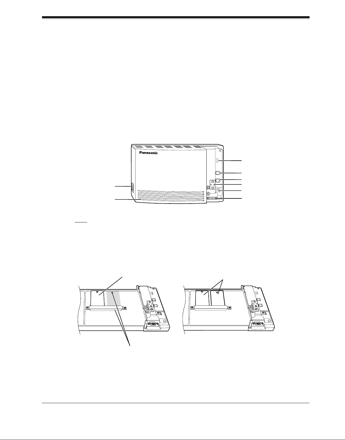
1.3.2 System Components
Main Cabinet
AC Inlet
Power Indicator
POWER
VOICE PROCESSING SYSTEM
VOICE PROCESSING SYSTEM OVERVIEW
MODE (DIP Switch)
Port 1
Port 2
Ferrite Core
Ground Terminal
RS-232C
Connector
Note
EIA port is at SELV.
Inside View of the Main Cabinet
KX-TVS50 KX-TVS80
Memory Card
Position for Optional Expansion Memory Card
Memory Card
Master
Slave
Installation Manual 19
Page 20
VOICE PROCESSING SYSTEM OVERVIEW
System Components
AC Inlet:
Connects the power cable to an AC outlet dedicated to the VPS.
Power Indicator:
Indicates the system status: when flashing, the system is off-line (not ready to receive calls).
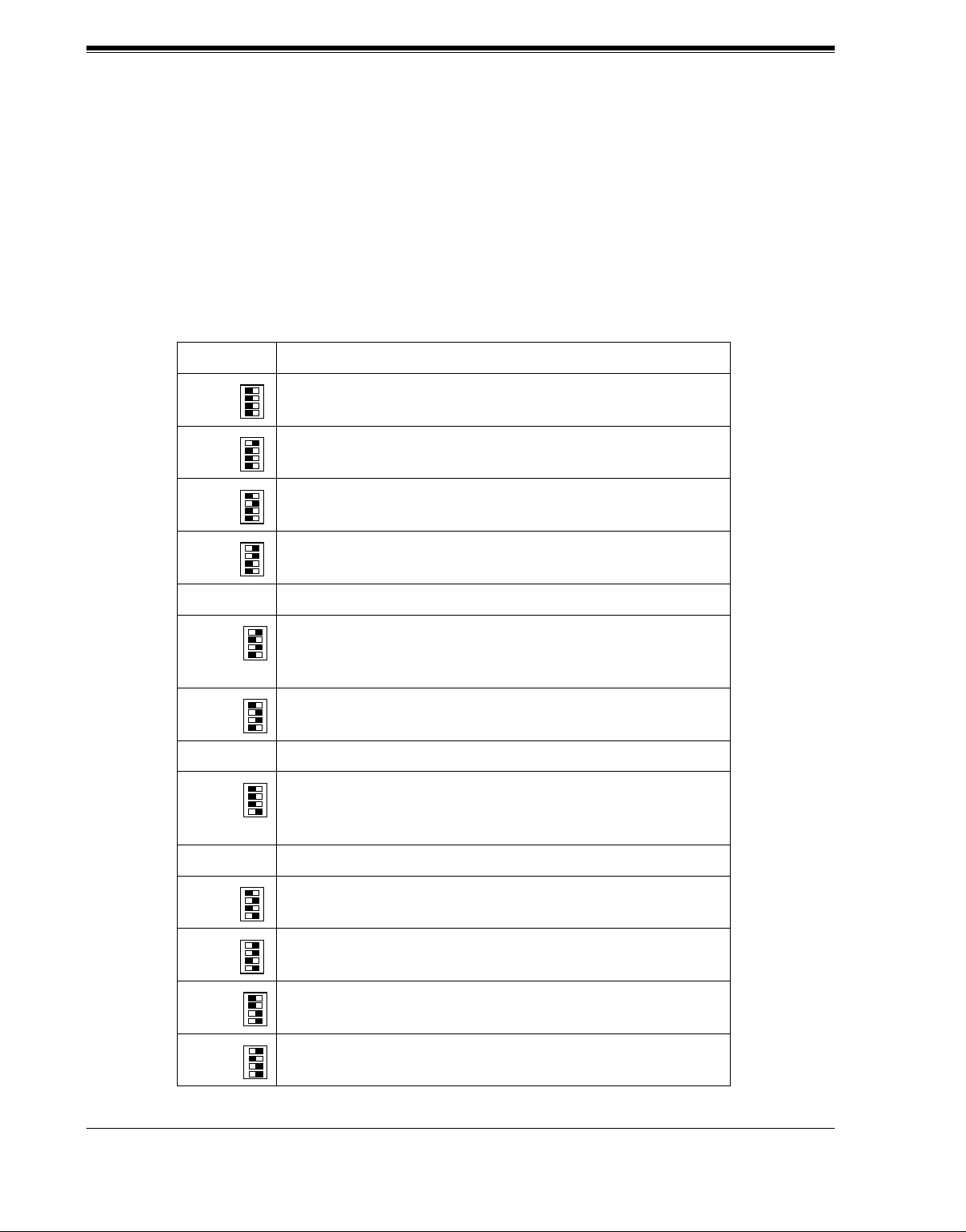
MODE (DIP Sw itch):
(Check the status of this switch only at start-up.) Provides the following additi onal functions:
Position Additional Function
01
•1
01
0 Normal setting. (All switches in 0 position.)
1
•2
01
•3
01
•4
01
•1
Initializes RS-232C parameters.
01
•2
01
•3
01
RS-232C default parameters: 9,600, N, 8, 1
•4
Table 1
01
•1
Auto Configuration is automatically executed and all ports are
01
2*
3*
1
1
•2
01
•3
01
set for Automated Attendant service.
•4
01
•1
Auto Configuration is automatically executed and all ports are
01
•2
01
•3
01
set for Vo ice Mail service.
•4
4Reserved.
01
1•
Initialize s the VPS. Clears all voice data (exc ept User 1 and
01
2•
01
3•
01
5
4•
User 2 prompts) and returns all system parameters to the default
setting.
01
1•
01
6 Test Mode (Hard Disk Drive Read/Write Test)
2•
01
3•
01
4•
7Reserved.
01
1•
Initializes the VPS. Clears all voice data and returns all system
01
2•
01
8
3•
parameters to the default setting.
01
4•
CAUTION: User 1 and User 2 Prompts will be erased!
9Reserved.
01
•1
Auto Configuration is automatically executed and all ports are
01
10*
11*
2
2
•2
01
•3
01
set for Automated Attendant service.
•4
01
•1
Auto Configuration is automatically executed and all ports are
01
•2
01
•3
01
set for Vo ice Mail service.
•4
01
1•
All service prompts are set to System P rompts (factory-r ecorded
01
12
13 All service prompts are set to User 1 Prompts (not recorded).
2•
01
3•
01
4•
English prompts).
01
1•
01
2•
01
3•
01
4•
20 Installation Manual
Page 21

VOICE PROCESSING SYSTEM OVERVIEW
Table 1
Position Additional Function
01
1•
01
14 All service prompts are set to User 2 Prompts (not recorded).
2•
01
3•
01
4•
15 Reserved.
*1 For Panasonic KX-T series telephone systems with DPT Integration.
2
For Panasonic KX-TA624 telephone system with APT Integration.
*
To change the position, use a pointed object, such as a pen, etc.
When setting the DIP Switch to any position (except 0):
1. Disconn ect the station wire(s) an d wait a few minutes.
2. Disconnect the AC cord from the VPS.
3. Set the DIP Switch.
4. Connect the AC cord to the VPS.
5. Connect the station wire(s) to the VPS and wait approximately 3.5 min.
6. Return the DIP Switch to position 0.
Ground Terminal:
Should be connected to a ground source with less than 1 resistance.
RS-232C Connector:
Connects an ASCII or VT terminal to the VPS that is necessary to program the system.
Memory Card:
(One/system) Stores the proprietary system program, and the voice prompts (about 30 min
worth); has the capacity to record approximately 2 h (KX-TVS50) or 6h (KX-TVS80) of
messages from callers.
Optional Expansion Memory Card (for the KX-TVS50):
The KX-TVS52 can expand the flash memory capacity of the KX-TVS50 by 2 h.
1.3.3 Which Phone Systems are Compatible?
We recommend integration with the following Panasonic phone systems:
• Panasonic KX-TA624
• Panasonic KX-TD308
• Panasonic KX-TD1232
• Panasonic KX-TD816
• Panasonic KX-TA1232
Installation Manual 21
Page 22

VOICE PROCESSING SYSTEM OVERVIEW
• Panasonic KX-TD500 (Available for the KX-TVS80 only)
• Panasonic KX-T336
• Panasonic KX-T123211D
We cannot guarantee adequate integration of the VPS with other PBX systems or with Key
Systems. If the customer does not have a recommended Panasonic PBX system, be sure that
the system has the features listed below.
The PBX should have the following features for successful integration:
• Single line (tip/ring) port circuits (Some PBXs need an OPX card to provide this
connection.)
• Station to station touchtone signaling
• Message Waiting Notification from an SLT (single-line telephone)
• Screened transfer from an SLT
• Message Waiting Notification on proprietary (multi-line) sets (message waiting lamp
accessed by dialing on/off codes)
If the PBX does not have these features, VPS operation will be limited.
See 3.1.4 PBX Requirements for In tegration. You will find the following information about
each feature listed:
• Description
• Limitations of the system without the feature
• Tests to determine whether the PBX has the feature
VOICE MAIL
The recommended Panaso nic PBX syst ems ha v e Fol lo w- on ID and Inba nd Integration. When
callers are transferred to an extension that is forwarded to Voice Mail, Follow-on ID sends
callers directly to the mailbox. Without Follow-on ID, the caller would have to re-enter the
mailbox number when connected to Voice Mail.
Touchtone Integration enables the VPS to recognize the current state of the call and improve
its call handling performance. When enabled, the PBX informs the VPS of the status of the call
(busy, answered, ringing, etc.) by sending a code with touchtones before sending the normal
call progress tones. For example, when a caller hangs up before making a selection, the PBX
sends # 9 to the VPS port that answered. This informs the VPS that the caller has hung up.
Upon receiving these digits, the VPS goes on-hook and is ready to handle another call.
Digital (APT/DPT) Integration is available when the VPS is connected to a Panasonic KXTA624 or other Panasonic KX-T ser ies digi tal PBX (depe nding on the so ftw are v er sion) . This
Digital Integration provides the VPS with more information than T ouchtone Integration. This
information enable s the system to identif y the extension num ber of the caller , know where fr om
and why the call is forwarded, and recognize what the caller wants to do. Some features are
available only with Digital Integration (Remote Call Forwarding Set, Live Call Screening,
Two-Way Recording, Two-Way Transfer, Direct Mailbox Access, Intercom Paging, Auto
Configuration, Caller Name Announcement [system/personal], Caller ID Call Routing,
Personal Greeting for Caller ID, Time Synchronization with PBX).
22 Installation Manual
Page 23

VOICE PROCESSING SYSTEM OVERVIEW
1.3.4 Installer Equipment and Software Requirements
The installer must h ave a laptop computer or data terminal equipped with terminal emulation
software. We suggest that you use something like HyperTerminal by HILGRAEVE. Use the
computer to program the VPS. Terminal emulation software enables the keyboard to be used
as a data entry device.
While both the laptop and data terminal are working, the laptop allows screens to be saved in
a file throu ghou t the process. It is often helpful to retrieve these files later if technical support
is needed.
1.3.5 Specifications
Table 2
Ports: 2 ports
Voice Storage (approximate): • KX-TVS50: 2 h
• KX -TVS80: 6 h
Custom Services: 100
Message Retention: 1 to 30 days or unlimited
Number of Mailboxes: • KX-TVS50: 30 Subscriber and 2 Manager
Mailboxes
• KX -TVS80: 62 Subscriber and 2 Manager
Mailboxes
Number of Messages per Mailbox: 100 maximum (programmable)
1.3.6 Hardware
• 1 (KX-TVS50) or 2 (KX-TVS80) Flash Memory Card(s).
• 1 Optional Flash Memory Position for KX-TVS52 card (KX-TVS50 only)
• 2 Telephone Inputs (RJ11C)
• 1 RS-232C Connector
• 1 DIP Switch (4-bit)
1.3.7 Flash Memory Expansion Capabilities (KX-TVS50 only)
Expansion of the flash memory capacity requires an optional expansion memory card (KXTVS52). The KX-TVS50 initiall y h as 2 h memory. The KX-TVS52 increases the capa ci ty by
2 h.
Installation Manual 23
Page 24

VOICE PROCESSING SYSTEM OVERVIEW
1.3.8 Recommendations for System Configuration
General guideline: a ratio of 6/1 (for every 6 lines, 1 port). There are 2 questions to ask when
considering how many ports are desirable:
• Ar e the ports answering all incoming calls or just forwarded/transferred call s?
• If they are answering incoming calls, how busy are the lines?
The guideline abo ve ( 6/1) usuall y works wel l with modera te traf f ic. Ho we ver , this may ha v e to
be modified for heavy traffic. Recommendations are outlined in the following charts.
Table 3
CO Lines Port
1-6 1
7-12 2
One port may not support an Automated Attendant configuration with 5 CO lines. The
preceding recommendat ions for Automated At tendant ports may ha ve to be modi fied for he avy
traffic.
Table 4
CO Lines Port
1-4 1
5-8 2
24 Installation Manual
Page 25
1.4 DIGITAL INTEGRATION
1.4.1 General
There are 2 types of Digital Integration: APT Integration and DPT Integration.
APT Integration is available when the VPS is connected to a KX-TA624. DPT Integration is
available when the VPS is connected to a KX-TD or KX-TA1232 digital PBX.
1.4.2 APT Integration
To the Panason ic KX-TA624, the VPS ports look l ik e prop ri etar y telepho nes. The PBX think s
that the VPS is a proprietary telephone, and the VPS mimics all actions of a proprietary
telephone. Communication bet ween the VPS and the PBX through digital inte gration r equires
the proper software level in the PBX and 4-wire connections for each port. To communicate
between the VPS and the PBX through APT Integration, the PBX and VPS must be
programmed to work together.
VOICE PROCESSING SYSTEM OVERVIEW
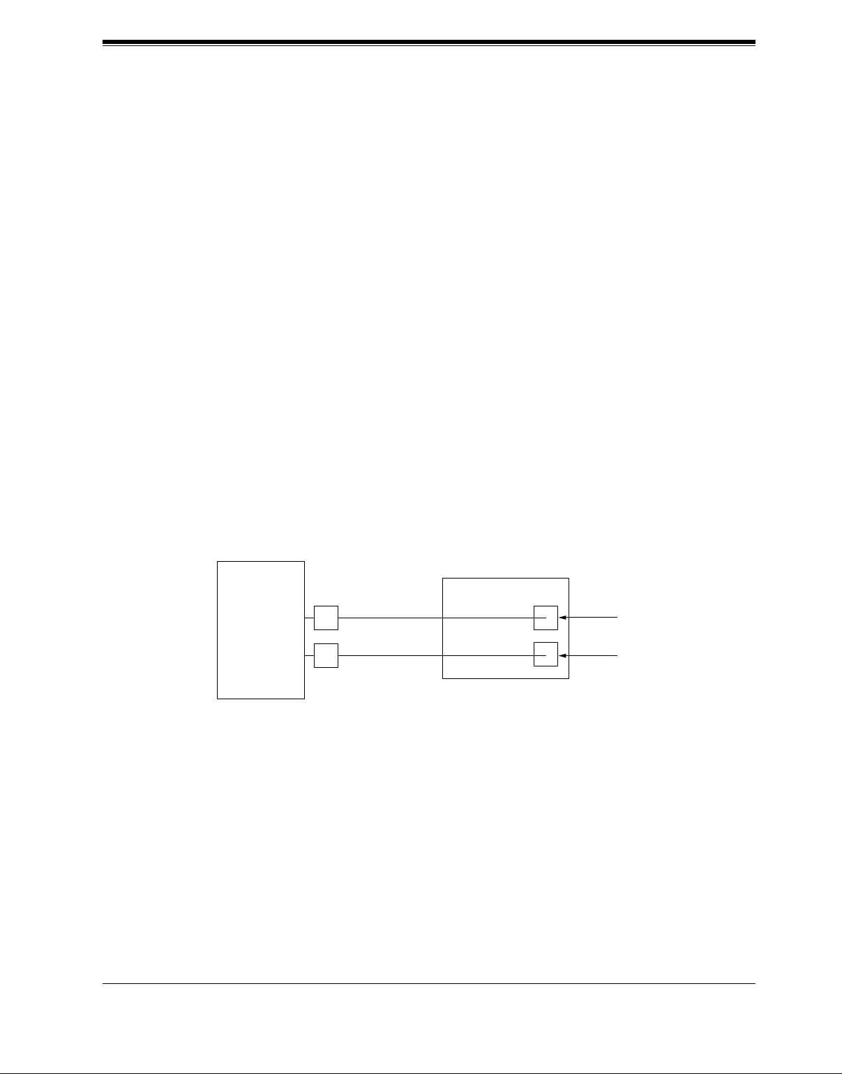
1.4.3 Connection Example—APT Integration
For example, you can connect jack 7 of the KX-TA624 to Port 1 of the VPS with a 4-wire
connection (see dia gram be low). This connection c reate s 1 Voice Mail extension and c an onl y
answer 1 call. This means tha t a ful ly-conf igured 2-port s ystem requ ires 2 j acks fr om the PBX.
VPS
KX-TA624
When APT Integration is acti vate d, a single ex tension jack pr ovides 1 sin gle-lin e interfa ce at a
Port on the VPS. For exa m ple , when 1 l ine cor d (4 wi re) is connected to Port 1 on the VPS, 1
extension is provided.
7
8
Port 1
Extension 107
Port 2
Extension 108
Installation Manual 25
Page 26
VOICE PROCESSING SYSTEM OVERVIEW
1.4.4 DPT Integration
To the Panasonic KX-T seri es PBX that uses DPT Integration, the VPS ports look li ke digital
extensions. The PBX think s that the VPS is a digital phone , and the VPS mimics al l actions of
a digital set. Anot her advanta ge of digital i ntegration i s that the 2B+D communicat ion provides
2 VPS ports for each Digital Station port. Communication between the VPS and the PBX
through digital integration requires the proper software level in the PBX and 4-wire
connections for each port. To communicate between the VPS and the PBX through DPT
Integration, the PBX and VPS must be programmed to work together.
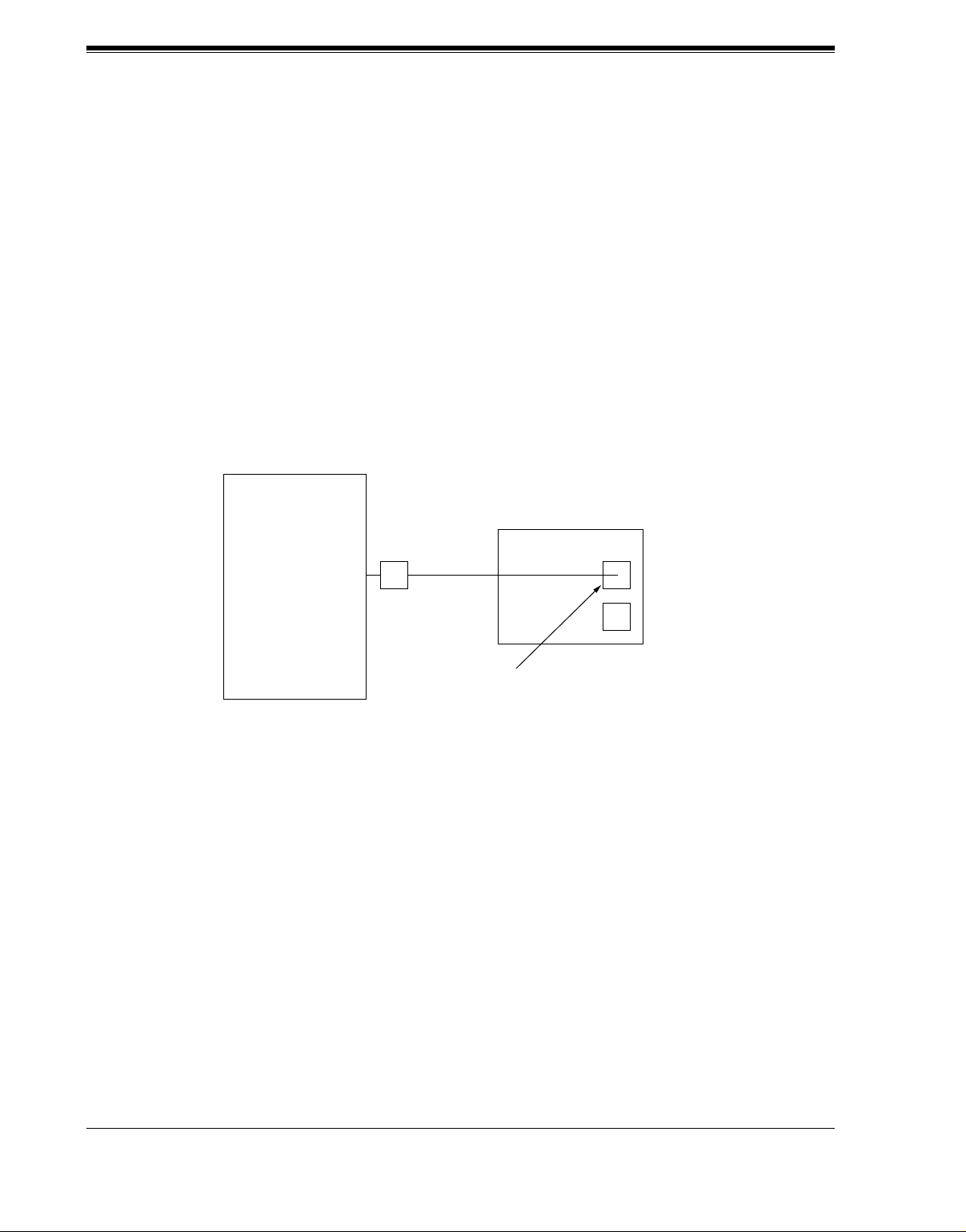
1.4.5 Connection Example—DPT Integration
For example, you can connect jack 15 of the KX-TD1232 to Port 1 of the VPS with a 4-wire
connection (see diagram below). This connection creates 2 Voice Mail extensions and can
simultaneously an swer 2 call s. Thi s means t hat a full y-configured 2-port syst em req uires only
1 jack from th e PBX.
VPS
KX-TD1232
When DPT Integration is activated, a single extension jack provides 2 single-line interfaces at
a Port on the VPS. For example, when 1 line cord (4 wire) is connected to Port 1 on the VPS,
2 extensions are provided.
15
Port 1
Extensions 165 and 166
26 Installation Manual
Page 27

INSTALLATION
Section 2
INSTALLATION
Installation Manual 27
Page 28

INSTALLATION
2.1 SAFETY PRECAUTIONS
Please read the following precautions before installing the VPS.
2.1.1 Installation
The VPS needs to be mounted on a wall. Improper placement of the system may result in
malfunction, noise, or discoloration. Avoid installing the VPS in the following places:
• in direct sunlight; in hot, cold, or humid places
• in new areas where there are thermal springs, etc . (where sulfuric gas ma y dama ge the
equipment or contacts).
• where shocks or vibrations are frequent or strong.
• in dusty places or places where water or oil may come in contact with the unit.
• near high frequency generating devices such as sewing machines, elevators or electric
welders.
• on or near computers, telexes, or other office equipment; near microwave ovens or air
conditioners. (Idea lly , the VPS sho uld not be in the room with these items and should be
at least 1.8 m {6 feet} away from televisio ns.)
Do not obstruct the areas aro und the PBX and the VPS. Both re quire space abo ve for cool ing
and space on the sides for maintenance and inspection.
28 Installation Manual
Page 29

2.1.2 Wiring
• To assure good quality telephone connection, it is recommended new and modifications to
existing installation of customer premise wiring shall use solid twisted pair copper
conductors with minimum 24 gauge that comply with the electrical specifications for
Category 3 wiring as detailed in ANSI/EIA/TIA-570A Building Wiring Standards.
• Do not wire the telephone c able para llel to an A C power sour ce , computer, etc. If cables a re
run near those wires, shield them with metal tubing or use shi elded cables and grou nd the
shields.
• Use protectors if running cables on the floor. Avoid running cables under carpets.
• Avoid sharing a 120 V A C power supply for comput ers, tele xes, and ot her off ice eq uipment
with the VPS. Induction noise from such equipment may interrupt the VPS operation.
When making any connections or removing the cover, be sure the power switch is turned off.
When installing telephone wiring, basic safety precautions should always be followed to
reduce the risk of fire, electric shock and injury to persons, including the following:
• Never install telephone wiring during a lightning storm.
• Never install telephone j acks in wet locatio ns unless the jack i s specif ically designed for
wet locations.
• Never touch uninsula ted telepho ne wires or t erminals unl ess the tel ephone line has been
disconnected at the netw or k in te rface.
• Use caution when installing or modifying telephone lines.
INSTALLATION
Note
If you live i n an area th at can have frequent po wer f ailures, we strongly reco mmend that you
purchase a suitable UPS (unint erruptibl e po wer suppl y) for yo ur VPS (and PBX if needed) .
The power rating of your VPS may be found in the specifications.
Installation Manual 29
Page 30

INSTALLATION
2.2 UNPACKING
Unpack the box and check the items below.
Table 5
Main Unit 1
AC Cord 1
Screws (Wall Mounting) 3
Anchor Plugs (Wall Mounting) 3
30 Installation Manual
Page 31

2.3 MOUNTING THE VPS ON THE WALL
The wall where the VPS is to be mounted must be able to support the weight of the VPS. If
screws other than the ones supplied are used, use the same-sized diameter screws as the
enclosed ones.
To Mount on a Wooden Wall:
1. Place the template (included) on the wa ll to mark the 3 screw positions.
Template
INSTALLATION
2. Install the 3 screws (included accessories) into the wall.
Wooden
Wall
Drive the screw
to this position.
3. Hook the unit on the screw heads.
Installation Manual 31
Page 32

INSTALLATION
2.4 FRAME GROUND CONNECTION
IMPORTANT!!!
Connect the frame of the main unit to the ground.
1. Loosen the screw .
2. Insert the groundi ng wir e.
3. Tighten the screw.
4.
Connect the grounding wire to the ground.
In most of North America, t he gro und pro v ided by the "T hird wire groun d" at the commerci al
or residential power outlet will be satisfactory. However, in some cases this ground may be
installed incorrectly. Therefore, the following test procedure should be performed.
Test Procedure
1. Obtain a suitable voltmeter and s et it for a possible reading o f up to 250 V AC.
2. Connect the meter probes between the 2 main AC voltage points on the wall outlet. The
reading obtained should be 108 V AC-132 V AC.
3. Move one of the meter probes to the third prong terminal (GND).
Either the same reading or a reading of 0 V should be obtained.
4. If a reading of 0 V at 1 terminal and a readi ng of 108 V A C- 132 V A C at the ot her termina l
is not obtained, the outlet is not properly grounded. This condition should be corrected by
a qualified electrician (per article 250 of the National Electrical Code).
5. If a reading of 0 V at 1 terminal and a readi ng of 108 V A C- 132 V A C at the ot her termina l
is obtained, then set the meter to the "OHMS/RX1" scale, place 1 probe at the GND
T e rmin al and the ot her pr obe at the t ermina l which g a v e a re ading o f 0 V. A reading of less
than 1 should be obtained. If the reading is not obtained, the outlet is not adequately
grounded. See a qualified electrician.
VOICE PROCESSING SYSTEM
POWER
To ground
32 Installation Manual
Page 33

2.5 INSTALLATION STEPS
The following is an overview of the standard installation process using Digital Integration.
When necessary, other sections in this manual have been referenced for more detailed
descriptions or instructions.
1. Obtain a list of current users, their extension numbers, their departments, and the type of
systems they use (mailbox, no mailbox, beeper, car phone, etc.).
2. Assess your customers' needs before setting up the syst em. You will save yourself time later
by giving customers what the y need up front . Ask the of fice manager how the VPS will be
used. Give examples.
Recommend that your customer use a word processor to log the greetings. You will find
these files much more easily than the worksheet pages if you need to make changes down
the road.
3. Connect the power cord to the VPS.
INSTALLATION
CAUTION
The power supply cord is used as the main disconnec t device. Ensure that the socket-outlet
is located/installed near the equi pment and is easil y acces si ble .
4. Standard Initialization (For Digital Integration Connection)
a) Program the ports of the PBX for v oice pro cessing (see Section 4 INTE GRATING THE
VPS WITH THE PANASONIC KX-TA SERIES PBX AND KX-TD SERIES PBX).
Program the KX-TA624, the KX-TD1232, the KX-T A1 232, the KX-TD816, the KXTD308 or KX-TD500 for Voice Mail integration.
• KX-TA624
• KX-TD816, KX-TD1232, KX-TA1232, KX-TD308, KX-TD500
Program may be performed on-site or at the office.
All memory is stored and will be retained when the unit is powered up as long as
the DIP Switch has been reset to position [0] prior to turning the unit off.
b) Unplug the power cord of the VPS.
c) Plug station wire(s) from the PBX into VPS (see 2.7 CONNECTIONS).
d) Connect the computer to the VPS with a Null Modem Cable (see 2.8.2 Connecting the
RS-232C Cable).
e) Set the DIP Switch to position 5.
f) Plug in the power cord of the VPS.
g) Wait until the "warning" appears on the screen.
h) Set the DIP Switch back to position 0.
Installation Manual 33
Page 34

INSTALLATION
CAUTION
If the DIP Sw itch is not reset to position 0 after initialization, all programming will be
lost when the voice processor loses power!
5. Perform Quick Setup (see Section 5 CUSTOMIZING THE SYSTEM).
6. Check Quick Setup:
• The Power Indicator on the Voice Processor should be solid.
• The screen output should be: [On Line].
If you do not see the "On Line" message, check the following:
• The line cord to the Voice Processor has 4 conductors.
• The programming on the KX-TA624 is correctly set in System Program [130], or
[130] and [131].
• The programming on the KX-TD816, KX-TD1232, KX-TA1232 or KX-TD308 is
correctly set in System Program [117].
• The programming on the KX-TD 500 is correctly set in the "1-4 VPS (DPT) Por t
Assignment" screen.
7. Set up Class of Service (COS) for each user. Customize voice prompts if necessary (see
Appendix B SYSTEM ADMINISTRATOR'S GUIDE).
8. Perform Administrative Program through a computer (see Appendix B SYSTEM
ADMINISTRATOR'S GUIDE).
CAUTION
Do not turn the power off while the VPS is activated so as not to cause malfunction.
To turn the power off after installing the VPS, unplug the power cord from the VPS a
few minutes after disconnecting station wire(s).
34 Installation Manual
Page 35

INSTALLATION
2.6 INSTALLING AN OPTIONAL EXPANSION
MEMORY CARD (KX-TVS52) TO THE KXTVS50
2.6.1 General
The flash memory capacity of the KX-TVS50 can be increased from 2 h to 4 h if an optional
expansion memory card (KX-TVS52) is installed.
2.6.2 Installing the KX- T VS5 2
1. Disconnect the station wire(s). Wait a few minutes, and then disconnect the AC cord from
the VPS.
2. Take out the screw.
Screw
VOICE PROCESSING SYSTEM
POWER
3. Remove the cover by pressing both tabs and lifting up.
VOICE PROCESSING SYSTEM
POWER
Installation Manual 35
Page 36

INSTALLATION
4. Take out the screws and remove the metal bar.
Screws
Metal Bar
5. Attach the optional expansion memory card firmly. Secure the screw.
Screw
SLAVE
CAUTION
Do not attach t he opt ional e xpansi on memory card at the "MASTER" posi tion. Attac h i t at t he
"SLAVE" position.
6. Replace the metal bar and secure the screws.
Screws
7. Replace the cover and secure the screw.
8. Connect the AC cord to the VPS again.
36 Installation Manual
Page 37

2.7 CONNECTIONS
2.7.1 Connecting to the PBX
The VPS can be connected to up to 2 extension ports of the PBX. Use a 4-conductor wire for
connection with KX-TA624 that uses APT Integration, and for connection with KX-T series
systems that use DPT Integration. Use a 2-conductor wire for connection to all other PBXs.
4-Conductor Cable
Y
G
R
B
Modular Connection
B: BLACK
R: RED
G: GREEN
Y: YELLOW
Outer Pins
Inner Pins
INSTALLATION
Y
G
R
B
RJ-11
Terminal wire
L5
T4
R3
H2
2.7.2 Opening the Ferrite Core
Insert your finger into the opening of the ferrite core and open it as shown below:
Connect a 4-conductor cable or 2-conductor cable to the VPS and run the cable through the
ferrite core (see the following sections). Close the ferrite core.
RJ-11
Installation Manual 37
Page 38

INSTALLATION
2.7.3 Connection for APT Integration
Ports 1-2 of the VPS
Telephone Line
Modular Jacks
PORT 1
PORT 1
PORT 2
PORT 2
Extension Jacks 07 and 08
To Extension
Port of the PBX
Y
G
R
B
(or 15 and 16)
2.7.4 Connection for DPT Integration
Ports 1-2 of the VPS
Telephone Line
Modular Jacks
To KX-TA624
Y
G
R
B
PORT 1
PORT 1
PORT 2
PORT 2
To a KX-T series PBX that uses DPT Integration
Any Extension Jack except Jack 01
To Extension
Port of the PBX
Y
G
R
B
Y
G
R
B
38 Installation Manual
Page 39

2.7.5 Connection for Non-APT/DPT Integration
Ports 1-2 of the VPS
Telephone Line
Modular Jacks
PORT 1
INSTALLATION
PORT 1
PORT 2
To Extension
Port of the PBX
PORT 2
To Extension Ports of
Non-APT/DPT Integration PBX
G
R
G
R
Installation Manual 39
Page 40

INSTALLATION
2.8 TERMINAL CONNECTION
2.8.1 Requirements for Connecting Programming Terminal
The programming terminal must be connect ed with a se rial cable with an RS-232C co nnecto r
at the RS-232C port. This must be a null modem cable. This enables system administration
(system setup, mailbox setup, and system diagnosis) to be performed.
Communication parameters of the VPS have been set to the following values at the factory:
Table 6
COMMUNICATION PARAMETERS
Baud Rate: 9600 bps
Word Bit Length: 8 Bits
Parity: None
Stop Bit Length: 1 Bit
2.8.2 Connecting the RS-232C Cable
RECOMMENDED:
Before connecting the cable, switch off the power on both the data terminal and the VPS.
VOICE PROCESSING SYSTEM
POWER
Insert the RS-232C cable into the VPS with the connector indicating the same direction.
The cable must be shielded and no longer than 2 m {6.5 feet}.
40 Installation Manual
Page 41

INSTALLATION
VPS (9 pin)
Circuit
type
(EIA)
BB
BA
CD
AB
CC
VPS (9 pin)
Circuit
type
(EIA)
Signal
name
RXD
TXD
DTR
SG
DSR
Signal
name
Pin
no.
2
3
4
5
6
Pin
no.
9-pin Cable Printer/IBM®-PC
Pin
no.
2
3
4
5
6
7
8
name
RXD
TXD
DTR
DSR
RTS
CTS
SG
type
(EIA)
BB
BA
CD
AB
CC
CA
CB
Circuit
Signal
25-pin Cable Printer/PC
Circuit
Signal
Pin
no.
name
type
(EIA)
BB
BA
CD
AB
CC
RXD
TXD
DTR
SG
DSR
Pin
Number
1
2
3
4
2
3
4
5
6
1
3FGRXDAABB
2
TXD BA
20
DTR
7
SG
5
CTS
6
DSR
8
DCD
CD
AB
CB
CC
CF
Table 7 Pin Configuration of the RS-232C
Circuit Type
Signal Name
RS-232C CCITT
FG
TXD
RXD
RTS
Frame Ground
Transmitted Data
Received Data
Request To Send
AA
BA
BB
CA
101
103
104
105
Installation Manual 41
Page 42

INSTALLATION
Table 7 Pin Configuration of the RS-232C
Pin
Number
6 DSR Data Set Ready CC 107
7
8
20 DTR Data Terminal Ready CD 108.2
SG
DCD
Signal Ground
Data Carrie r Detect
2.8.3 RS-232C Signals
Frame Ground (FG)
Connects an external ground to the unit frame, usually the ground pin of the AC power cord.
Transmitted Data (TXD)—output
Conv eys s ignals from t he unit to the termina l/printer. A "mark" condition is held unl ess data or
BREAK signals are being transmitted.
Received Data (RXD)—input
Conveys signals from the terminal/printer to the unit.
Signal Name
Circuit Type
RS-232C CCITT
AB
CF
102
109
Request To Send (RTS)—output
This lead is held on whenever DS R is on.
Signal Ground (SG)
Connects to the DC ground of the unit for all interface signals.
Data Terminal Ready (DTR)—output
This signal line is turned on by the unit to indicate that it is RS-232C on-line. Circu it DTR ON
does not indicate that communication has been established with the terminal/printer. It is
switched off when the unit is RS-232C off-line.
42 Installation Manual
Page 43

INTEGRATING THE VPS WITH PANASONIC KX-T PHONE SYSTEMS
Section 3
INTEGRATING THE VPS WITH
PANASONIC KX-T PHONE SYSTEMS
Installation Manual 43
Page 44

INTEGRATING THE VPS WITH PANASONIC KX-T PHONE SYSTEMS
3.1 GUIDELINES FOR INTEGRATION
3.1.1 APT/DPT or Inband Signaling?
There are 3 types of integration available on the VPS: Inband Signaling, APT and DPT. The
VPS used with any other brand of telephone equipment requires inband equipment.
KX-TA624 that can use APT Integration is:
• KX-TA624 Version Y581A or higher.
KX-TD series PBXs that can use DPT Integration ar e:
• KX-TD308 Version P871F or higher
• KX-TD816 Version P301O or higher
• KX-TD1232 Version P231U or higher
• KX-TD500 Version Q171A or higher
Likewise, the KX-TA1232 can also use DPT Integration:
• KX-TA1232 Version P831AA or higher (all versions)
Notes
• To the VPS, the KX-TA1232 looks identical to the KX-TD1232.
• Depending on the model and/or the software version of the connected PBX, you may
not be able to utilize some of the features available only with DPT Integration (see
4.1.1 Why Digital Integration is Important). For more information, call Na tional
Parts Center at 1-800-833-9626.
3.1.2 Why Integration is Important
The VPS works well with most PBXs because its connections are made through a standard
single-line (tip/ring) telephone interface. However, the VPS operation depends on the
capabilities and featur es provide d by the PBX; its performanc e will va ry when connected wit h
different PBX systems. For example, Follow-on (or C alled Party) ID is a feature of the PBX.
If the PBX does not have this feature, the VPS cannot transfer calls directly to the correct
mailbox and play the Busy or No Answer greeting for that mailbox.
3.1.3 How the VPS and the PBX Communicate
T o the PBX, the VPS looks lik e SLT sets. The PBX thinks that the VPS is an SLT , and the VPS
mimics all actions a live attendant would carry out from an SLT.
For the VPS and the PBX to communicate, proper signaling is important. Like an attendant,
the VPS places calls by going off-hook and dialing numbers. It starts call transfers with a
hookswitch flash to put callers on hold and then dials the extension number. By recognizing
call progress tones from the PBX, the VPS decides how calls should be handled. Inband
44 Installation Manual
Page 45

INTEGRATING THE VPS WITH PANASONIC KX-T PHONE SYSTEMS
Integration allows the PBX to send certain digits (touc htone) to the VPS, allowing it to
recognize the status of the extension and take the appropriate action.
Table 8
VPS/PBX COMMUNICATION
PBX to VPS
Call Progress Tones
• ringback
• busy
• reorder
Touchtones
The VPS must also have access to certain PBX features. For example, if the VPS takes a
message, one way it can notify the mailbox owner is by dialing the PBX's Message-WaitingLamp-On code. Once n ew messages are r etrieved, the VPS dials the Mess age-Waiting - LampOff code for that same mailbox owner.
VPS to PBX
SLT Signals
• on/off hook
• hookswitch flash
• touchtones
3.1.4 PBX Requirements for Integration
The PBX must have certain capabilities and features to work with the VPS. (Although this
section includes tests to help you evaluate the PBX, it may be necessary to refer to the PBX's
documentation for detailed capability and feature descriptions.)
Single Line (Tip/Ring) Port Circuits
The VPS can only be connected to a PBX that supports SLT sets. Some PBXs need an OPX
card to provide this connection. However, some OPX cards do not provide all the cap abiliti es
listed in this section.
Following are the minimum current and voltag es that the PB X must supply:
Table 9
Minimum Loop Current 20 mA
Minimum Line Voltage 7 V DC
Minimum Ringing Voltage 40 V AC
Station to Station Touchtone Signaling
For system users to access VPS services and features, they must be able to send touchtones
from their telephones to the VPS port. As a general rule, SLT sets can perform station-tostation touchtone signaling; however, many proprietary telephones cannot. Some PBXs need
to be programmed to make proprietary sets use touchtone signaling.
Installation Manual 45
Page 46

INTEGRATING THE VPS WITH PANASONIC KX-T PHONE SYSTEMS
If the PBX does not provide station-to-station touchtone signaling, VPS services and
features will be limited.
TEST:Call an SLT extension from the telephone in question. When the call
is answered, see if the person receiving the call hears touchtones when
numbers are dialed.
Message Waiting Notification from an SLT
The PBX extensi ons should light a lamp or r eceiv e stutter di al tone when t he Message-WaitingLamp-On code is dialed by the VPS. The VPS functions best when the extension number of
the voice mailbox o wner follo ws the Light-On or Light -Off code. On some PBXs, ho wev er , the
extension number is dialed first, followed by a hookswitch flash and then the On code. This
presents a problem if the extension is answered before the VPS sends the hook-switch flash.
If the PBX does not provide message waiting notification from an SLT, the VPS can only
notify mailbox owners by dialing a beeper number or user-assigned extension.
This process sl ows do wn VPS performance as it dials the beeper or ex tension number and wa its
to confirm noti fica tion. The beeper or user -a ssigned e xtensi on notif icat ion is meant t o be used
for necessity, usually for mailbox owners who are often out of the office (e.g., sales people or
field representatives). The only other option, without message waiting notification, is for
mailbox owners to periodically call the VPS to check for messages.
TEST: See if dialing the On code from an SLT can turn on an extension's
message waiting indicator.
Screened Transfer from an SLT
The PBX must provide a screened transfer from an SLT for the VPS to function properly.
A screened transfer:
Puts the caller on hold, usually with a hookswitch flash.
1.
Dials the extension.
2.
Checks to see if the calle d subsc riber is in, o ut, or on anot her li ne , and wh ether or not t hat
3.
subscriber accepts the transfer.
Completes the transfer (by going on-hook) or returns to the caller to say that the party is
4.
busy or not available. It then gives the caller an opportunity to leave a message.
If the PBX does not provide screened transfer from an SLT, the VPS cannot give callers the
option to leave a message in a subscriber's mailbox.
46 Installation Manual
Page 47

TEST: Place an outside call from an SLT. See if you can set up a screened
transfer to another extension. Next, try the same test with an internal call.
(The VPS may have to transfer both types of calls.)
Follow-on ID or Called Party ID
When forwarding or transferring a call to the VPS, a PBX with Follow-on ID sends the mailbox
number of the called s ubscriber to the VPS before c onnecting the ca ller. The VPS responds by
playing that subscriber's personal greeting. This operation is sometimes called Call Forward to
Mailbox. W i t hout t h is fe at ure , t he VPS cannot immediately play the greet i ng whe n the line is
busy or there is no answer and allow the caller to leave a message.
INTEGRATING THE VPS WITH PANASONIC KX-T PHONE SYSTEMS
Installation Manual 47
Page 48

INTEGRATING THE VPS WITH PANASONIC KX-T PHONE SYSTEMS
3.2 PBX PARAMETERS AND PORT SETTINGS
3.2.1 General Guidelines and Definitions
Optimal performance of the VPS/PBX system relies on proper VPS programming. There are
3 categories of hardware settings: RS-232C, Port Settings, and PBX Interface Parameters.
Entering a number sets some of the parameters, while others u se sequence c odes.
3.2.2 RS-232C Sett ings
• Baud Rate (300-38400): Specifies the speed at which the data is transferred in bits-per-
second.
• Word Bit Length (7-8): Defines the number of bits in each byte or character.
• Parity (N, O, E): Specifies the parity used for error detection.
• Stop Bit Length (1-2): Specifies the number of bits used to signify the end of the byte.
• Default: 9600, 8, N, 1
3.2.3 Port Settings
There is no need to change these in a typical installation. Only change these parame ters when
connecting the VPS to a PBX other than a KX-T series PBX. Each port on the VPS should
match the type of signali ng the PBX e xpects . If yo u need to chang e these se ttin gs, refe r to the
PBX manual or customer support office to get the correct values for these settings.
• Flash Time—100, 300, 600, 900 ms:
The minimum length of time that the PBX requires to recognize a hookswitch flash.
Choose the amount that is equal to or greater than the PBX's setting.
• CPC Signal (Calling Party Control Signal)—NONE, 6.5, 150, 300, 450, 600 ms:
The length of time allowed for th e short bre ak in loop curr ent that is used to in dicate that
the caller has hung up; usually set to NONE, s ince most PBXs do no t pr o vide this signal
to single line ports. If choosing a setting other than NONE, use an amount equal to or
less than the PBX or telephone company provided CPC signal.
• Disconnect Time—1-8 s:
The length of time that the line is temporarily unavailable after a call has ended.
• Dial Mode—Touchtone, Pulse 10 pps, Pulse 20 pps:
The type of signaling the PBX single line port expects to receive (pps = pulses per
second).
48 Installation Manual
Page 49

INTEGRATING THE VPS WITH PANASONIC KX-T PHONE SYSTEMS
3.2.4 PBX Interface Parameters
Dialing Parameters
• PBX Type:
Specifies the type of PBX which is connected to the VPS.
• Integration Mode:
Specifies the metho d of integration to be used betwe en the VPS and PBX. If PBX type i s set
to the Panasonic KX-T series, the Inband Signaling parameters are set automatically and
should not be altered. APT Integration is only available when a KX-TA624 PBX is
connected and the software is upgraded. DPT Integration is only avai lable when a KX-TD
series or KX-TA1232 PBX is connected and the software is upgraded.
Table 10
SEQUENCE CODES
D Disconnect
F Hookswitch Flash
R Ring Detection
S Silence Detection
T Dialtone Detection
W Wait for 1 Second
X Dial Extension
A: Answer
0-9, , #
• Operator Transfer Sequence:
Tells the VPS how to transfer a call to the operator.
Example: FTX [hookswitch flash—dial tone—dial (opera tor) extn.]
• Extension Transfer Sequence:
Tells the VPS how to transfer a call to an extension.
Example: FTX [hookswitch flash—dial tone—dial extn.]
• Alternate Extension (Transfer Sequence):
T el ls the VPS h ow to tr ansfer a call to an exte nsion that belongs to t he "Altern ate Extensi on
Group". This is useful for extensions that need a special transfer procedure (i.e., blind
transfer) such as modem extensions.
Example: FTXD [hookswitch flash—dial tone—dial extn.—hang up]
• Reconnect Sequence on Busy:
Tells the VPS how to return to the caller if the called e xt en sio n is busy. PBXs di ffer in how
they handle this function. Test from an SLT to determine the sequence.
Touchtone Digits
Installation Manual 49
Page 50

INTEGRATING THE VPS WITH PANASONIC KX-T PHONE SYSTEMS
• Reconnect Sequence on No Answer:
T ell s the VPS how to r eturn to the caller i f the called exte nsion does not answer. PBXs differ
in how they handle this function. Test from an SLT to determine the sequence.
• Reconnect Sequence on Refused Call:
Tells the VPS how to return to the caller if the called extension's owner has enabled Call
Screen ing to not take th e call. PBXs diff er in how the y handle this funct ion. T est f rom an S LT
to determine the sequence.
• Light On Sequence for Message Waiting Lamp:
This is the dialing sequen ce that the VPS must use to turn on a mess ag e waiting lamp at an
extension.
• Light Off Sequence for Message Waiting Lamp:
This is the dialing seq uence th at the VPS must use to turn off a messag e waitin g lamp at a n
extension.
• Call Waiting Sequence:
This sequence is carried out by the VPS to perform call waiting when the called extension
is busy. PBXs differ in how they handle this function. Test from an SLT to determine the
sequence.
• Release Sequence for Call Waiting:
This sequence is carried out by the VPS to release call waiting. PBXs differ in how they
handle this function. Test from an SLT to determine the sequence.
Inband Signaling
These parameters are used when the In tegration Mode is set to Inband. If the PBX type is set
to a KX-T series system, these parameters will be automatica lly set. If anot her type PBX is
used, check that system's installation manual for settings.
Code
(default)
1 Ringback Tone The extension dialed is ringing.
2 Busy Tone The extension dialed is busy.
3
4 DND The extension dialed has set DND feature (Do Not Disturb).
5 Answer The extension dialed is answered.
6
Table 11
Call State Sent to the Voice Mail Port When...
Reorder Tone An invalid extension number is dialed or the call is
inadvertently connected to another Voice Mail port (also
heard when no touchtone receiver is available to the Voice
Mail extension).
Forwarded to V oice
Mail (Ringing)
The extension dial ed is forwarded to Voice Mail and another
Voice Mail port is able to answer. (This lets the first Voice
Mail port, usually an Auto Attendant, send the call to the
other Voice Mail port. )
50 Installation Manual
Page 51

INTEGRATING THE VPS WITH PANASONIC KX-T PHONE SYSTEMS
Table 11
Code
(default)
7
8
9
#9
Call State Sent to the Voice Mail Port When...
Forwarded to Voice
Mail (Busy)
Forwarded to Extn. The extension dialed is forwarded to another non-Voice
Confirmation Tone The Message Waiting Lamp On or Message Waiting Lamp
Disconnect The caller disconnects. The central office must set a CPC
Digit Translation Table Parameters
These parameters allow PBXs that have a fixed Follow-on ID sequence to be used with the
VPS. For example, a Follow-on ID sequence of [ 1001] can be changed to [#61001] by
using these parameters.
• Inter-Digit Time-Out: This parameter defines the inte rval of inc oming sign als (Follow-
on ID) from the PBX to th e VP S. The Digit Translation Table applies the digits received
within this time to translation.
• Input-Output (up to 8 alphanumeric characters): When the system receives digits
within the inter-digit time, it checks them against the input table. If they are found, the
system util izes the outpu t digits in their place.
The extension dialed is forwarded to Voice Mail and no
other Voice Mail ports are a v aila ble to acce pt the call. (Thi s
signals the Voice Mail port [usually Auto-Attendant] to let
the caller to leave a message.)
Mail extension.
Off code is dialed successfully.
signal to the PBX line for this signal to work for outside
calls.
The remainder of this section consists of step-by-step guides for software verification
and programming of the recommended Panasonic PBX systems.
If you (the dealer) have any problem as you go through this section, please call
1-800-211-PANA(7262).
Installation Manual 51
Page 52

INTEGRATING THE VPS WITH PANASONIC KX-T PHONE SYSTEMS
3.3 CONNECTING THE VPS WITH PANASONIC
KX-T SERIES PBXs
3.3.1 VPS Programming for Inband Integration
Set parameters from the System Administ ration Terminal. The table below lists recommend ed
parameters for Panasonic KX-T series PBXs.
Table 12
PBX Type Other
Manufac-
Integration
Mode
Operator
Transfer
Sequence
Extension
Transfer
Sequence
Alternate
Extension
Transfer
Sequence
Reconnect
Sequence on
Busy
Reconnect
Sequence on No
Answer
T308/
T616
turers
None None None None None None None None None
Inband Inband Inband Inband Inband Inband Inband Inband
FX (A) FTX
(A)
FX (A) FTX
(A)
FX (A) FTX
(A)
FWW FWW FWW FWW FWW FWW FWW FWW FWW
FWW FWW FWW FWW FWW FWW FWW FWW FWW
T1232 T96 T336 TD816/
TD1232/
TA1232
FTX
(A)
FTX
(A)
FTX
(A)
FTX
(A)
FTX
(A)
FTX
(A)
FTX
(A)
FTX
(A)
FTX
(A)
FTX (A) FTX
FTX (A) FTX
FTX (A) FTX
TD308 T A ser ies TD500
FTX (A) FTX
(A)
FTX (A) FTX
(A)
FTX (A) FTX
(A)
(A)
(A)
(A)
Reconnect
Sequence on
Refuse Call
Light-On
Sequence for
Message
Waiting Lamp
Light-Off
Sequence for
Message
Waiting Lamp
FWW FWW FWW FWW FWW FWW FWW FWW FWW
* N/A T701X# T#91X
* N/A T702X# T#90X T#9X T700X T700X T702X# T700X
T9X
T701X T701X T701X# T701X
52 Installation Manual
Page 53

INTEGRATING THE VPS WITH PANASONIC KX-T PHONE SYSTEMS
Table 12
PBX Type Other
Manufac-
turers
Call Waiting
Sequence
Release
Sequence for
Call Waiting
* Check with manufacturer.
N/A Not Available
(A) Adding "A" for "answer" to the operator and extension transfer eliminates the message:
"You have a call" when the AA transfers a call. The VPS disconnects after line is
answered. Adding "D" for "disconnect" creates a blind transfer.
*N/A1N/AN/A1111
*N/AFN/AN/AFFFF
T308/
T616
T1232 T96 T336 TD816/
TD1232/
TA1232
TD308 TA seri es TD500
3.3.2 KX-T123211D Software Verification and Programming for
Inband Integration
1. Check the software version of the KX-T123211D by using System Program [98], which
shows the software version number:Y201Z940430
The underlined digits rep resent the sof twa re produ ction da te code (format YYMMDD). In
this example, the date cod e is April 30, 1994 (yea r, month, day). For this softw are v ers ion ,
the software production date of the PBX must be April 30, 1994, or later.
If the software production date of the PBX is earlier than 4/30/94, call National Parts
Center (1-800-833-9626) to order a software upgrade.
2.
Enable System Program [80] for each extension connected to the VPS.
This parameter is used to tell the KX-T123211D which extensions are connected to the
VPS. Ports w ith this parameter enabled can receive Follow-on ID and DTMF call status
signaling (busy, answered, disconnect, etc.) if the Voice Mail integration and DTMF
integration features are also enabled.
(TM3)
3. Enable System Program [81] to turn on DTMF Integration. On extensions with the Voice
Mail port parameter enabled, the KX-T123211D can send codes (touchtones) to indicate
call states; this increases VPS efficiency. Codes apply to all transferred calls; outside calls
only indicate disconnect (provided the KX-T123211D is programmed for CPC detection
and the Central Office sends the CPC signal). Refer to the Table 10 in the Section
3.2.4 PBX Interface Parameters.
Installation Manual 53
Page 54

INTEGRATING THE VPS WITH PANASONIC KX-T PHONE SYSTEMS
4. Put all e xtensi ons connec ted to t he VPS into 1 ext ension gr oup using System Progr am [60].
Reserve this extension group for these extensions! Do not mix other extensions into this
group.
5. Enable hunting for the VPS extension group using System Program [08].
6. Set the hunting type for the VPS extension group to circular using System Program [09].
7. At ev ery VPS extension, tempora rily connect an SL T or b utt set, go off-hoo k and dial 7301#
to turn on Data Line Security. This prevents the KX-T123211D from sending Executive
Override or Call Waiting tones to these e xtensio ns. We recommend that all Voice Mail port
extensions have this feature enabled to avoid interruption of recording.
8.
At every user’s extension, go off-hook and dial 7192#. This sets the proper Follow-on ID
sequences so that forwarded calls go directly to the extension’s mailbox. The KX-
T123211D automatically sends the extension’s digits to the Voice Mail port before
connecting the caller.
For Follow-on ID to work :
• Ports connected to the VPS must be assigned as Voice Mail ports.
• Ex tensions must be forwarded to the first port of the Voice M ail (using the Busy/No
Answer mode or the All Calls mode).
• The mailbox number should be the same as the extension number.
Interacti on with other features:
• Call Forwarding—If the extension is forwarded to an extension that is also
forwarded, the forwarding will not work.
• Call Hunting—Hunting does not interfere with Follow-on ID.
• Call Transfer—Calls transferred to an extension with Follow-on ID and call
forwarding enabled will be forwarded directly to the mailbox.
• Data Line Security—We recommend that all Voice Mail port extensions have this
featur e enabled to avoid interrupti on of recor ding by Executive Over ride tone or Call
Waiting tone.
9. Select the appro priat e o utsid e (CO) Li ne fe ature sett ings depe nding on ho w your cu st omer
plans to use the VPS: A) to answer all incoming calls, B) as an operator backup, or C) to
only answer calls not answered by user extensions.
Recommended outside (CO) line feat ure settings:
a) If the VPS is answering all incoming calls:
Outside (CO) Line Mode—Use System Programs [51] and [52] to set this
parameter. Program all lines DIL t o the f irs t e xten sio n of t he Voice Mail hunt group.
The KX-T123211D will allow incoming CO calls to hunt only if the outside (CO)
lines are DIL to t he f irst port of the hun t group. Lines pr ogramed as "Normal" do not
hunt.
54 Installation Manual
Page 55

INTEGRATING THE VPS WITH PANASONIC KX-T PHONE SYSTEMS
b) If the VPS is only answering calls not answered by the operator (Operator Backup):
Flexible Ringing Assignment—For each outside (CO) line, use System Programs
[47] (Day Mode) and [48] (Ni ght Mode) to enable ring ing at the opera tor’s extension
(jack).
Delayed Ringing Assig nment—To give the o perator time to answer th e ca ll before
the VPS picks up, we recommend setti ng the delay to 3 or 4 rings for ea ch e xtension
connected to the VPS. Use System Programs [49] (Day Mode) and [50] (Night
Mode).
Outside (CO) Line Mode—Set the mode for eac h o utside (CO) line to "Normal".
Use System Programs [51] and [52] to set this parameter.
c) If the VPS is only answering calls not answered by user extensions:
Flexible Ringing Assignment—For each outside (CO) line, use System Programs
[47] (Day Mode) and [48] (Ni ght Mode) t o enabl e ringi ng o n e v ery ex ten sion (j ack)
that you want to have ring.
Delayed Ringing Assignment—T o gi ve users t ime to answer the call before the VPS
picks up, we recommend setting the delay to 3 or 4 rings for each extension
connected to the VPS. Use System Programs [49] (Day Mode) and [50] (Night
Mode).
CO Mode—Set the mode for each outside (CO) line to "Normal". Use System
Programs [51] and [52] to set this parameter.
3.3.3 KX-TA Series Programming for Inband Integration via the
Manager’s Extension
Note
If your PBX is the KX-TA1232, please refer to the procedure described in 3.3.5 KX-
TD816, KX-TD1232, KX-TA1232 and KX-TD308 Programming for Inband Integration via
the Manager’s Extension or 3.3.6 KX-TD816, KX-TD1232, and KX-TA1232 Programming
for Inband Integration via the Operating and Maintenance Tool for programming.
1. Enable System Program [102] for each extension connected to the VPS. Jack 07, or jacks
07 and 08 can be assig ned for the VPS1 as th e Voice Mail port. Jack 15, or jacks 15 and 16
can be assigned for the VPS2.
This parameter is u sed to tell the KX-TA series which exte nsions are c onnected to the VPS.
Ports with this parameter enabled can receive Follow-on ID and touchtone call status
Signaling (busy, answered, disconnect, etc.) if the Voice Mail integration and Touchtone
Integration features are also enabled.
2. Enable System Program [103] to turn on Touchtone Integration. On extensions with the
Voice Mail port parameter enabled, the KX-TA series can send codes (touchtones) to
indicate call states; this increases VPS efficiency. Codes apply to all transferred calls;
outside calls only indic ate di sconnec t (pr ov ided t he KX-TA series is program med for CPC
Detection, and the Central Office sends the CPC signal). Refer to the Table 10 in Section
3.2.4 PBX Interface Parameters.
Installation Manual 55
Page 56

INTEGRATING THE VPS WITH PANASONIC KX-T PHONE SYSTEMS
3. Put all extensions connected to the VPS into 1 extension group using System Program
[600].
Reserve this extension group for these extensions! Do not mix other extensions into this
group.
Note
Up to two VPS units can be connected to the KX-TA624. When two VPS units are
connected to the KX-TA624, 2 different extension groups should be assigned for each
VPS in System Program [600]. One extens ion group is f or j ack 07, or jac ks 07 and 08 of
the KX-TA624. The other extension group is for jack 15, or jacks 15 and 16.
4. Enable hunting for the VPS extension groups using System Program [100].
5. Set the hunting ty pe for the VPS ext ension groups to circu lar using Sys tem Progra m [101].
6. At ev ery VPS extension, tempora rily connect an SL T or b utt set, go off-hoo k and dial 7301#
to turn on Data Line Security. This prevents the KX-TA series from sending Executive
Override or Call Waiting tones to these e xtensio ns. We recommend that all Voice Mail port
extensions have this feature enabled to avoid interruption of recording.
7. Select the appropriate outside (CO) line feature settings depending on how your customer
plans to use the VPS: A) to answer all incoming calls, B) as an operator backup, or C) to
only answer calls not answered by user extensions.
Recommended outside (CO) line feat ure settings:
a) If the VPS is answering all incoming calls:
Outside (CO) Line Mode—Use System Pr ograms [414] (Day Mode), [415] (Night
Mode), [416] (Lunch Mode) to set this parameter. Program all lines DIL to the first
extension of the Voice Mail hunt group. The KX-TA series will allow incoming
outside calls to hunt only if th e outside (CO) lines are DIL to the f irst p ort of the h unt
group. Lines programmed as "Normal" do not hunt.
b) If the VPS is only answering calls not answered by the operator (Operator Backup):
Flexible Ringing Assignment—For each outside (CO) line, use System Programs
[408] (Day Mode), [409] (Night Mode) and [410] (Lunch Mode) to enable ringi ng at
the operator’s extension (jack).
Delayed Ringing Assignment —To give the operator time to answer the call before
the VPS picks up, we recommend setting the delay to a few seconds for each
extension connected to the VPS. Use System Programs [411] (Day Mode), [412]
(Night Mode) and [413] (Lun ch Mode).
Outside (CO) Line Mode—Set the mode for each out side (CO) li ne to "Normal".
Use System Programs [414] (Day Mode), [415] (Night Mode) and [416] (Lunch
Mode) to set this paramete r.
c) If the VPS is only answering calls not answered by user extensions:
56 Installation Manual
Page 57

INTEGRATING THE VPS WITH PANASONIC KX-T PHONE SYSTEMS
Flexible Ringing Assignment—For each outside (CO) line, use System Programs
[408] (Day Mode), [409] (Night Mode) and [410] (Lunch Mode) to enable ringing
on every extension (jack) that you want to have ring.
Delayed Ringing Assignment—T o gi ve users t ime to answer the call before the VPS
picks up, we recommend setting the delay to a few seconds for each extension
connected to the VPS. Use Sy stem Programs [411] (Day Mode), [412] (Night Mode)
and [413] (Lunch Mode).
Outside (CO) Line Mode—Set the mode for eac h o utside (CO) line to "Normal".
Use System Programs [414] (Day Mode), [415] (Night Mode) and [416] (Lunch
Mode) to set this parameter.
CAUTION
DO NOT create a mailbox in both VPS for the same extension. Each extension can have a
maximum of 1 mailbox in either VPS. The extension should assign a Voice Mail extension
from the VPS which contains its mailbox as the destination for Call Forwarding and Voice
Mail Transf er. DO NOT assign a Voice Mail extension from the other VPS. For example, if
jack 06 (extension 106) has its mailbox in the VPS1, assign extension 107 or 108 as the
destination, not extension 115 or 116 (see the following diagram).
KX-TA series
6
7
8
Group A
15
16
Group B
Extension 106
VPS1
Port 1
Extension 107
Port 2
Extension 108
Mailbox for Extension 106
VPS2
Port 1
Extension 115
Port 2
Extension 116
Installation Manual 57
Page 58

INTEGRATING THE VPS WITH PANASONIC KX-T PHONE SYSTEMS
3.3.4 KX-TD500 Programming for Inband Integration with KXTVS80
Whenever possible, we recommend that you use DPT Integra tion. Howe ver , in some cases, this
is not possible. In the following situations, you need to use Inband Integration:
• Your PBX is a third-party telephone system.
• You have a KX-TD500, but all the extension cards are analog types.
• You have a KX-TD500, but the DHLC/DLC cards are ancient versions (therefore,
cannot support DPT Integration).
1. Assignment of the extension card to be connected to the VPS
a)
Go to the "1-1 Slot Assignment" screen.
b)
Assign the slot card type to be installed to "DHLC", "HLC", "SLC", "ESLC", or
"SLC-M" SLT interface supports.
c)
Click "Apply" to save the slot card type assignment.
d)
Set "Card Status" to "INS".
Screen output:
58 Installation Manual
Page 59

INTEGRATING THE VPS WITH PANASONIC KX-T PHONE SYSTEMS
2. Assignment of the extension ports to be connected to the VPS
a)
Go to the "1-3 Exte nsion Port Assignment" screen.
b)
Assign "Att ribute" of the port to be connected to "TEL" (default).
c)
Assign "DN" for the port (click "DN Refer" to check the a v ailable dir ectory numbers ).
Note:
This program allows you to assign an extension number to each Voice Mail port.
To reach the Voice Mail system, users dial these extension numbers.
d)
Assign "Extension Group No." for the port.
Note:
Specify the extension group number (126 or 127 by default) to which VM or AA
extension groups hav e been assigned. Group numbers 1 to 128 are available to the
VPS through additional programming.
e)
Click "Apply" to save the changed data.
f)
Set "Port Status" to "INS".
Screen output:
Installation Manual 59
Page 60

INTEGRATING THE VPS WITH PANASONIC KX-T PHONE SYSTEMS
3. Assignment of the extension line to be connected to the VPS
a)
Go to the "4-2 Extension Line" screen.
b)
Set "Data Line Mode" to "Yes".
c)
Click "Apply" to save the changed data.
Note:
This program prevents the VM port from being interrupted by "Call Waiting",
"Hold Recall", and "Executive Busy Override" features during a call.
Screen output:
60 Installation Manual
Page 61

INTEGRATING THE VPS WITH PANASONIC KX-T PHONE SYSTEMS
4. Settings for the trunk (CO line) features
Select the appropriate trunk (CO line) feature settings depending on how your
customer plans to use the VPS.
• The VPS answers all incoming outside calls promptly.
Go to [Reco mmended Settings (1)].
• The VPS answers when the operator do es not ta ke th e call af ter a sp ecif i ed nu mber of
rings.
Go to [Reco mmended Settings (2)].
• The VPS answers when an extension user does not take the call after a specified
number of rings.
Go to [Reco mmended Settings (3)].
[Recommended Settings (1)]
If the VPS is answering all incoming outside calls:
a) Assignment of DIL 1:1 line
1)
Go to the "4-1 Trunk Line" screen.
2)
Assign "Destination Day/Night/Lunch/Break" for each trunk (CO line) to a
specific extension number (VPS port).
3)
Click "Apply" to save the changed data.
Note:
Specify the FDN for the extension group to which VM or AA has been assigned.
In order to utilize the Caller ID features, you must S et "Caller ID" to "Enable".
Screen output:
Installation Manual 61
Page 62

INTEGRATING THE VPS WITH PANASONIC KX-T PHONE SYSTEMS
[Recommended Settings (2)]
If the VPS is only answering incoming outside calls not answered by the Operator (Operator
backup):
a) Assignment of DIL 1:1 line
1)
Go to the "4-1 Trunk Line" screen.
2)
Assign "Destination Day/Night/Lunch/Break" for each trunk (CO line) to a
specific extension number.
3)
Click "Apply" to save the changed data.
Note:
Specify the FDN for the extension group to which Operator has been assigned.
Screen output:
62 Installation Manual
Page 63

INTEGRATING THE VPS WITH PANASONIC KX-T PHONE SYSTEMS
b) Assignment of IRNA (Intercept Routing No Answer) destination:
1)
Go to the "3-1 Trunk Group" screen.
2)
Assign "Intercept Destination Day/Night" for the trunk (CO line) group.
3)
Click "Apply" to save the changed data.
Note:
Specify the FDN for the extension group to which VM or AA has been assigned.
Screen output:
Installation Manual 63
Page 64

INTEGRATING THE VPS WITH PANASONIC KX-T PHONE SYSTEMS
c) Assignment of IRNA (Intercept Routing No Answer) timer:
1)
Go to the "2-4 System Timer 1/2" screen.
2)
Assign "Intercept Time" parameter.
3)
Click "Apply" to save the changed data.
Note:
This param eter tells the KX-TD500 how long to let a call ring at an extension
before forwarding (redirecting).
Screen output:
64 Installation Manual
Page 65

INTEGRATING THE VPS WITH PANASONIC KX-T PHONE SYSTEMS
[Recommended Settings (3)]
If the VPS is only answering incoming outside calls not answered by user extensions:
a) Assignment of DIL 1:1 line
1)
Go to the "4-1 Trunk Line" screen.
2)
Assign "Destination Day/Night/Lunch/Break" for each trunk (CO line) to a
specific extension number.
3)
Click "Apply" to save the changed data.
Screen output:
Installation Manual 65
Page 66

INTEGRATING THE VPS WITH PANASONIC KX-T PHONE SYSTEMS
b) Assignment of IRNA (Intercept Routing No Answer) destination:
1)
Go to the "3-1 Trunk Group" screen.
2)
Assign "Intercept Destination Day/Night" for the trunk (CO line) group.
3)
Click "Apply" to save the changed data.
Note:
Specify the FDN for the extension group to which VM or AA has been assigned.
Screen output:
66 Installation Manual
Page 67

INTEGRATING THE VPS WITH PANASONIC KX-T PHONE SYSTEMS
c) Assignment of IRNA (Intercept Routing No Answer) timer:
1)
Go to the "2-4 System Timer 1/2" screen.
2)
Assign "Intercept Time" parameter.
3)
Click "Apply" to save the changed data.
Note:
This parameter tells the KX-TD500 how long to let a call ring at an extension
before forwarding (redirecting).
Screen output:
3.3.5 KX-TD816, KX-TD1232, KX-TA1232 and KX-TD308
Programming f or Inband Integration via the Manager’s
Extension
Select a maximum of 2 station ports to be connected to the VP S. Plug each station int o a Voice
Mail port.
Go into System Program [602] and assign the Voice Mail stations to a different extension
group. By default, all stations are in Extension Group 1.
Go into System Program [106] and assign the new Extension Group to Auto Attendant (AA).
Installation Manual 67
Page 68

INTEGRATING THE VPS WITH PANASONIC KX-T PHONE SYSTEMS
3.3.6 KX-TD816, KX-TD1232, and KX-TA1232 Programming for
Inband Integration via the Operating and Maintenance Tool
1.
Go to the Main Menu. Choose "System Data Programming".
(BATCH [1] or INTERACTIVE [2]).
• Before choosing Batch Programming, you must open a file in the Disk File
Management Menu (Item 3).
• Before choosing Interactive Programming, you must connect with the system in the
DSHS Connect/Disconnect menu.
Main Menu
1. System Data Programming (BATCH)
2. System Data Programming (INTERACTIVE)
3. Disk File Management
4. DSHS Management
5. DSHS Connect/Disconnect
6. Quit
Select the number : [ ]
2.
Choose "Station" from the System Data Programming Main Menu.
System Data Programming Main Menu
1. Line
2. Station
3. System
4. T oll Restriction
5. ARS
6. Aux. Ports
7. Additional Function
8. Caller ID
Select the number: [2]
3.
Choose "St ation Setting" from the Station Menu.
Station Menu
1. Station Setting
2. COS & Mailbox ID
3. CO line Outgoing
4. DIL 1:N
5. ISDN Extension Setting
6. SDN Extension CO outgoing
7. Flexible CO Keys
8. Flexible PF Keys
9. DSS
10. Lunch/Break Group
11. FWD/DND Setting
12. FWD/DND Setting (OPX)
Select the number: [1]
68 Installation Manual
Page 69

INTEGRATING THE VPS WITH PANASONIC KX-T PHONE SYSTEMS
4.
Enable XDP ports. Place Voice Mail extensions in Extension Group 8.
Station Setting
Jack EXT Name X E Doorphone LCS
D X Day Night Mode
P G 1 2 3 4 1 2 3 4
01-1 [ 101 ] [ ] N
01-2 [ 201 ] [ ] -
02-1 [ 102 ] [ ] N
02-2 [ 202 ] [ ] 03-1 [ 103 ] [ ] N
03-2 [ 203 ] [ ] 04-1 [ 104 ] [ ] N
04-2 [ 204 ] [ ] 05-1 [ 105 ] [ ] Y
05-2 [ 205 ] [ ] 06-1 [ 106 ] [ ] Y
06-2 [ 206 ] [ ] -
07-1 [ 107 ] [ ] N
07-2 [ 207 ] [ ] 08-1 [ 108 ] [ ] N
08-2 [ 208 ] [ ] -
[ 1 ] Y Y Y Y Y Y Y Y Stop Rec
[ 1 ] N N N N N N N N
[ 1 ] N N N N N N N N Stop Rec
[ 1 ] N N N N N N N N
[ 1 ] N N N N N N N N Stop Rec
[ 1 ] N N N N N N N N
[ 1 ] N N N N N N N N Stop Rec
[ 1 ] N N N N N N N N
[ 1 ] N N N N N N N N Stop Rec
[ 8 ] N N N N N N N N
[ 1 ] N N N N N N N N Stop Rec
[ 8 ] N N N N N N N N
[ 1 ] N N N N N N N N Stop Rec
[ 1 ] N N N N N N N N
[ 1 ] N N N N N N N N Stop Rec
[ 1 ] N N N N N N N N
FWD
N/A
Time
[00]
[00]
[00]
[00]
[00]
[00]
[00]
[00]
[00]
[00]
[00]
[00]
[00]
[00]
[00]
[00]
Cordless
PITS
N
–
N
–
N
–
N
–
N
–
N
–
N
–
N
–
5.
Return to the System Data Programming Main Menu. Select "System".
6.
Choose "Miscellaneous" from the System Menu.
System Menu
01. Day/Night
02. Class of Service
03. Emergency/Quick Dial
04. Speed Dial
05. Absent Message
06. Flexible Numbering
07. Account Code
08. Special Carrier
09. Timer
10. Voice Mail
11. Voice Mail Integration
12. UCD
13. Phantom
Select the number: [11]
14. Opera/Manager/EXT Group
15. Miscellaneous
16. Caller ID Modification
17. Switch Type
18. DID
19. Lunch/Break Time
20. System Time
21. Version
22. ISDN Card
23. T1 Card
24. T1 Minor Error
Installation Manual 69
Page 70

INTEGRATING THE VPS WITH PANASONIC KX-T PHONE SYSTEMS
7.
Choose the "Call Hun ting" extension group. Set the last extension group to [A] for
Automated Attendant.
Miscellaneous
Expansion Card Type (Master) =>
(Slave ) =>
Local Access => Priority =
Call Hunting => EXG
SPD TRS Override => HOTEL FEATURE =>
CO Auto-Hold by Push DSS-Key
Adjust Time
PBX Code
8.
Return to the System Data Pr o gr amming Main Menu. Select "Line" and then select "CO
TRG No. =
No.
=
CO-Key => Off-Hook Monitor
EXP1
COT
COT
1
[1] [2] [3] [4] [5] [6] [7] [8]
12345678
D
Disable Off
=> Enable
Disable
=> [01:00] AM
=> [ ]
EXP2
EXT1
EXT1
2
D
EXP3
EXT2
EXT2
3
D
4
D
DID SELECT
5
D
Caller ID Extension
EXP 1 Not Stored
EXP 2 Not Stored
EXP 3 Not Stored
EXP 4 Not Stored
6
D
=>
=>
7
D
EXT Number
Enable
8
A
Line Set t ing 1". Program all lines DIL to the first extension of the Voice Mail hunt group.
CO Line Setting
CO C T D PD C CPC DIL 1:1
No O R I PT I Detection EXT No
NGA SM D Out NightMode Day
LF
R
E
V
DIL 1:1
Lunch
Group
Break
Grroup
01 Y [1] D 1080 N Disable EXT[205]EXT[205]
02 Y [2] D 1080 N Disable EXT[205]EXT[205]
03 Y [3] D 1080 N Disable EXT[205]EXT[205]
04 Y [4] D 1080 N Disable EXT[205]EXT[205]
05 Y [5] D 1080 N Disable EXT[205]EXT[205]
06 Y [6] D 1080 N Disable EXT[205]EXT[205]
07 Y [7] D 1080 N Disable EXT[205]EXT[205]
08 Y [8] D 1080 N Disable EXT[205]EXT[205]
09 Y [8] D 1080 N Disable EXT[205]EXT[205]
10 Y [8] D 1080 N Disable EXT[205]EXT[205]
11 Y [8] D 1080 N Disable EXT[205]EXT[205]
12 Y [8] D 1080 N
Disable
Disable
Disable
Disable
Disable
Disable
Disable
Disable
Disable
Disable
Disable
Disable EXT[205]
Reg.
Reg.
Reg.
Reg.
Reg.
Reg.
Reg.
Reg.
Reg.
Reg.
Reg.
Reg.Disable
[ ][ ]
[ ][ ]
[ ][ ]
[ ][ ]
[ ][ ]
[ ][ ]
[ ][ ]
[ ][ ]
[ ][ ]
[ ][ ]
[ ][ ]
[ ][ ]EXT[205]
70 Installation Manual
Page 71

INTEGRATING THE VPS WITH PANASONIC KX-T PHONE SYSTEMS
3.3.7 KX-TD308 Programming for Inband Integration via the
Operating and Maintenance Tool
1.
Go to the Main Menu. Choose "System Data Programming".
(BATCH [1] or INTERACTIVE [2])
• Before choosing Batch Programming, you must open a file in the Disk File
Management M enu (Item 3).
• Before choosing Interactive Programming, you must connect with the system in the
DSHS Connect/Disconnect menu.
Main Menu
1. System Date Programming (BATCH)
2. System Date Programming (INTERACTIVE)
3. Disk File Management
4. DSHS Management
5. DSHS Connect/Disconnect
6. Quit
Select menu Number:[ ]
2.
Choose "Station (ALT-S)" from the System Data Programming Main Menu.
System Data Programming Main Menu
AuxPorts (ALT-U)
Manager (ALT-M)
System (ALT-Y)
CO-Line (ALT-L)
Station (ALT-S)
TRS (ALT-T)
ARS (ALT-A)
3.
Choose "Settings (1)" in the Sub Menu.
Sub Menu
Settings (1)
Settings (2)
CO Line (O)utgoing
(D)il Line 1:N
Flex (C)o Keys :1-24
Flex (P) F Buttons :1-12
4.
Choose which single line extensions will be attached to Voice Mail.
1
2
O
D
C
P
If using XDP ports, enable "XDP" for the connect jacks.
Place Voice Mail extensions in Extension Group "8".
Installation Manual 71
Page 72

INTEGRATING THE VPS WITH PANASONIC KX-T PHONE SYSTEMS
Station Setting 1
Jack Ext. Name XDP EXG Day Night LCS Mode
DoorPhone
1-1 [11 ] [ ] [N]
1-2 [21 ] [ ]
2-1 [12 ] [ ] [N]
2-2 [22 ] [ ]
3-1 [13 ] [ ] [N]
3-2 [23 ] [ ]
4-1 [14 ] [ ] [N]
4-2 [24 ] [ ]
5-1 [15 ] [ ] [Y]
5-2 [25 ] [ ]
6-1 [16 ] [ ] [N]
6-2 [26 ] [ ]
7-1 [17 ] [ ] [N]
7-2 [27 ] [ ]
8-1 [18 ] [ ] [N]
8-2 [28 ] [ ]
5.
Select "SAVE(F7)". Return to the System Data Programming Main Menu . Select
[ 1 ] [Y] [Y] [STOP REC]
[ 1 ] [N] [N]
[ 1 ] [N] [N] [STOP REC]
[ 1 ] [N] [N]
[ 1 ] [N] [N] [STOP REC]
[ 1 ] [N] [N]
[ 1 ] [N] [N] [STOP REC]
[ 1 ] [N] [N]
[ 1 ] [N] [N] [STOP REC]
[ 8 ] [N] [N]
[ 1 ] [N] [N] [STOP REC]
[ 1 ] [N] [N]
[ 1 ] [N] [N] [STOP REC]
[ 1 ] [N] [N]
[ 1 ] [N] [N] [STOP REC]
[ 1 ] [N] [N]
"System".
6.
Choose "System (ALT-Y)" from the System Data Programming Main Menu.
System Data Programming Main Menu
Auxports (ALT-U)
Manager (ALT-M)
System (ALT-Y)
CO-Line (ALT-L)
Station (ALT-S)
TRS (ALT-T)
ARS (ALT-A)
72 Installation Manual
Page 73

INTEGRATING THE VPS WITH PANASONIC KX-T PHONE SYSTEMS
7.
Choose "Miscellaneous" from the System Menu.
System Menu
(A)ccount Codes
Caller (I)D
Class of Se(R)vice
(D)ay/Night
(E)mergency/Quick Dial
(F)loating Extensions
Fle(X)ible Numbers
(M)iscellaneous
P(H)antom Extensions
Seria(L) Interface
S(P)ecial Carrier
(T)imers
Add. F(U)nctions - SYSTEM
Add. Functions - (C)OS
(V)M Status/Command DTMF Set
Voice Mail Inte(G)ration
8.
Choose the "Call Hunting" extension group. Set the last extension group to "[AA]" for
A
I
R
D
E
F
X
M
H
L
P
T
U
C
V
G
Automated Attendant.
Miscellaneous
Automatic Access => Priority
Call Hunting => EXG No.
Automatic Hold By CO Button
Automatic Hold By DSS Button
SPD TRS Override
FAX Transfer Extension
Caller ID Extension
Caller ID Modification
Long Distance Call Del,Add
9.
Select "SAVE(F7)". Return to the System Data Programming Menu.
Area Code
Local Call Del,Add
CO No.
=>
1
=>
=>
=> [Disable]
=> [Enable]
=> [Disable]
=> [ ]
=> [ ]
=> [ ]
=> [3 ] [ ]
=> [0 ] [1 ]
23
[1]
[2] [3]
1 2 3 4 5 6 7 8
[DIS] [DIS] [DIS] [DIS] [DIS] [DIS] [DIS] [AA]
Installation Manual 73
Page 74

INTEGRATING THE VPS WITH PANASONIC KX-T PHONE SYSTEMS
10.
Choose "CO-Line (ALT-L)" from the System Data Programming Main Menu.
System Data Programming Main Menu
AuxPorts (ALT-U)
Manager (ALT-M)
System (ALT-Y)
CO-Line (ALT-L)
Station (ALT-S)
TRS(ALT-T)
ARS(ALT-A)
11. Choose "Settings (2)" in the Sub Menu, and program all lines DIL to the first extension
of the Voice Mail hunt group.
Sub Menu
Settings (1) 1
Settings (2) 2
(I)ntercept/Timers/PBX Access Code I
CO Line Setting
CO
1 [400 ms] [Disable]
2 [400 ms] [Disable]
3 [400 ms] [Disable]
CPC CPC
Signal
Detection
Incoming
Detection
Outgoing
Signal
DIL
1:1
EXT NO.
DAY NIGHT
[25 ]
[25 ]
[25 ]
[25 ]
[25 ]
[25 ]
74 Installation Manual
Page 75

INTEGRATING THE VPS WITH THE PANASONIC KX-TA SERIES PBX AND KX-TD SERIES PBX
Section 4
INTEGRATING THE VPS WITH THE
PANASONIC KX-TA SERIES PBX AND KX-
TD SERIES PBX
Installation Manual 75
Page 76

INTEGRATING THE VPS WITH THE PANASONIC KX-TA SERIES PBX AND KX-TD SERIES PBX
4.1 GUIDELINES FOR DIGITAL INTEGRATION
4.1.1 Why Digital Integration is Import ant
The VPS works well with most PBXs because its connections are made through a standard
single line (tip/ring) telephone interface. However, the communication between the PBX and
VPS is best when Digital I ntegration is used; the VPS is already s et up to communicate thr ough
Digital Integration.
Once Digital Inte gration is establishe d, the PBX sends information to the VPS through the data
link. This in formation enables the VPS to identify the extension that is calling, know where
from and why a call is forwarded, and recognize what the caller wants to do. This
communication allows features that are only available with Digital Integration—several of
which are described below:
Table 13
DIGITAL INTEGRATION FEATURES
Remote Call Forwarding Set
(DPT Integration only)
Auto Configuratio n The VPS knows what extension numbers exis t on the
Live Call Screening Extension users can monitor messages as they are
Two-Way Recording Extension users can record conversations into their
T w o-Way Transfe r Extension users c an record c on versat ions into another
Direct Mailbox Access The subscriber can directly e nter his mailbox when he
Trunk Service
(Universal Port)
The subscribers and the Message Manager can
program their extensions from a remote location to
forward v arious types o f calls to a de sired extens ion or
an outside telephone.
PBX and creates mailboxes for each extension
automatically. Also sets the VPS clock with data from
the PBX clock.
being left in the mailbox or intercept if required.
own mailboxes by pressing one button.
person’s mailbox by pressing a button and dialing an
extension number.
calls the VPS. He does not have to dial his mailbox
number.
Each PBX trunk (CO li ne) gr oup ca n be as signe d one
of 4 incomin g call services: Voice Mail Service,
Automated Attendant Service, Interview Service and
Custom Service.
76 Installation Manual
Page 77

INTEGRATING THE VPS WITH THE PANASONIC KX-TA SERIES PBX AND KX-TD SERIES PBX
Table 13
DIGITAL INTEGRATION FEATURES
Intercom Paging* Callers can page subscrib ers through built -in speakers
and external paging equ ipment. For a Caller ID Caller ,
if his name has been recorded for the Caller Name
Announcement feature, the name will be announced at
the end of the page.
Caller Name Announcement
(System/Personal)*
The VPS announces the prerecorded Caller ID ca llers’
names when: (1) extension users listen to messages
from assigned numbers left in th eir mailbox es, (2) the
VPS transfers calls from assigned numbers to the
users, an d (3) the VPS pages the users by intercom.
If the same Caller ID num ber is pro grammed fo r both
system and personal caller name announcements, the
VPS will use the personal caller nam e.
Caller ID Call Routing* The VPS automatically sends calls from pre-a ssigned
Caller ID numbers to the desired extension, mailbox
or Custom Service.
Personal Greeting f or Caller ID* Each subscriber can record up to 4 personal greeting
messages for special callers.
Time Synchron iza ti on
(DPT Integration only)
Whenever the PBX sets a new date and time or when
DPT Integration is established, the data is
automatically registered in the VPS.
* Caller ID Note 1: When an incoming outside call reaches the VPS via the
PBX, the VPS will wait about 2 rings before answering the cal l to receiv e the
Caller ID information properly from the PBX.
This waiting time can be changed by using the WCID command (see
7.2.20 Wait for Caller ID (WCID) in 7.2 UTILITY COMMANDS).
Caller ID Note 2: In the d ocumentation for the KX-TD816/12 32 series PBX,
the Caller ID feature is called CLIP (Ca lling Line Identification
Presentation).
Note
Depending on the model and/or the softw are versio n of the connected PBX (see 3 .1.1 APT/
DPT or Inband Signaling?), you may not be able to utilize some of the features listed above.
For more information, call National Parts Center at 1-800-833-9626.
Installation Manual 77
Page 78

INTEGRATING THE VPS WITH THE PANASONIC KX-TA SERIES PBX AND KX-TD SERIES PBX
4.2 CONNECTING THE VPS WITH THE
PANASONIC KX-TA624
4.2.1 KX-T A624 Software V erification and Programming for Digital
Integration via the Manager’s Extension
It is important that the KX-TA624 has the proper softwa re level to allow Digital Integration
with the VPS. Follow the procedures below to confirm the software level, then complete the
required programming before starting up the VPS.
All of the fol lowing procedures must be done af ter ent eri ng s yst em programming. Refer
to the KX-TA624 Installation Manual for instructions on how to enter the system
programming mode.
Software Verification
1. Check the software version of the KX-TA624 using System Program [998].
Example: Y581AYYMMDD
The underlined digits represent the software production date code (year, month, day). For
Digital Integration, the software version of the PBX must be Y581A or higher.
(M)
If the software version of the PBX is lower than this, call National Parts Center (1-800833-9626) to order a software upgrade.
From th e SYS-PGM NO ? screen:
a) Enter [998].
b)
Press the NEXT button (SP-PHONE). The system displays the ROM version and the
date it was created.
This version must be Y581A or higher for Digital Integration to be utilized.
2.
Set the date and time using System Program [000].
Date and time are automatically synchronized between the VPS and the Panasonic KXTA 624 during Auto Configuration or Quick Setup.
3. Set PBX extension numbering using System Program [009].
4. Assign the Voice Mail Port. This pr ogr am tel l s the PBX which jacks will be connected to
the VPS. This allows the PBX to send the proper Digital Integration information to those
ports. Jack 07, or jacks 07 and 08 can be assigned for t he VPS1 as the Voice Mail Port. Jack
15, or jacks 15 and 16 can be assigned for the VPS2.
• KX-TVS50/KX-TVS80 (2 ports): assign max. 2 jacks
78 Installation Manual
Page 79

INTEGRATING THE VPS WITH THE PANASONIC KX-TA SERIES PBX AND KX-TD SERIES PBX
Extension
group 7
7
VPS1
Port 1
8
KX-TA624
VPS2
15
16
Extension
group 8
Port 2
Port 1
Port 2
From th e SYS-PGM NO ?screen:
a) Enter [130] (for VPS1) or [131] (for VPS2).
b)
Press the NEXT button (SP-PHONE).
Screen output: Disable
c)
Press the SELECT button (AUTO-ANSWER).
Screen output: Port 7 or Port 15
d) To assign 2 jacks, Press the SELECT button (AUTO-ANSWER) again.
Screen output: Port 7& 8 or Port 15& 16
To assign 1 jack, skip this step.
e)
Press STORE.
f)
Press END (HOLD).
Conditions: The lowest jack (jack 07 or jack 15) entered h ere must
be connected to the Port 1 of the VPS.
To change the current assignment from "Port 7" to
"Port 7 & 8", you must first change it to "Disable".
Likewise, i f y ou w ant to change it from "Port 7 & 8" to
"Port 7", you must first change it to "Disable". If the
current assignment is alrea dy "Disable", you can mak e
a change in 1 step. This condition also applies to System
Program [131].
When "Port 7 & 8" is selected in program [130],
extension jack numbers 07 and 08 will be in extension
group 7 automatically. Likewise, when "Port 15 & 16"
is selected in prog ram [131], extension j ack numbers 15
and 16 will be in extension grou p 8 automati cally. Also
the Station Hunting type is set as "Circular"
automatically in each of these 2 extension groups.
5. Select the appr opria te out side (CO) Li ne fea ture sett ings de pendin g on how your customer
plans to use the VPS: A) to answer all incoming calls, B) as an operator backup, or C) to
only answer calls not answered by user extensions.
Installation Manual 79
Page 80

INTEGRATING THE VPS WITH THE PANASONIC KX-TA SERIES PBX AND KX-TD SERIES PBX
Recommend ed Outside (CO) Line feature settings:
a) If the VPS is answering all incoming calls:
Outside (CO) Line Mode—Use System Pr ograms [414] (Day Mode), [415] (Night
Mode), [416] (Lunch Mode) to set this parameter. Program all lines DIL to the first
extension of the Voice Mail hunt group. The KX-TA624 will allow incoming outs ide
calls to hunt only if the out side (CO) li nes are DIL to th e fi rst port of the hunt group.
Lines programmed as "Normal" do not hunt.
b) If the VPS is only answering calls not answered by the operator (Operator Backup):
Flexible Ringing Assignment—For each outside (CO) line, use System Programs
[408] (Day mode), [409] (Night Mode) and [410] (Lunch Mode) to enable ringing at
the operator’s extension (jack).
Delayed Ringing Assignment —To give the operator time to answer the call before
the VPS picks up, we recommend se tting the de lay to 3 or 4 rings for each e xten sion
connected to the VPS. Use Syst em Programs [411] (Da y Mode), [412] (Night Mode)
and [413] (Lunch Mode).
Outside (CO) Line Mode—Set the mode for each out side (CO) li ne to "Normal".
Use System Programs [414] (Day Mode), [415] (Night Mode) and [416] (Lunch
Mode) to set this paramete r.
Table 14 2 CO (Outside) Lines, 2 Ports
CO Lines Ports
11, 2
21, 2
c) If the VPS is only answering calls not answered by user extensions:
Flexible Ringing Assignment—For each outside (CO) line, use System Programs
[408] (Day Mode), [409] (Night Mode) and [410] (Lunch Mode) to enable ringi ng
on every extension (jack) that you want to have ring.
Delayed Ringing Assi gnment—T o give users time to answer the call before the VPS
picks up, we recommend setting the delay to 3 or 4 rings for each extension
connected to the VPS. Use Syst em Programs [411] (Da y Mode), [412] (Night Mode)
and [413] (Lunch Mode).
Outside (CO) Line Mode—Set the mode for each out side (CO) li ne to "Normal".
Use System Programs [414] (Day Mode), [415] (Night Mode) and [416] (Lunch
Mode) to set this paramete r.
6.
Connect the jack(s) assigned in Step 3 to the VPS.
7.
Connect your laptop computer to the VPS and start your communication software (i.e.,
HyperTerminal, Procomm Plus, Smartcom...).
8.
Disconnect the power from the VPS and set the DIP Switch to position 5.
Only perform this step when initially setting up the system.
80 Installation Manual
Page 81

INTEGRATING THE VPS WITH THE PANASONIC KX-TA SERIES PBX AND KX-TD SERIES PBX
CAUTION
Setting the DIP Switch to posi tion 5 will defaul t the Voice Processing System, resulting in a
loss of all user programming, and voice messages (except User1 and User2 prompts).
9. Plug in and power up the VPS and wait approximately 2.5 min while the system
initializes.
Before starting the VPS, make sure all installation and line connections have been
done as described in Section 2 INSTALLATION.
After turning the power on, the system starts up in the following sequence:
• The Power Indicator light goes on.
• The Power Indicator light begins to flash.
• "Checking Flash Memory Cards." is displayed on the screen.
Screen output:
Checking Flash Memory Cards.
Please wait...
PORT TEST...
SYSTEM SETUP
1... 2... 3...
• The VPS tests the CPU card, the flash memory, and the ports
until "1...2...3..." is displayed.
• Active ports are displayed on the screen.
Screen output:
Active COs: 1 2
APT Interface Connection is Established
** ON LINE MODE **
The display will alert you if System Setup is not completed successfully.
Screen output:
Active COs: 1 2
APT Interface Connection is not Established
** OFF LINE MODE **
This message is shown when the digital (APT) connection between the VPS and
telephone system cannot be established.
Installation Manual 81
Page 82

INTEGRATING THE VPS WITH THE PANASONIC KX-TA SERIES PBX AND KX-TD SERIES PBX
Possible causes of the message: "APT Interface Connection is not Established"
Table 15
Cause Action
The PBX is not a correct type. Since the VPS is
configured to communicate with the default
PBX type (KX-TVS50 with the KX-TA series
under APT Integration; KX-TVS80 with the
KX-TD816/TD1232/TA1232/TD308 under
DPT Integration), this message will a lways
appear when connec ting to anothe r type of PBX.
The cabling between the PBX extension ports
and the VPS is not 4-wire or is improperly
connected.
The PBX is a correct type b ut does no t have the
proper software level to support APT/DPT
Integration.
The PBX is not programmed properly to support
APT/DPT Integration.
Connect a correct PBX and set
the PBX type by using Quick
Setup (see Section 5
CUSTOMIZING THE
SYSTEM).
Confirm the cabling is
connected as described in
Section 2 INSTALLATION.
Contact National Parts Center
at 1-800-833-9626
or use Inband Inte gration under
hardware settings.
Do required integration
programming as described in
this chapter.
10. Start up completed.
a) The Power Indicator light stops blinking when the start-up has been successful. (The
delay varies according to the system’s condition.)
"**ON LINE MODE**" is displayed.
b)
c) System prompt [>] is displayed on the screen. To enter system administration, Press
ENTER. All parameters can be set through the menu-driven program.
11. Go to the System Administ rati on Top Menu. Type [5] and Pr ess ENTER , or Type [3] then
QSET and Press ENTER for Qui ck Setup an d foll ow t he Auto Configuration Instruc tions.
CAUTION
When 2 VPSs are connected to the KX-T A62 4, the follo wing 2 proc edures should be done to
make the VPSs work correctly.
1.
Delete a mailbox in either VPS so that each extension has only ONE MAILBOX.
After Auto Configuration has been executed, an extension has a mailbox in both
VPS1 and VPS2. However each extension can have a maximum of 1 mailbox in
either VPS. To delete a mailbox, Type [D] (Delete) in the "Make (Make/Delete)"
field (see "Step 4 Creating Mailboxes" in 5.1.3 Starting the Quick Setup).
The extension should assign a Voice Mail extension from the VPS which cont ains
its mailbox as the destination for Call Forwarding and Voice Mail Transfer. DO
82 Installation Manual
Page 83

INTEGRATING THE VPS WITH THE PANASONIC KX-TA SERIES PBX AND KX-TD SERIES PBX
2.
KX-TA624
NOT assign a Voice Mail extension from the other VPS. For example, if jack 06
(extension 106) has its mailbox in the VPS1, assign extension 107 or 108 as the
destination, not extension 115 or 116 (see diagram below).
Change the extension numbers of both VPS port 1 and 2 for VPS2 from 107 and
108 to 115 and 116 (see "Extension Number of VPS Port 1" and "Extension
Number of VPS Port 2" in Table 74 in B7.3 PBX Interface Parameters).
Extension 106
6
7
8
Mailbox for Extension 106
VPS1
Port 1
Extension 107
Port 2
Extension 108
VPS2
15
16
Port 1
Extension 115
Port 2
Extension 116
TEST: Press the INTERCOM button and then [107]. If the VPS
answers, you have an A PT connection.
Set the DIP Switch to position 0 after initialization is complete.
The required programming is compl ete and the VPS and KX-TA624 should be able to communicate
through Digital Integration.
When running the Quick Setup command (Section 5 CUSTOMIZING THE SYSTEM) from the
VPS, the PBX transmits the station information automatically. This saves time when programming
the VPS.
Installation Manual 83
Page 84

INTEGRATING THE VPS WITH THE PANASONIC KX-TA SERIES PBX AND KX-TD SERIES PBX
4.3 KX-TD500 PROGRAMMING FOR DIGITAL
INTEGRATION WITH KX-TVS80
Follow the procedure below to program the VPS card for DPT Integration.
1. Assignment of the VPS card to be connected to the VPS
Note:
If the VPS card to which the VPS will be a ssigned is already installed in the KXTD500, skip the steps a through d. If a new VPS card is installed in the KX-TD500,
follow the steps below.
a)
Go to the "1-1 Slot Assignment" screen.
b)
Assign the slot "Card Type" to be installed to "DLC" or "DHLC" card.
c)
Click "Apply" to save the card type assignment.
d)
Set "Status" to "INS".
Screen output:
84 Installation Manual
Page 85

INTEGRATING THE VPS WITH THE PANASONIC KX-TA SERIES PBX AND KX-TD SERIES PBX
e)
Check the informat ion of "Card Properties" and confirm the LPR version of the card.
Note:
The LPR Version must be "2" or higher for the VPS card (101: DLC/DHLC) to
which the con trol channel will be assigned.
Screen output:
f)
Check the information of "CPU Card Information" and confirm the Software
Version of the KX-TD500. The software version must be Q171A or higher for DPT
Integration to be utilized.
Notes:
• If the software version of the KX-TD500 is lower than this, you may not be able
to utilize some of the features available only with DPT Integration. For more
information, call National Parts Center at 1-800-833-9626.
• In t he example below, Q171AB represents the software version and 010427A
represents the software production date code (year, month, day).
Screen output:
Installation Manual 85
Page 86

INTEGRATING THE VPS WITH THE PANASONIC KX-TA SERIES PBX AND KX-TD SERIES PBX
2. Assignment of the ports to be connected to the VPS
a)
Go to the "1-3 Extension Port Assignment" screen.
b)
Select the appropriate VPS card (101: DLC/DHLC) in the "Card No." menu.
c)
Set the attribute of the valid ports to be connected to the VPS to "VPS (DPT)".
d)
Click "Apply" to save the changed data.
Note:
The parameters except for "Attribute" will disappear and the DN (Directory
Number) will be cleared.
Screen output:
86 Installation Manual
Page 87

INTEGRATING THE VPS WITH THE PANASONIC KX-TA SERIES PBX AND KX-TD SERIES PBX
3. Assignment of VPS card and its model
a)
Go to the "1-4 VPS (DPT) Port Assignment" screen.
b)
Select the corresponding equipment number in the "TVS No." menu.
c)
Select "TVS80/110/200-1/200-2" in the "Type" menu.
Note:
Depending on the version of the KX-TD500, the selection might be "TVS200-1".
In this case, select "TVS200-1" to connect the KX-TVS80.
d)
Select the card (101: DLC/DHLC for jacks 1 -8; 201: DLC/DHLC for jacks 9-1 2) which
connects with the VPS in the "VPS Card" menu.
Screen output:
Installation Manual 87
Page 88

INTEGRATING THE VPS WITH THE PANASONIC KX-TA SERIES PBX AND KX-TD SERIES PBX
4. Assignment of the extension ports connected to the VPS
a) Continue the programming in the "1-4 VPS (DPT) Port Assignment" screen.
b)
Select the extensi on port number of the card (DLC/DHLC) to which the VPS (DPT) ja ck
is to be connected in the "Port No." menu.
Note:
This menu is displayed only when the attribute of the ports is assig ned to "VPS
(DPT)" in step 2.
This program tells the KX-TD500 whic h extension port s are connected to th e VPS.
This allows the KX-TD500 to send the prop er Digital In tegration information to
these ports.
Jack No.1 must be assigned, because its port is used as the channel to control the
VPS.
c)
Assign "DN" for the port (clic k "DN Refer" to chec k the av ail able direct ory numbers).
Note:
This program allows you to assign an extension number to each Voice Mail port.
Since each port connected to the VPS provides two extensions, this enables you to
assign extension numbers to each port. To reach the Voice Mail system, users dial
these extension numbers.
d)
Assign "Extension Group No." for the port.
Note:
Specify the extension group number (126 or 127 by default ) to which VM or AA is
assigned. Group numbers 1 to 128 are available to the VPS through additional
programming.
(Selecting VM has the same effect as selecting AA, regardless of how the VPS is
programmed.)
e)
Click "Apply" to save the changed data.
f)
Set "Status" to "INS".
88 Installation Manual
Page 89

INTEGRATING THE VPS WITH THE PANASONIC KX-TA SERIES PBX AND KX-TD SERIES PBX
Screen output:
5. To set the trunk (CO line) features, follow the instructions in "Settings for the trunk (CO
line) features" (3 .3.4 KX-TD500 Programming for Inb and Integration with KX-TVS80 in
3.3 CONNECTING THE VPS WITH PANASONIC KX-T SERIES PBXs).
6.
Connect the jack assigned in Step 4 to the VPS.
7.
Connect your laptop computer to the VPS and start your communication software (i.e.,
HyperTerminal, Procomm Plus, Smartcom...).
Communication Parameters: 9600, 8 Bit, None, 1
8.
Disconnect the power from the VPS and set the DIP Switch to position 5.
Only perform this step when initially setting up the system.
CAUTION
Setting the DIP Switch to posi tion 5 will defaul t the Voice Processing System, resulting in a
loss of all user programming and voice messages (except User 1 and User 2 prompts).
9.
Plug in and power up the VPS and wait approximately 2.5 min while the system initializes.
Before starting the VPS, make sure all installation and line connections have been
done as described in Section 2 INSTALLATION.
Installation Manual 89
Page 90

INTEGRATING THE VPS WITH THE PANASONIC KX-TA SERIES PBX AND KX-TD SERIES PBX
The calls to the VPS can be processed after the Power Indicator stops flashing.
After turning the power on, the system starts up in the following sequence:
• The Power Indicator light goes on.
• The Power Indicator light begins to flash.
• "Checking Flash Memory Cards" is displayed on the screen.
Screen out put :
Checking Flash Memory Cards.
Please wait...
PORT TEST...
SYSTEM SETUP
1... 2... 3...
• The VPS tests the CPU card, the flash memory, and
the ports until "1...2...3..." is displayed.
• Active ports are displayed on the screen.
Screen out put :
Active COs: 1 2
DPT Interface Connection is Established
** ON LINE MODE **
The display will alert you if System Setup is not completed successfully.
Screen out put :
Active COs: 1 2
DPT Interface Connection is not Established
** OFF LINE MODE **
This message will appear when the DPT connection between the VPS and telephone
system cannot be established.
Possible causes of the message: "DPT Interface Connection is not Established"
Table 16
Cause Remedy
The PBX is not a correct type. Since the VPS is
configured to communicate with the default
PBX type (KX-TVS50 with the KX-TA series
under APT Integration; KX-TVS80 with the
KX-TD816/TD1232/TA1232/TD308 under
Connect a correct PBX and set
the PBX type by using Quick
Setup (see Section 5
CUSTOMIZING THE
SYSTEM).
DPT Integration), this message will a lways
appear when connec ting to anothe r type of PBX.
The cabling between the PBX extension ports
and the VPS is not 4-wire or is improperly
connected.
Confirm the cabling is
connected as described in
Section 2 INSTALLATION.
90 Installation Manual
Page 91

INTEGRATING THE VPS WITH THE PANASONIC KX-TA SERIES PBX AND KX-TD SERIES PBX
Table 16
Cause Remedy
The PBX is a correct type b ut does not ha v e the
proper software level to support APT/DPT
Integration.
The PBX is not progra mmed properly to support
APT/DPT Integration.
Contact National Parts Center
at 1-800-833-9626
or use Inband Inte gration under
hardware se ttings.
Do required integration
programming as described in
this chapter.
10. Start up completed.
a) The Power Indicator light stops blinking when the start-up has been successful. (The
delay varies according to the system’s condition.)
"**ON LINE MODE**" is displayed.
b)
c) System prompt [>] is displayed on the screen. To enter system administration, Press
ENTER. All parameters can be set through the menu-driven program.
11. Go to the System Administra tion T o p Menu. Select [5] and Press ENTER, or Type [3] then
QSET and Pr ess ENTER for Quick Setu p and follow th e Auto Configur ation Instructions .
TEST: Press the INTERCOM button and then [1065]. If the VPS
answers, you have a DPT connection.
Set the DIP Switch to position 0 after initialization is complete.
The required programming is complete and the VPS and KX-TD500 should be able to
communicate through DPT Integration.
We recommend that the KX-TD500 system has any optional extension cards installed and
telephones connected before starting the VPS.
When running the Quick Setup command ( Sec ti on 5 CUSTOMIZING THE SYSTEM) from
the VPS, the PBX transmits the station information automatically. This saves time when
programming the VPS.
Installation Manual 91
Page 92

INTEGRATING THE VPS WITH THE PANASONIC KX-TA SERIES PBX AND KX-TD SERIES PBX
4.4 CONNECTING THE VPS WITH THE
PANASONIC KX-TD816, KX-TD1232, KXTA1232 AND KX-TD308
Notes
• Do not use system programs [106] or [602] for DPT Integration.
• The next 2 sections (4.4.1 KX-TD1232 Software Verificat ion and Prog ramming for DPT
Integratio n via the Manager’s Extension and 4.4.2 KX-TD1232 Software Verifica tion and
Programming for DPT Inte gration via th e Operating and Mai ntenance Tool) are for the KX-
TD1232 as examples. Please refer to them for the KX-TD816 or KX-TA1232.
• And the following Section (4.4.3 KX-TD308 Software Verification and Programmin g for
DPT Integration via the Manager’s Extension) is for the KX -TD308.
4.4.1 KX-TD1232 Software Verification and Pr ogramming for DP T
Integration via the Manager’s Extension
It is important that the KX-TD1232 has the proper software level to allow DPT Integration with
the VPS. Follow the procedures below to confirm the software level, then complete the required
programming before starting up the VPS.
Note
Two methods of programming are available on the KX-TD1232. The instructions below
show how to program without the operating and maintenance tool. For instructions on
programming with the operating and maintenance tool, please see 4.4.2 KX-TD1232
Software Verification and Programming for DPT Integration via the Operating and
Maintenance Tool.
All of the fol lowing procedures must be done af ter ent eri ng s yst em programming. Refer
to the KX-TD1232 Programming Guide or Installation Manual for instructions on how
to enter th e system programming mode.
Software Verification
1. Verify Software—If you are configuring a 2-cabinet system, remember to check both
cabinets. The software must be the same in each. C heck the software version of the KXTD1232 using System Program [116].
Example: P231UYMMDD
A
The underlined digits represent the software production date code (year, month, day). For
DPT Integration, the software version of the PBX must be P231U or higher.
(For KX-TD816, the version must be P301O or higher; for KX-TA1232, the version must
be P831AA or higher.)
92 Installation Manual
Page 93

INTEGRATING THE VPS WITH THE PANASONIC KX-TA SERIES PBX AND KX-TD SERIES PBX
If the software version of the PBX is lower than this, you may not be able to utilize some
of the features available on ly with DPT Inte gration. For more information, call Nationa l
Parts Center at 1-800-833-9626.
From the SYS-PGM NO ? screen:
a)
Enter [116].
b)
Press the NEXT button (SP-PHONE).
c)
Enter the system number ([0] or [1], master/slave). The system displays the ROM
version and the date it was created.
This version mus t be P231U or higher for DPT Integ ration to be utilized (b oth systems
if system connection is used).
2.
Set the date and time using System Program [000].
3.
Set PBX extension numbering using System Program [003].
4.
Assign the Voic e Mail Port. This program tells the PBX which jack will be connected to
the VPS. This allows the PBX to send the proper DPT Integration information to those
ports.
• KX-TVS50/KX-TVS80 (2 ports): assign 1 jack
Note
If you are configuring a 2-cabinet system, all Voice Mail Ports should be ass igne d to
either the Master or Slave System.
From th e SYS-PGM NO ? screen:
a)
Enter [117].
b)
Press the NEXT button (SP-PHONE).
Screen output: M: # # # #
c)
Enter the jack number (02-64) of the port you will use for the Voice Mail.
d)
Press STORE.
e)
Press END (HOLD) when finished.
Conditions: Jack 01 cannot be used as a Voice Mail port. A jack
programmed as a Manager Exte nsion (System Program
[006]) cannot be used in this program.
5.
Skip this step unless setting flexible numbering.
System Program [118] (Voice Mail Extension Number Assignment) is automatically s et.
This program allows you to assign an extension number to each Voice Mail port. Since
a jack connected to the VPS pro vid es 2 e xtensi ons, t his en ables you to a ssign e xte nsion
numbers to each port. You can assign an y e xtension nu mber that is not alrea dy assigned
to another port. To reach the VPS, users dial the se extensi on numbers. It is not ne cessary
to change the default programming for the extensions 165 and 166.
Installation Manual 93
Page 94

INTEGRATING THE VPS WITH THE PANASONIC KX-TA SERIES PBX AND KX-TD SERIES PBX
From the SYS-PGM NO ? screen:
a)
Enter [118].
b)
Press the NEXT button (SP-PHONE).
Screen output: VM NO?
c)
Press the NEXT button (SP-PHONE).
Screen output: VM-01:#_ _ -1: 165
( _ _ = the port number you entered in program 117)
d)
Enter the Extension Number that you want this port to have.
(The default extension number for port 1: 165; port 2: 166)
e)
Press STORE.
f) Repeat steps c, d, and e until all extension numbers are entered.
Condition s: No 2 jacks on the system can have the same extension
number. If you try to enter a number that is already
assigned, you will hear an error tone. Each digital
extension connected provides 2 Voice Mail ports and
must have 2 different extension numbers assigned.
6.
Connect the jack assigned in Step 4 to the VPS.
7.
Connect your laptop computer to the VPS and start your communication software (i.e.,
HyperTerminal, Procomm Plus, Smartcom...).
Communication Parameters: 9600, 8 Bit, None, 1
8.
Disconnect the power from the VPS and set the DIP Switch to position 5.
Only perform this step when initially setting up the system.
CAUTION
Setting the DIP Switch to position 5 will default the Voice Processing System, resulting in a
loss of all user programming and voice messages (except User 1 and User 2 prompts).
9.
Plug in and power up the VPS and w ait approximate ly 2.5 min while the syst em initializes.
Before starting the VPS, make sure all installation and line connections have been
done as described in Section 2 INSTALLATIO N.
The calls to the VPS can be processed after the Power Indicator stops flashing.
After turning the power on, the system starts up in the following sequence:
• The Power Indicator light goes on.
• The Power Indicator light begins to flash.
• "Checking Flash Memory Cards" is displayed on the screen.
94 Installation Manual
Page 95

INTEGRATING THE VPS WITH THE PANASONIC KX-TA SERIES PBX AND KX-TD SERIES PBX
Screen output:
Checking Flash Memory Cards.
Please wait...
PORT TEST...
SYSTEM SETUP
1... 2... 3...
• The VPS tests the CPU card, the flash memory, and the
ports until "1...2...3..." is displayed.
• Active ports are displayed on the screen.
Screen output:
Active COs: 1 2
DPT Interface Connection is Established
** ON LINE MODE **
The display will alert you if System Setup is not completed successfully.
Screen output:
Active COs: 1 2
DPT Interface Connection is not Established
** OFF LINE MODE **
This message will appear when the DPT connection between the VPS and telephone
system cannot be established.
Possible causes of the message: "DPT Interface Connection is not Established"
Table 17
Cause Remedy
The PBX is not a correct t ype. Si nce the VPS is
configured to communicate with the default
PBX type (KX-TVS50 with the KX-TA series
under APT Integration; KX-TVS80 with the
KX-TD816/TD1232/TA1232/TD308 under
Connect a correct PBX and set
the PBX type by using Quick
Setup (see Section 5
CUSTOMIZING THE
SYSTEM).
DPT Integration), this message will always
appear when connectin g to another type of PBX.
The cabling between the PBX extension ports
and the VPS is not 4-wire or is improperly
connected.
Confirm the cabling is
connected as described in
Section 2 INSTALLATION.
The PBX is a correct type b ut does not ha v e the
proper software level to support APT/DPT
Integration.
Contact National Parts Center
at 1-800-833-9626
or use Inband Inte gration under
hardware se ttings.
Installation Manual 95
Page 96

INTEGRATING THE VPS WITH THE PANASONIC KX-TA SERIES PBX AND KX-TD SERIES PBX
Table 17
Cause Remedy
The PBX is not programmed properly to support
APT/DPT Integration.
Do required integration
programming as described in
this chapter.
10. Start up completed.
a) The Power Indicator light stops blinking when the start-up has been successful. (The
delay varies according to the system’s condition.)
"**ON LINE MODE**" is displayed.
b)
c) System prompt [>] is displayed on the screen. To enter system administration, Press
ENTER. All parameters can be set through the menu-driven program.
11. Go to the System Administr ation T op Menu . Select [5] and Pr ess ENTER, or Type [3] then
QSET and Press ENTER for Quick Setup and follow the Auto Configuration Instructions.
TEST: Press the INTERCOM button and then [165]. If the VPS
answers, you have a DPT connection.
Set the DIP Sw itch to position 0 after initialization is complete.
The required programming is complete and the VPS and KX-TD1232 should be able to
communicate through DPT Integration.
We recommend that the KX-TD1232 system has any optional extension cards installed and
telephones connected before starting the VPS.
When running the Quick Setup command (Section 5 CUSTOMIZING THE SYSTEM) from
the VPS, the PBX transmi ts the station information automatically. This saves time when
programming the VPS.
96 Installation Manual
Page 97

INTEGRATING THE VPS WITH THE PANASONIC KX-TA SERIES PBX AND KX-TD SERIES PBX
4.4.2 KX-TD1232 Softwar e Verifi cation and Progra mming for DPT
Integration via the Operating and Maintenance Tool
Follow thes e st eps af te r commu nic ati on bet ween the KX-TD1232 and the programming
software has been established. Refer to the Operating and Maintenance manual for
connection information.
1. Check the software version.
a)
Go to the Main Menu. Press the ALT key and the letter [V] at the same time.
b) Verify the Operating and Maintenance version being used.
Sample display: Connect DSHS: KX-TD1232
ROM Version: [---P231UxxxxxB] CAN
DB data (PC): Empty
Version: 4.03A5 [0008301332] MUK
This version must be 4.0xA5 or higher to program the KX-TD1232 for DPT
Integration.
Note
If you have an older version of the maintenance tool but have the correct ROM
version in the system, you may stil l program the KX-TD1232 but you must program
using the Manager’s Extension.
c) Verify the ROM version of the KX-TD1232.
Example: P231UYMMDD
This versi on must be a t least ver sion P231U o r higher for DPT Int egr ation to be ut ilized
(both systems if system connection is being used).
(For KX-TD816, the version must be P301O or higher; for KX-TA1232, the version
must be P831AA or higher.)
If the software version of the PBX is lower than this, you may not be able to utilize
some of the features ava ilable only wit h DPT Integrati on. For more information, call
National Parts Center at 1-800-833-9626.
In the example ab ov e, the un derlined digits rep resent th e softwa re produ ction date code
(year, month, day).
B
Installation Manual 97
Page 98

INTEGRATING THE VPS WITH THE PANASONIC KX-TA SERIES PBX AND KX-TD SERIES PBX
2.
Go to the Main Menu. Choose "System Data Programming" (BATCH [1] or
INTERACTIVE [2]).
Main Menu
1. System Data Programming (BATCH)
2. System Data Programming (INTERACTIVE)
3. Disk File Management
4. DSHS Management
5. DSHS Connect/Disconnect
6. Quit
Select the number : [ ]
3.
Choose "System" from the System Data Programming Main Menu.
System Data Programming Main Menu
1. Line
2. Station
3. System
4. Toll Restriction
5. ARS
6. Aux. Ports
7. Additional Function
8. Caller ID
Select the number : [ 3 ]
4.
Choose "Voice Mail Integration" from the System Menu.
System Menu
01. Day/Night
02. Class of Service
03. Emergency/Quick Dial
04. Speed Dial
05. Absent Message
06. Flexible Numbering
07. Account Code
08. Special Carrier
09. Timer
10. Voice Mail
11. Voice Mail Integration
12. UCD
13. Phantom
Select the number: [11]
14. Opera/Manager/EXT Group
15. Miscellaneous
16. Caller ID Modification
17. Switch Type
18. DID
19. Lunch/Break Time
20. System Time
21. Version
22. ISDN Card
23. T1 Card
24. T1 Minor Error
5. First, enter the port numbers that will be connected to the VPS. If desired, change the
default extension numbers of the Voice Mail ports.
98 Installation Manual
Page 99

INTEGRATING THE VPS WITH THE PANASONIC KX-TA SERIES PBX AND KX-TD SERIES PBX
Voice Mail Integr ation
VM Port No. Master [30] [ ] [ ] [ ] [ ] [ ]
Slave [ ] [ ] [ ] [ ] [ ] [ ]
VM Jack EXT EXG
01 30-1 [165] [1]
02 30-2 [166]
03 -1 [167]
04 -2 [168]
05 -1 [169]
06 -2 [170]
07 -1 [177]
08 -2 [178]
09 -1 [181]
10 -2 [182]
11 -1 [183]
12 -2 [184]
6.
Step 6 should only be done if the VPS i s going to answer all incomi ng Central Office li nes
Name
[V.MAIL01]
[V.MAIL02]
[V.MAIL03]
[V.MAIL04]
[V.MAIL05]
[V.MAIL06]
[V.MAIL07]
[V.MAIL08]
[V.MAIL09]
[V.MAIL10]
[V.MAIL11]
[V.MAIL12]
VM Jack EXT EXG
[V.MAIL13]
[V.MAIL14]
[V.MAIL15]
[V.MAIL16]
[V.MAIL17]
[V.MAIL18]
[V.MAIL19]
[V.MAIL20]
[V.MAIL21]
[V.MAIL22]
[V.MAIL23]
[V.MAIL24]
[1]
[1]
[1]
[1]
[1]
[1]
[1]
[1]
[1]
[1]
[1]
13 -1 [171] [1]
14 -2 [172]
15 -1 [173]
16 -2 [174]
17 -1 [175]
18 -2 [176]
19 -1 [179]
20 -2 [180]
21 -1 [185]
22 -2 [186]
23 -1 [187]
24 -2 [188]
Name
[1]
[1]
[1]
[1]
[1]
[1]
[1]
[1]
[1]
[1]
[1]
directly.
Return to the System Data Programming Main Menu. Select "Line " and then sel ect "CO
Line Setting 1". Program all lines DIL to the f ir st e xten sion of the Voice Mail hunt group.
CO Line Setting
CO C T D PD C CPC DIL 1:1
No O R I PT I Detection EXT No
NGA SM D Out NightMode Day
LF
01 Y [1] D 1080 N Disable EXT[165]EXT[165]
02 Y [2] D 1080 N Disable EXT[165]EXT[165]
03 Y [3] D 1080 N Disable EXT[165]EXT[165]
04 Y [4] D 1080 N Disable EXT[165]EXT[165]
05 Y [5] D 1080 N Disable EXT[165]EXT[165]
06 Y [6] D 1080 N Disable EXT[165]EXT[165]
07 Y [7] D 1080 N Disable EXT[165]EXT[165]
08 Y [8] D 1080 N Disable EXT[165]EXT[165]
09 Y [8] D 1080 N Disable EXT[165]EXT[165]
10 Y [8] D 1080 N Disable EXT[165]EXT[165]
11 Y [8] D 1080 N Disable EXT[165]EXT[165]
12 Y [8] D 1080 N
Disable
Disable
Disable
Disable
Disable
Disable
Disable
Disable
Disable
Disable
Disable
Disable EXT[165]
R
E
V
Reg.
Reg.
Reg.
Reg.
Reg.
Reg.
Reg.
Reg.
Reg.
Reg.
Reg.
Reg.Disable
DIL 1:1
Lunch
Group
Break
Grroup
[ ][ ]
[ ][ ]
[ ][ ]
[ ][ ]
[ ][ ]
[ ][ ]
[ ][ ]
[ ][ ]
[ ][ ]
[ ][ ]
[ ][ ]
[ ][ ]EXT[165]
7. Follo w steps 5-11 in 4.4.1 KX-TD1232 Software Verification and Programming for DPT
Integration via the Manager’s Exte nsion.
Installation Manual 99
Page 100

INTEGRATING THE VPS WITH THE PANASONIC KX-TA SERIES PBX AND KX-TD SERIES PBX
The required programmin g is now complete and the VPS and KX-TD1232 sh ould be able
to communicate through DPT Integration.
W e recommend tha t the KX-TD1232 system has an y optional ext ension cards install ed and
telephones connected before starting the VPS.
When running the Quick Setup command (Section 5 CUSTOMIZING THE SYSTEM)
from the VPS, the PBX transmits the station information automatically. This saves time
when programming the VPS.
4.4.3 KX-TD308 Software Verification and Programming for DPT
Integration via the Manager’s Extension
It is important that the KX-TD308 has the proper softw are lev el to allo w DPT Inte gration with
the VPS. Follow the procedures below to confirm the software level, then complete the required
programming before starting up the VPS.
All of the fol lowing procedures must be done af ter ent eri ng system programming. Refer
to the KX-TD308 Programmin g Guide or Installati on Manual for instructions on ho w to
enter the s ystem programming mode.
Software Verification
1. Verify Software—check the software version of the KX-TD308 using System Program
[116].
Example: P871FYMMDD
The underlined digits represent the software production date code (year, month, day). For
DPT Integration, the software version of the PBX must be P871F or higher.
If the software version of the PBX is lower than this, you may not be able to utilize some
of the features av ailable onl y with DPT Integr ation. For more information, call National
Parts Center at 1-800-833-9626.
From th e SYS-PGM NO ? screen:
a)
Enter [116].
b)
Press the NEXT button (SP-PHONE).
A
c) The system displays the ROM version and the date it was created.
This version must be P871F or higher for DPT Integration to be utilized.
2.
Set the date and time using System Program [000].
100 Installation Manual
 Loading...