

Panasonic VL-VN1700 Installation Manual
Installation Manual
Video Intercom System — Control Box
Model No.
VL-VN1700
Thank you for purchasing this Panasonic product.
Please read this manual carefully before using this product and save this manual for future use.
In particular, be sure to read "1.1 For Y
PNMPR Software File Version 001.00000 or later
Manuals and supporting information are provided on the Panasonic Web site at:
http://panasonic.net/pcc/support/intercom/vn1900
our Safety, page 8" before using this product.

System Components
System Components
Equipment Compatibility
The Control Box can be used with Panasonic SIP phones. Consult your dealer for more information.
Compatible Panasonic SIP phones
*1
• KX-HDV130
• KX-HDV230
• KX-HDV430
*1
As of March 2017
The Control Box also supports the following equipment:
• Lobby Station (VL-VN1900)
• Door Station (VL-VN1500)
• Room Monitor (VL-MN1000)
Note
• For the equipment (e.g., Add-on Key Module, USB Module, Headset) that can be connected to a
particular telephone, refer to the telephone’
s manual.
• For other equipment that can be connected to the Control Box, refer to "2.1.2 System configuration
Notice
• Prior to connection of this product, please verify that the intended operating environment is supported.
Satisfactory performance cannot be guaranteed for the following:
– interoperability and compatibility with all devices and systems connected to this product
".
Note
• Some optional hardware, software, and features are not available in some countries/areas. Please
consult your certified Panasonic dealer for more information.
• In this manual, the suffix of each model number (e.g., VL-VN1700BX) is omitted unless necessary.
List of Abbreviations
• DHCP → Dynamic Host Configuration Protocol
• DSP → Digital Signal Processor
• SIP Extension → Extensions which use Session Initiation Protocol for communication
2 Installation Manual

Introduction
Introduction
This Installation Manual is designed to serve as an overall technical reference for the Panasonic
Intercom System Control Box. It provides instructions for installing the hardware, and programming the
Control Box using Web Maintenance Console.
Video
The Structure of this Manual
This manual contains the following sections:
Section 1 Safety Precautions
Provides important information intended to prevent personal injury and property damage.
Section 2 System Outline
Provides general information on the Control Box, including the system capacity and specifications.
Section 3 Installation
Describes the procedures to install the Control Box. Detailed instructions for planning the installation site
and cabling of peripheral equipment are provided.
Section 4 Programming Information
Describes structure and functions of the Web Maintenance Console for programming IP telephones and
the Control Box.
Section 5 Networking Information
Provides information about topics such as using the Control Box in a VoIP network, and the TCP ports
used by the Control Box.
Section 6 Troubleshooting
Provides information on the Control Box and telephone troubleshooting.
Section 7 Appendix
Provides information about System Prompt Languages.
About the Other Manuals
Along with this Installation Manual, the following manuals are available:
Feature Manual
Describes all basic, optional and programmable features of the Control Box.
PC Programming Manual
Provides step-by-step instructions for performing system programming using a PC.
Operating Manual
Provides operating instructions for end users using SIP telephones.
About the software version of your Control Box
The contents of this manual apply to a certain software version, as indicated on the cover of this manual. To
confirm the software version, see "How do I confirm the software version of the Control Box?" in "2.3
Frequently Asked Questions (FAQ)" of the PC Programming Manual.
To update the software, see "5.1 System Control—Program Update" in the PC Programming Manual.
Trademarks
• All trademarks identified herein are the property of their respective owners.
Installation Manual 3

Introduction
4 Installation Manual

Table of Contents
Table of Contents
1 Safety Precautions .................................................................................
1.1 For Your Safety ................................................................................................................ 8
1.2 Important Safety Instructions ...................................................................................... 13
1.3 Precautions .................................................................................................................... 14
1.4 Data Security ................................................................................................................. 18
2 System Outline ..................................................................................... 19
2.1 Basic System Construction .......................................................................................... 20
2.1.1 System Configurations ................................................................................................. 20
2.1.2 System configuration .................................................................................................... 20
2.2 Specifications ................................................................................................................ 23
2.2.1 General Description ...................................................................................................... 23
2.2.2 System Capacity ........................................................................................................... 23
3 Installation ............................................................................................. 25
3.1 Before Installation ......................................................................................................... 26
3.1.1 Before Installation ......................................................................................................... 26
3.2 Installation of the Control Box ..................................................................................... 27
3.2.1 Unpacking ..................................................................................................................... 27
3.2.2 Names and Locations ................................................................................................... 28
3.2.3 Frame Earth Connection .............................................................................................. 30
3.2.4 19-inch Rack Mounting ................................................................................................. 30
3.3 Connection of Peripherals ............................................................................................ 32
3.4 LAN Connection ............................................................................................................ 33
3.4.1 LAN Connection for the Main Unit ................................................................................ 33
3.4.2 LAN Connections for IP Telephones ............................................................................. 35
3.5 Starting the Control Box ............................................................................................... 35
7
4 Programming Information ................................................................... 39
4.1 Overview of Web Maintenance Console ..................................................................... 40
4.2 PC Connection ............................................................................................................... 40
4.3 Starting Web Maintenance Console ............................................................................ 42
4.4 Programming the Control Box ..................................................................................... 44
4.4.1 Quick Setup Wizard ...................................................................................................... 44
4.4.2 After Quick Setup Wizard has been Completed ........................................................... 46
4.4.3 Enabling the DHCP Server Feature ............................................................................. 46
4.5 Assigning Networking Information to IP Telephones ................................................ 47
4.5.1 Assigning IP Addressing Information ............................................................................ 47
4.6 Registering IP Telephones ........................................................................................... 47
4.6.1 Registering IP Telephones ............................................................................................ 47
4.6.2 De-registering IP Telephones ....................................................................................... 48
4.7 Programming UM System Manager Features ............................................................. 49
5 Networking Information ....................................................................... 51
5.1 Information about Using an IP Network ...................................................................... 52
5.1.1 Using a VoIP Network with the Control Box ................................................................. 52
5.1.2 DHCP (Dynamic Host Configuration Protocol) Server ................................................. 52
5.1.3 VLAN (Virtual LAN) ....................................................................................................... 53
5.1.4 Jitter Buffer ................................................................................................................... 53
5.1.5 Voice Activity Detection (VAD) ...................................................................................... 53
5.1.6 Network Configuration .................................................................................................. 53
5.1.7 Network Devices ........................................................................................................... 54
Installation Manual 5

Table of Contents
5.1.8 Network Time Protocol (NTP) ....................................................................................... 54
5.2 Port Security .................................................................................................................. 55
Troubleshooting ................................................................................... 57
6
6.1 Troubleshooting ............................................................................................................ 58
6.1.1 Installation .................................................................................................................... 58
6.1.2 Operation ...................................................................................................................... 58
6.1.3 Restarting the Control Box ........................................................................................... 59
6.1.4 Troubleshooting by Error Log ....................................................................................... 60
7 Appendix ............................................................................................... 63
7.1 System Prompt Languages .......................................................................................... 64
6 Installation Manual

Section 1
Safety Precautions
This section provides important information intended to
prevent personal injury and property damage.
Installation Manual 7
WARNING
CAUTION
WARNING
1.1 For Your Safety
1.1 For Your Safety
o prevent personal injury and/or damage to property
T
The following symbols classify and describe the level of hazard and injury caused when this unit is
operated or handled improperly.
The following types of symbols are used to classify and describe the type of instructions to be
observed.
This symbol is used to alert users to a specific operating procedure that must not be
performed.
This symbol is used to alert users to a specific operating procedure that must be followed in
order to operate the unit safely.
, be sure to observe the following safety precautions.
This notice means that misuse could result in death
or serious injury.
This notice means that misuse could result in injury
or damage to property.
Notice
Panasonic assumes no responsibility for injuries or property damage resulting from failures arising out of
improper installation or operation inconsistent with this documentation.
For All Telephone Equipment
• Do not install the product in any other way than described in relevant manuals.
• Do not install the product in a place exposed to rain or moisture, or a place where water, oil, or other
liquids can drip or splash onto on the product. Such conditions can lead to fire or electric shock, and may
impair the performance of the product.
• Do not install the system in the following locations:
a. Areas where shocks or vibrations are frequent or strong. Such activity may lead to the product falling
over and causing injury, or may impair the product’s performance.
b. Areas with high amounts of dust. High amounts of dust can lead to fire or electric shock, and impair
the performance of the product.
8 Installation Manual

1.1 For Y
our Safety
• Do not place the product on an unstable or uneven surface. If the product were to fall over, it may cause
injury or damage to the product.
• Do not supply power to a combination of devices that exceeds the total rated capacity of the wall outlets
or extension cables used. If outlets, power strips, extension cords, etc. are used in a manner that exceeds
their rated capacity
, they emit large amounts of heat, which could cause a fire.
• The product must only be installed and serviced by qualified service personnel. The product should be
used as-is from the time of purchase; it should not be disassembled or modified. Disassembly or
modification can cause a fire, electric shock, or damage to the product.
• Follow all warnings and instructions marked on the product.
• Small objects, such as the hook clip, pose a choking hazard. Keep small objects out of reach of children.
• Products that require a power source should only be connected to the type of electrical power supply
specified on the product label. If you are not sure of the type of power supply available, consult your
dealer or local power company.
• For safety purposes, some products are equipped with an earthed plug. If you do not have an earthed
outlet, please have one installed. Do not bypass this safety feature by tampering with the plug.
• Unplug the product from the wall outlet and have it serviced by qualified service personnel in the following
cases:
a. When the power supply cord or plug is damaged or frayed.
b. If liquid has been spilled into the product.
c. If the product has been exposed to rain or water
.
d. If the product does not operate according to the operating instructions. Adjust only the controls that
are explained in the operating instructions. Improper adjustment of other controls may result in
damage and may require service by a qualified technician to restore the product to normal operation.
e. If the product has been dropped or the cabinet has been damaged.
f. If product performance deteriorates.
For the Control Box
• Do not insert foreign objects of any kind into this unit, as they may touch dangerous voltage points or
short out parts that could result in a fire or electric shock.
• Do not pull, bend, rest objects on, or chafe the power cord and plug. Damage to the power cord or plug
can cause fire or electric shock.
• Do not attempt to repair the power cord or plug. If the power cord or plug is damaged or frayed, contact
an authorised Panasonic Factory Service Centre for a replacement.
• Do not mount the unit on a wall; it is designed to be mounted only on a 19-inch rack. If it is mounted on a
wall, it may fall and cause serious injury.
• Do not open the top cover of the unit. Panasonic assumes no responsibility for injuries or property
damage resulting from doing so.
Installation Manual 9
CAUTION
1.1 For Your Safety
• When mounting the unit on a 19-inch rack, only use the 19-inch rack mounting equipment (attachment
bracket, screws) included with the unit.
• If damage to the unit exposes any internal parts, disconnect the power supply cord immediately and
return the unit to your dealer
o prevent fires, electric shock, injury, or damage to the unit, be sure to follow these guidelines when
• T
performing any wiring or cabling:
.
a. Before performing any wiring or cabling, unplug the unit's power cord from the outlet. After
completing all wiring and cabling, plug the power cord back into the outlet.
b. When laying cables, do not bundle the unit's power cord with the power cords of other devices.
c. Do not place any objects on top of the cables connected to the unit.
d. When running cables along the floor, use protectors to prevent the cables from being stepped on.
e. Do not run any cables under carpeting.
• Unplug this unit from the AC outlet if it emits smoke, an abnormal smell or makes unusual noise. These
conditions can cause fire or electric shock. Confirm that smoke has stopped and contact an authorised
Panasonic Factory Service Centre.
• The earthing wire of the AC cable has an effect against external noise and lightning strikes, but it may not
be enough to protect the unit and to ensure electromagnetic compatibility. A permanent connection
between earth and the earth terminal of the unit must be made.
• Proper earthing (connection to earth) is very important to reduce the risk to the user of electrocution or to
protect the unit from the bad effects of external noise in the case of a lightning strike. (See "3.2.3 Frame
Earth Connection".)
• Plug the power cord firmly into an AC outlet. Otherwise, it can cause fire or electric shock.
• Be careful not to drop any components. Dropping components may damage them or cause an injury.
• Make sure that the AC outlet is properly earthed, then securely connect the 3-pin AC plug including the
earthed pin.
• A lithium battery is used in the mother board. There is a risk of explosion if the battery is replaced with an
incorrect type. Dispose of used batteries according to the manufacturer’s instructions.
For All Telephone Equipment
• The product should be kept free of dust, moisture, high temperature (more than 40
should not be exposed to direct sunlight.
℃) and vibration, and
• Unplug the product from the wall outlet before cleaning. Wipe the product with a soft cloth. Do not clean
with abrasive powders or with chemical agents such as benzine or thinner. Do not use liquid cleaners or
aerosol cleaners.
For the Control Box
10 Installation Manual
• Do not install the system in the following locations:
1.1 For Your Safety
a. In direct sunlight and hot, cold, or humid places. (Temperature range: 0
℃ to 40 ℃)
b. Areas where sulphuric gases may be present, such as near thermal springs.
c. Near devices that generate high frequencies, such as sewing machines or electric welders.
d. Locations where other objects will obstruct the area around the unit. Be especially careful to leave at
least 5 cm to the sides of the unit for ventilation.
e. Locations where condensation can occur.
• When the unit is mounted on a 19-inch rack, allow space of at least 5 cm to the sides of unit and at least
10 cm to the rear of the unit for ventilation of the fan.
• Do not block the vents around the fan with cables or other objects.
• The Storage Memory Card contains software for all the processes of the unit and all the customer data.
Therefore, do not allow unauthorised access to prevent data leakage.
• Once you have started the unit, if you unplug the unit, do not initialise it again as described in "System
Initialisation Procedure". Otherwise, your programmed data will be cleared. To restart the unit, refer to
"6.1.3 Restarting the Control Box".
• Before touching the unit, discharge static electricity by touching ground or wearing an earthing strap.
Failure to do so may cause the unit to malfunction due to static electricity.
• The power supply cord is used as the main disconnect device. Ensure that the AC outlet is located near
the equipment and is easily accessible.
• Slots and openings in the back and right side of the cabinet are provided for ventilation; to protect it from
overheating, these openings must not be blocked or covered. The openings should never be blocked by
placing the unit on a bed, sofa, rug, or other similar surface while in use. The unit should never be placed
near or over a radiator or other heat source. This unit should not be placed in a sealed environment
unless proper ventilation is provided.
• When this unit is no longer in use, make sure to detach it from the rack.
• A certified power supply cord has to be used with this equipment. The relevant national installation and/or
equipment regulations shall be considered. A certified power supply cord not lighter than ordinary
polyvinyl chloride flexible cord according to IEC 60227 (designation H05VV-F 3G 0.75
used.
mm2) shall be
• When the unit is mounted on a 19-inch rack, make sure that the installation of the unit does not cause the
temperature of the rack to exceed its limit.
• If the unit is not installed properly using the securing correct methods, the unit may fall causing serious
damage.
• To prevent data leakage, render the Storage Memory Card physically unusable before disposal.
• Avoid using the same AC outlet for computers and other office equipment, as noise generated by such
equipment may hamper system performance or interrupt the system.
• Unplug the system from its power source when wiring, and plug the system back in only after all wiring is
completed.
Installation Manual 11

1.1 For Your Safety
• For earthing wire, green-and-yellow insulation is required, and the cross-sectional area of the conductor
must be more than 0.75 mm2 or 18 AWG.
• If the heat sensor inside the Control Box detects abnormally high temperatures, power supply to the unit
will be forcefully stopped. In that case, turn of
again.
f the Control Box using the power switch, then turn it on
• If the feature is enabled, an error log will indicate when abnormal fan operation is detected in the system
heat control. In that case, consult the system administrator to replace of the fan.
• The operating conditions (e.g., CPU usage percentage, memory usage, and Storage Memory Card
product life) are monitored, and monitoring results will be notified by methods such as the error log, MIB,
and system alarm. For details, consult your system administrator.
Notice
For All Telephone Equipment
• Read and understand all instructions.
For the Control Box
• Keep the unit away from heating appliances and devices that generate electrical noise such as
fluorescent lamps, motors and televisions. These noise sources can interfere with the performance of
the unit.
12 Installation Manual

SAVE THESE INSTRUCTIONS
1.2 Important Safety Instructions
1.2 Important Safety Instructions
When using your telephone equipment, basic safety precautions should always be followed to reduce the
risk of fire, electric shock and injury to persons, including the following:
• Do not use the unit near water
wet basement, or near a swimming pool.
• A
void using wired telephones during an electrical storm. There is a remote risk of electric shock from
lightning.
, for example, near a bathtub, wash bowl, kitchen sink, or laundry tub, in a
• Do not use a telephone in the vicinity of a gas leak to report the leak.
• Rack Mount Instructions—The following or similar rack-mount instructions are included with the
installation instructions:
a. Elevated Operating Ambient—If installed in a closed or multi-unit rack assembly, the operating
ambient temperature of the rack environment may be greater than room ambient. Therefore,
consideration should be given to installing the equipment in an environment compatible with the
maximum ambient temperature (Tma) specified by the manufacturer.
b. Reliable Earthing—Reliable earthing of rack-mounted equipment should be maintained. Particular
attention should be given to supply connections other than direct connections to the branch circuit
(e.g., use of power strips).
Installation Manual 13

1
2
1.3 Precautions
1.3 Precautions
General information
• In the event of problems, you should contact your equipment supplier in the first instance.
• After removing the product and any included items from the packaging, store, dispose, or recycle the
packaging and the AC plug cap as necessary
or choking hazard.
Graphical symbols for use on equipment and their descriptions
Symbol Explanation Symbol Explanation
Alternating current (A.C.)
Direct current (D.C.) "ON" (power)
Protective earth "OFF" (power)
. Note that certain types of packaging may be a suf
Class Ⅱ equipment (equipment in
which protection against electric
shock relies on Double Insulation or
Reinforced Insulation)
focation
Protective bonding earth Stand-by (power)
Functional earth "ON"/"OFF" (power; push-push)
For indoor use only Caution, risk of electric shock
Disposal of Old Equipment and Batteries
(Only for European Union and countries with recycling systems)
These symbols (①, ②) on the products, packaging, and/or accompanying documents
mean that used electrical and electronic products and batteries must not be mixed with
general household waste.
For proper treatment, recovery and recycling of old products and batteries, please take
them to applicable collection points in accordance with your national legislation.
By disposing of them correctly, you will help to save valuable resources and prevent any
potential negative ef
For more information about collection and recycling, please contact your local
municipality.
Penalties may be applicable for incorrect disposal of this waste, in accordance with
national legislation.
fects on human health and the environment.
For business users in the European Union
If you wish to discard electrical and electronic equipment, please contact your dealer or supplier for further
information.
Information on Disposal in other Countries outside the European Union
These symbols (①, ②) are only valid in the European Union. If you wish to discard these items, please
contact your local authorities or dealer and ask for the correct method of disposal.
14 Installation Manual
1.3 Precautions
Note for the battery symbol
This symbol (②) might be used in combination with a chemical symbol. In this case it complies with the
requirement set by the Directive for the chemical involved.
For users in India only
Declaration of Conformity with the requirements of the E-W
The Product is in conformity with the requirements of the reduction of hazardous substances of the E-Waste
Rules.
The content of hazardous substance with the exemption of the applications listed in SCHEDULE II of the E-
aste Rules:
W
1. Lead (Pb) – not over 0.1% by weight;
2. Cadmium (Cd) – not over 0.01% by weight;
3. Mercury (Hg) – not over 0.1% by weight;
4. Hexavalent chromium (Cr6+) – not over 0.1% by weight;
5. Polybrominated biphenyls (PBBs) – not over 0.1% by weight;
6. Polybrominated diphenyl ethers (PBDEs) – not over 0.1% by weight.
Disposal information
aste (Management) Rules
For the purpose of recycling to facilitate effective utilisation of resources, please return
this product to a nearby authorised collection centre, registered dismantler or recycler, or
Panasonic service centre when disposing of this product.
Please see the Panasonic website for further information on collection centres, etc., or
call the toll-free number below
Website:
http://www.panasonic.com/in/corporate/sustainability/panasonic-india-i-recycle-program.html
Service helpline: 1800 103 1333 or 1800 108 1333
.
For users in the United Kingdom
FOR YOUR SAFETY, PLEASE READ THE FOLLOWING TEXT CAREFULLY.
This appliance is supplied with a moulded three-pin mains plug for your safety and convenience. Should the
fuse need to be replaced, please ensure that the replacement fuse is of the same rating and that it is
approved by ASTA or BSI to BS1362.
Check for the AST
If the plug contains a removable fuse cover, you must ensure that it is refitted when the fuse is replaced. If
you lose the fuse cover
fuse cover can be purchased from your local Panasonic dealer.
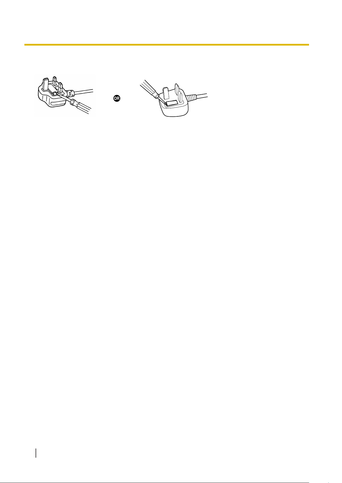
IF THE FITTED MOULDED PLUG IS UNSUITABLE FOR THE AC OUTLET IN YOUR PREMISES, THEN
THE FUSE SHOULD BE REMOVED AND THE PLUG CUT OFF AND DISPOSED OF SAFELY. THERE IS
A DANGER OF SEVERE ELECTRICAL SHOCK IF THE CUT-OFF PLUG IS INSERTED INTO ANY 13
AMP SOCKET.
A mark
, the plug must not be used until a replacement cover is obtained. A replacement
or the BSI mark on the body of the fuse.
WARNING
This appliance must be earthed.
Installation Manual 15
1.3 Precautions
How to replace the fuse: Open the fuse compartment with a screwdriver and replace the fuse and fuse
cover.
For users in Germany only
• Machine Noise Information Ordinance, 3rd GPSGV: The highest sound pressure level is 70 dB (A) or less
according to EN ISO 7779.
• This equipment is not for use at video display work stations according to BildscharbV.
For users in New Zealand only
• This equipment shall not be set to make automatic calls to the Telecom ‘1
• The grant of a Telepermit for any item of terminal equipment indicates only that Telecom has accepted
that the item complies with minimum conditions for connection to its network. It indicates no endorsement
of the product by Telecom, nor does it provide any sort of warranty. Above all, it provides no assurance
that any item will work correctly in all respects with another item of Telepermitted equipment of a different
make or model, nor does it imply that any product is compatible with all of Telecom’s network services.
11’ Emergency Service.
• This equipment is not capable, under all operating conditions, of correct operation at the higher speeds
for which it is designed. Telecom will accept no responsibility should difficulties arise in such
circumstances.
• Some parameters required for compliance with Telecom’s Telepermit requirements are dependent on the
equipment (Server) associated with this modem. In order to operate within the limits for compliance with
Telecom’s Specifications, the associated Server equipment shall be set to ensure that modem calls are
answered between 3 and 30 seconds of receipt of ringing.
• Using the toll services of a company other than Telecom:
If the Server is set up to use the toll services of a company other than Telecom, the telephone numbers
dialled from the Caller Display listings within the Server will be directed through the toll services of the
other company because the telephone numbers include the toll access digit and area code digit. A toll
charge may be incurred. Please check with the toll carrier concerned.
• APPLICABLE ONLY TO TELECOM CUSTOMERS WHO HAVE AUTOMATIC ACCESS TO OTHER
CARRIERS FOR TOLL CALLS
When calling back a number from the Caller ID list, all numbers prefixed with "0 + AREA CODE" will be
automatically forwarded to your toll carrier. This includes numbers in your local calling area. The zero +
area code should either be removed when calling back local numbers, or check with your toll carrier that a
charge will not be levied.
• All persons using this device for recording telephone conversations shall comply with New Zealand law.
This requires that at least one party to the conversation is to be aware that it is being recorded. In
addition, the principles enumerated in the Privacy Act 1993 shall be complied with in respect to the nature
of the personal information collected, the purpose for its collection, how it is used, and what is disclosed
to any other party.
• The SLT ports are not specifically designed for 3-wire-connected equipment. 3-wire-connected equipment
might not respond to incoming ringing when attached to these ports.
16 Installation Manual

For users in Australia only
• No External TRC Terminal is provided due to an Internal Link between PE and TRC.
1.3 Precautions
Installation Manual 17

1.4 Data Security
1.4 Data Security
In order to use the Control Box safely and correctly
Failure to do so may result in:
, the Security Requirements below must be observed.
• Loss, leakage, falsification or theft of user information.
• Illegal use of the Control Box by a third party
.
• Interference or suspension of service caused by a third party.
What is User Information?
User Information is defined as:
1. Information stored on the Storage Memory Card:
System data and error data.
2. Information sent from the Control Box to a PC:
System data.
Requirements
1. The Storage Memory Card contains software for all the processes of the Control Box and all the
customer data.
Therefore, do not allow unauthorised access to prevent data leakage.
2. Always make backups of data stored on the Storage Memory Card.
3. To prevent illegal access from the Internet, activate a Firewall.
4. To avoid unauthorised access and possible abuse of the Control Box, we strongly recommend:
a. Keeping the password secret.
b. Selecting a complex, random password that cannot be easily guessed.
c. Changing your password regularly.
5. Perform the following when sending the Control Box for repair or handing it over to a third party.
a. Make a backup of data stored on the Storage Memory Card.
b. Using a formatter, format the Storage Memory Card so that information cannot be retrieved from
it.
6. To prevent data leakage, render the Storage Memory Card physically unusable before disposal.
7. When user information is sent from the Control Box to a PC, the confidentiality of that information
becomes the responsibility of the customer. Before disposing of the PC, ensure that data cannot be
retrieved from it by formatting the hard disk and/or rendering it physically unusable.
8. When configuring email addresses, make sure all information is entered correctly. Incorrect information
could cause user information to be disclosed to unintended recipients.
9. Note that user information may be deleted or initialised when the product is repaired.
10. Refer all repairs to a trusted Panasonic service centre.
11. Protect user information stored on the computer used to configure the system.
• When user information is stored on a computer, the confidentiality of that information becomes the
responsibility of the installer. Take precautions to prevent the unauthorised use of the computer and
the setup tool used for performing system configuration or maintenance.
• Connect the computer to the network only when performing system configuration or maintenance,
and disconnect the computer from the network as soon as the work is complete.
18 Installation Manual

Section 2
System Outline
This section provides general information on the Control
Box, including the system capacity and specifications.
Installation Manual 19
R1R2R3
1 2
R1R2R3
1 2
Facility staff office Control box
E
B
A
F
I
J
K
L
M
G
H
D
C
N
2.1 Basic System Construction
2.1 Basic System Construction
2.1.1 System Configurations
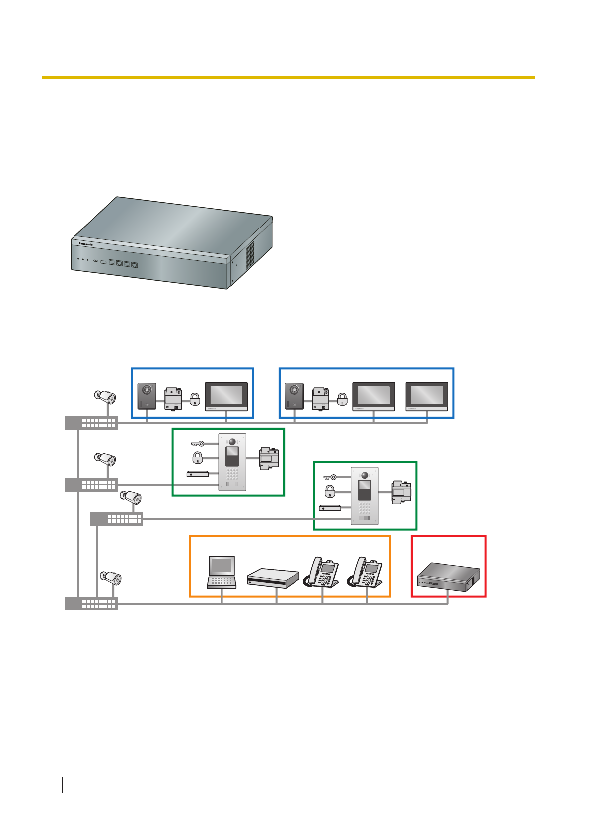
Main Unit
The main unit contains a mother board for controlling the Control Box's operation.
2.1.2 System configuration
Fully expanded system example (up to 2000 SIP devices*1, requires control box)
*1
"SIP devices" include lobby stations, room monitors, door stations, and SIP phones.
20 Installation Manual
Maximum number of devices
A
B
C
D
E
F
G
H
I
J
K
L
M
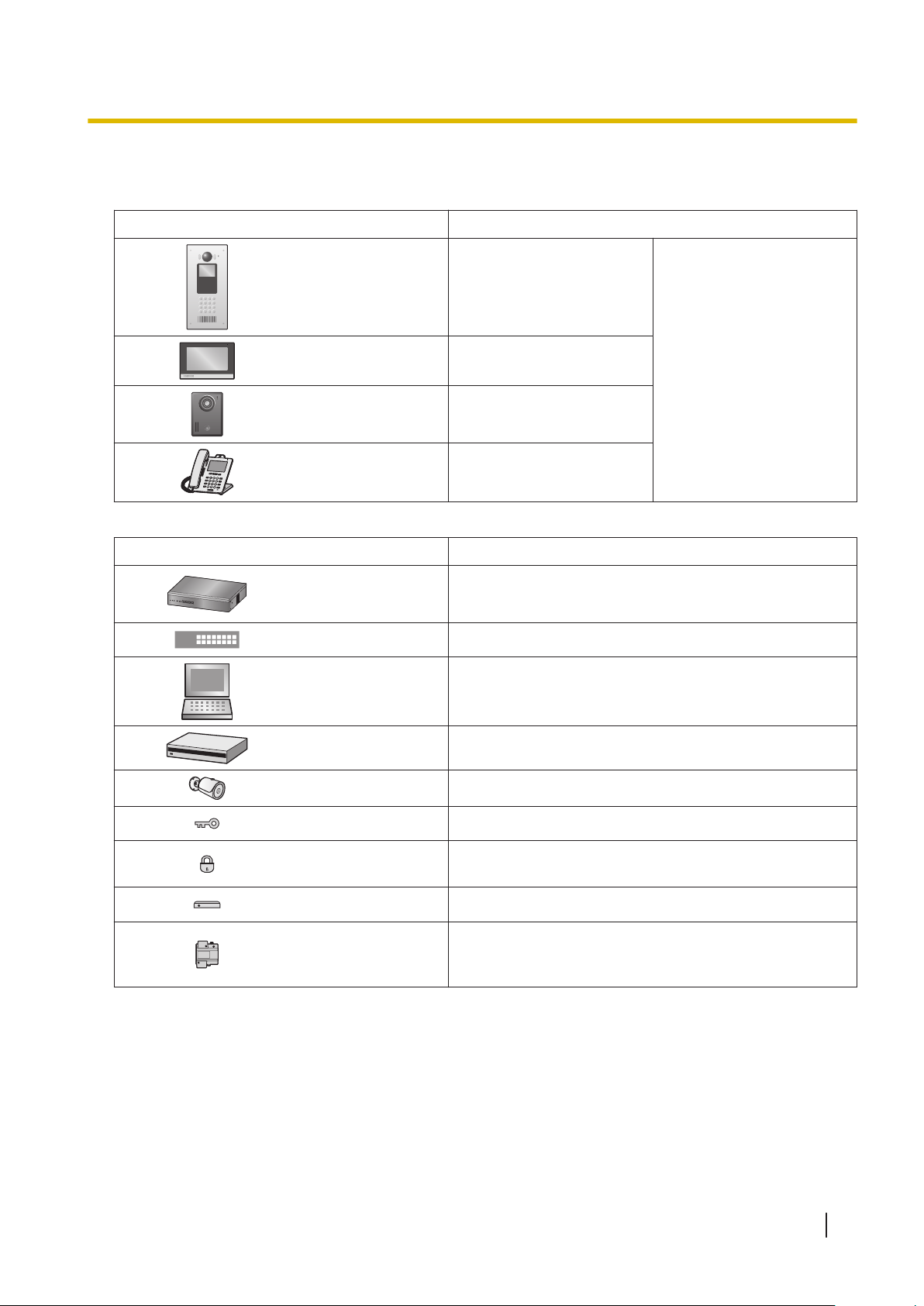
SIP devices
Item Maximum number of devices
2.1.2 System configuration
Other devices
Lobby station 50
Room monitor
Door station
*2
*2
SIP phone 50
*1
5 per room
1 per room
*4
*3
2000
Item Maximum number of devices
Control box 1
Switching hub
Computer (for
programming)
*5
—
—
Network video recorder —
Network camera 500
*6
Access controller 1 per lobby station
Electric lock
1 per lobby station
1 per door station
Open door sensor 1 per lobby station
1 per lobby station
Power supply unit
1 per room monitor
1 per door station
*2
*2
Installation Manual 21
 Loading...