

Panasonic VL-VM701, VL-VM301, VL-VM302, VL-VM101, VL-VM901 Installation And Operating Instructions Manual
...
Installation and Operating Instructions
Video Intercom System — Lobby station/Distributor
Model No. VL-VM series / VL-VM701
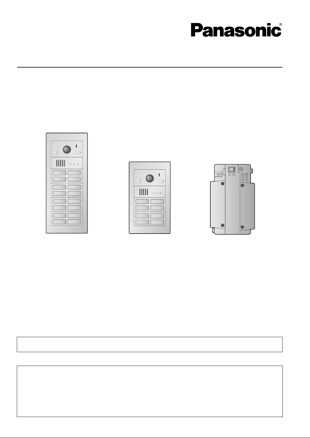
Lobby station
(16 call buttons)
Lobby station
(8 call buttons)
Distributor
(VL-VM701)
*1
Thank you for purchasing a Panasonic product.
Please follow all instructions in this document and save it for future reference.
Carefully
*1 In India, VL-VM701 is not sold and bus wiring is not available.
This system is an auxiliary system; it is not designed to provide complete protection from property loss.
Panasonic
Note to the installer
R This document includes instructions for both installation and operation. See the section titled
R Please read this document carefully, and install the product safely and correctly by following the
R Only use attachments/accessories specified by the manufacturer.
R The installation shall be carried out in accordance with all applicable installation rules.
read the information found in the section titled "2.1 Important safety information" in particular.
will not be held responsible in the event that property loss occurs while this system is in operation.
"4 Installation" for installation instructions.
instructions.

Table of Contents
1. Introduction
1.1 System overview ...........................................3
2. Important Information
2.1 Important safety information ..........................7
2.2 Important safety instructions .........................8
2.3 Privacy and rights of portrait .........................8
2.4 Disclaimer .....................................................8
2.5 Other important information ..........................8
2.6 General information .......................................8
2.7 For India only ................................................9
2.8 For Europe ....................................................9
3. Preparation
3.1 System devices ...........................................10
3.2 Device diagrams .........................................16
3.3 Specifications ..............................................18
4. Installation
4.1 Installation cautions .....................................20
4.2 Installing the power supply unit (sold
separately) ..................................................20
4.3 Installing the lobby station ...........................25
4.4 Installing the extension box (sold
separately) ..................................................34
4.5 Installing the distributor (sold
separately) ..................................................35
4.6 Wiring Connections .....................................36
4.7 DIP switch settings ......................................40
4.8 Distributor POWER and ACCESS
indicators .....................................................43
4.9 Connecting other devices ............................43
4.10 Room name plates ......................................44
5. Basic Operations
5.1 System conditions and limitations ...............45
5.2 Lobby station operations .............................45
6. Other information
6.1 Basic troubleshooting ..................................46
6.2 Cleaning ......................................................47
6.3 Terms and illustrations in this
document ....................................................47
6.4 Trademarks (for France) .............................47
2

1. Introduction
1.1 System overview
This document explains how to install and configure a Video Intercom System for Apartment Complexes comprised
1. . Introduction
of the VL-VM series devices.
Additionally, general information is provided for connecting other devices to the system.
1.1.1 Main features
Easy installation
A flexible system that accommodates up to 32 rooms can be designed by combining call button modules.
–
– The lobby station supports the two main wiring methods (star and bus).
Easy maintenance
– Our unique front-access nameplates are easily changed, even after the lobby station is installed.
3
#16
#15
#14
#13
#4
#3
#2
#1
#32
#31
#30
#29
#20
#19
#18
#17
A
G H
D
B
#4
#3
#2
#1
H
A
D
C
E
B
G
1. Introduction
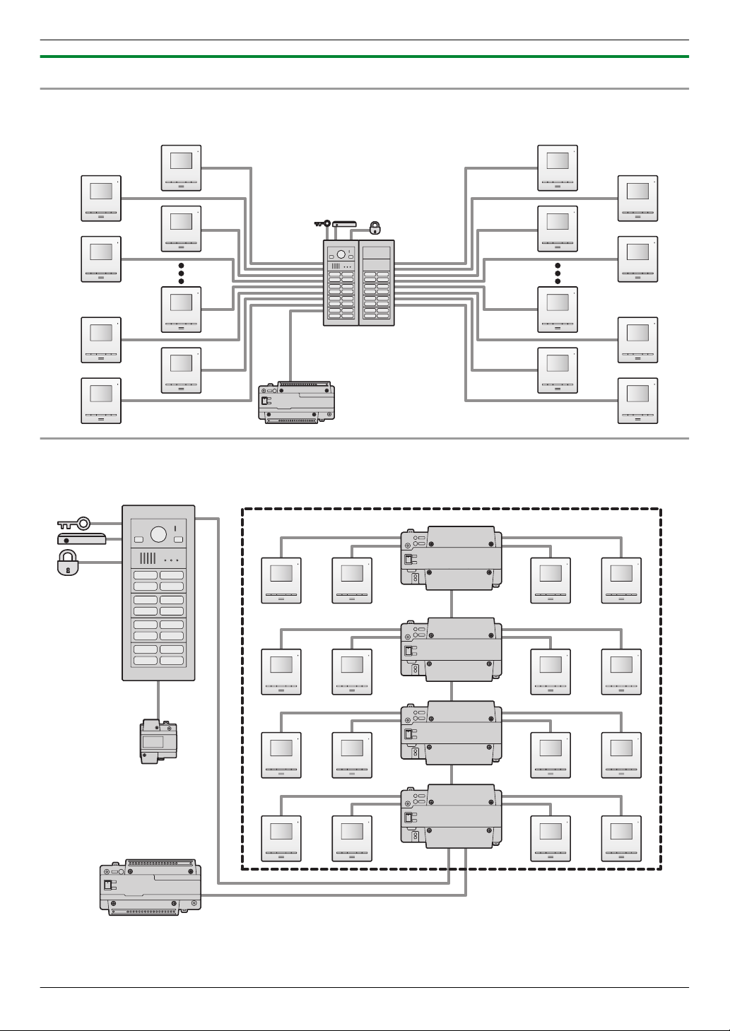
1.1.2 System configuration
Star wiring example
Example: 32 call buttons on the lobby station
Bus wiring example
Example 1: 16 call buttons on the lobby station
4

Bus wiring example
D D
F
#8
#7
#6
#5
#4
#3
#2
#1
E
B
H
A
C
#1 #2 #3 #4 #5 #6
C
G
Example 2: 32 call buttons on the lobby station/6 lobby stations
1. Introduction
System devices
R See page 23 for information about connections for power supply units.
No. Item Star wiring Bus wiring
A Lobby station (VL-VM series) Up to 1 Up to 6
B
C
D Power supply unit (VL-PS2410)
*1
*2
Main monitor
,
Up to 32 (depending on the composition of the lobby station's
modules)
Power supply unit (VL-PS240) The number of required power supply units differs depending on the
number of devices used.
The number of required power supply units differs depending on the
number of devices used.
E Distributor (VL-VM701) – Up to 8
F Extension box (VL-V703) – Up to 1
connection device (example:
K-IN
access controller and/or open
G
Up to 2 Up to 2
door sensor, etc.)
H Electric lock 1 per lobby station 1 per lobby station
*1 See page 18 for specifications and information about supported models.
*2
VL-MV10 and VL-MWD501 support door bells. For VL-MWD501, a sound is played when the door bell is pressed,
but “Doorphone unavailable” is displayed on the screen (this is normal).
5
1. Introduction
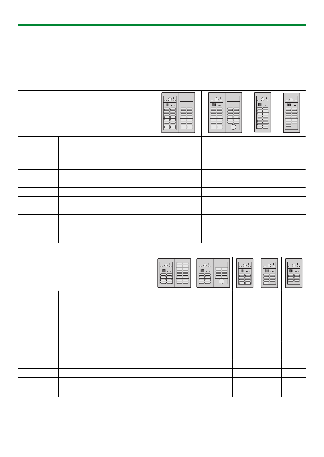
1.1.3 Lobby station components
The lobby station is composed of the following modules according to the number of rooms. See
page 26 for
information about assembly.
Note:
R Regardless of the number of button module combinations, a maximum of 8 button modules can be used in 1 lobby
station.
Large type lobby station example
Module
Model no. Number of call buttons (Unit:
32 28 16 13
pcs.)
VL-VM101 Camera module 1 1 1 1
VL-VM301 1-button module – – – 1
VL-VM302 2-button module – – – –
VL-VM303 3-button module – – – –
VL-VM304 4-button module 8 7 4 3
VL-VM901 Blank panel 2 2 – –
VL-VM801 Extension cable 1 1 – –
VL-VM603 Back box 2 2 1 1
VL-VM503
VL-VM902
*1
Surface mount cover
VIGIK® panel
*1
*2
2 2 1 1
– 1 – –
Small type lobby station example
Module
Model no. Number of room buttons (Unit:
24 16 8 7 6
pcs.)
VL-VM101 Camera module 1 1 1 1 1
VL-VM301 1-button module – – – – –
VL-VM302 2-button module – – – – 1
VL-VM303 3-button module – – – 1 –
VL-VM304 4-button module 6 4 2 1 1
VL-VM901 Blank panel – 1 – – –
VL-VM801 Extension cable 1 1 – – –
VL-VM602 Back box 2 2 1 1 1
VL-VM502
VL-VM902
*1
Surface mount cover
VIGIK panel
*2
*1
2 2 1 1 1
– 1 – – –
*1 The surface mount cover cannot be attached when the lobby station is flush mounted. However, make sure to
use the surface mount cover when the lobby station is surface mounted.
For France
*2
6
2.1 Important safety information
WARNING
CAUTION
To
2. . Important Information
prevent severe injury or loss of life or property, and to
ensure proper and safe operation of your product, read
this section carefully before using the product.
Preventing fire, electric shock and short circuits
R Leave
R For Australia/New Zealand only:
R Use only the power supply unit VL-PS240 or
R Do not place objects on the power cables. Install the
R Do not allow the power cables to be excessively
R Make sure all connections from the power outlet to
R Never touch the power supply unit and power cables
R Do not use the power supply unit for outdoor
R Do not disassemble or modify the product. Refer
R Do not touch the product or the power supply unit
R Never install wiring during a lightning storm.
R Do not connect non-specified devices.
R Do not connect a power cable to a terminal that is not
R When opening holes in walls for installation or wiring,
R Do not make any wiring connections when the power
R Do not install the product and power supply unit in the
installation work to the dealer. Installation
work requires technical knowledge and
experience. Electrical connection work should be
performed by certified personnel only. Failure to
observe this may cause fire, electric shock,
injury, or damage to the product. Consult the
dealer.
VL-PS240 or VL-PS2410 only: Installation must only
be by a registered electrician. Wiring must be
performed according to AS/NZS 3000 wiring rules.
VL-PS2410.
product where no one can step or trip on the power
cables.
pulled, bent or placed under heavy objects.
the power supply unit are secure.
with wet hands.
installations (it is for indoor use only).
servicing to an authorised service centre when
service is required. Disassembling the product or
manipulating the product in a way not described in
the documentation may expose you to dangerous
voltages and other risks.
during an electrical storm. There may be a remote
risk of electric shock from lightning.
specified in this document.
or when securing the power cable, make sure you do
not damage existing wiring and ductwork.
outlet is turned on.
following places:
– Places where the product and power supply unit
may be splashed with water or chemicals
– Places where there is a high concentration of dust
or high humidity
2. Important Information
not push any objects through the openings of the
R Do
product.
R If any of the following conditions occur, disconnect
the power supply unit from the power outlet, and then
refer servicing to an authorised service centre.
– The product emits smoke, an abnormal smell or
makes unusual noise
– The power cables are damaged or frayed
– Metal objects have been dropped inside the
product
R When existing wires are used, it is possible that they
contain AC voltage. Contact an authorised service
centre.
Preventing accidents
R Name plate buttons may become a choking hazard.
Keep name plate buttons out of reach of children. If
you suspect a child has swallowed a name plate
button, seek medical advice immediately.
Preventing accidents, injuries, and property damage
R Do not use the product in unstable areas or areas
prone to strong vibrations. This may cause the
product to fall, resulting in damage to the product or
injury.
R Make sure you turn off the power at the breaker
before performing any wiring work.
R Always connect power cables to the appropriate
connection terminals. Incorrectly connecting the
power cables may damage the power supply unit.
prevent the power cables from disconnecting and
R To
to prevent electric shock, secure the power cable
using the included cable binders and attach the cable
covers.
R Insert the power cables firmly all the way into the
terminals. If the cables are not inserted all the way,
heat may be generated.
R If the wiring passes outdoors, use a conduit and a
surge protector.
R If the wiring passes underground, use a conduit, and
do not make any connections underground.
R Install the product securely adhering to the
instructions in this document to prevent it from falling
off the wall. Avoid installing onto low-strength walls,
such as gypsum board, ALC (autoclaved lightweight
concrete), concrete block, or veneer (less than
18 mm thick) walls.
R The power supply unit is used as the main disconnect
device. Ensure that the power outlet is installed near
the product and is easily accessible.
R Do not put your ear(s) near the speaker, as loud
sounds emitted from the speaker may cause hearing
impairment.
7
2. Important Information
2.2 Important safety instructions
When
using this product, basic safety precautions should
always be followed to reduce the risk of fire, electric
shock, or personal injury.
Use only the power supply unit indicated in this
document.
SAVE THESE INSTRUCTIONS
2.3 Privacy and rights of portrait
When installing or using the product, please take into
consideration the rights of others with regard to privacy.
R It is generally said that
an individual or group to stop information about
themselves from becoming known to people other
than those whom they choose to give the information.
"Rights of portrait" means the right to be safe from
having your own image taken and used
indiscriminately without consent.
R Please observe the legal regulations (data
protection, video surveillance) in your country during
use.
"privacy" means the ability of
2.4 Disclaimer
the maximum extent permitted by law, Panasonic
R To
assumes no responsibility for injuries or property
damage resulting from failures arising out of improper
installation or operation inconsistent with this
document.
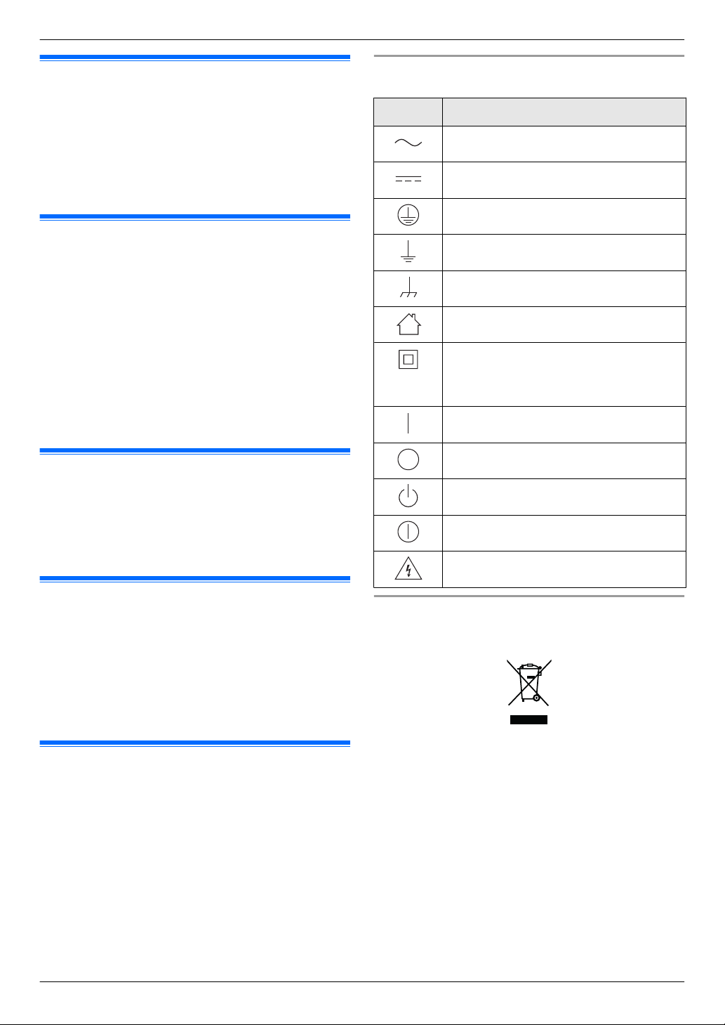
Graphical symbols for use on equipment and their
descriptions
Symbol Explanation
Alternating current (A.C.)
Direct current (D.C.)
Protective earth
Protective bonding earth
Functional earth
For indoor use only
Class P equipment (equipment in which
protection
Double Insulation or Reinforced
Insulation)
"ON" (power)
"OFF" (power)
Stand-by (power)
"ON"/"OFF" (power; push-push)
Caution, risk of electric shock
against electric shock relies on
2.5 Other important information
R When
R If you stop using the product, remove it from the walls
R When power fails, this product cannot be used.
R Panasonic may not be liable for damages due to
you leave the product unused for a long period
of time, unplug it from the power outlet.
to prevent it from falling off.
external factors such as power failures.
2.6 General information
R The available products differ depending on your
region. For more information, please consult
your dealer.
R In the event of problems, you should contact your
equipment supplier in the first instance.
R After removing the product and any included items
from the packaging, store, dispose, or recycle the
packaging as necessary. Note that certain types of
packaging may be a suffocation or choking hazard.
8
Disposal of Old Equipment (Only
and countries with recycling systems)
A
This symbol (A) on the products, packaging, and/or
accompanying documents means that used electrical
and electronic products must not be mixed with general
household waste.
For proper treatment, recovery and recycling of old
products, please take them to applicable collection
points in accordance with your national legislation.
By disposing of them correctly, you will help to save
valuable resources and prevent any potential negative
effects on human health and the environment.
For more information about collection and recycling,
please contact your local municipality.
Penalties
waste, in accordance with national legislation.
may be applicable for incorrect disposal of this
for European Union

2. Important Information
For business users in the European Union
If
you wish to discard electrical and electronic equipment,
please contact your dealer or supplier for further
information.
Information on Disposal in other Countries outside
the European Union
This symbol (A) is only valid in the European Union. If
you wish to discard this product, please contact your
local authorities or dealer and ask for the correct method
of disposal.
2.7 For India only
Declaration of Conformity with the requirements of
the E-Waste (Management) Rules
Product is in conformity with the requirements of the
The
reduction of hazardous substances of the E-Waste
Rules.
The content of hazardous substance with the exemption
of the applications listed in SCHEDULE II of the E-Waste
Rules:
1. Lead (Pb) – not over 0.1% by weight;
2. Cadmium (Cd) – not over 0.01% by weight;
3. Mercury (Hg) – not over 0.1% by weight;
4. Hexavalent chromium (Cr6+) – not over 0.1% by
weight;
5. Polybrominated biphenyls (PBBs) – not over 0.1% by
weight;
6. Polybrominated diphenyl ethers (PBDEs) – not over
0.1% by weight.
Panasonic Testing Centre
Panasonic Marketing Europe GmbH
Winsbergring 15, 22525 Hamburg, Germany
http://www.ptc.panasonic.eu/doc
Ecodesign information
Ecodesign information under EU Regulation
No. 1275/2008 amended by (EU) Regulation
No. 801/2013. From 1 January 2015.
Please visit here:
http://www.ptc.panasonic.eu/erp
Click [Downloads] ® [Energy related products
information (Public)]
Power consumption in networked standby and guidance
are mentioned in the web site above.
This device is classified as a HiNA device (networked
equipment with high network availability), according to
Ecodesign requirements.
(EC)
Disposal information
For the purpose of recycling to facilitate effective
utilization of resources, please return this product to a
nearby authorized collection centre, registered
dismantler
disposing of this product.
Please see the Panasonic website for further information
on collection centres, etc., or call the toll-free number
below.
Website:
http://www.panasonic.com/in/corporate/sustainability/
panasonic-india-i-recycle-program.html
Service helpline: 1800 103 1333 or 1800 108 1333
or recycler, or Panasonic service centre when
2.8 For Europe
For information of Compliance with EU relevant
Regulatory Directives,
Contact to Authorised Representative:
9
3. Preparation
3.1 System devices
The following modules or devices are sold separately.
3. . Preparation
Please contact your nearest Panasonic dealer for sales
information.
Compatible system devices (as of July 2018)
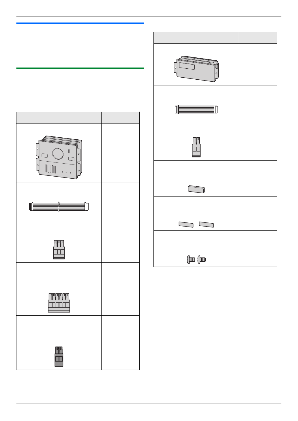
3.1.1 Lobby station
VL-VM301
Item Quantity
1-button module
1
The lobby station is composed of combinations of
modules. The following items are included with the
modules.
VL-VM101
Item Quantity
Camera module
Flat cable
Used to connect modules.
3-pin terminal block
Used to connect wires to the
K-OUT connection terminals.
1
1
1
Flat cable
Used to connect modules.
2-pin terminal block
Used when using star wiring.
Spare button
Used as a spare when replacing
name plates.
Name sheet
Used as a spare when replacing
name plates.
Screw (2 mm ´ 3 mm)
Used to prevent the removal of
name plates.
1
1
1
2
2
6-pin terminal block
Used to connect wires to the K-IN
(4 pins) and connection terminals
when using bus wiring
DC terminal block
Used to connect wires from the
power supply unit to the lobby
station.
(2 pins).
10
1
1
3. Preparation
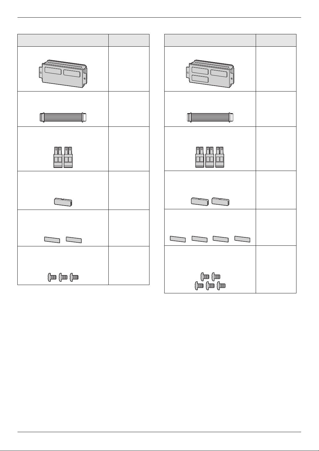
VL-VM302
Item Quantity
2-button module
Flat cable
Used to connect modules.
2-pin terminal block
Used when using star wiring.
Spare button
Used as a spare when replacing
name plates.
VL-VM303
Item Quantity
1
1
2
1
3-button module
Flat cable
Used to connect modules.
2-pin terminal block
Used when using star wiring.
Spare button
Used as a spare when replacing
name plates.
1
1
3
2
Name sheet
Used as a spare when replacing
name plates.
Screw (2 mm ´ 3 mm)
Used to prevent the removal of
name plates.
2
3
Name sheet
Used as a spare when replacing
name plates.
Screw (2 mm ´ 3 mm)
Used to prevent the removal of
name plates.
4
5
11
3. Preparation
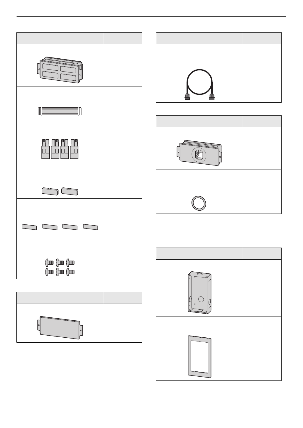
VL-VM304
Item Quantity
4-button module
Flat cable
Used to connect modules.
2-pin terminal block
Used when using star wiring.
Spare button
Used to prevent the removal of
name plates.
VL-VM801
Item Quantity
1
1
4
2
Extension cable
Used to connect 2 frames of a
lobby station together.
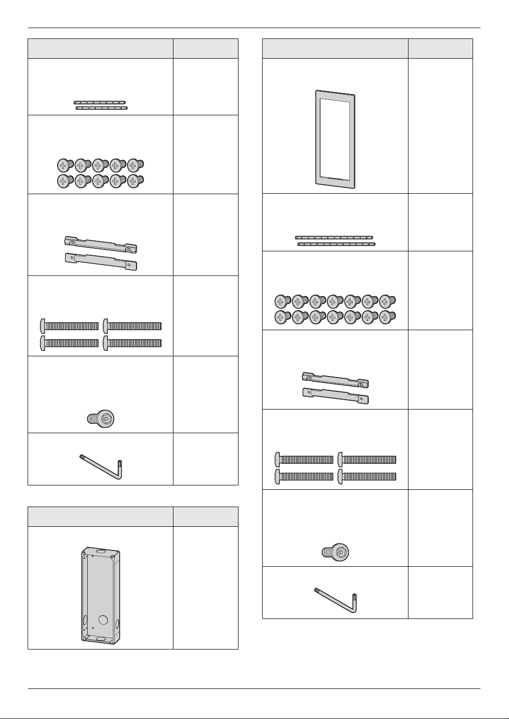
VL-VM902 (for France)
Item Quantity
VIGIK panel 1
Waterproof rubber
Used when attaching the VIGIK
reader.
*1
1
1
Name sheet
Used as a spare when replacing
name plates.
Screw (2 mm ´ 3 mm)
Used to prevent the removal of
name plates.
VL-VM901
Item Quantity
Blank panel
4
*1 The
6
1
VL-VM602 (small type)
waterproof rubber is fixed to the panel with tape.
Remove the waterproof rubber when attaching the
panel.
Item Quantity
Back box
Frame
Used to assemble modules.
1
1
12
3. Preparation
Item Quantity
Side plate
Used to secure and attach the left
and right sides of modules.
Screw (3 mm ´ 5 mm)
Used to attach modules to side
plates.
Upper/lower plate
Used to attach the back box to a
wall.
Screw (4 mm ´ 25 mm)
Used to secure the upper and
lower plates.
2
10
2
4
Item Quantity
Frame
Used to assemble modules.
Side plate
Used to secure and attach the left
and right sides of modules.
Screw (3 mm ´ 5 mm)
Used to attach modules to side
plates.
1
2
14
Hexalobular screw
(3 mm ´ 12 mm)
Used
to secure the lobby station to
the back box.
Hexalobular wrench
VL-VM603 (large type)
Item Quantity
Back box
Upper/lower plate
Used to attach the back box to a
1
1
1
wall.
Screw (4 mm ´ 25 mm)
Used to secure the upper and
lower plates.
Hexalobular screw
(3 mm ´ 12 mm)
Used
to secure the lobby station to
the back box.
Hexalobular wrench 1
2
4
1
13
3. Preparation
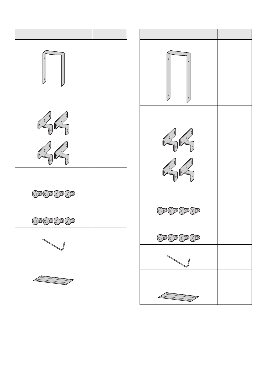
VL-VM502 (small type)
Item Quantity
Surface mount cover
Bracket
Used to attach the surface mount
cover to the back box.
Hex screw (3 mm ´ 5 mm)
Used to attach the bracket to the
back box.
Used to attach the surface mount
cover to the bracket.
VL-VM503 (large type)
Item Quantity
1
4
8
Surface mount cover
Bracket
Used to attach the surface mount
cover to the back box.
Hex screw (3 mm ´ 5 mm)
Used to attach the bracket to the
back box.
1
4
8
Hex wrench 1
Dustproof sheet
Used to attach the sheet to the
bottom of the back box.
14
Used to attach the surface mount
cover to the bracket.
Hex wrench 1
1
Dustproof sheet
Used to attach the sheet to the
bottom of the back box.
1
3. Preparation
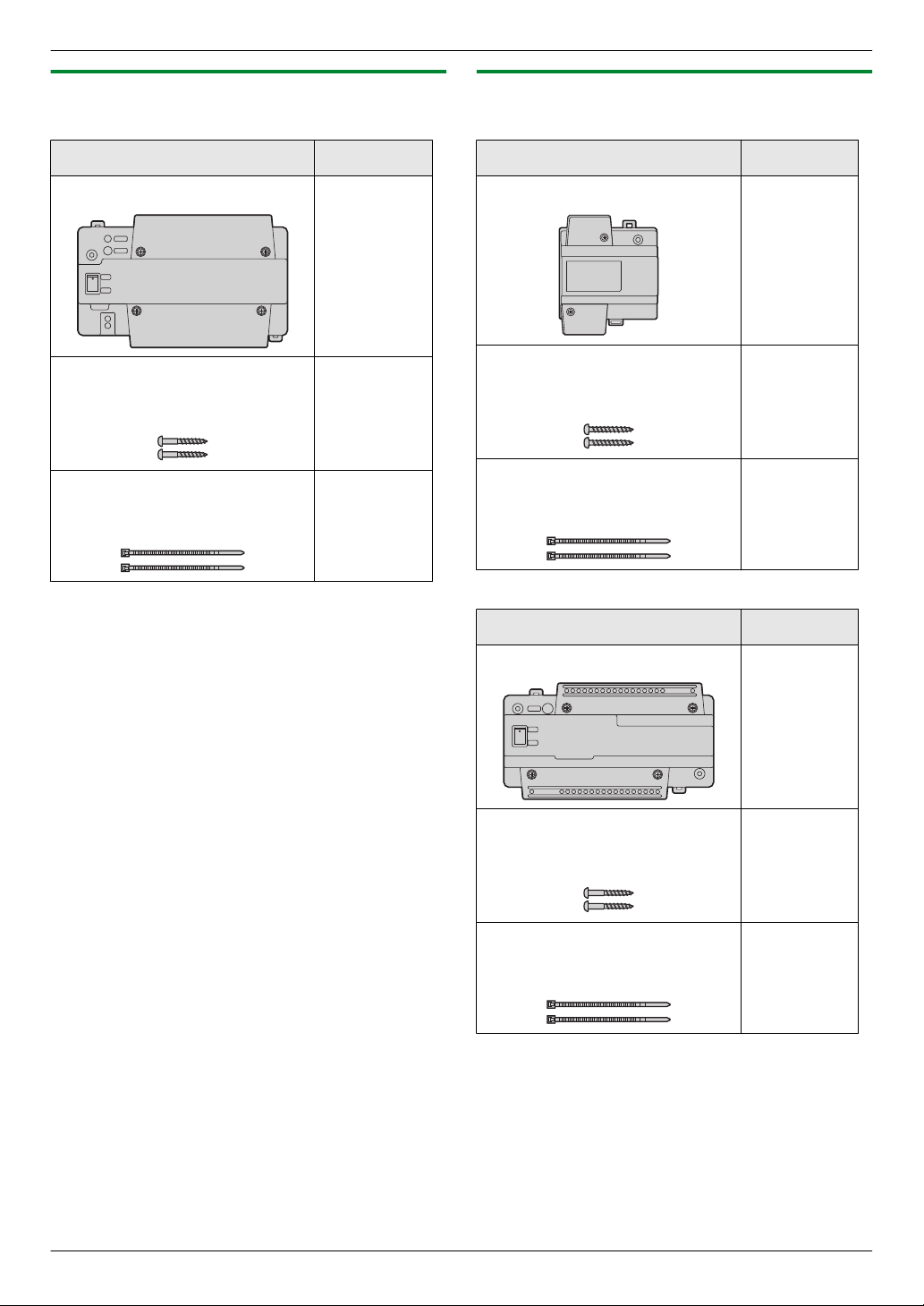
3.1.2 Distributor
VL-VM701 (bus wiring)
Item Quantity
Distributor 1
Screw (3.8 mm ´ 20 mm)
Used to secure the distributor to
the wall.
Cable binder
Used to secure the connected
wires.
3.1.3 Power supply unit
VL-PS240 (0.6 A type)
Item Quantity
Power supply unit 1
2
2
Screw (4 mm ´ 40 mm)
Used to secure the power supply
unit to the wall.
Cable binder
Used to secure the AC and DC
wires.
VL-PS2410 (2.5 A type)
2
2
Item Quantity
Power supply unit 1
Screw (3.8 mm ´ 20 mm)
Used to secure the power supply
unit to the wall.
Cable binder
Used to secure the AC and DC
wires.
2
2
15
 Loading...