

Page 1
Getting Started
DECT Repeater
Model No. VL-FKD2
Table of Contents
Introduction 2
Accessory information 3
For your safety 4
Important safety instructions 5
For best performance 5
Other important information 5
Controls 7
Installation/Registering the repeater to the
main monitor
8
Wall mounting 9
Troubleshooting 10
Cleaning 10
Specifications 10
General information 11
Thank you for purchasing a Panasonic product.
Please read this manual before using the product and save it for future reference.
English
Polski Română
Magyar
Page 2
Introduction
This product is an additional product designed to be used with the following Panasonic Video Intercom
Systems.
– VL-SWD501/VL-SWD501U (Main monitor station: VL-MWD501)
(The corresponding models are subject to change without notice.)
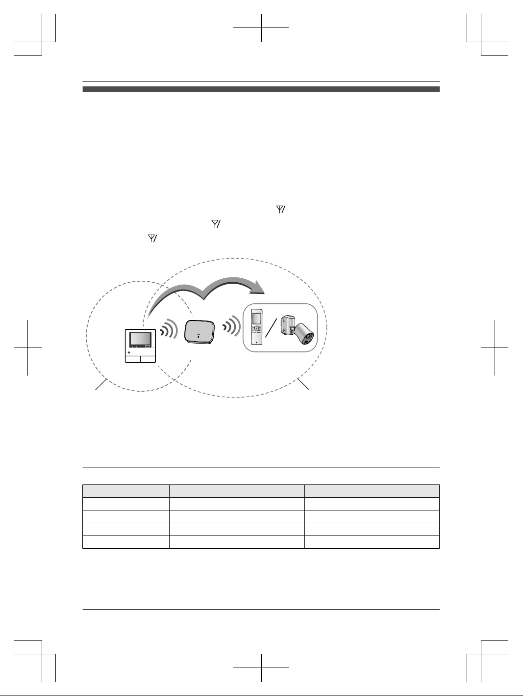
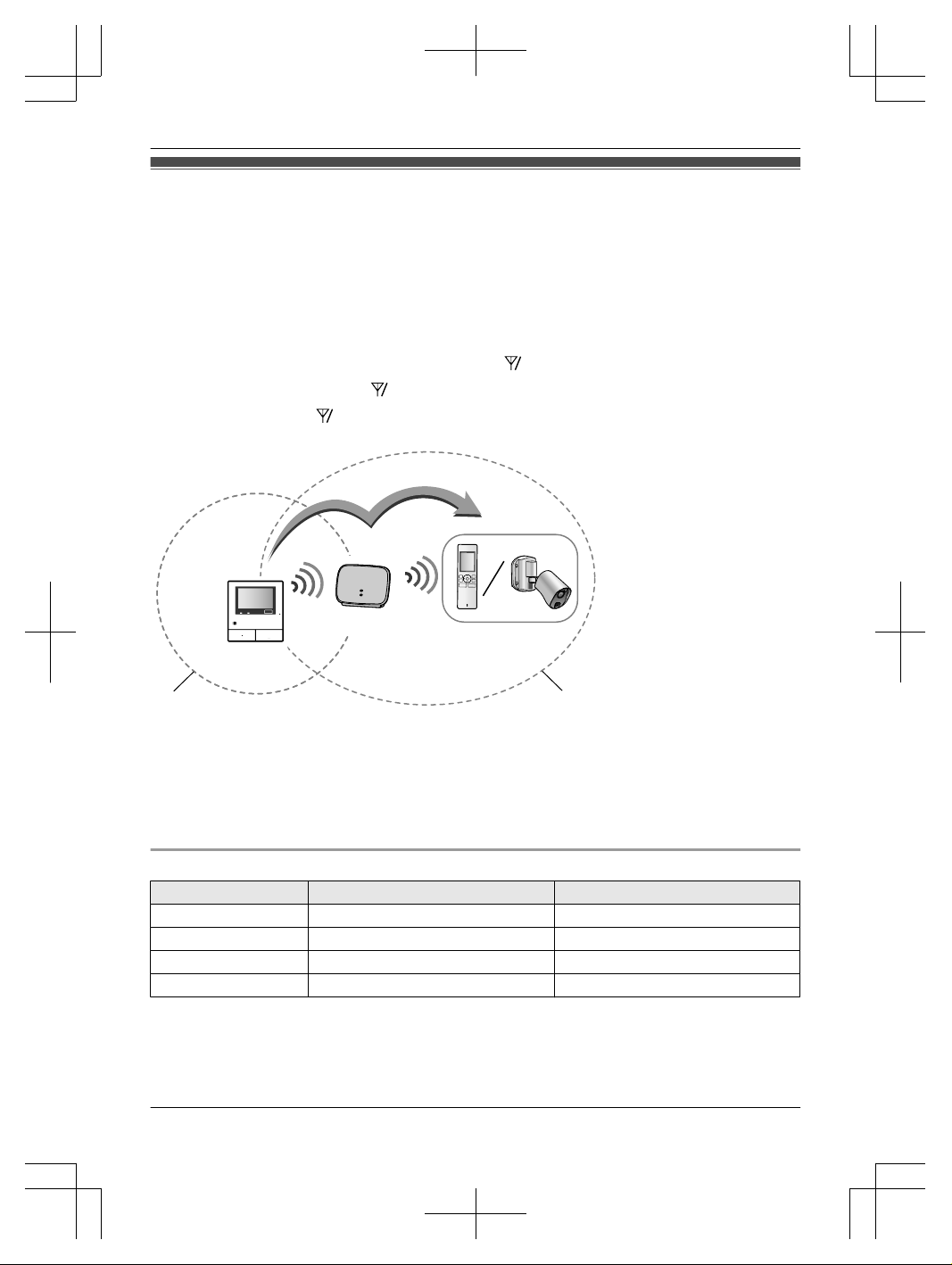
R By installing this product, you can extend the range of your Video Intercom System to include areas
where reception was previously not available.
The product extends the range in all directions, allowing several floors to be covered.
R You must register this product with your Video Intercom System before it can be used.
R Keep an appropriate distance from the main monitor to maximise the range of your Video Intercom
System. Find the appropriate location by checking the ID indicator after registering this product with
your Video Intercom System. If the ID indicator lights red or orange, re-position this product in a
place where the ID indicator lights green.
E
A
B
C
D
A Main monitor
B Repeater
C Device you want to
connect to (sub monitor or
camera)
D Main monitor range
E Repeater range
R When used with the Video Intercom System VL-SWD501 series, a maximum of 2 repeaters can be
used. Because the number of repeaters that can be used may differ depending on the Video Intercom
System series used, see the Operating Instructions of the Video Intercom System for more information.
R The illustrations in the supplied manual(s) may vary slightly from the actual product.
Product names used in this manual
Model No. Product name Name in this manual
VL-FKD2 DECT repeater Repeater
VL-MWD501 Main monitor station Main monitor
VL-WD613 Wireless monitor station Sub monitor
VL-WD812 Wireless sensor camera Camera
R In this manual, the suffix of each model number (e.g., the "FX" in "VL-SWD501FX") is omitted unless
necessary.
2
Page 3
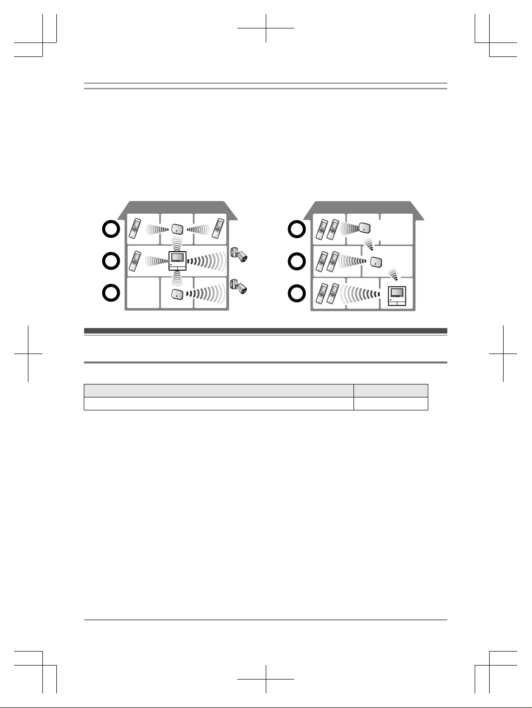
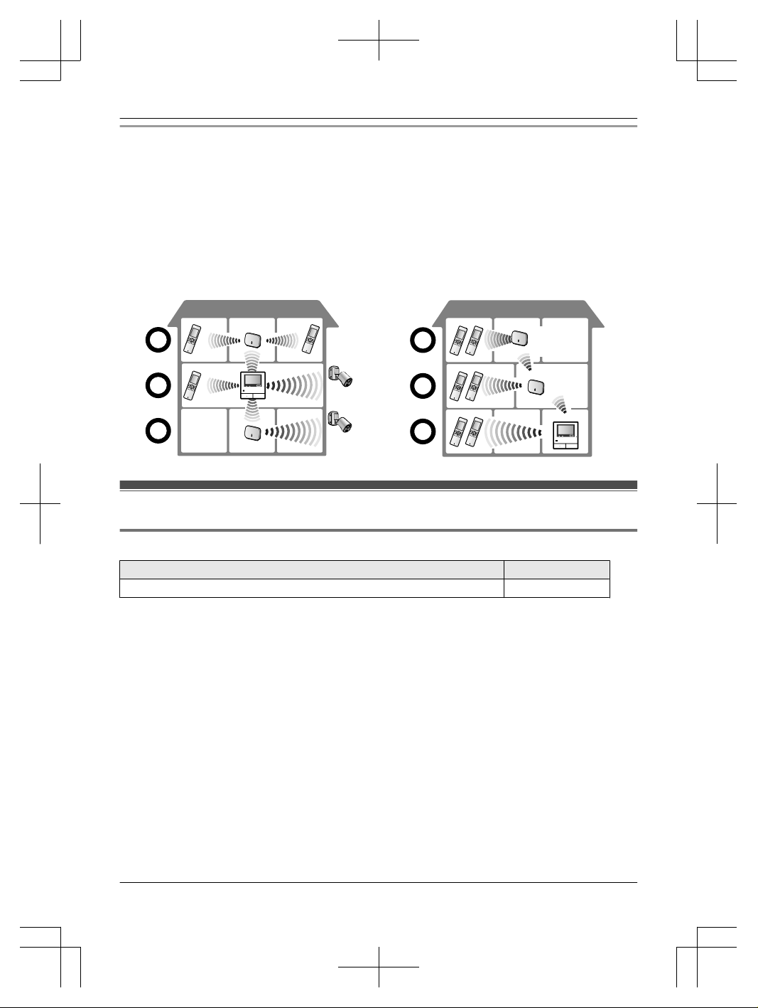
Signal range and repeater installation example
n Using each repeater connected separately
This extends signals away from the main monitor.
Because signals are sent through the main
monitor, different types of devices can be
connected to each repeater. (For example, sub
monitors can be connected to one repeater and
cameras can be connected to another.) This is
useful when you want to connect to different types
of devices over shorter distances.
n Using 2 repeaters connected together
This extends the signal away from the main
monitor by sending signals directly between
repeaters. Because the signals are sent between
repeaters, the same type of device must be
connected to both repeaters (all sub monitors or
all cameras). This is useful when you want to
connect to the same type of devices over long
distances.
Accessory information
Supplied accessories
Accessory item Quantity
AC adaptor/PQLV219CE 1
Note:
R You will need the following additional items (locally procured) to install the product on the wall.
– Screws x 2 (for wall mounting):
Prepare the screws according to the material, structure, strength and other factors of the mounting
area and the total weight of objects to be mounted.
3
Page 4
For your safety
To prevent severe injury and loss of life/property,
read this section carefully before using the product
to ensure proper and safe operation of your
product.
WARNING
Preventing fire and electric shock
R Use only the power source marked on the
product. If you are not sure of the type of power
supplied to your home, consult your dealer or
local power company.
R Use only the specified AC adaptor.
R Do not attempt to disassemble or modify this
product. Contact an authorised service centre
for repairs.
R Never touch the AC adaptor with wet hands.
R Do not touch the AC adaptor during an electrical
storm.
R Do not perform any actions (such as fabricating,
twisting, stretching, bundling, forcibly bending,
damaging, altering, exposing to heat sources, or
placing heavy objects on the AC adaptor) that
may damage the AC adaptor. Using the product
with a damaged AC adaptor may cause electric
shock, short circuits, or fire. Contact an
authorised service centre for repairs.
R Do not overload the power outlet above the
specified levels. Overloading by having many
connections on one power outlet may cause
heat generation, resulting in a fire.
R Never put metal objects inside the product.
Never spill any liquid on the product.
If metal objects enter the product or the product
becomes wet, unplug the product from the
power outlet and contact an authorised service
centre.
R Do not use a microwave oven or other devices,
such as electromagnetic cookers to speed up
the drying process of any parts of the product.
R Completely insert the AC adaptor into the power
outlet. Failure to do so may cause electric shock
and/or excessive heat resulting in a fire. Do not
use damaged AC adaptors or power outlets.
R Regularly remove any dust, etc., from the AC
adaptor by unplugging it from the power outlet,
then wiping it with a dry cloth. Accumulated dust
may cause an insulation defect from moisture,
etc., resulting in a fire.
R Unplug the product from the power outlet if the
product emits smoke, an abnormal smell or
makes unusual noise, or if the product has been
dropped or physically damaged. These
conditions can cause fire or electric shock.
Confirm that smoke has stopped emitting and
contact an authorised service centre.
R Hold the main body (not the metal parts) of the
AC adaptor when unplugging it. Unplugging the
AC adaptor while holding its cord or the cord’s
plugs may result in fire, electric shock, or injury.
Preventing accidents
R Do not use the product in health care facilities if
any regulations posted in the area instruct you
not to do so. Hospitals or health care facilities
may be using equipment that could be sensitive
to external RF (radio frequency) energy.
R Do not install or use this product near
automatically controlled devices such as
automatic doors and fire alarms. Radio waves
emitted from this product may cause such
devices to malfunction, resulting in an accident.
R Consult the manufacturer of any personal
medical devices, such as pacemakers or
hearing aids, to determine if they are adequately
shielded from external RF (radio frequency)
energy. (The product operates in the frequency
range of 1.88 GHz to 1.90 GHz, and the RF
transmission power is 250 mW (max.).)
CAUTION
Preventing fire and electric shock
R Do not use the product in areas that are
exposed to rain, moisture, steam, or oily smoke,
or areas that have excessive dust.
Preventing accidents, injuries, and property
damage
R Do not use the product in unstable areas or
areas prone to strong vibrations.
When mounting the product to a wall, install the
product securely adhering to the instructions in
this manual to prevent it from falling off the wall.
Avoid installing onto low-strength walls, such as
gypsum board, ALC (autoclaved lightweight
concrete), concrete block, or veneer (less than
18 mm thick) walls. These may cause the
product to fall, resulting in damage to the
product or injury.
4
Page 5
Important safety instructions
When using your product, basic safety precautions
should always be followed to reduce the risk of
fire, electric shock, and injury to persons, including
the following:
1. Do not use this product near water for
example, near a bathtub, washbowl, kitchen
sink, or laundry tub, in a wet basement or near
a swimming pool.
2. Use only the AC adaptor indicated in this
manual.
SAVE THESE INSTRUCTIONS
For best performance
Location/avoiding noise
The repeater and other compatible Panasonic
units use radio waves to communicate with each
other. (The product operates in the frequency
range of 1.88 GHz to 1.90 GHz, and the RF
transmission power is 250 mW (max.).)
R Install the repeater within the main monitor
range of the Video Intercom System in an
indoor environment. We recommend installing
the repeater in a raised position (such as on a
wall).
R For maximum coverage (approx. 100 m) and
noise-free communications, install your repeater:
– at a convenient, high, and central location
with no obstructions between the sub monitor
(or camera) and repeater in an indoor
environment.
– away from electronic appliances such as TVs,
radios, personal computers, wireless devices,
or digital cordless phones.
– facing away from radio frequency
transmitters, such as external antennas of
mobile phone stations. (Avoid installing the
repeater near a window.)
R Coverage and voice quality depends on the
local environmental conditions.
R If the reception for a repeater location is not
satisfactory, move the repeater to another
location for better reception.
Environment
R Keep the product away from electrical noise
generating devices, such as fluorescent lamps
and motors.
R The product should not be exposed to direct
sunlight.
R Do not place heavy objects on top of the
product.
R When you leave the product unused for a long
period of time, unplug the product from the
power outlet.
R The product should be kept away from heat
sources such as radiators, cookers, etc. It
should not be placed in rooms where the
temperature is less than 0 °C or greater than
40 °C. Damp basements should also be
avoided.
R Do not install the product in locations that are
suspect to sudden changes in temperature.
Failure to do so may cause condensation to
form on the product causing malfunction.
R Even when the repeater and sub monitor (or
camera) are used within 100 m of each other,
obstructions can cause weak signals, noise,
interrupted transmissions, distorted images and
slow image refresh rates. Obstructions can
include:
– Metal doors or metal shutters.
– Heat insulation including aluminium foil.
– Concrete walls or walls made of galvanized
iron sheet.
– If the sub monitor is being used in a different
building, or a different part of the house, i.e. a
different floor to the where the main monitor
has been installed.
– Many walls.
– Double insulated glass windows.
R Operating the product near electrical appliances
may cause interference. Move away from the
electrical appliances.
Other important information
R The AC adaptor is used as the main disconnect
device. Ensure that the power outlet is installed
near the product and is easily accessible.
Information for Users on Collection and
Disposal of Old Equipment and used Batteries
A B C
5
Page 6
These symbols (A, B, C) on the products,
packaging, and/or accompanying documents
mean that used electrical and electronic products
and batteries should not be mixed with general
household waste.
For proper treatment, recovery and recycling of old
products and used batteries, please take them to
applicable collection points, in accordance with
your national legislation and the Directives
2002/96/EC and 2006/66/EC.
By disposing of these products and batteries
correctly, you will help to save valuable resources
and prevent any potential negative effects on
human health and the environment which could
otherwise arise from inappropriate waste handling.
For more information about collection and
recycling of old products and batteries, please
contact your local municipality, your waste
disposal service or the point of sale where you
purchased the items.
Penalties may be applicable for incorrect disposal
of this waste, in accordance with national
legislation.
For business users in the European Union
If you wish to discard electrical and electronic
equipment, please contact your dealer or supplier
for further information.
Information on Disposal in other Countries
outside the European Union
These symbols (A, B, C) are only valid in the
European Union. If you wish to discard these
items, please contact your local authorities or
dealer and ask for the correct method of disposal.
Note for the battery symbol
This symbol (B) might be used in combination
with a chemical symbol (C). In this case it
complies with the requirement set by the Directive
for the chemical involved.
Others
R It is prohibited to disassemble or modify this
product. Contact the dealer where you
purchased this product for repair.
R When power fails, this product cannot be used.
6
Page 7
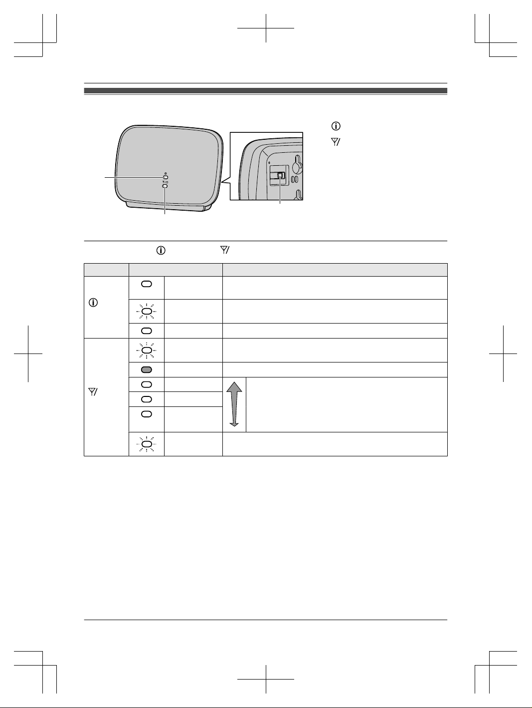
Controls
A
B
C
A
indicator
B
ID
indicator
C PROGRAM
Understanding the indicator and ID indicator
Indicator Light status Meaning
indicator
Lit green Registration with the main monitor is complete and the
repeater can send signals.
Flashing
green
Signals are being sent.
Lit orange Signals are not being sent.
ID
indicator
Flashing
green
Currently registering to the main monitor.
Off Not registered to the main monitor.
Lit green
Strong
Indicates the signal level of the main
monitor.
R Determine the installation location of
the repeater by checking the signal
level shown with the indicator.
Lit orange
Lit red
Weak
Flashing red Signals do not reach the repeater and it should not be installed
in this location. (Out of range.)
7
Page 8
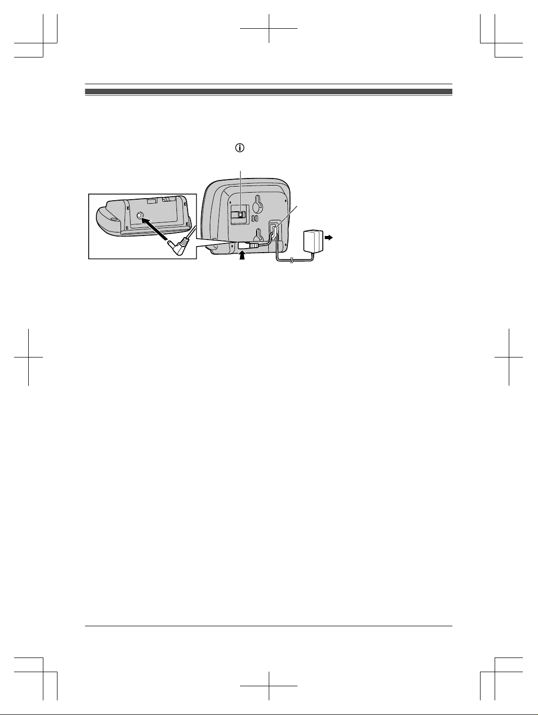
Installation/Registering the repeater to the main monitor
1 Repeater: Connect the AC adaptor, and plug the AC adaptor into a power outlet.
R Use only the supplied Panasonic AC adaptor (® page 3).
R When the repeater is turned on, the indicator lights in orange.
A
B
C
*1
A PROGRAM B Hook C 100-240 V AC, 50/60 Hz
*1 Press plug firmly.
2 Main monitor: Perform the registration operations for the repeater. (® Operating Instructions of the
Video Intercom System)
R The next step must be completed within 120 seconds.
3 Repeater: Press PROGRAM (A) for about 3 seconds.
R If the indicators do not light green, re-position the repeater in a place where the indicators light
green.
Note:
R The AC adaptor must remain connected at all times. (It is normal for the adaptor to feel warm during
use.)
R The AC adaptor should be connected to a vertically oriented or floor-mounted AC outlet. Do not
connect the AC adaptor to a ceiling-mounted AC outlet, as the weight of the adaptor may cause it to
become disconnected.
8
Page 9
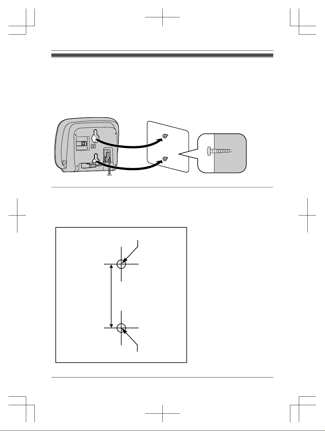
Wall mounting
Make sure that the wall is strong enough to support the weight of the repeater.
1 Place the reference for wall mounting on the wall to mark the 2 screw positions.
2 Install the 2 screws (locally procured) into the wall.
R Make sure that the screw heads are at the same distance from the wall.
R Install the screws perpendicular to the wall.
3 Hook the repeater on the screw heads.
Reference for wall mounting
Print the following guide and use it as a reference for wall mounting.
R Make sure to set the print size to correspond with the size of pages in this manual. If the dimensions of
the printed paper are not exactly the same as the dimensions of this guide, use the measurements
indicated in the guide.
A
A
B
A Install screws in these
positions.
B 37 mm
9
Page 10
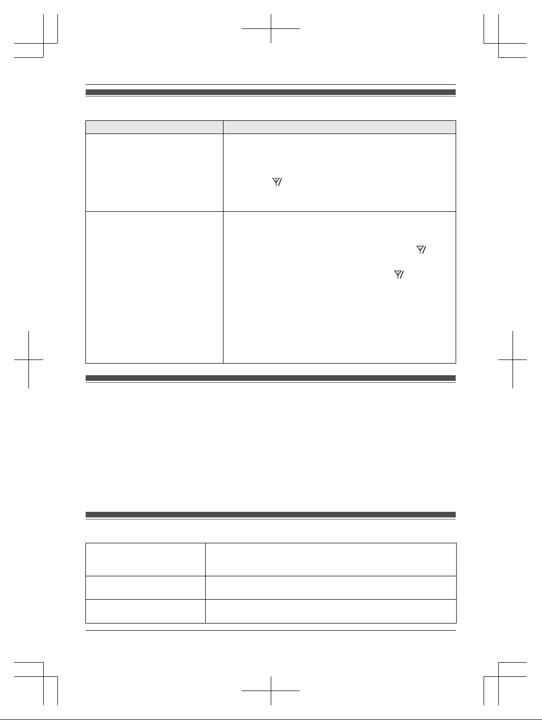
Troubleshooting
Problem Cause/solution
The repeater does not work. R When the indicators do not light, the AC adaptor is not
connected properly. Check the connections.
R When the indicators do not light green, move the repeater
closer to the main monitor.
R When the ID indicator does not light, the registration with
main monitor has not completed successfully. Re-register the
repeater again.
The transmission condition (for
images and sound) of the sub
monitor or camera does not improve
even when a repeater is installed.
R The sub monitor or camera is too far from the repeater.
→Install the sub monitor or camera within signal range of the
repeater.
R The repeater is too far from the main monitor. (The
ID
indicator is lit or flashing in red.)
→Install the repeater in a location where the ID indicator
is stable and lit in green or orange.
R The repeater is too close to the main monitor.
→When the repeater is too close to the main monitor, the
sub monitor or camera only receive signals from the main
monitor, thus making the repeater ineffective. Install the
repeater in a location where the sub monitor or camera are
used, and is as far away from the main monitor as possible
while still staying within signal range of the main monitor.
Cleaning
Wipe the product with a soft, dry cloth.
For excessive dirt, wipe the product with a slightly damp cloth.
Important:
R Do not use any cleaning products that contain alcohol, polish powder, powder soap, benzine, thinner,
wax, petroleum, or boiling water. Also do not spray the product with insecticide, glass cleaner, or hair
spray. This may cause a change in colour or quality of the product.
Cleaning the AC adaptor:
For safety, disconnect the AC adaptor from the power outlet before cleaning.
Specifications
Power source AC adaptor (PQLV219CE)
Input: 100-240 V AC, 0.1 A, 50/60 Hz
Output: 6.5 V DC, 0.5 A
Power consumption During standby: approx. 1.5 W
During operation: approx. 2.3 W (when transmitting)
Dimensions (mm) (height ´
width ´ depth)
Approx. 82´111´39
10
Page 11
Mass (weight) Approx. 88 g (excluding the AC adaptor)
Operating environment Ambient temperature: approx. 0 °C to +40 °C
Relative humidity (non-condensing): up to 90 %
Frequency range 1.88 GHz to 1.90 GHz
Transmitting range Approx. 100 m (line-of-sight distance from the main monitor)
Note:
R Design and specifications are subject to change without notice.
R Names, company names, product names, software names, and logos mentioned in this manual are
trademarks or registered trademarks of the companies concerned.
General information
R In the event of problems, you should contact your equipment supplier in the first instance.
Declaration of Conformity:
R Panasonic System Networks Co., Ltd. declares that this equipment (VL-FKD2FX) is in compliance with
the essential requirements and other relevant provisions of Radio & Telecommunications Terminal
Equipment (R&TTE) Directive 1999/5/EC.
Declarations of Conformity for the relevant Panasonic products described in this manual are available
for download by visiting:
http://www.ptc.panasonic.eu
Contact to Authorised Representative:
Panasonic Testing Centre
Panasonic Marketing Europe GmbH
Winsbergring 15, 22525 Hamburg, Germany
Ecodesign information
Ecodesign information under EU Regulation (EC) No. 1275/2008 amended by (EU) Regulation No.
801/2013. From 1 January 2015.
Please visit here: www.ptc.panasonic.eu
Click [Downloads]
® Energy related products information (Public)
Power consumption in networked standby and guidance are mentioned in the web site above.
For your future reference
We recommend keeping a record of the following information to assist with any repair under warranty.
Serial No. Date of purchase
(found on the rear of the product)
Name and address of dealer
Attach your purchase receipt here.
11
Page 12
Notes
12
Page 13
Wprowadzenie
Wzmacniacz sygnału DECT
Model VL-FKD2
Spis treści
Wprowadzenie 2
Informacje na temat akcesoriów 3
Bezpieczeństwo użytkownika 4
Ważne instrukcje dotyczące bezpieczeństwa 5
Jak uzyskać najlepszą wydajność 5
Inne ważne informacje 6
Sterowanie 7
Montaż/rejestrowanie wzmacniacza sygnału
w głównym monitorze
8
Montaż ścienny 9
Rozwiązywanie problemów 10
Czyszczenie 10
Dane techniczne 10
Informacje ogólne 11
Dziękujemy za zakup produktu firmy Panasonic.
Prosimy przeczytać tę instrukcję przed użyciem produktu i zachować ją do późniejszych konsultacji.
Polski
Page 14
Wprowadzenie
Niniejszy produkt został zaprojektowany jako uzupełnienie systemów wideodomofonowych firmy Panasonic.
– VL-SWD501/VL-SWD501U (Stacja głównego monitora: VL-MWD501)
(Odpowiednie modele mogą być zmieniane bez uprzedzenia).
R Montaż tego produktu umożliwi rozszerzenie zasięgu systemu wideodomofonowego o strefy, w których wcześniej
odbiór nie był możliwy.
Produkt zwiększa zasięg we wszystkich kierunkach, umożliwiając pokrycie kilku kondygnacji.
R Przed użyciem produktu należy go zarejestrować w systemie wideodomofonowym.
R Aby maksymalnie zwiększyć zasięg systemu wideodomofonowego, należy zachować odpowiednią odległość od
głównego monitora. Można ją określić, obserwując kontrolkę ID po zarejestrowaniu produktu w systemie
wideodomofonowym. Jeśli kontrolka ID świeci na czerwono lub pomarańczowo, należy przestawić produkt
w miejsce, gdzie kontrolka ID będzie świecić na zielono.
E
A
B
C
D
A Główny monitor
B Wzmacniacz sygnału
C Podłączane urządzenie (mo-
nitor podrzędny lub kamera)
D Zasięg głównego monitora
E Zasięg wzmacniacza sygnału
R System wideodomofonowy z serii VL-SWD501 umożliwia korzystanie z maksymalnie 2 wzmacniaczy sygnału.
Ponieważ liczba możliwych do wykorzystania wzmacniaczy sygnału może być różna w zależności od używanej
serii systemu wideodomofonowego, należy odnieść się do Instrukcja obsługi systemu wideodomofonowego, która
zawiera więcej informacji.
R Wygląd produktu może się nieco różnić od przedstawionego na rysunkach w dostarczonych instrukcjach.
Nazwy produktów używane w niniejszej instrukcji
Numer modelu Nazwa produktu Nazwa w niniejszej instrukcji
VL-FKD2 Wzmacniacz sygnału DECT Wzmacniacz sygnału
VL-MWD501 Stacja głównego monitora Główny monitor
VL-WD613 Stacja monitora bezprzewodowego Monitor podrzędny
VL-WD812 Kamera bezprzewodowa z czujnikiem Kamera
R W niniejszej instrukcji przyrostek do numeru każdego modelu (np. "FX" w "VL-SWD501FX") jest pomijany, o ile nie
jest konieczny.
2
Page 15
Zasięg sygnału i przykładowy montaż wzmacniacza sygnału
n Używanie indywidualnych wzmacniaczy sygnału
podłączonych oddzielnie
Umożliwia to zwiększenie zasięgu sygnału z głównego
monitora. Ponieważ sygnał jest wysyłany przez główny
monitor, do każdego wzmacniacza sygnału można podłączyć różne typy urządzeń. (Na przykład do jednego
wzmacniacza sygnału można podłączyć monitory podrzędne, a do drugiego kamery). To przydatne, kiedy
chcesz połączyć różne typy urządzeń na krótszych odcinkach.
n Używanie 2 wzmacniaczy sygnału połączonych
razem
Umożliwia to zwiększenie zasięgu sygnału z głównego
monitora poprzez przesyłanie sygnału bezpośrednio między wzmacniaczami. Ponieważ sygnał jest przesyłany
między wzmacniaczami sygnału, do obu wzmacniaczy
należy podłączyć ten sam typ urządzeń (tylko monitory
podrzędne lub tylko kamery). To przydatne, kiedy
chcesz połączyć urządzenia tego samego typu na dłuższych odcinkach.
Informacje na temat akcesoriów
Dostarczone akcesoria
Element wyposażenia Ilość
Zasilacz sieciowy/PQLV219CE 1
Uwaga:
R Montaż produktu na ścianie wymaga użycia poniższych elementów dodatkowych (do nabycia oddzielnie).
– Wkręty x 2 (do montażu ściennego):
Przygotuj wkręty odpowiednio do materiału, konstrukcji, wytrzymałości i innych czynników powierzchni
montażowej oraz masy całkowitej montowanych elementów.
3
Page 16

Bezpieczeństwo użytkownika
Aby zapobiec poważnym obrażeniom i utracie życia/
mienia, należy uważnie przeczytać tę sekcję przed
rozpoczęciem eksploatacji produktu, co pozwoli
zapewnić jego prawidłową i bezpieczną obsługę.
OSTRZEŻENIE
Zapobieganie powstaniu pożaru i porażeniu prądem
elektrycznym
R Używaj tylko źródła zasilania oznaczonego na
produkcie. W razie wątpliwości co do typu źródła
zasilania w domu skontaktuj się ze sprzedawcą lub
rejonowym zakładem energetycznym.
R Używaj tylko określonego zasilacza sieciowego.
R Nie próbuj modyfikować produktu ani rozbierać go na
części. W sprawie naprawy kontaktuj się
z autoryzowanym centrum serwisowym.
R Nigdy nie dotykaj zasilacza sieciowego mokrymi
dłońmi.
R Nie dotykaj zasilacza sieciowego w czasie burzy
z piorunami.
R Nie wykonuj żadnych czynności (takich jak
dorabianie, skręcanie, rozciąganie, wiązanie,
zginanie na siłę, niszczenie, modyfikowanie,
wystawianie na działanie wysokich temperatur lub
umieszczanie ciężkich przedmiotów na zasilaczu
sieciowym), które mogłyby uszkodzić zasilacz
sieciowy. Używanie produktu z uszkodzonym
zasilaczem sieciowym może spowodować porażenie
prądem elektrycznym, zwarcie lub pożar. W sprawie
naprawy kontaktuj się z autoryzowanym centrum
serwisowym.
R Nie przeciążaj gniazda zasilania, przekraczając
podane poziomy. Przeciążenie spowodowane
podłączeniem zbyt wielu urządzeń do jednego
gniazda zasilania może prowadzić do nagrzewania
się, a w rezultacie do pożaru.
R Nie wkładaj metalowych przedmiotów do wnętrza
produktu. Nie rozlewaj żadnych cieczy na produkt.
W razie dostania się metalowych przedmiotów do
wnętrza produktu lub zamoczenia produktu, odłącz
go od gniazda zasilania i skontaktuj się
z autoryzowanym centrum serwisowym.
R Nie używaj kuchenki mikrofalowej ani innych
urządzeń, takich jak kuchenka indukcyjna, aby
przyspieszyć proces schnięcia dowolnej części
produktu.
R Starannie podłącz zasilacz sieciowy do gniazda
zasilania. W przeciwnym razie może dojść do
porażenia prądem elektrycznym i/lub nadmiernego
nagrzewania się, a w rezultacie do pożaru. Nie
używaj uszkodzonych zasilaczy sieciowych ani
gniazd zasilania.
R Regularnie usuwaj kurz itp. z zasilacza sieciowego,
odłączając go od gniazda zasilania i wycierając suchą
szmatką. Nagromadzony kurz w połączeniu
z wilgocią może powodować przebicia izolacji itp.,
prowadząc do pożaru.
R Odłączaj produkt od gniazda zasilania, jeśli produkt
wydziela dym, nietypowy zapach lub generuje
nietypowy hałas albo jeśli produkt upadł lub uległ
fizycznemu uszkodzeniu. W takich przypadkach
istnieje zagrożenie pożarem lub porażeniem prądem
elektrycznym. Upewnij się, że produkt przestał
wydzielać dym i skontaktuj się z autoryzowanym
centrum serwisowym.
R Odłączając zasilacz sieciowy, chwytaj za korpus (nie
za metalowe części). Trzymanie za przewód lub
wtyczkę zasilacza sieciowego podczas odłączania
może spowodować pożar, porażenie prądem
elektrycznym lub obrażenia ciała.
Zapobieganie wypadkom
R Nie używaj produktu w placówkach ochrony zdrowia,
jeśli zakazują tego wywieszone w nich przepisy.
W szpitalach lub placówkach ochrony zdrowia może
być używany sprzęt wrażliwy na zewnętrzną energię
o częstotliwości radiowej (RF).
R Nie instaluj ani nie używaj tego produktu w pobliżu
urządzeń sterowanych automatycznie, takich jak
drzwi automatyczne lub alarmy przeciwpożarowe.
Fale radiowe emitowane przez ten produkt mogą
powodować nieprawidłowe działanie takich urządzeń,
prowadząc do wypadku.
R Skontaktuj się z producentem osobistych urządzeń
medycznych, takich jak rozruszniki serca lub aparaty
słuchowe, aby ustalić, czy są one odpowiednio
ekranowane przed zewnętrzną energią
o częstotliwości radiowej (RF). (Produkt działa
w zakresie częstotliwości od 1,88 GHz do 1,90 GHz,
a moc transmisji RF wynosi 250 mW (maks.)).
OSTRZEŻENIE
Zapobieganie powstaniu pożaru i porażeniu prądem
elektrycznym
R Nie używaj produktu w miejscach narażonych na
działanie deszczu, wilgoci, pary wodnej lub tłustego
dymu, ani w miejscach, gdzie występuje duże
zapylenie.
4
Page 17

Zapobieganie wypadkom, obrażeniom ciała
i uszkodzeniu mienia
R Nie używaj produktu w miejscach niestabilnych lub
narażonych na silne wibracje.
W przypadku montażu produktu na ścianie, starannie
zamontuj produkt, przestrzegając wskazówek
podanych w niniejszej instrukcji, aby zabezpieczyć go
przed spadnięciem ze ściany. Unikaj montażu na
ścianach o małej wytrzymałości, na przykład z płyt
gipsowo-kartonowych, ALC (autoklawizowanego
betonu komórkowego), bloczków betonowych lub na
ścianach pokrytych okładziną (o grubości mniejszej
niż 18 mm). Grozi to upadkiem produktu,
a w rezultacie jego uszkodzeniem lub obrażeniami
ciała.
Ważne instrukcje dotyczące
bezpieczeństwa
Używając produktu, zawsze stosuj podstawowe środki
bezpieczeństwa, aby ograniczyć ryzyko pożaru,
porażenia prądem elektrycznym lub obrażeń ciała,
w tym:
1. Nie używaj tego produktu w pobliżu wody, na
przykład w pobliżu wanny, umywalki, zlewu
kuchennego czy zlewu do prania, w wilgotnej
piwnicy, w pobliżu basenu.
2. Używaj tylko zasilacza sieciowego wymienionego
w tej instrukcji.
ZACHOWAJ TĘ INSTRUKCJĘ
Jak uzyskać najlepszą
wydajność
Lokalizacja/unikanie zakłóceń
Wzmacniacz sygnału i inne kompatybilne urządzenia
Panasonic wykorzystują do wzajemnej komunikacji fale
radiowe. (Produkt działa w zakresie częstotliwości od
1,88 GHz do 1,90 GHz, a moc transmisji RF wynosi
250 mW (maks.)).
R Zainstaluj wzmacniacz sygnału w budynku w zasięgu
głównego monitora systemu wideodomofonowego.
Zalecamy montaż wzmacniacza sygnału na większej
wysokości (na przykład na ścianie).
R Aby zapewnić maksymalny zasięg (ok. 100 m)
i wolną od zakłóceń komunikację, zainstaluj
wzmacniacz sygnału:
– w dogodnej, wysoko położonej i centralnej
lokalizacji w budynku, gdzie między monitorem
podrzędnym (lub kamerą) i wzmacniaczem
sygnału nie będzie żadnych przeszkód.
– z dala od urządzeń elektronicznych, takich jak
telewizory, radioodbiorniki, komputery, urządzenia
bezprzewodowe czy cyfrowe telefony
bezprzewodowe.
– odwrócony od radionadajników, np. anten
zewnętrznych lub stacji telefonii komórkowej.
(Staraj się nie instalować wzmacniacza sygnału
przy oknie).
R Zasięg i jakość głosu zależą od lokalnych warunków
środowiskowych.
R Jeśli odbiór w lokalizacji wzmacniacza sygnału nie
jest zadowalający, przenieś urządzenie w inne
miejsce, aby go poprawić.
Środowisko
R Zainstaluj produkt z dala od urządzeń generujących
zakłócenia elektryczne, takich jak świetlówki i silniki.
R Produkt nie powinien być narażony na bezpośrednie
działanie promieni słonecznych.
R Nie stawiaj ciężkich przedmiotów na produkcie.
R Jeśli produkt będzie nieużywany przez dłuższy okres
czasu, odłącz go od gniazda zasilania.
R Produkt powinien znajdować się z dala od źródeł
ciepła, takich jak grzejniki, kuchenki itp. Nie należy go
umieszczać w pomieszczeniach o temperaturze
poniżej 0 °C lub powyżej 40 °C. Należy także unikać
wilgotnych piwnic.
R Nie instaluj produktu w miejscach narażonych na
gwałtowne zmiany temperatury. W przeciwnym razie
w produkcie może dojść do kondensacji pary wodnej,
co spowoduje nieprawidłowe działanie.
R Nawet kiedy wzmacniacz sygnału i monitor
podrzędny (lub kamera) są używane w promieniu
100 m od siebie, przeszkody mogą osłabiać sygnał,
generować zakłócenia, przerywać transmisje,
zniekształcać obrazy i spowalniać odświeżanie
obrazu. Potencjalne przeszkody to:
– Metalowe drzwi lub rolety.
– Izolacja termiczna, w tym folia aluminiowa.
– Ściany betonowe lub wykonane z blachy stalowej
ocynkowanej.
– Jeśli monitor podrzędny jest używany w innym
budynku lub w innej części domu, tj. na innej
kondygnacji, niż ta, na której zainstalowano główny
monitor.
– Wiele ścian.
– Okna dwuszybowe.
R Używanie produktu w pobliżu urządzeń elektrycznych
może powodować zakłócenia. Odsuń się od
urządzeń elektrycznych.
5
Page 18

Inne ważne informacje
R Zasilacz sieciowy stanowi główny odłącznik zasilania.
Dopilnuj, aby gniazdo zasilania znajdowało się
w pobliżu produktu i było łatwo dostępne.
Informacje dla użytkowników dotyczące
gromadzenia i utylizacji zużytych urządzeń
elektrycznych i elektronicznych oraz akumulatorów
A B C
Niniejsze symbole (A, B, C) umieszczone na
produktach, opakowaniach i/lub w dokumentacji
towarzyszącej oznaczają, że nie wolno mieszać
zużytych urządzeń elektrycznych i elektronicznych oraz
akumulatorów z innymi odpadami domowymi/
komunalnymi.
W celu zapewnienia właściwego przetwarzania,
utylizacji oraz recyklingu zużytych urządzeń
elektrycznych i elektronicznych oraz akumulatorów
należy oddawać je do wyznaczonych punktów zbiórki
odpadów zgodnie z przepisami prawa krajowego oraz
dyrektyw 2002/96/WE i 2006/66/WE.
Poprzez prawidłowe pozbywanie się takich urządzeń
i akumulatorów pomagasz oszczędzać cenne zasoby
naturalne oraz zapobiegać potencjalnemu
negatywnemu wpływowi na zdrowie człowieka i na stan
środowiska naturalnego, do którego doszłoby w razie
nieprawidłowego postępowania z odpadami.
W celu uzyskania informacji o zbiórce oraz recyklingu
zużytych urządzeń elektrycznych i elektronicznych oraz
akumulatorów prosimy o kontakt z władzami lokalnymi,
miejscowymi służbami zajmującymi się utylizacją
odpadów lub punktem sprzedaży, w którym dokonano
zakupu.
Za niewłaściwe pozbywanie się tych odpadów mogą
grozić kary przewidziane przepisami prawa krajowego.
Użytkownicy biznesowi w Unii Europejskiej
Jeśli chcesz wyrzucić sprzęt elektryczny i elektroniczny,
skontaktuj się ze sprzedawcą lub dostawcą i poproś
o dodatkowe informacje.
Informacje dotyczące utylizacji w innych krajach
poza Unią Europejską
Niniejsze symbole (A, B, C) obowiązują tylko w Unii
Europejskiej. Jeśli chcesz wyrzucić te produkty,
skontaktuj się z lokalnymi władzami lub ze sprzedawcą
i zapytaj o właściwą metodę utylizacji.
Uwaga dotycząca symbolu akumulatora
Ten symbol (B) może być używany w połączeniu
z symbolem chemicznym (C). W takim przypadku
spełnia on wymogi określone przez dyrektywę
w sprawie danej substancji chemicznej.
Pozostałe informacje
R Nie wolno modyfikować produktu ani rozbierać go na
części. Skontaktuj się ze sprzedawcą produktu
w sprawie naprawy.
R W czasie awarii zasilania produkt nie może być
używany.
6
Page 19

Sterowanie
A
B
C
A
Kontrolka
B
Kontrolka
ID
C PROGRAM
Znaczenie kontrolki i kontrolki
ID
Kontrolka Stan kontrolki Znaczenie
Kontrolka
Zielona - świeci Rejestracja w głównym monitorze została zakończona i wzmacniacz
może przesyłać sygnał.
Zielona - pulsuje Trwa przesyłanie sygnału.
Pomarańczowa
- świeci
Sygnał nie jest przesyłany.
Kontrolka
ID
Zielona - pulsuje Trwa rejestrowanie w głównym monitorze.
Wyłączone Nie zarejestrowano w głównym monitorze.
Zielona - świeci
Silny
Informuje o sile sygnału głównego monitora.
R Określ miejsce montażu wzmacniacza syg-
nału na podstawie siły sygnału pokazywanej przez kontrolkę.
Pomarańczowa
- świeci
Czerwona -
świeci
Słaby
Czerwona - pulsuje
Sygnał nie dociera do wzmacniacza i nie należy instalować go w tym
miejscu. (Poza zasięgiem).
7
Page 20

Montaż/rejestrowanie wzmacniacza sygnału w głównym monitorze
1 Wzmacniacz sygnału: Podłącz zasilacz sieciowy, który następnie podłącz do gniazda zasilania.
R Używaj tylko dostarczonego zasilacza sieciowego firmy Panasonic (® str. 3).
R Po włączeniu wzmacniacza sygnału, kontrolka świeci na pomarańczowo.
A
B
C
*1
A PROGRAM B Zaczep C 100-240 V AC, 50/60 Hz
*1 Starannie dociśnij wtyczkę.
2 Główny monitor: Przeprowadź rejestrację wzmacniacza sygnału. (® Instrukcja obsługi systemu
wideodomofonowego)
R Następną czynność należy wykonać w ciągu 120 sekund.
3 Wzmacniacz sygnału: Naciskaj PROGRAM (A) przez około 3 sekundy.
R Jeśli kontrolki nie świecą na zielono, przenieś wzmacniacz sygnału w miejsce, gdzie kontrolki będą świecić na
zielono.
Uwaga:
R Zasilacz sieciowy musi być przez cały czas podłączony. (To normalne, że zasilacz nagrzewa się w czasie
użytkowania).
R Zasilacz sieciowy należy podłączyć do gniazda sieciowego w ścianie lub w podłodze. Nie należy podłączać
zasilacza sieciowego do gniazda sieciowego w suficie, ponieważ masa zasilacza może spowodować jego
odłączenie.
8
Page 21

Montaż ścienny
Upewnij się, że ściana jest dostatecznie mocna, aby wytrzymać masę wzmacniacza sygnału.
1 Przyłóż szablon do montażu ściennego do ściany, aby zaznaczyć położenie 2 wkrętów.
2 Zamontuj 2 wkręty (do nabycia oddzielnie) w ścianie.
R Upewnij się, że łby wkrętów są w takiej samej odległości od ściany.
R Zamontuj wkręty prostopadle do ściany.
3 Zawieś wzmacniacz sygnału na łbach wkrętów.
Szablon do montażu ściennego
Wydrukuj poniższy szablon i wykorzystaj go jako pomoc podczas montażu ściennego.
R Pamiętaj, aby ustawić wielkość wydruku odpowiednio do wielkości stron niniejszej instrukcji. Jeśli wymiary papieru
do drukowania nie są dokładnie takie same, jak wymiary tej instrukcji, użyj wymiarów podanych w instrukcji.
A
A
B
A Zamontuj wkręty w tych miejscach.
B 37 mm
9
Page 22

Rozwiązywanie problemów
Problem Przyczyna/rozwiązanie
Wzmacniacz sygnału nie działa. R Kiedy nie świecą kontrolki, zasilacz sieciowy nie jest podłączony pra-
widłowo. Sprawdź połączenia.
R Kiedy kontrolki nie świecą na zielono, przysuń wzmacniacz sygnału
bliżej do głównego monitora.
R Kiedy nie świeci kontrolka ID, rejestracja w głównym monitorze
nie została wykonana prawidłowo. Ponownie zarejestruj wzmacniacz sygnału.
Pomimo zainstalowania wzmacniacza
sygnału, warunki transmisji (obrazów
i dźwięku) monitora podrzędnego lub kamery nie uległy poprawie.
R Monitor podrzędny lub kamera znajdują się zbyt daleko od wzmac-
niacza sygnału.
→ Zainstaluj monitor podrzędny lub kamerę w zasięgu wzmacniacza
sygnału.
R Wzmacniacz sygnału znajduje się zbyt daleko od głównego monito-
ra. (Kontrolka ID świeci lub pulsuje na czerwono).
→ Zainstaluj wzmacniacz sygnału w miejscu, gdzie kontrolka
ID
będzie świecić na zielono lub pomarańczowo.
R Wzmacniacz sygnału znajduje się zbyt blisko głównego monitora.
→ Kiedy wzmacniacz sygnału znajduje się zbyt blisko głównego mo-
nitora, monitor podrzędny lub kamera odbierają sygnał tylko z głównego monitora, przez co wzmacniacz sygnału jest nieskuteczny.
Zainstaluj wzmacniacz sygnału w miejscu używania monitora podrzędnego lub kamery, w maksymalnej odległości od głównego monitora, lecz nadal w zasięgu jego sygnału.
Czyszczenie
Produkt należy czyścić miękką, suchą szmatką.
Uporczywe zabrudzenia należy wycierać lekko zwilżoną szmatką.
Ważne:
R Nie używać żadnych produktów czyszczących zawierających alkohol, proszku polerskiego, mydła w proszku,
benzyny, rozcieńczalnika, wosku, ropy naftowej ani wrzątku. Nie spryskiwać produktu środkami owadobójczymi,
płynem do szyb ani lakierem do włosów. Może to spowodować odbarwienie lub pogorszyć jakość produktu.
Czyszczenie zasilacza sieciowego:
Ze względów bezpieczeństwa, przed czyszczeniem należy odłączać zasilacz sieciowy od gniazda zasilania.
Dane techniczne
Źródło zasilania Zasilacz sieciowy (PQLV219CE)
Prąd wejściowy: 100–240 V AC, 0,1 A, 50/60 Hz
Prąd wyjściowy: 6,5 V DC, 0,5 A
Pobór mocy Tryb gotowości: ok. 1,5 W
Praca: ok. 2,3 W (podczas transmisji)
Wymiary (mm) (wys. ´ szer. ´ gł.) Ok. 82´111´39
10
Page 23

Masa (waga) Ok. 88 g (bez zasilacza sieciowego)
Środowisko pracy Temperatura otoczenia: ok. 0 °C do +40 °C
Wilgotność względna (bez kondensacji): do 90 %
Zakres częstotliwości 1,88 GHz do 1,90 GHz
Zasięg transmisji Ok. 100 m (odległość w polu widzenia od głównego monitora)
Uwaga:
R Wygląd i dane techniczne mogą być zmieniane bez uprzedzenia.
R Nazwy, nazwy firm, nazwy produktów, nazwy oprogramowania i logotypy wymienione w niniejszej instrukcji są
znakami towarowymi lub zastrzeżonymi znakami towarowymi odpowiednich firm.
Informacje ogólne
R Jeśli wystąpią jakiekolwiek problemy, w pierwszej kolejności należy skontaktować się z lokalnym dostawcą
sprzętu.
Deklaracja zgodności:
R Panasonic System Networks Co., Ltd. oświadcza, że niniejszy sprzęt (VL-FKD2FX) jest zgodny z zasadniczymi
wymaganiami i innymi odnośnymi postanowieniami Dyrektywy 1999/5/WE w sprawie radiowych
i telekomunikacyjnych urządzeń końcowych (R&TTE).
Deklaracje zgodności produktów Panasonic opisanych w niniejszej instrukcji można pobrać ze strony:
http://www.ptc.panasonic.eu
Dane kontaktowe autoryzowanego przedstawiciela:
Panasonic Testing Centre
Panasonic Marketing Europe GmbH
Winsbergring 15, 22525 Hamburg, Niemcy
Informacje na temat ekoprojektu
Informacje na temat "ekodesign" zamiast "ekoprojektu" zgodnie z Rozporządzeniem UE (WE) nr 1275/2008,
zmienionym przez Rozporządzenie (UE) nr 801/2013. Stan na dzień 1 stycznia 2015 r.
Odwiedź stronę: www.ptc.panasonic.eu
Kliknij [Downloads]
® Informacje o produktach dotyczące energii (publiczne)
Pobór mocy w sieciowym trybie gotowości oraz zalecenia zostały podane na powyższej stronie internetowej.
Do późniejszych konsultacji
Zalecamy zapisanie poniższych informacji, które ułatwią ewentualne naprawy gwarancyjne.
Nr seryjny Data zakupu
(znajduje się z tyłu produktu)
Nazwa i adres sprzedawcy
Tutaj dołącz paragon.
11
Page 24

Notatki
12
Page 25

Prezentare generală
Amplificator DECT
Numărul modelului. VL-FKD2
Cuprins
Introducere 2
Informaţii despre accesorii 3
Pentru siguranţa dumneavoastră 4
Instrucţiuni importante de siguranţă 5
Pentru o funcţionare optimă 5
Alte informaţii importante 5
Butoane de comandă 7
Instalarea/înregistrarea repetorului la monitorul
principal
8
Montarea pe perete 9
Depanarea 10
Curăţarea 10
Specificaţii 10
Informaţii generale 11
Vă mulţumim că aţi cumpărat un produs Panasonic.
Vă rugăm să citiţi acest manual înainte de a utiliza produsul şi să îl păstraţi pentru referinţe ulterioare.
Română
Page 26

Introducere
Acest produs este un produs suplimentar conceput pentru a fi utilizat cu următoarele sisteme Video Intercom de la
Panasonic.
– VL-SWD501/VL-SWD501U (Unitate monitor principal: VL-MWD501)
(Modelele corespunzătoare pot fi modificate fără notificare prealabilă.)
R Prin instalarea acestui produs, puteţi extinde raza de acţiune a sistemului dumneavoastră Video Intercom pentru a
include zone în care recepţia nu era disponibilă anterior.
Produsul extinde raza de acţiune în toate direcţiile, permiţând acoperirea câtorva etaje.
R Trebuie să înregistraţi acest produs la sistemul dumneavoastră Video Intercom înainte de a putea fi utilizat.
R Menţineţi o distanţă corespunzătoare faţă de monitorul principal pentru a maximiza raza sistemului
dumneavoastră Video Intercom. Găsiţi locaţia adecvată verificând indicatorul ID după înregistrarea acestui
produs la sistemul dumneavoastră Video Intercom. Dacă indicatorul ID se aprinde în roşu sau portocaliu,
repoziţionaţi acest produs într-un loc în care indicatorul ID se aprinde în verde.
E
A
B
C
D
A Monitor principal
B Repetor
C Dispozitivul la care doriţi să
vă conectaţi (monitor secundar sau cameră)
D Raza de acţiune a monitoru-
lui principal
E Raza de acţiune a repetorului
R Atunci când se utilizează un sistem Video Intercom seria VL-SWD501, pot fi folosite maxim 2 repetoare. Deoarece
numărul de repetoare care poate fi utilizat poate diferi în funcţie de seria sistemului Video Intercom utilizat,
consultaţi Instrucţiuni de operare ale sistemului Video Intercom pentru informaţii suplimentare.
R Figurile din manualul (manualele) inclus (incluse) pot să difere puţin faţă de produsul respectiv.
Denumirile produselor utilizate în acest manual
Nr. model Denumirea produsului Denumirea în acest manual
VL-FKD2 Amplificator DECT Repetor
VL-MWD501 Unitate monitor principal Monitor principal
VL-WD613 Unitate monitor fără fir Monitor secundar
VL-WD812 Cameră cu senzor fără fir Cameră
R În acest manual, sufixul fiecărui număr de model (de exemplu, „FX” din „VL-SWD501FX”) este omis dacă nu este
necesar.
2
Page 27

Raza de acţiune a semnalului şi exemplu de instalare a repetorului
n Utilizarea fiecărui repetor conectat separat
Acest lucru extinde raza de acţiune a semnalelor atunci
când există o distanţă faţă de monitorul principal. Deoarece semnalele sunt trimise prin monitorul principal, se
pot conecta tipuri diferite de dispozitive la fiecare repetor. (De exemplu, monitoarele secundare pot fi conectate la un repetor, iar camerele pot fi conectate la un altul.)
Acest lucru este util atunci când doriţi să vă conectaţi la
diferite tipuri de dispozitive pe distanţe scurte.
n Utilizarea a 2 repetoare conectate împreună
Acest lucru extinde raza de acţiune a semnalului de la
monitorul principal, trimiţând semnale direct între repetoare. Deoarece semnalele sunt trimise între repetoare,
trebuie conectat acelaşi tip de dispozitiv la ambele repetoare (numai monitoare secundare sau numai camere).
Acest lucru este util atunci când doriţi să vă conectaţi la
acelaşi tip de dispozitive pe distanţe lungi.
Informaţii despre accesorii
Accesorii incluse
Accesoriu Cantitate
Adaptor c.a./PQLV219CE 1
Notă:
R Veţi avea nevoie de următoarele articole suplimentare (achiziţionate la nivel local) pentru a instala produsul pe
perete.
– Şuruburi x 2 (pentru montare pe perete):
Pregătiţi şuruburile în funcţie de materialul, structura, rezistenţa şi de alţi factori ai zonei de montare, precum şi
de greutatea totală a obiectelor care trebuie montate.
3
Page 28

Pentru siguranţa
dumneavoastră
Pentru a preveni producerea unor vătămări corporale
grave şi pierderi de vieţi omeneşti/pierderi materiale,
citiţi cu atenţie această secţiune înainte de a utiliza
produsul pentru a asigura funcţionarea corectă şi
exploatarea în siguranţă a produsului dumneavoastră.
AVE RTIZARE
Prevenirea incendiilor şi a şocurilor electrice
R Utilizaţi numai sursele de alimentare cu energie
marcate pe produs. Dacă nu sunteţi sigur ce tip de
sursă de alimentare aveţi la domiciliu, consultaţi
dealerul sau compania locală de electricitate.
R Utilizaţi numai adaptorul de c.a. specificat.
R Nu încercaţi să demontaţi sau să modificaţi acest
produs. Pentru reparaţii, contactaţi un centru autorizat
de service.
R Nu atingeţi niciodată adaptorul de c.a. cu mâinile ude.
R Nu atingeţi adaptorul de c.a. în timpul unei furtuni cu
descărcări electrice.
R Nu efectuaţi nicio acţiune (de exemplu fabricarea,
răsucirea, întinderea, legarea, îndoirea forţată,
avarierea, modificarea, expunerea la surse de
căldură sau aşezarea unor obiecte grele pe adaptorul
de c.a.) care pot deteriora adaptorul de c.a. În cazul
în care utilizaţi produsul cu un adaptor de c.a.
deteriorat se pot produce şocuri electrice,
scurtcircuite sau incendii. Pentru reparaţii, contactaţi
un centru autorizat de service.
R Nu supraîncărcaţi priza de curent peste nivelurile
specificate. Supraîncărcarea sau conectarea mai
multor aparate la o singură priză de curent poate
determina încălzirea şi se poate produce un incendiu.
R Nu puneţi niciodată obiecte de metal în interiorul
produsului. Nu vărsaţi niciodată lichide pe produs.
Dacă în produs intră obiecte de metal sau dacă
produsul se udă, scoateţi produsul din priză şi
contactaţi un centru autorizat de service.
R Nu utilizaţi un cuptor cu microunde sau alte
dispozitive, cum ar fi aparate de gătit cu inducţie
electromagnetică, pentru a grăbi procesul de uscare
al unor părţi ale produsului.
R Introduceţi complet adaptorul de c.a. în priza de
curent. În caz contrar, se pot produce şocuri electrice
şi/sau încălzirea excesivă şi se poate produce un
incendiu. Nu utilizaţi adaptoare de c.a. sau prize de
curent deteriorate.
R Îndepărtaţi regulat praful, etc., de pe adaptorul de
c.a., după ce l-aţi scos din priza de curent, şi apoi
ştergeţi-l cu o cârpă uscată. Praful acumulat poate
determina apariţia unor defecte de izolare, produse
de umezeală, etc., şi se pot produce incendii.
R Dacă produsul scoate fum, are un miros ciudat sau
face un zgomot anormal sau dacă aţi scăpat produsul
pe jos sau a apărut o deteriorare fizică a acestuia,
scoateţi produsul din priza de curent. În aceste
condiţii se poate produce un incendiu sau un şoc
electric. Verificaţi dacă aparatul nu mai scoate fum şi
contactaţi un centru autorizat de service.
R Ţineţi de corpul principal (nu de părţile din metal) al
adaptorului de c.a. atunci când îl scoateţi din priză.
Scoaterea din priză a adaptorului de c.a. apucând de
cablul acestuia sau de ştecherul cablului poate
produce incendiu, şocuri electrice sau vătămări.
Prevenirea accidentelor
R Nu utilizaţi produsul în unităţile medicale dacă în
regulamentele afişate în zona respectivă se specifică
faptul că acest lucru nu este permis. Este posibil ca în
spitale sau în unităţile medicale să se utilizeze
echipamente a căror funcţionare poate fi afectată de
energia de radiofrecvenţă din surse externe
(radiofrecvenţă).
R Nu instalaţi şi nu utilizaţi acest produs în apropierea
unor dispozitive controlate automat, precum uşile
automate şi alarmele de incendiu. Undele radio emise
de la acest produs pot determina funcţionarea
defectuoasă a acestor dispozitive şi se pot produce
accidente.
R Consultaţi producătorul oricăror dispozitive medicale
personale, de exemplu stimulatoare cardiace sau
proteze auditive, pentru a determina dacă acestea
sunt protejate corespunzător faţă de energia de
radiofrecvenţă din surse externe (radiofrecvenţă).
(Produsul funcţionează în intervalul de frecvenţe
cuprins între 1,88 GHz şi 1,90 GHz, iar puterea de
transmisie prin radiofrecvenţă este de 250 mW
(max.).)
AVE RTISMENT
Prevenirea incendiilor şi a şocurilor electrice
R Nu utilizaţi produsul în zone expuse la ploaie,
umezeală, aburi sau fum cu reziduuri de ulei sau
zone în care este foarte mult praf.
Prevenirea accidentelor, a vătămărilor corporale şi a
daunelor materiale
R Nu utilizaţi produsul în zone instabile sau în zone
expuse la vibraţii puternice.
4
Page 29

Atunci când montaţi produsul pe perete, instalaţi-l în
siguranţă, respectând instrucţiunile din acest manual
pentru a preveni căderea acestuia de pe perete.
Evitaţi instalarea pe pereţi cu rezistenţă scăzută, cum
ar fi pereţi din panouri de gips, BCA (beton celular
autoclavizat), blocuri de beton sau furnir (cu o
grosime de sub 18 mm). Acestea pot cauza căderea
produsului, determinând defectarea produsului sau
vătămarea corporală.
Instrucţiuni importante de
siguranţă
Atunci când utilizaţi produsul, respectaţi întotdeauna
măsurile elementare de siguranţă pentru a reduce riscul
de producere a unui incendiu, a şocurilor electrice şi de
vătămare a persoanelor, incluzând următoarele:
1. Nu utilizaţi acest produs în apropierea apei, de
exemplu, în apropierea unei căzi de baie, a unei
chiuvete, a chiuvetei de bucătărie sau a unui lavoar,
într-un subsol umed sau în apropierea unei piscine.
2. Utilizaţi exclusiv adaptorul de c.a. indicat în acest
manual.
SALVAŢI ACESTE INSTRUCŢIUNI
Pentru o funcţionare optimă
Amplasarea/evitarea zgomotului
Repetorul şi alte unităţi Panasonic compatibile utilizează
unde radio pentru a comunica între ele. (Produsul
funcţionează în intervalul de frecvenţe cuprins între
1,88 GHz şi 1,90 GHz, iar puterea de transmisie prin
radiofrecvenţă este de 250 mW (max.).)
R Instalaţi repetorul în raza de acţiune a monitorului
principal al sistemului Video Intercom într-un mediu
interior. Vă recomandăm să instalaţi repetorul într-o
poziţie ridicată (cum ar fi pe un perete).
R Pentru acoperire maximă (aprox. 100 m) şi
comunicaţii fără zgomote, instalaţi repetorul:
– într-o locaţie confortabilă, la înălţime şi centrală,
fără obstacole între monitorul secundar (sau
cameră) şi repetor în mediul interior.
– la distanţă de aparatele electronice, cum ar fi
televizoare, radiouri, computere personale,
dispozitive fără fir sau telefoane digitale fără fir.
– cu spatele spre transmiţătoarele de radiofrecvenţă,
de exemplu antenele externe ale staţiilor
telefoanelor mobile. (Evitaţi instalarea repetorului
în apropierea unei ferestre.)
R Acoperirea şi calitatea semnalului depind de condiţiile
locale de mediu.
R Dacă recepţia într-o locaţie a repetorului nu este
satisfăcătoare, mutaţi repetorul într-o altă locaţie
pentru o recepţie mai bună.
Mediul de lucru
R Păstraţi produsul la distanţă faţă de dispozitivele care
generează zgomot electric, precum lămpile
fluorescente şi motoarele.
R Produsul nu trebuie să fie expus direct la acţiunea
razelor solare.
R Nu aşezaţi obiecte grele pe produs.
R Atunci când lăsaţi produsul neutilizat o perioadă
lungă de timp, scoateţi-l din priza de curent.
R Produsul trebuie să fie păstrat la distanţă faţă de
sursele de căldură precum radiatoare, maşini de gătit,
etc. Acesta nu trebuie să fie aşezat în încăperi în care
temperatura este sub 0 °C sau peste 40 °C. Evitaţi
subsolurile în care este umiditate.
R Nu instalaţi produsul în spaţii în care pot apărea
schimbări bruşte de temperatură. În caz contrar, se
poate forma condens pe produs şi acesta poate
funcţiona defectuos.
R Chiar şi atunci când repetorul şi monitorul secundar
(sau camera) sunt utilizate la o distanţă de 100 m
unul faţă de celălalt, obstacolele pot cauza semnale
slabe, zgomote, transmisii întrerupte, imagini
distorsionate şi rate reduse de împrospătare a
imaginii. Obstacolele pot fi:
– Uşi de metal sau obloane de metal.
– Izolaţii termice inclusiv folii din aluminiu.
– Pereţi din beton sau pereţi din foi de metal
galvanizat.
– Dacă monitorul secundar este utilizat într-o clădire
diferită sau într-o parte diferită a casei, adică la un
etaj diferit de cel la care este instalat monitorul
principal.
– Pereţi mulţi.
– Ferestre de sticlă cu dublă izolare.
R Operarea produsului în apropierea aparatelor
electrocasnice poate cauza interferenţe. Aşezaţi
unitatea la distanţă de aparatele electrocasnice.
Alte informaţii importante
R Adaptorul de c.a. este utilizat ca dispozitiv de
deconectare principal. Asiguraţi-vă că în apropierea
produsului este montată o priză de curent şi că
aceasta este uşor accesibilă.
5
Page 30

Informaţii pentru utilizatori privind colectarea şi
casarea echipamentelor vechi şi a acumulatorilor
uzaţi
A B C
Aceste simboluri (A, B, C) de pe produse, ambalaj şi/
sau de pe documentele însoţitoare indică faptul că
produsele electrice şi electronice nu trebuie amestecate
cu deşeurile menajere.
Pentru tratarea, recuperarea şi reciclarea adecvată a
produselor vechi şi a acumulatorilor uzaţi, vă rugăm să
le depuneţi la centrele de colectare respective în
conformitate cu legislaţia naţională şi Directivele
2002/96/CE şi 2006/66/CE.
Prin eliminarea corectă a acestor produse şi a
acumulatorilor, veţi contribui la recuperarea resurselor
valoroase şi la prevenirea posibilelor efecte negative
asupra sănătăţii umane şi a mediului, care ar putea
apărea în urma tratării necorespunzătoare a deşeurilor.
Pentru informaţii suplimentare despre colectarea şi
reciclarea produselor şi acumulatorilor vechi, vă rugăm
să contactaţi municipalitatea locală, serviciul de
eliminare a deşeurilor sau punctul de vânzare de unde
aţi achiziţionat articolele.
În cazul eliminării incorecte a acestor deşeuri se pot
aplica penalităţi, în conformitate cu legislaţia naţională.
Pentru utilizatorii comerciali din Uniunea Europeană
Dacă doriţi să aruncaţi echipamente electrice şi
electronice, vă rugăm să contactaţi dealerul sau
furnizorul dumneavoastră pentru informaţii suplimentare.
Informaţii referitoare la eliminarea deşeurilor în ţările
din afara Uniunii Europene
Aceste simboluri (A, B, C) sunt valabile numai în
Uniunea Europeană. Dacă doriţi să aruncaţi aceste
articole, vă rugăm să contactaţi autorităţile locale sau
dealerul şi să întrebaţi care este metoda corectă de
eliminare.
Notă privind simbolul acumulatorului
Acest simbol (B) poate fi utilizat împreună cu un simbol
chimic (C). În acest caz, este în conformitate cu cerinţa
stabilită de directiva aferentă substanţei chimice folosite.
Altele
R Este interzisă demontarea sau modificarea acestui
produs. Pentru reparaţii, contactaţi dealerul de la care
aţi cumpărat produsul.
R În cazul unei pene de curent, acest produs nu poate fi
utilizat.
6
Page 31

Butoane de comandă
A
B
C
A
Indicator
B
Indicator
ID
C PROGRAM
Explicarea indicatorului şi a indicatorului
ID
Indicator Starea luminii Semnificaţie
Indicator
Aprinsă în verde Înregistrarea la monitorul principal este finalizată, iar repetorul poate
trimite semnale.
Clipeşte în ver-deSe trimit semnale.
Aprinsă în portocaliu
Semnalele nu se trimit.
Indicator
ID
Clipeşte în ver-deÎn curs de înregistrare la monitorul principal.
Oprit Nu se înregistrează la monitorul principal.
Aprinsă în verde
Puternic
Indică nivelul semnalului monitorului principal.
R Stabiliţi locaţia de instalare a repetorului
verificând nivelul semnalului afişat prin intermediul indicatorului.
Aprinsă în portocaliu
Aprinsă în roşu
Slab
Clipeşte în roşu Semnalele nu ajung la repetor şi nu ar trebui instalat în această loca-
ţie. (În afara razei de acţiune.)
7
Page 32

Instalarea/înregistrarea repetorului la monitorul principal
1 Repetorul: conectaţi adaptorul de c.a. şi introduceţi-l într-o priză de curent.
R Utilizaţi numai adaptorul de c.a. Panasonic furnizat (® pagina 3).
R Atunci când repetorul este pornit, indicatorul se aprinde în portocaliu.
A
B
C
*1
A PROGRAM B Clemă C 100-240 V c.a., 50/60 Hz
*1 Apăsaţi ferm ştecherul.
2 Monitorul principal: efectuaţi operaţiile de înregistrare a repetorului. (® Instrucţiuni de operare ale sistemului
Video Intercom)
R Următorul pas trebuie finalizat în decurs de 120 de secunde.
3 Repetorul: apăsaţi PROGRAM (A) timp de aproximativ 3 secunde.
R Dacă indicatorii nu se aprind în verde, repoziţionaţi repetorul într-un loc în care indicatorii se aprind în verde.
Notă:
R Adaptorul de c.a. trebuie să rămână conectat în permanenţă. (Este normal ca adaptorul să se încălzească în
timpul utilizării.)
R Adaptorul de c.a. trebuie să fie conectat la o priză de c.a. orientată vertical sau montată în podea. Nu conectaţi
adaptorul de c.a. la o priză de c.a. montată pe plafon, deoarece greutatea adaptorului poate cauza deconectarea
acestuia.
8
Page 33

Montarea pe perete
Asiguraţi-vă că peretele este suficient de rezistent pentru a susţine greutatea repetorului.
1 Amplasaţi schema de referinţă a suportului pentru montare pe perete, pentru a marca poziţiile celor 2 şuruburi.
2 Fixaţi cele 2 şuruburi (achiziţionate la nivel local) în perete.
R Asiguraţi-vă că capetele şuruburilor se află la aceeaşi distanţă faţă de perete.
R Montaţi şuruburile perpendicular pe perete.
3 Fixaţi repetorul pe capetele şuruburilor.
Schemă de referinţă pentru montarea pe perete
Imprimaţi următoarea schemă şi utilizaţi-o ca referinţă pentru montarea pe perete.
R Aveţi grijă să setaţi dimensiunea de imprimare pentru a corespunde cu dimensiunea paginilor din acest manual. În
cazul în care dimensiunile hârtiei imprimate nu sunt aceleaşi ca şi dimensiunile schemei, utilizaţi măsurătorile
indicate în ghid.
A
A
B
A Montaţi şuruburile în aceste poziţii.
B 37 mm
9
Page 34

Depanarea
Problemă Cauză/soluţie
Repetorul nu funcţionează. R Atunci când indicatorii nu se aprind, adaptorul de c.a. nu este conec-
tat corect. Verificaţi conexiunile.
R Atunci când indicatorii nu se aprind în verde, mutaţi repetorul mai
aproape de monitorul principal.
R Dacă nu se aprinde indicatorul ID, înseamnă că înregistrarea la
monitorul principal nu a fost finalizată cu succes. Înregistraţi din nou
repetorul.
Starea transmisiei (pentru imagini şi sunet) de la monitorul secundar sau cameră nu se îmbunătăţeşte nici măcar
atunci când este instalat un repetor.
R Monitorul secundar sau camera este prea departe de repetor.
→ Instalaţi monitorul secundar sau camera în raza de acţiune a sem-
nalului repetorului.
R Repetorul este prea departe de monitorul principal. (Indicatorul
ID
este aprins sau clipeşte în roşu.)
→ Instalaţi repetorul într-o locaţie în care indicatorul ID este sta-
bil şi se aprinde în verde sau portocaliu.
R Repetorul este prea aproape de monitorul principal.
→ Atunci când repetorul este prea aproape de monitorul principal,
monitorul secundar sau camera recepţionează semnale numai de
la monitorul principal, făcând ca repetorul să nu aibă niciun efect.
Instalaţi repetorul într-o locaţie în care sunt utilizate monitorul secundar sau camera, şi în care se află cât de departe posibil de
monitorul principal, rămânând totodată în raza de acţiune a semnalului monitorului principal.
Curăţarea
Ştergeţi produsul cu o cârpă moale, uscată.
Pentru îndepărtarea murdăriei excesive, ştergeţi produsul cu o cârpă umezită.
Atenţionare:
R Nu utilizaţi produse de curăţare care conţin alcool, pudră abrazivă, pulbere de săpun, benzină, dizolvant, ceară,
petrol sau apă fierbinte. De asemenea, nu pulverizaţi pe produs insecticide, soluţie pentru geamuri sau spray
pentru păr. În caz contrar, culoarea sau calitatea produsului poate fi afectată.
Curăţarea adaptorului de c.a.:
Din motive de siguranţă, deconectaţi adaptorul de c.a. de la priza de curent înainte de curăţare.
Specificaţii
Sursă de alimentare Adaptor c.a. (PQLV219CE)
Intrare: 100-240 V c.a., 0,1 A, 50/60 Hz
Ieşire: 6,5 V c.c., 0,5 A
Consum energie În stare de repaus: aprox. 1,5 W
În timpul funcţionării: aprox. 2,3 W (în timpul transmisiei)
10
Page 35

Dimensiuni (mm) (înălţime ´ lăţime ´ adâncime)
Cca. 82´111´39
Masă (greutate) Aprox. 88 g (excluzând adaptorul c.a.)
Mediu de operare Temperatură ambientală: cca. 0 °C - +40 °C
Umiditate relativă (fără condensare): până la 90 %
Interval de frecvenţă 1,88 GHz - 1,90 GHz
Rază de acţiune transmisie Aprox. 100 m (câmp vizual de la monitorul principal)
Notă:
R Designul şi specificaţiile pot fi modificate fără notificare prealabilă.
R Numele, numele companiei, numele produsului, numele programelor software şi siglele menţionate în acest
manual sunt mărci comerciale sau mărci înregistrate ale respectivelor companii.
Informaţii generale
R În cazul în care aveţi probleme, trebuie să contactaţi mai întâi furnizorul echipamentului.
Declaraţie de conformitate:
R Panasonic System Networks Co., Ltd. declară că acest echipament (VL-FKD2FX) respectă cerinţele esenţiale şi
alte prevederi relevante din Directiva privind echipamentele radio şi echipamentele terminale de telecomunicaţii
(R&TTE) 1999/5/CE.
Declaraţiile de conformitate pentru respectivele produse Panasonic prezentate în acest manual pot fi descărcate
vizitând:
http://www.ptc.panasonic.eu
Informaţii de contact ale reprezentantului autorizat:
Panasonic Testing Centre
Panasonic Marketing Europe GmbH
Winsbergring 15, 22525 Hamburg, Germania
Informaţii privind proiectarea ecologică
Informaţii privind proiectarea ecologică în conformitate cu regulamentul UE (CE) nr. 1275/2008 amendat de
regulamentul (UE) nr. 801/2013. Din 1 ianuarie 2015.
Vă rugăm să vizitaţi: www.ptc.panasonic.eu
Faceţi clic pe [Downloads]
® Informaţii privind consumul de energie electrică al produselor (public)
Găsiţi informaţii despre consumul de energie în stare de repaus, conectat la reţea, şi instrucţiuni pe site-ul web de
mai sus.
Pentru referinţă ulterioară
Vă recomandăm să înregistraţi următoarele informaţii pentru a vă fi de ajutor în cazul unei reparaţii în garanţie.
Nr. serie Data achiziţionării
(pe partea din spate a produsului)
Numele şi adresa dealerului
Ataşaţi aici chitanţa de cumpărare.
11
Page 36

Note
12
Page 37

Kezdeti lépések
DECT jelismétlő
Modellsz. VL-FKD2
Tartalomjegyzék
Bevezetés 2
Információk a tartozékokról 3
Az Ön biztonsága érdekében 4
Fontos biztonsági előírások 5
A legjobb teljesítmény érdekében 5
Egyéb fontos információk 5
Kezelőszervek 7
Telepítés/A jelismétlő regisztrálása a központi
monitorhoz
8
Fali rögzítés 9
Hibaelhárítás 10
Tisztítás 10
Műszaki adatok 10
Általános tudnivalók 11
Köszönjük, hogy Panasonic terméket vásárolt.
Mielőtt használatba venné a terméket, kérjük olvassa el ezt a használati utasítást és tartsa is meg a
jövőbeli hivatkozás céljából.
Magyar
Page 38

Bevezetés
Ez egy olyan kiegészítő termék, amit a következő Panasonic videokaputelefon-rendszerekhez lehet használni.
– VL-SWD501/VL-SWD501U (Központi monitor állomás: VL-MWD501)
(Az egyes típusokat a gyártó külön értesítés nélkül módosíthatja.)
R A termék használatával kiterjesztheti a videokaputelefon-rendszer hatósugarát olyan területekre is, ahol eddig a
vétel nem volt lehetséges.
A termék minden irányba kiterjeszti a hatósugarat, így több emelet lefedettsége is biztosítható.
R Használat előtt regisztrálnia kell a terméket a videokaputelefon-rendszerén.
R Ügyeljen a központi monitortól való megfelelő távolságra, hogy maximalizálhassa a videokaputelefon-rendszer
hatósugarát. A megfelelő helyet a ID visszajelző használatával találhatja meg, miután regisztrálta a terméket a
videokaputelefon-rendszeren. Ha a ID visszajelző piros vagy narancs színben világít, helyezze át a terméket
egy olyan helyre, ahol a ID visszajelző már zölden világít.
E
A
B
C
D
A Központi monitor
B Jelismétlő
C A csatlakoztatni kívánt
eszköz (másodlagos monitor
vagy kamera)
D A központi monitor
hatósugara
E A jelismétlő hatósugara
R Ha a VL-SWD501 sorozatú videokaputelefon-rendszerrel használja, legfeljebb 2 jelismétlőt használhat. Mivel a
használható jelismétlők száma a használt videokaputelefon-rendszer típusától függ, további információkért lásd a
videokaputelefon-rendszerhez kapott Kezelési utasítás vonatkozó részeit.
R A mellékelt kézikönyv(ek)ben található illusztrációk kis mértékben eltérhetnek a tényleges terméktől.
A kézikönyvben használt terméknevek
Modell sz. Terméknév Elnevezés ebben a kézikönyvben
VL-FKD2 DECT jelismétlő Jelismétlő
VL-MWD501 Központi monitor állomás Központi monitor
VL-WD613 Vezeték nélküli monitorállomás Másodlagos monitor
VL-WD812 Vezeték nélküli érzékelő kamera Kamera
R A kézikönyvben a típusszámok utótagja (pl. az „FX” a „VL-SWD501FX” típusjelzésben) nem kerül kiírásra, csak ha
szükséges.
2
Page 39

Hatósugár és jelismétlő telepítési példa
n A jelismétlők használata, ha külön vannak
csatlakoztatva
Ezzel növeli a központi monitor hatósugarát. Mivel a
rádiós jeleket a rendszer a központi monitoron keresztül
küldi, ezért különböző eszközök csatlakoztathatók
minden jelismétlőhöz. (Például a másodlagos monitorok
csatlakoznak az egyik jelismétlőhöz, a kamerák pedig
egy másikhoz.) Ez hasznos, ha különböző eszközöket
kíván csatlakoztatni kis távolságokon belül.
n 2 jelismétlő együttes használatakor
Növeli a központi monitor hatósugarát azáltal, hogy a
jeleket közvetlenül jelismétlők között küldi. Mivel a
rendszer a rádiós jeleket a jelismétlők között küldi, így
ugyanannak az eszköztípusnak mindkét jelismétlőhöz
csatlakoznia kell (minden másodlagos monitor és
kamera esetén). Ez hasznos, ha ugyanolyan típusú
eszközöket kíván csatlakoztatni nagy távolságokon
belül.
Információk a tartozékokról
Mellékelt tartozékok
Tartozék Mennyiség
Hálózati adapter/PQLV219CE 1
Megjegyzés:
R A termék falra történő felszereléséhez a következő kiegészítő (helyben beszerzendő) eszközökre lesz szüksége.
– 2 db csavar (a falra szereléshez):
A csavarokat a szerelési felület anyagának, szerkezetének, erősségének és egyéb jellemzőinek, valamint a
rögzítendő tárgyak összsúlyának megfelelően válassza ki.
3
Page 40

Az Ön biztonsága érdekében
A súlyos sérülések, életveszély és a vagyoni károk
elkerülése érdekében a termék használata előtt
figyelmesen olvassa át ezt a részt, hogy a leírtakat
alkalmazva megfelelő és biztonságos módon
üzemeltethesse a készüléket.
FIGYELMEZTETÉS
Tűz és áramütés megelőzése
R Csak a terméken megjelölt tápfeszültséget használja.
Ha nem biztos az otthonában levő tápfeszültséget
illetően, lépjen kapcsolatba a forgalmazóval vagy a
helyi villamosenergia-elosztó társasággal.
R Csak a megadott hálózati adaptert használja.
R Ne próbálja meg szétszerelni vagy átalakítani a
terméket. A termék javíttatásához vegye fel a
kapcsolatot hivatalos szakszervizzel.
R Soha nem érjen nedves kézzel a hálózati adapterhez.
R Elektromos kisülésekkel járó vihar közben ne nyúljon
a hálózati adapterhez.
R Ne hajtson végre olyan műveleteket, melyek kárt
tehetnek a hálózati adapterben (pl. sajátkezű javítás,
csavarás, nyújtás, erőteljes hajlítás, károsítás,
módosítás, hőforráshoz érintés vagy nehéz tárgyak
ráhelyezése a hálózati adapterre). A termék sérült
hálózati adapterrel való használata áramütést,
rövidzárlatot, illetve tüzet okozhat. A termék
javíttatásához vegye fel a kapcsolatot hivatalos
szakszervizzel.
R Ne terhelje túl a konnektort, maradjon a megadott
szint alatt. Ha egy konnektorba több fogyasztó van
csatlakoztatva, a túlterhelés hatására hő fejlődhet,
ami tüzet okozhat.
R Ne helyezzen fémtárgyakat a termék belsejébe. Soha
ne érje folyadék a terméket.
Ha a termék belsejébe fémtárgyak kerülnek, vagy ha
a termék nedves lesz, húzza ki a termék hálózati
tápkábelét a konnektorból, és vegye fel a kapcsolatot
hivatalos szakszervizzel.
R Ne használjon mikrohullámú sütőt vagy egyéb
hasonló eszközt, pl. elektromágneses tűzhelyet a
termék alkatrészeinek megszárítására.
R Teljesen helyezze be a hálózati adapter csatlakozóját
a fali csatlakozóaljzatba. Ellenkező esetben áramütés
veszélye és/vagy tüzet okozó jelentős hőhatás
veszélye áll fönn. Ne használjon sérült hálózati
adaptert vagy fali csatlakozóaljzatot.
R Rendszeresen távolítsa el a port és egyéb
szennyeződéseket a hálózati adapterről úgy, hogy
kihúzza azt a fali csatlakozóaljzatból, majd száraz
ruhával megtörli. A felgyülemlett por által felszívott
nedvesség stb. károsíthatja a szigetelést, ami tüzet
okozhat.
R Ha a termék füstöt bocsát ki, furcsa szaga van,
szokatlan hangot ad ki, leesett vagy fizikailag
megsérült húzza ki a terméket a konnektorból. Ezek a
körülmények tűzhöz vagy áramütéshez vezethetnek.
Győződjön meg arról, hogy a készülék már nem
füstöl, majd vegye fel a kapcsolatot hivatalos
szakszervizzel.
R Ha kihúzza, akkor a hálózati adapter fő részét fogja
meg (ne a fém részeket). Ha a hálózati adaptert
annak kábelénél vagy a kábel csatlakozójánál fogva
húzza ki, akkor tüzet, áramütést vagy sérülést
okozhat.
Balesetek megelőzése
R Ne használja a terméket egészségügyi
létesítményekben, ha az adott létesítményben
életben lévő szabályok ezt megtiltják. A kórházakban
vagy egyéb egészségügyi intézményekben lévő
berendezések érzékenyek lehetnek a külső RF
(rádiófrekvenciás) sugárzásra.
R Ne használja a készüléket automatikus vezérlésű
eszközök, például automata kapuk és tűzjelző
készülékek közelében. A készülék által kibocsátott
rádióhullámok zavarhatják ezeket az eszközöket,
amelyek esetleges meghibásodása balesetet okozhat.
R Konzultáljon a különböző orvosi eszközök (pl.
szívritmusszabályzók és hallássegítő műszerek)
gyártóival annak meghatározásához, hogy
megfelelő-e a külső RF (rádiófrekvenciás) sugárzás
elleni védelmük. (A termék az 1,88 GHz és 1,90 GHz
közötti frekvenciasávban működik, adóteljesítménye
250 mW (max.).)
VIGYÁZAT
Tűz és áramütés megelőzése
R Ne használja a terméket olyan területeken, ahol eső,
pára, gőz, olajos füst vagy sok por érheti.
Balesetek, sérülések és anyagi kár megelőzése
R Ne használja a terméket labilis felületeken, vagy
olyan helyeken, ahol erőteljes vibrációnak lehet kitéve.
Ha a terméket a falra kívánja felszerelni, a kézikönyv
utasításait követve rögzítse biztonságosan a
terméket, nehogy leessen a falról. A telepítés során
kerülje az olyan gyenge teherbírású falakra történő
rögzítést, mint a gipszkarton, ALC (autoklávozott
pórusbeton), betonblokk vagy furnér (18 mm
vékonyabb) falak. Ez ugyanis a termék leesését
4
Page 41

okozhatja, ami anyagi kárt és személyi sérülést
eredményezhet.
Fontos biztonsági előírások
A tűz, áramütés vagy személyi sérülés elkerülése
érdekében a termék használatakor mindig tartsa be az
alapvető elővigyázatossági intézkedéseket, ideértve az
alábbiakat:
1. Ne használja a terméket pl. fürdőkád, mosóedény,
mosogató mellett, nedves alagsorban vagy
úszómedence közelébe.
2. Csak a kézikönyvben bemutatott hálózati adaptert
használja.
ŐRIZZE MEG EZT A HASZNÁLATI UTASÍTÁST
A legjobb teljesítmény
érdekében
Elhelyezés/zaj elkerülése
A jelismétlő és az egyéb kompatibilis Panasonic
egységek rádióhullámokat használnak az egymással
történő kommunikációhoz. (A termék az 1,88 GHz és
1,90 GHz közötti frekvenciasávban működik,
adóteljesítménye 250 mW (max.).)
R A jelismétlőt beltéren, a videokaputelefon-rendszer
központi monitorának hatósugarán belül telepítse. Azt
ajánljuk, hogy a jelismétlőt egy magas helyre szerelje
fel (például egy falra).
R A maximális lefedettséghez (kb. 100 m) és
zavarmentes kommunikációhoz az alábbiak szerint
telepítse a jelismétlőt:
– könnyen elérhető, magas, központi helyet
válasszon a lakásban úgy, hogy a másodlagos
monitor (vagy kamera) és a jelismétlő között ne
legyen akadály.
– az elektromos berendezésektől (pl. TV, rádió,
személyi számítógép, vezeték nélküli eszközök
vagy digitális vezeték nélküli telefonok) távol
helyezze el az egységeket.
– a telepítés helye távol legyen a különböző
rádiófrekvenciás adóvevőktől is, így például a
mobil telefonállomások külső antennáitól.
(Lehetőleg ne telepítse a jelismétlőt ablak
közelébe.)
R A biztosított lefedettség és a hangminőség a helyi
környezeti feltételektől függ.
R Ha a jelismétlő számára az egyik helyen nem
megfelelő a vétel, tegye át egy másik helyre, ahol
jobb a vétel.
Környezet
R Tartsa távol a terméket elektromos zajkeltőktől,
például a fénycsövektől és és a motoroktól.
R Ne tegye ki a terméket közvetlen napsütésnek.
R Ne tegyen nehéz tárgyakat a termék tetejére.
R Ha a terméket hosszabb ideig nem használja, húzza
a ki a termék tápkábelét a konnektorból.
R A terméket tartsa távol hőforrásoktól, például
radiátoroktól, tűzhelyektől, stb. Olyan helyre kell
telepíteni, ahol a hőmérséklet 0 °C és 40 °C között
van. A nyirkos pincék szintén kerülendők.
R Ne telepítse a terméket olyan helyekre, ahol hirtelen
hőmérséklet-változások következhetnek be. Ilyen
körülmények között pára csapódhat le a készülékben,
ami meghibásodást okozhat.
R Az akadályok azokban abban az esetekben is
okozhatnak gyenge vételt, zajos, megszakított
átvitelt, rossz minőségű képet és lassú képfrissítést,
ha a jelismétlő és a másodlagos monitor (vagy
kamera) közti távolság a javasolt 100 m-en belül van.
Az ilyen akadályok lehetnek:
– Fémajtók vagy fémredőnyök.
– Alumíniumtartalmú hőszigetelés.
– Vasbeton falak, vagy galvanizált vasköpenyből álló
falak.
– Ha a másodlagos monitor egy másik épületben,
vagy a ház egy másik részén helyezkedik el,
például a központi monitor telepítési helyétől eltérő
emeleten.
– Sok fal.
– Duplán szigetelt üvegablakok.
R Ha a terméket elektromos berendezések közelében
használja, akkor rádiós interferencia léphet fel.
Létesítsen nagyobb távolságot az elektromos
berendezésektől.
Egyéb fontos információk
R A hálózati adapter az eszköz központi tápcsatlakozó
végződése. Ellenőrizze, hogy a termék közelében
könnyen elérhető legyen a konnektor.
5
Page 42

Információk az elhasznált berendezések és elemek
gyűjtésével és ártalmatlanításával kapcsolatban
A B C
A készüléken, annak csomagolásán és a mellékelt
dokumentumokon látható szimbólumok (A, B, C) azt
jelentik, hogy az elektromos / elektronikus berendezések
és elemek nem kezelhetők hagyományos háztartási
hulladékként.
Az elhasznált készülékek és elemek megfelelő
kezeléséhez és újrahasznosításhoz vegye igénybe a
gyűjtőpontokat, melyek a 2002/96/EC és 2006/66/EC
direktívák, valamint a hozzájuk tartozó tagországi
szabályozások alapján biztosítják ehhez a megfelelő
feltételrendszert.
Az elhasznált készülékek és elemek megfelelő
elhelyezésével Ön segíti az értékes erőforrásokkal való
takarékoskodást, és csökkenti a környezetre és az
emberi egészségre tett káros behatások mértékét,
melyekkel helytelen kezelés esetén számolni kell.
Az elhasznált készülékeket és elemeket gyűjtő és
újrahasznosító rendszerekre vonatkozó információkért
lépjen kapcsolatba az eladóval, a helyi hulladékkezelő
képviselettel, a helyi viszonteladóval vagy a
szervizképviselettel.
A helyi előírásoktól és jogszabályoktól függően
büntetésre számíthat az, aki a hulladék kezelésekor
szabályellenesen jár el.
EU székhelyű üzleti felhasználók figyelmébe
Az elhasznált elektromos és elektronikus berendezések
kezelésével kapcsolatos további információkért forduljon
viszonteladójához vagy márkakereskedőjéhez.
Az Európai Unión kívüli országokra vonatkozó
hulladékkezelési információk a termékkel
kapcsolatban
Ezek a szimbólumok (A, B, C) csak az Európai Unión
belül érvényesek. Ha ilyen szimbólumokkal ellátott
terméket akar kidobni, akkor vegye fel a kapcsolatot a
helyi hivatalokkal vagy a márkakereskedővel, és
informálódjon a hulladékkezeléssel kapcsolatos
kötelezettségeiről.
Megjegyzés az elem szimbólumhoz
Előfordulhat, hogy ez a szimbólum (B) a kémiai
szimbólummal (C) kombinálva kerül használatra.
Ebben az esetben a kémiai összetevőkről rendelkező
irányelvek a mérvadóak.
Egyebek
R A termék szétszerelése és módosítása tilos. A
szervizeléssel és hibajavítással kapcsolatos
információkért forduljon helyi viszonteladójához.
R Ha az áramellátás szünetel, akkor a termék nem
használható.
6
Page 43

Kezelőszervek
A
B
C
A
visszajelző
B
ID
visszajelző
C PROGRAM
A visszajelző és a ID visszajelző jelzéseinek értelmezése
Visszajelz
ő
Jelzőfény állapota Jelentés
visszajelző
Zölden világít A központi monitorra történő regisztrálás befejeződött és a jelismétlő
készen áll a jelek küldésére.
Zölden villog Jelküldés van folyamatban.
Narancssárga
színnel világít
A jelek nem kerülnek küldésre.
ID
visszajelző
Zölden villog A központi monitorhoz való regisztrálás van folyamatban.
Ki A készülék nincs regisztrálva a központi monitorhoz.
Zölden világít
Erős
A központi monitor jelerősségét jelzi.
R A visszajelző által mutatott jelerősség
alapján keresse meg a legjobb
felszerelési helyet a jelismétlő számára.
Narancssárga
színnel világít
Piros színnel
világít
Gyenge
Pirosan villog Nem érkeznek jelek a jelismétlőbe és ezen a helyen nem érdemes
felszerelni. (Hatósugáron kívül.)
7
Page 44

Telepítés/A jelismétlő regisztrálása a központi monitorhoz
1 Jelismétlő: Csatlakoztassa a hálózati adaptert és csatlakoztassa a hálózati adapter tápkábelét a konnektorba.
R Csak a mellékelt Panasonic hálózati adaptert használja (® 3. oldal).
R Ha a jelismétlő be van kapcsolva, a visszajelző narancssárga színnel világít.
A
B
C
*1
A PROGRAM B Akasztó C 100-240 V AC, 50/60 Hz
*1 Óvatosan nyomja befelé a csatlakozót.
2 Központi monitor: Végezze el a jelismétlő regisztrálását. (® A videokaputelefon-rendszerhez kapott Kezelési
utasítás)
R A következő lépést 120 másodpercen belül kell végrehajtani.
3 Jelismétlő: Nyomja meg és tartsa lenyomva a PROGRAM (A) gombot 3 másodpercig.
R Ha a visszajelzők nem zölden világítanak, helyezze át a jelismétlőt egy olyan helyre, ahol a visszajelzők
zölden világítanak.
Megjegyzés:
R A hálózati adapter mindig maradjon csatlakoztatva. (Ha az adapter használat közben felmelegszik, az normál
működés velejárója.)
R A hálózati adaptert egy függőleges helyzetű vagy egy padlóra szerelt csatlakozó aljzathoz csatlakoztassa. Ne
csatlakoztassa a hálózati adaptert plafonra szerelt csatlakozó aljzathoz, mert az adapter súlya miatt kihúzódhat.
8
Page 45

Fali rögzítés
Győződjön meg arról, hogy a fal elég erős-e ahhoz, hogy megtartsa a jelismétlő súlyát.
1 Falra történő szerelés előtt tegye a sablont a falra és jelölje be a 2 furat helyét.
2 Hajtsa be a 2 csavart (helyben beszerzendő) a falba.
R Ellenőrizze, hogy a csavarfejek a faltól ugyanakkora távolságra legyenek.
R A csavarokat a falra merőlegesen szerelje.
3 Helyezze a jelismétlőt a csavarokra.
Referencia a falra szereléshez
Nyomtassa ki az alábbi segédletet és használja azt referenciaként a falra szereléshez.
R Ellenőrizze, hogy a nyomtatási méret megegyezzen a kézikönyv oldalainak méretével. Ha a kinyomtatott papír
méretei nem pontosan egyeznek a segédlet méreteivel, akkor használja a segédletben jelölt mérési adatokat.
A
A
B
A A csavarokat ezekbe a pozíciókba
szerelje.
B 37 mm
9
Page 46

Hibaelhárítás
Probléma Ok/megoldás
A jelismétlő nem működik. R Ha a jelzőfények nem világítanak, a hálózati adapter nincs
megfelelően csatlakoztatva. Ellenőrizze a csatlakozást.
R Ha a jelzőfények nem zölden világítanak, akkor vigye közelebb a
jelismétlőt a központi monitorhoz.
R Ha a ID jelzőfény nem világít, akkor a központi monitorhoz
történő regisztráció nem fejeződött be sikeresen. Regisztrálja ismét
a jelismétlőt.
A másodlagos monitor vagy a kamera
átviteli körülményei (képekhez és
hanghoz) nem javulnak akkor sem, ha
egy jelismétlőt telepít.
R A másodlagos monitor vagy a kamera túl messze van a jelismétlőtől.
→ A másodlagos monitort vagy a kamerát a jelismétlő hatósugarán
belülre telepítse.
R A jelismétlő túl messze van a központi monitortól. (A ID jelzés
világít vagy pirosan villog.)
→ A jelismétlőt olyan helyre telepítse, ahol a ID jelzés stabilan
zöld vagy narancssárga színnel világít.
R A jelismétlő túl közel van a központi monitorhoz.
→ Ha a jelismétlő túl közel van a központi monitorhoz, akkor a
másodlagos monitor vagy a kamera csak a központi monitortól
érkező jeleket fogja fogadni, így a jelismétlő hatástalan marad. A
jelismétlőt olyan helyre szerelje, ahol a másodlagos monitor vagy
a kamera használatban van, és a központi monitortól a lehető
legmesszebb, de még mindig a központi monitor hatósugarán
belül végezhető el a telepítés.
Tisztítás
Puha, száraz ruhával törölje le a terméket.
Jelentős szennyezés esetén enyhén nedvesített ruhát is használhat.
Fontos:
R Ne használjon olyan tisztítószert, amely alkoholt, súrolószert, szappant, benzint, hígítót, viaszt, vagy
petróleumszármazékot tartalmaz, és ne használjon forró vizet sem a tisztításhoz. A rovarirtók, üvegtisztítók vagy
hajlakkok termékre történő fúvása szintén tiltott. Az ilyen anyagok módosíthatják a termék színét és minőségét.
A hálózati adapter tisztítása:
A biztonság érdekében húzza ki a hálózati adapter csatlakozóját a fali csatlakozóaljzatból.
Műszaki adatok
Áramforrás Hálózati adapter (PQLV219CE)
Bemenet: 100-240 V AC, 0,1 A, 50/60 Hz
Kimenet: 6,5 V DC, 0,5 A
Energiafogyasztás Készenléti módban: kb. 1,5 W
Működés közben: kb. 2,3 W (átvitel során)
10
Page 47

Méretek (mm) (magasság ´
szélesség ´ mélység)
Kb. 82´111´39
Tömeg (súly) Kb. 88 g (a hálózati adaptertől eltekintve)
Működési környezet Környezeti hőmérséklet: kb. 0 °C ... +40 °C
Relatív páratartalom (páralecsapódás nélkül): maximum 90 %
Frekvenciatartomány 1,88 GHz - 1,90 GHz
Adás hatótávolsága Kb. 100 m (a központi monitortól mért látótávolság)
Megjegyzés:
R A termék kinézetét és műszaki adatait a gyártó külön értesítés nélkül módosíthatja.
R A jelen kézikönyvben említett nevek, cégnevek, terméknevek, szoftvernevek és logók az érintett vállalatok
védjegyei vagy bejegyzett védjegyei.
Általános tudnivalók
R Probléma esetén elsőként a berendezésének szállítójával vegye fel a kapcsolatot.
Megfelelőségi nyilatkozat:
R A Panasonic System Networks Co., Ltd. kijelenti, hogy jelen termék (VL-FKD2FX) kielégíti a rádióberendezésekről
és a távközlő végberendezésekről szóló (R&TTE) 1999/5/EK irányelv alapvető követelményeit és egyéb
vonatkozó rendelkezéseit.
A kézikönyvben leírt, vonatkozó Panasonic termékek megfelelőségi nyilatkozatai a következő oldalról tölthetők le:
http://www.ptc.panasonic.eu
Helyi márkaképviselet:
Panasonic Testing Centre
Panasonic Marketing Europe GmbH
Winsbergring 15, 22525 Hamburg, Germany
Környezetbarát tervezésre vonatkozó információk
A környezetbarát tervezésre vonatkozó információk az 1275/2008/EK rendelet és az azt módosító 801/2013/EU
rendelet szerintiek. 2015. január 1. napjától.
Látogasson el a következő oldalra: www.ptc.panasonic.eu
Kattintson a [Downloads] lehetőségre
® A termék energiafogyasztásával kapcsolatos információk (Nyilvános)
A fenti weboldalon megtalálható a hálózatba kapcsolt készenléti mód energiafogyasztása, valamint további
útmutatások.
Későbbi referencia céljából
Javasoljuk, hogy az alábbi adatokról készítsen másolatot és tartsa könnyen hozzáférhető helyen a garanciális
javítások adminisztrációjának könnyítése érdekében.
Gyártási szám A vásárlás dátuma
(a termék hátulján található)
A forgalmazó neve és címe
Csatolja ide a vásárláskor kapott nyugtát.
11
Page 48

1-62, 4-chome, Minoshima, Hakata-ku, Fukuoka 812-8531, Japan
http://www.panasonic.com
© Panasonic System Networks Co., Ltd. 2015
PNQX7867ZA C1015MM0
 Loading...