

Page 1
日本語
端子ボード交換方法説明書.................................................2
・本ボードを装着する前に本書をよくお読みください。
本書は各種ボードの共通のサービスマニュアルです。
・RCA Terminal Board
TY-37TM4Z
TY-42TM4Z
・ BNC Terminal Board
TY-42TM4Y
・Tuner Terminal Board
TY-37TM5H
TY-42TM5H
Terminal Board
English
Replacement Instructions ................................................3
Before attempting to assemble these accessories, please read these
instructions completely.
This is a combined Service manual for all the above models.
Terminal-Board
Deutsch
Anleitung zum Austausch ................................................4
Bitte lesen Sie vor dem Zusammenbau dieses Zubehörs die Anleitung
vollständig durch.
Diese ist ein zusammengefaßtes Wartungs-Handbuch für alle obigen Modelle.
Aansluitingenkaart
Nederlands
Montagehandleiding ...........................................................5
Lees deze handleiding volledig door voordat u de accessoires monteert.
Dit is een gemeenschappelijke montagehandleiding voor alle bovenstaande modellen.
Scheda per terminali
Italiano
Istruzioni per la sostituzione ..........................................6
Prima di cominciare a montare queste parti componenti, leggere
completamente queste istruzioni.
Questo manuale di servizio contiene informazioni eistrzioni per tutti modelli sopraitani.
・RGB(digital) Terminal Board
TY-42TM4D
Scart /
・
TY-37TM5T
TY-42TM5T
・
TY-37TM5G
TY-42TM5G
Component Terminal Board
RGB Active through Terminal Board
Carte de connexion
Français
Instructions de remplacement .......................................7
Lisez attentivement ce document avant d’assembler les pièces.
Cet un mode d’emploi commun pour tous les modéles cidessus.
Tarjeta de terminales
Español
Instrucciones para el reemplazo ...................................8
Antes del montaje de este accesorio, lea completamente estas instrucciones.
Éste es un manual de servicio combinao para todos los modelos indicados arriba.
Uttagsplatta
Svenska
Bytesinstruktioner ..............................................................9
Läs noga dessa instruktioner innan du försöker montera dessa tillbehör.
Detta är en kombinerad servicebruksanvisning för samtliga modeller ovan.
Terminalkort
Dansk
Instruktioner for udskiftning .........................................10
Læs hele denne vejledning grundigt, inden du samler dette tilbehør.
Dette er en kombineret Servicemanual, der gælder for alle de ovennævnte modeller.
日本語
............................................................................11
TQBC7062
1
Page 2
業務用
販売店様、設置工事業者の方へ
端子ボード交換方法
プラズマディスプレイ用
交換するまえに
●
本製品の取り付け、取り外しはけがのないようにご注意ください。
本製品の裏面にはハンダ付けの跡がとがっている場合があり、誤って手などにけがをする恐れがあります。
●
本製品を取り付ける場合は、以下のことにご注意ください。
スロットに水平に入れ、コネクターまできちんと差し込んでください。正しく装着されていないと故障の
原因になる場合があります。
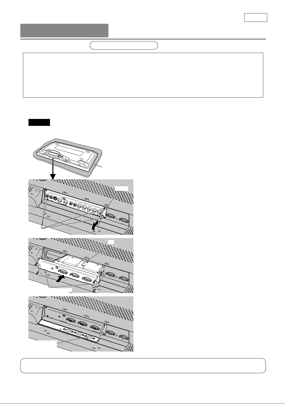
汚れや異物が付いていない柔らかい布の上に、ディスプレイ本体の前面部を下にして置き、以下の手順で行っ
てください。(下記はRGB アクティブスルー端子ボードに交換する場合の例です。)
●
お願い
必ずディスプレイ本体および接続機器の電源を切り、電源プラグをコンセントから抜き、接続
ケーブルをディスプレイ本体から外してください。
●
端子ボードの取り外し、取り付け時に金具でバックカバーや表示シートに傷を付けないようにしてください。
柔らかい布
ねじ(4本)
ツメに乗り上げないこと
溝
取っ手
1.
ディスプレイ本体から端子ボードを取り外す
1.ディスプレイ本体、後面部の端子ボードの取り付
けねじ(4本)を取り外す。
2.端子ボードの取っ手を持ち、ゆっくりと矢印方向
に引き抜く。
2.
交換する端子ボードを取り付ける
1.
溝に沿って挿入し、最後までしっかりと押し込む。
●
下側ツメ(2カ所)に乗り上げていないことを
確認してください。
2.取り外したねじ(4本)で①〜④の順に締め付け
て固定する。
3.
端子表示シートを貼り付ける
端子表示シート(付属)の裏面セパレーターをはが
し、すでに貼り付けてあるシート上に貼り付ける。
●
貼り付け方向に注意してください。
端子表示シート
(付属)
交換された端子ボードは、修理・サービスを受けられるときに必要となりますので、お客様にて保管していた
だくよう説明してください。
2
Page 3
Precautions:
• Before installation
Turn the power switch off and pull out the plug.
Disconnect any plugs connected to the Plasma Display.
• When removing or installing the Terminal Board, exercise care to avoid injury.
There may be some sharp-pointed solder joints on the rear side of the Board that could cause unexpected
injury.
• When installing the Board, note the following point:
Fully insert the Board into the slot horizontally until it is firmly plugged into the connector. Note that
incomplete insertion may damage the internal components.
•
Before proceeding with the replacement steps, be sure to turn off the entire system including the display, unplug
all components from their outlets, and disconnect all the interconnect cables from the display.
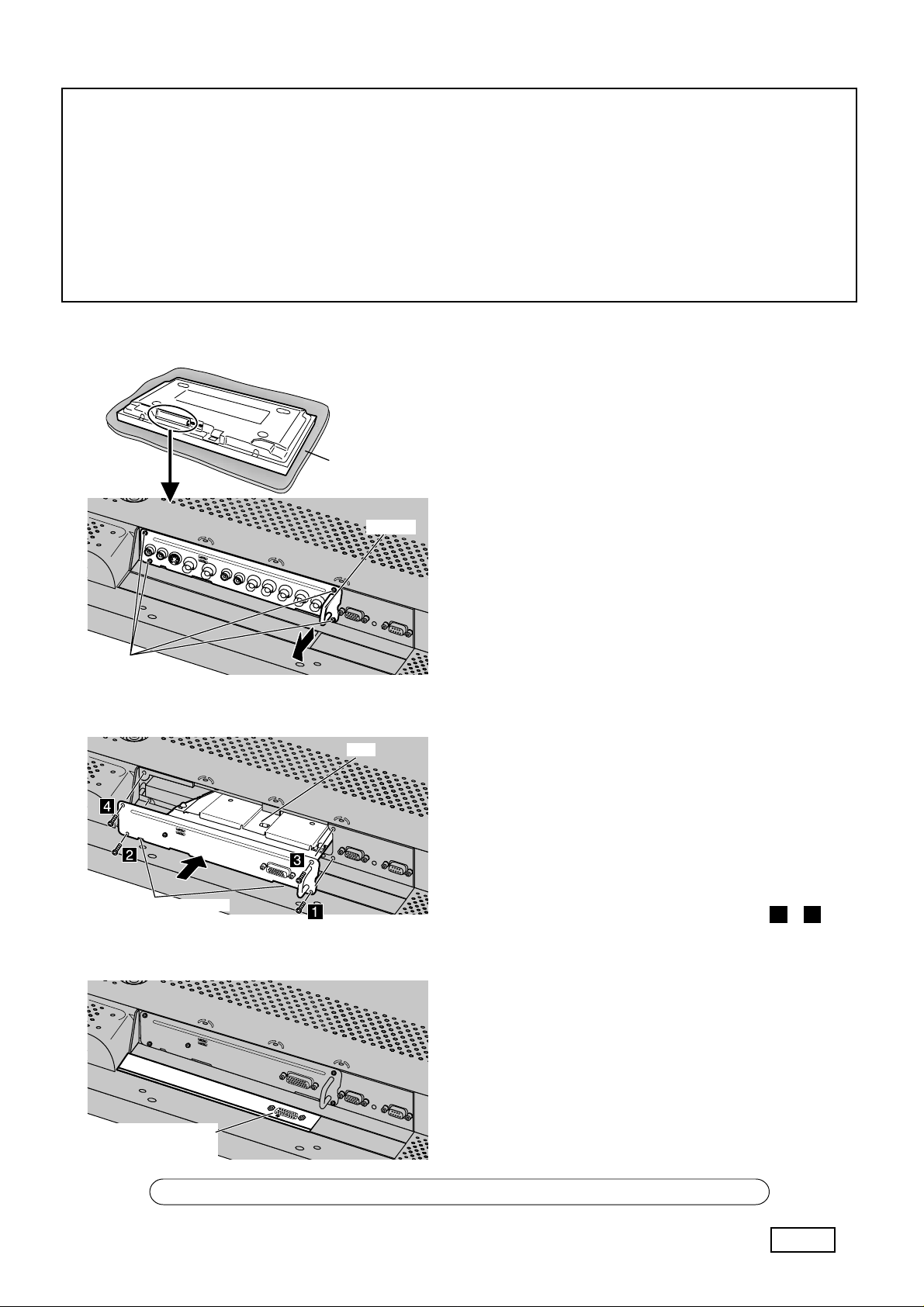
・Place the Plasma Display upside down on a soft surface,
such as a foam mat.
Foam mat or thick
soft cloth
1.
Removing the dummy cover or mounted
Side grip
terminal board from display:
1. Remove the four screws that secure the Terminal
Board to the rear of the display.
2. Hold the Terminal Board by the side grip and slowly
pull it out in the direction of the arrow.
Screws (x4)
( Example : When removing RCA Terminal Board )
Slot
Avoid riding on claws.
( Example : When installing Tuner Terminal Board )
2.
Installing desired Terminal Board:
( Example : When installing Tuner Terminal Board
)
1. Insert the desired Terminal Board into the slot until
it is firmly plugged into the card connector.
• Make sure that the Board does not ride on the
two lower claws.
2. Secure using the previously removed screws or
those supplied with the unit.
Tighten screws in the numbered order 1 - 4 .
3.
Applying the terminal function label:
Peel off the backing sheet from the terminal function
label (accessory) and affix it over the existing label.
• Make sure that the label is affixed with the correct
position.
Terminal function label
(accessory)
Have the customer keep the removed Terminal Board for future servicing needs.
English
3
Page 4
Vorsichtsmaßnahmen:
• Vor der Installation
Das Gerät ausschalten und das Netzkabel von der Steckdose abtrennen.
Alle am Plasmadisplay angeschlossenen Kabel abtrennen.
•
Beim Entfernen oder Einbauen des Terminal-Boards vorsichtig vorgehen, um Verletzungen zu vermeiden.
Auf der Rückseite des Boards können einige spitze Lötstellen vorhanden sein, die bei Berührung zu
Verletzungen führen können.
• Bei der Installation des Boards sollte folgendes beachtet werden:
Das Board horizontal in den Steckanschluß einschieben, bis es fest in die Steckverbindung eingesetzt ist.
Bitte beachten Sie, daß ein unvollständiges Einstecken die internen Bauteile beschädigen kann.
• Vor dem Ausführen der Schritte zum Austauschen des Boards sollte sichergestellt werden, daß das gesamte
System einschließlich des Displays und aller angeschlossenen Geräte von der Steckdose abgetrennt sind.
Darüberhinaus sollten alle Verbindungskabel vom Display abgetrennt werden.
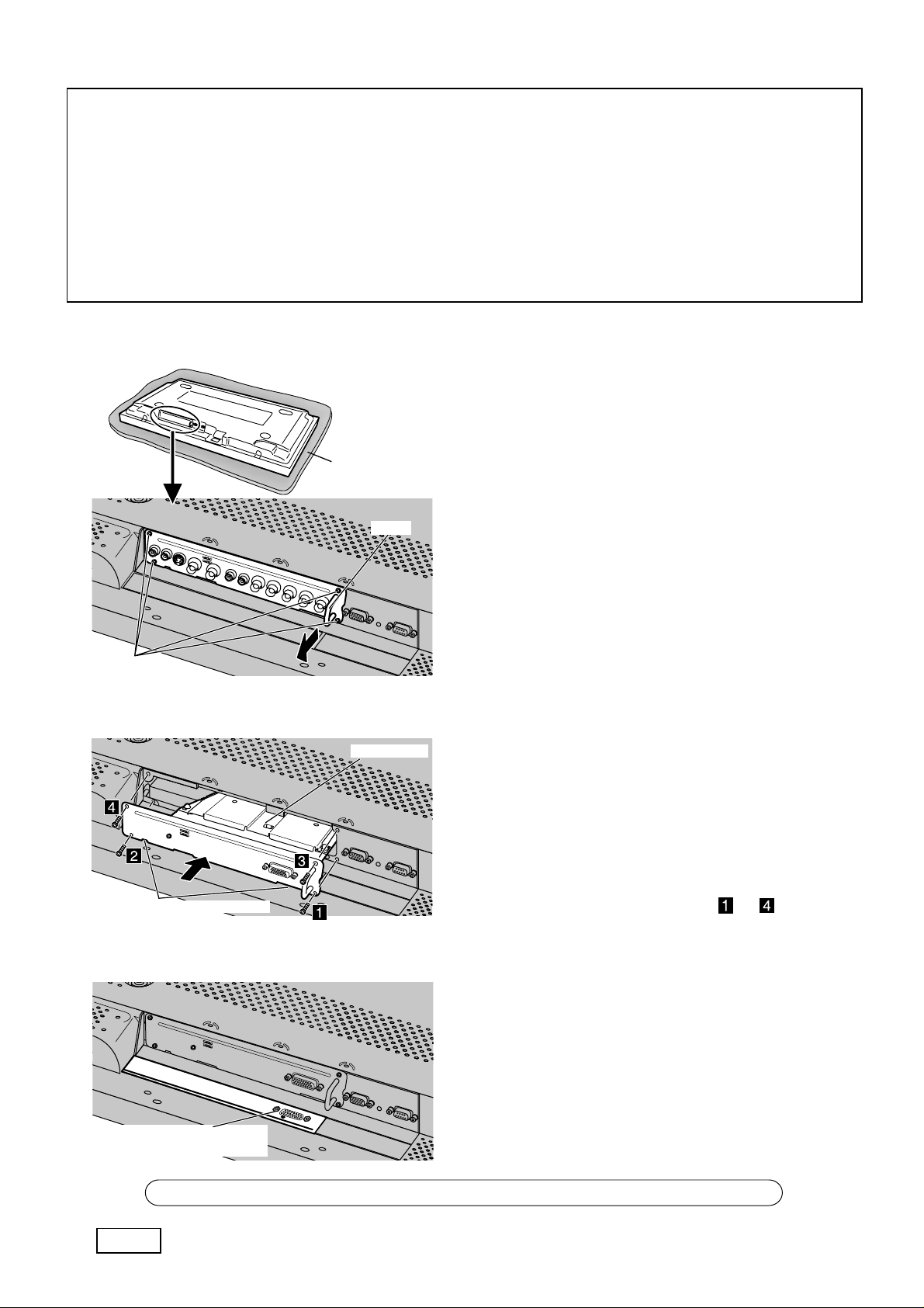
・Das Plasmadisplay mit der Vorderseite nach unten
weisend auf eine weiche Oberfläche legen, z.B. eine
Schaumstoffmatte.
Schaumstoffmatte oder
dickes, weiches Tuch
1.
Entfernen der Abdeckung oder des
Handgr
eingebauten Terminal-Boards vom Display:
1. Die vier Schrauben entfernen, mit denen das
Terminal-Board auf der Rückseite des Displays
befestigt ist.
2. Das Terminal-Board an den seitlichen Handgriffen
Schrauben
halten und langsam in Pfeilrichtung herausziehen.
(
Beispiel: Entfernen des RCA-Terminal-Boards
Nicht auf den Klammern schieben.
(
Beispiel: Einbau des Tuner-Terminal-Boards
Aufkleber für Terminal-Funktion
(Zubehör)
Steckplatz
)
)
2.
Einbau des Terminal-Boards:
(Beispiel: Einbau des Tuner-Terminal-Boards)
1. Das Terminal-Board in den Steckplatz schieben,
bis es fest im Kartenanschluß steckt.
• Sicherstellen, daß das Board nicht auf den
unteren Klammern geschoben wird.
2. Das Board mit den im obigen Schritt 1 entfernten
vier Schrauben am Display befestigen. Die
Schrauben in der Reihenfolge bis festdrehen.
3.
Anbringen des Aufklebers für TerminalFunktion:
Das rückwärtige Papier vom Aufkleber für die
Terminal-Funktion entfernen und über dem bisherigen
Aufkleber anbringen.
• Sicherstellen, daß der Aufkleber richtig ausgerichtet
angebracht wird.
4
Der Kunde sollte das entfernte Terminal-Board für zukünftigen Gebrauch aufbewahren.
Deutsch
Page 5

Voorzorgsmaatregelen:
• Alvorens te beginnen met de installatie
Schakel de apparatuur uit en trek de stekker uit het stopcontact.
Trek alle stekkers los die op het plasmadisplay zijn aangesloten.
•
Let er bij het verwijderen of aanbrengen van de aansluitingenkaart op dat u zich niet verwondt.
Er kunnen uitstekende soldeerpunten aan de achterkant van de kaart zijn waaraan u zich kunt verwonden.
• Neem het volgende in acht wanneer u de kaart in het apparaat monteert:
Steek de kaart horizontaal in de opening totdat deze stevig in de kaartconnector is vergrendeld. Bij een
foutieve montage kunnen de interne componenten van de kaart worden beschadigd.
• Voordat u begint met het vervangen van de kaart, moet u de volledige installatie inclusief het plasmadisplay uitschakelen, en
alle stekkers uit de stopcontacten trekken. Verbreek ook alle verbindingen tussen het plasmadisplay en de andere apparatuur.
・Leg het plasmadisplay ondersteboven op een zachte
ondergrond, zoals een schuimrubber mat.
Schuimrubber mat of
dikke zachte doek
1.
Verwijderen van de afdekplaat of de
Handgreep
aanwezige aansluitingenkaart uit het
display:
1. Verwijder de vier schroeven waarmee de
aansluitingenkaart aan de achterkant van het
display is bevestigd.
2. Houd de aansluitingenkaart bij de zijgrepen vast en
Schroeven (x4)
(Voorbeeld: Verwijderen van de RCA aansluitingenkaart)
trek de kaart langzaam in de richting van de pijl
naar buiten.
Opening
Let op dat de kaart
niet over de klemmen schuurt.
(Voorbeeld: Monteren van de tuner-aansluitingenkaart)
Aansluitingen-functielabel
(bijgeleverd)
2.
Monteren van de gewenste
aansluitingenkaart:
(Voorbeeld: Monteren van de tuner-aansluitingenkaart)
1. Steek de gewenste aansluitingenkaart in de gleuf
totdat deze stevig in de kaartconnector zit.
• Zorg dat de kaart niet over de twee onderste
klemmen schuurt.
2. Monteer de kaart met de voorheen verwijderde
schroeven of met de schroeven die bij de kaart
worden geleverd. Draai de schroeven vast in de
volgorde van tot .
3.
Het aansluitingen-functielabel
aanbrengen:
Verwijder de lijmbeschermlaag van het bijgeleverde
aansluitingen-functielabel en bevestig het label over
het aanwezige label heen.
• Let erop dat het label juist wordt aangebracht.
Zorg dat de klant de verwijderde aansluitingenkaart bewaard voor eventueel toekomstig gebruik.
Nederlands
5
Page 6

Precauzioni:
• Prima dell’installazione
Spegnere l’unità principale e sfilare la spina del cavo di alimentazione elettrica.
Sfilare tutte le spine collegate allo schermo al plasma.
•
Nel corso delle operazioni di installazione o estrazione della scheda dei terminali, fare attenzione ad evitare di ferirsi.
Ci possono essere alcuni giunti di saldatura taglienti dal lato posteriore della scheda terminali che
potrebbero provocare ferite inattese.
• Quando si installa la scheda terminali, si prega di prendere nota dei punti seguenti:
Inserire completamente la scheda terminali nella scanalatura orizzontalmente fino ad inserirla saldamente
nel connettore. Si noti che una inserzione non completa può danneggiare i componenti interni.
• Prima di procedere con le operazioni di rimontaggio, accertarsi di scollegare tutto il sistema compreso lo
schermo, scollegare tutti i componenti dalle uscite e tutti i cavi di interconnessione dallo schermo.
•
Capovolgere e mettere lo schermo al plasma su una
superficie morbida quale un tappetino di materiale espanso.
T appetino di materiale espanso
o panno soffice e spesso
1.
Estrazione del coperchio, o della scheda
Maniglia
dei terminali se montata, dallo schermo:
1. Rimuovere le quattro viti che fissano la scheda
terminali alla parte posteriore dello schermo.
2. Tenere la scheda terminali dalle prese laterali e
tirarla lentamente fuori nel senso della freccia.
Viti (x4)
Esempio: Estrazione della scheda dei terminali RCA
Scanalatura
Evitare di spostare sulle linguette.
Esempio: Installazione della scheda dei terminali
per il sintonizzatore
Etichetta di funzione dei
terminali (accessoria)
2.
Installazione della scheda dei terminali desiderata
Esempio:
Installazione della scheda dei terminali per il sintonizzatore
1. Inserire nella fessura la scheda dei terminali
desiderata, sino a quando risulta saldamente
fissata al connettore della scheda.
• Verificare per accertarsi che la scheda terminali
non si sposta sulle due linguette inferiori.
2. Fissare la scheda terminali allo schermo con le
quattro viti rimosse all’operazione 1 menzionata
precedentemente. Stringere le viti nell’ordine di
a .
3.
Come applicare l’etichetta funzione dei
terminali:
Staccare il foglio di protezione dall’etichetta di
funzione dei terminali accessoria e fissarla
sull’etichetta esistente.
• Accertarsi che l’etichetta è fissata nella direzione
corretta.
6
Il cliente deve conservare la scheda terminali rimossa per i futuri bisogni di assistenza.
Italiano
Page 7

Précautions:
• Avant l'installation
Mettez l'écran hors tension et débranchez la fiche du cordon d'alimentation au niveau de la prise secteur.
Débranchez tous les connecteurs qui seraient reliés à l'écran à plasma.
•
Lors de la dépose ou de l’installation d’une carte de connexion, faites très attention de ne pas vous blesser.
Il se peut que des points de soudure acérés existent sur la face arrière de la Carte et puissent causer des
blessures.
• Lors de l'installation de la Carte, tenez compte des points suivants:
Engagez la Carte à fond dans la fente horizontale jusqu'à ce qu'elle soit soigneusement reliée au
connecteur. Sachez que si l'insertion est partielle, les composants peuvent être endommagés.
•
Avant de procéder au remplacement, assurez-vous que tous les appareils, y compris l'écran, sont bien hors service, débranchez chaque
fiche de cordon d'alimentation et débranchez également tous les câbles qui relient l'écran aux autres appareils.
・Posez l'écran à plasma à l'envers, sur une surface molle
telle qu'un matelas de mousse.
Matelas en mousse
ou tissu doux épais
1.
Dépose du faux couvercle ou de la carte
Poignée
de connexion monté sur l’écran:
1. Déposez les 4 vis qui maintiennent la Carte de
connexion à l'arrière de l'écran.
2. Saisissez la Carte de connexion par les poignées
latérales et tirez-la lentement dans la direction de
Vis (x4)
la flèche.
(Exemple: Lors de l’installation d’une carte de connexion RCA)
Fente
2.
de connexion de tuner)
Evitez de faire
reposer sur les ergots.
(Exemple: Lors de l’installation d’une carte de connexion de tuner)
3.
Etiquette de carte de connexion
(fournie)
Installation de la carte de connexion souhaitée:
(Exemple: Lors de l’installation d’une carte
1. Engagez la carte de connexion souhaitée à fond
dans la fente jusqu’à ce qu’elle soit solidement
reliée au connecteur.
• Assurez-vous que la Carte ne repose pas sur les
2 ergots inférieurs.
2. Maintenez la Carte sur l'écran grâce au 4 vis
déposés précédemment ou des vis fournis avec
l’appareil. Serrez les vis dans l'ordre à .
Pose de l'étiquette de fonction:
Retirez la feuille de protection arrière de l'étiquette de
fonction (fournie) et posez cette étiquette sur celle qui
existe déjà.
• Assurez-vous de poser l'étiquette dans le bon sens.
Demandez au client de conserver la Carte de connexion retirée qui peut être nécessaire pour des réparations ultérieures.
Français
7
Page 8

Precauciones:
• Antes de hacer la instalación
Desconecte la alimentación con el interruptor de la alimentación y desenchufe la clavija.
Desconecte cualquier clavija que se encuentre conectada a la pantalla de plasma.
• Cuando retira o instala la regleta de terminales tenga cuidado para no herirse.
Es posible que existan puntos de soldadura puntiagudos en la cara posterior de la regleta que pueden
causar lesiones inesperadas.
• Cuando instale la regleta, tenga en cuenta el punto siguiente:
Inserte completamente la regleta en la ranura horizontalmente hasta que quede firmemente enchufada en
el conector. Tenga en cuenta que la inserción incompleta podría dañar los componentes internos.
• Antes de realizar los pasos de reemplazo, cerciórese de desconectar la alimentación de todo el sistema, incluyendo la pantalla,
desenchufar todos los componentes sus tomas de corriente, y desconectar todos los cables de interconexión de la pantalla.
・
Ponga la pantalla de plasma al revés encima de una
superficie blanda como, por ejemplo, una estera de espuma.
Estera de espuma o paño
blando y grueso
1.
Extracción de la cubierta ficticia o de la
Asa
regleta de terminales montada en la
pantalla:
1. Extraiga los cuatro tornillos que aseguran la regleta
de terminales a la parte posterior de la pantalla.
2. Sujete la regleta de terminales por las asas
Tornillos (x4)
(Ejemplo: Cuando retira la regleta de terminales RCA)
laterales y tire lentamente de ella hacia afuera en
el sentido de la flecha.
2.
Instalación de la regleta de terminales deseada:
Ranura
(Ejemplo: Cuando se instala la regleta de
terminales de sintonizador)
1. Inserte la regleta de terminales deseada en la
ranura hasta que quede firmemente enchufada en
el conector de regleta.
• Cerciórese de que la regleta no esté tocando las
Evite tocar las uñas.
(Ejemplo: Cuando instala la regleta de terminales de sintonizador)
3.
dos uñas inferiores.
2. Asegure la regleta con los cuatro tornillos
extraídos previamente o con los suministrados con
la unidad. Apriete los tornillos en el orden de
a .
Pegado de la etiqueta de función de los
terminales:
Despegue la lámina posterior de la etiqueta de
función de los terminales (accesoria) y péguela sobre
la etiqueta existente.
Etiqueta de función de los
terminales (accesoria)
• Cerciórese de pegar la etiqueta con la orientación
correcta.
8
Diga al cliente que conserve la regleta de terminales extraída por si se necesita en futuras reparaciones.
Español
Page 9

Försiktighetsåtgärder:
• Före installation
Slå av strömmen och koppla ur nätkabeln.
Koppla bort eventuella andra kablar som är anslutna till plasmaskärmen.
Var försiktig så att du inte skadar dig vid borttagning eller installation av uttagsplattan.
•
Det förekommer en del spetsiga lödningspunkter på plattans baksida som kan orsaka skärsår.
• Observera det följande vid installation av plattan:
Skjut in plattan vågrätt i skåran och tryck in den tills den är ordentligt ansluten till kontakten. De inre
delarna kan skadas om plattan inte är intryckt till fullo.
• Före borttagning av plattan ska du slå av hela systemet inklusive skärmen, koppla bort alla komponenter
från strömkällan och koppla bort alla kablar som är anslutna till skärmen.
・Placera plasmaskärmen upp och ned på ett mjukt underlag,
t.ex. en filt eller matta.
Tjock matta eller filt
1.
Borttagning av blindlocket eller den
Handtag
monterade uttagsplattan från skärmen:
1. Avlägsna de fyra skruvarna som fäster
uttagsplattan på skärmens baksida.
2. Håll uttagsplattan i sidogreppen och dra försiktigt ut
den i pilens riktning.
Skruvar (x4)
(Exempel: Borttagning av RCA uttagsplattan)
Skåra
Undvik att vila på ramarna
(Exempel: Installation av tuneruttagsplattan)
2.
Installation av önskad uttagplatta:
(Exempel: Installation av tuneruttagsplattan)
1. Skjut in önskad uttagsplatta i skåran tills den är
ordentligt ansluten till kortkontakten.
• Försäkra att uttagsplattan inte vilar på de två
undre ramarna.
2. Skruva fast plattan på skärmen med de fyra
skruvar som avlägsnades i steg 1 ovan. Dra åt
skruvarna i ordningen till .
3.
Fäste av etiketten för uttagsfunktion:
Skala av bakstycket på den medföljande etiketten för
uttagsfunktion och fäst den över den existerande
etiketten.
• Kontrollera att etiketten är fäst rättvänd.
Etikett för uttagsfunktion
(medföljer)
Se till att kunden bevarar den borttagna uttagsplattan för framtida servicebehov.
Svenska
9
Page 10

Forsigtighedsregler:
• Før installation
Sluk for afbryderen og træk netledningens stik ud af stikkontakten.
Udtag alle stik, der er tilsluttet til plasmaskærmen.
•
Ved fjernelse eller installation af terminalkortet skal der udvises forsigtighed, så tilskadekomst undgås.
Der kan være skarpe og spidse lodninger på bagsiden af kortet, som kan medføre tilskadekomst i tilfælde
af uopmærksomhed.
• Bemærk følgende, når kortet installeres:
Før kortet vandret og helt ind i kortpladsen, indtil det er sikkert tilsluttet konnektoren. Bemærk, at
ufuldstændig isætning kan medføre skade på indvendige komponenter.
• Før du går videre med udskiftningen, skal du sikre dig, at der er slukket for hele systemet, inklusive plasmaskærmen, at netledningerne
til alle komponenter er taget ud af forbindelse, og at alle kabler, der benyttes ved tilslutninger til plasmaskærmen, er afbrudt.
・Anbring plasmaskærmen med forsiden nedad på en blød
overflade, eksempelvis en skummåtte.
Skummåtte eller tykt,
blødt klæde
1.
Fjern blinddækslet eller et monteret
Håndtag
terminalkort fra skærmen:
1. Fjern de fire skruer, der holder terminalkortet på
bagsiden af skærmen.
2. Hold terminalkortet i sidehåndtagene, og træk
langsomt kortet ud i pilens retning.
Skruer (x4)
(Eksempel: Ved afmontering af RCA terminalkortet)
Sprække
Undgå at kortet hviler på griberne
(Eksempel: Ved installation af Tuner terminalkortet)
Terminalfunktionsmærkat
(tilbehør)
2.
Installation af det ønskede terminalkort:
(Eksempel: Ved installation af Tuner terminalkortet)
1. Før det ønskede terminalkort ind i sprækken, indtil
det er sikkert tilsluttet kortkonnektoren.
• Kontrollér, at kortet ikke hviler på de to griber på
undersiden.
2. Fastgør kortet til skærmen med de 4 skruer, der
tidligere blev fjernet, eller med dem, der følger med
kortet. Stram skruerne i rækkefølge fra
til .
3.
Påsætning af terminalfunktionsmærkaten:
Træk beskyttelsesfilmen af bagsiden på
terminalfunktionsmærkaten og anbring mærkaten
oven på den gamle mærkat.
• Sørg for, at mærkaten vender rigtigt, når den sættes
på.
10
Bed kunden om at opbevare det fjernede terminalkort for eventuel brug ved servicering i fremtiden.
Dansk
Page 11

:
•
•
•
.
•
. .
.
.
, .
.
, :
.
: RCA )
(
( : )
•
.
1.
:
1.
4
.
2.
2.
: )
(
1.
•
.
2.
.
1 - 4 .
.
:
.
2
3.
:
( )
.
•
.
.
日本語
11
Page 12

12
Matsushita Electric Industrial Co., Ltd.
Web Site : http://www.panasonic.co.jp/global/
MS0602S0
 Loading...