

Panasonic TX-51P950M, TX-51P950X Schematic
ORDER NO.PAVCSH200507005C3
Projection Television
TX-51P950M
TX-51P950X
TX-43P950M
TX-43P950X
GP11N-VP
Specifications
|
TX-43P950M / TX-51P950M |
TX-43P950X/TX-51P950X |
Power Source |
AC 220 - 240 V, 50 / 60 Hz |
AC 220 - 240 V, 50 / 60 Hz |
Power Consumption |
Stand-by condition: less than 1W |
Stand-by condition: 0.5 W |
|
Normal viewing: 165 W(43"),170W (51") |
Normal viewing : 165W(43"),170W(51") |
|
TX-43P950M / X |
TX-51P950M/X |
Dimensions (W × H × D) |
1095 mm × 1267.5 mm × 518 mm |
1298 mm × 1394 mm × 518 mm |
Mass (Weight) |
58 kg (Net) |
68 kg (Net) |
Remote control Transmitter |
N2QAJB000109 |
|
|
R6 (AA) Battery × 2 |
|
Receiving System |
|
|
© 2005 Matsushita Electric Industrial Co., Ltd. All rights reserved. Unauthorized copying and distribution is a violation of law.

TX-51P950M / TX-51P950X / TX-43P950M / TX-43P950X
Receiving Channels |
Regular TV |
|
|
VHF BAND |
|
|
2-12 (PAL/SECAM B, K1) |
|
|
0-12 (PAL B AUST.) |
|
|
1-9 (PAL B N.Z) |
|
|
1-12 (PAL/SECAM D) |
|
|
1-12 (NTSC M Japan) |
|
|
2-13 (NTSC M U.S.A) |
|
|
UHF BAND |
|
|
21-69 (PAL G, H, I/SECAM G, K, K1) |
|
|
28-69 (PAL AUST.) |
|
|
13-57 (PAL D, K) |
|
|
13-62 (NTSC M Japan) |
|
|
14-69 (NTSC M U.S.A) |
|
|
CATV |
|
|
S1-S20 (OSCAR) |
|
|
1-125 (U.S.A CATV) |
|
|
C13-C49 (JAPAN) |
|
|
S21-S41 (HYPER) |
|
|
Z1-Z37 (CHINA) |
|
|
5A, 9A (AUST.) |
|
Receiving Stereo System |
NICAM I, NICAM B/G, NICAM D, A2 (German) |
|
Tuning System |
Frequency synthesizer |
Auto Search Tuning |
|
|
POSITION: 100 Position |
|
|
DIRECT: 125 Position |
Audio Output |
24W [12 W +12 W] (10 % THD) |
|
Speaker System |
Woofer × 2 + Squawker × 2 |
|
Headphones |
3.5 mm Plug × 1 |
|
Aerial Impedance |
75 Ω Unbalanced coaxial |
|
Video / Audio / Component Terminals |
|
|
AV 1, 2, 3, 4, |
S Video In |
Y: 1 V p-p, 75 Ω |
|
|
C: 0.3 V p-p, 75 Ω |
|
DVD (Y/ PB/ PR) |
|
|
Video In |
1 V p-p, 75 Ω |
|
Audio In |
Approx. 0.5 V 47 KΩ |
Monitor Out |
Video Out |
1 V p-p, 75 Ω |
|
Audio Out |
Approx. 0.5 V, 1 KΩ |
2

TX-51P950M / TX-51P950X / TX-43P950M / TX-43P950X
AV1 IN (Rear): S Video, Video, Audio L/R terminals
AV2 IN (Rear): Video or Y/ PB/ PR, Audio L/R terminals
AV3 IN (Front): S Video, Video, Audio L/R terminals
AV4 IN (Rear): Video or Y/ PB/ PR, Audio L/R terminals
Applicable signal to AV2, AV4 Y/ PB/ PR input terminals: 480i (525i), 576i (625i), 480P (525P) and 576P (625P)
Notes: Design and Specifications are subject to change without notice. Weight and Dimensions shown are approximate.
CONTENTS
|
|
Page |
|
Page |
1 |
Safety Precautions |
5 |
8.3. PAL Progressive mode (50p) |
25 |
|
1.1. General Guide Lines |
5 |
8.4. NTSC Progressive mode (60p) |
25 |
|
1.2. Leakage Current Cold Check |
5 |
8.5. 525i/525p Deflection Adjustment / Confirmation |
26 |
|
1.3. Leakage Current Hot Check (See Fig.1) |
5 |
8.6. 625i/625p Deflection Adjustment / Confirmation |
26 |
|
1.4. X-Radiation |
5 |
9 Adjustment Procedure |
27 |
2 |
Chassis Board Layout |
6 |
9.1. Cut off Adjustment |
27 |
3 |
Disassembly for Service |
7 |
9.2. Sub Contrast Adjustment |
28 |
|
3.1. Disassembly Flowchart |
7 |
9.3. Sub Color Adjustment |
28 |
|
3.2. Cabinet Side (L, R) |
8 |
9.4. Blue Focus / Gamma Adjustment |
29 |
|
3.3. Speaker Grille |
8 |
9.5. White Balance Adjustment |
29 |
|
3.4. Speaker Ass y |
8 |
9.6. Sub Bright Adjustment |
30 |
|
3.5. Cabinet (Top) |
9 |
9.7. Blue Limit Adjustment |
30 |
|
3.6. Speaker (Top Cabinet) |
9 |
10 Convergence Adjustment |
31 |
|
3.7. Screen |
9 |
10.1. Convergence Adjutment Sheet |
31 |
|
3.8. Mirror |
10 |
10.2. Convergence Adjustment Procedure |
32 |
|
3.9. Rear Cover (Top) |
10 |
10.3. Coarse Convergence Adjustment mode |
33 |
|
3.10. Rear Cover (Bottom) |
10 |
10.4. Fine Convergence Adjustment |
39 |
|
3.11. Disassembly For CRT Removal |
11 |
11 Location of Lead Wiring |
43 |
4 |
Service Hints |
12 |
11.1. Location of Lead Wiring (1) |
43 |
|
4.1. Service position for Main chassis |
12 |
11.2. Location of Lead Wiring (2) |
45 |
|
4.2. Service Position for DG-Board |
12 |
12 Conductor Views |
47 |
|
4.3. Service Position for K-Board |
12 |
12.1. A-Board |
47 |
|
4.4. Service Position for KA-Board |
13 |
12.2. D-Board |
50 |
|
4.5. VOLTAGE CHART |
13 |
12.3. DG-Board |
52 |
5 |
Self Check |
14 |
12.4. DC-Board |
53 |
6 |
Service Mode Function |
15 |
12.5. H-Board & KA-Board |
54 |
|
6.1. How to enter SERVICE 1 |
15 |
12.6. GK-Board |
55 |
|
6.2. How to enter SERVICE 2 |
15 |
12.7. LB-Board |
56 |
|
6.3. Option Descrition |
17 |
12.8. LR-Board & LG-Board |
57 |
7 |
CRT Set Up |
20 |
13 Schematic Diagram |
59 |
|
7.1. Dynamic Focus Adjustment |
20 |
13.1. Schematic Diagram Notes |
59 |
|
7.2. Electrical Focus Adjustment |
20 |
13.2. A-Board (1 of 4) Schematic Diagram |
60 |
|
7.3. Optical Lens Focus Adjustment |
20 |
13.3. A-Board (2 of 4) Schematic Diagram |
61 |
|
7.4. Centering Magnet Adjustment |
21 |
13.4. A-Board (3 of 4) Schematic Diagram |
62 |
|
7.5. Alignment magnet Adjustment |
22 |
13.5. A-Board (4 of 4) Schematic Diagram |
63 |
8 |
Deflection Adjustment |
23 |
13.6. D-Board (1 of 2) Schematic Diagram |
64 |
|
8.1. PAL 100Hz mode (100i) |
23 |
13.7. D-Board (2 of 2) Schematic Diagram |
65 |
|
8.2. PAL 100Hz V Comp mode (100i) |
24 |
13.8. DC-Board Schematic Diagram |
66 |
3

TX-51P950M / TX-51P950X / TX-43P950M / TX-43P950X
13.9. |
DG-Board (1 of 6) Schematic Diagram |
67 |
|
13.18. LG-Board Schematic Diagram |
76 |
13.10. |
DG-Board (2 of 6) Schematic Diagram |
68 |
|
13.19. LR-Board Schematic Diagram |
77 |
13.11. |
DG-Board (3 of 6) Schematic Diagram |
69 |
14 |
Parts Location |
79 |
13.12. |
DG-Board (4 of 6) Schematic Diagram |
70 |
15 |
Packing Exploded View |
81 |
13.13. |
DG-Board (5 of 6) Schematic Diagram |
71 |
16 |
Mechanical Replacement Parts List |
83 |
13.14. |
DG-Board (6 of 6) Schematic Diagram |
72 |
17 |
Electrical Replacement Parts List |
85 |
13.15. |
H and KA-Board Schematic Diagram |
73 |
|
17.1. Replacement Parts List Notes |
85 |
13.16. |
GK-Board Schematic Diagram |
74 |
|
17.2. Electrical Replacement Parts List |
86 |
13.17. |
LB-Board Schematic Diagram |
75 |
|
|
|
4

1 Safety Precautions
1.1.General Guide Lines
1.It is advisable to insert an isolation transformer in the AC supply before servicing a hot chassis.
2.When servicing, observe the original lead dress, especially the lead dress in the high voltage circuits.
If a short circuit is found, replace all parts which have been overheated or damaged by the short circuit.
3.After servicing, see to it that all the protective devices such as insulation barriers, insulation papers, shields, and isolation R-C combinations, are properly installed.
4.When the receiver is not to be used for a long period of time, unplug the power cord from the AC outlet.
5.Potential, as high as 30.0kV, is present when this monitor is in operation. Operation of the Projection Monitor without the rear cover involves the danger of a shock hazard from the power supply. Servicing should not be attempted by anyone who is not thoroughly familiar with the precautions necessary when working on high voltage equipment. Always discharge the anode of the projection tube to the Projection Monitor chassis before handling the tube.
6.After servicing make the following leakage current checks to prevent the customer from being exposed to shock hazards.
1.2.Leakage Current Cold Check
1.Unplug the AC cord and connect a jumper between the two prongs on the plug.
2.Turn on the Projection Monitor´s power switch.
3.Measure the resistance value, with an ohmmeter, between the jumpered AC plug and each exposed metallic cabinet part on the projection monitor, such as screw heads, connectors, control shafts, etc. When the exposed metallic part has a return path to the chassis, the reading should be between 4 MΩ and 20 MΩ .
When the exposed metal does not have a return path to the chassis, the reading must be  .
.
1.3.Leakage Current Hot Check (See Fig.1)
1.Plug the AC cord directly into the AC outlet. Do not use an isolation transformer for this check.
2.Connect a 2kΩ , 10W resistor, in series with an exposed metallic part on the projection monitor and an earth such as a water pipe.
3.Use an AC voltmeter, with high impedance type, to measure the potential across the resistor.
4.Check each exposed metallic part, and measure the voltage at each point.
5.Reverse the AC plug in the AC outlet and repeat each of the above measurements.
6.The potential at any point should not exceed 1.0V rms. In case a measurement is outside of the limits specified, there is a possibility of a shock hazard, and the projection monitor should be repaired and rechecked before it is returned to the customer.
TX-51P950M / TX-51P950X / TX-43P950M / TX-43P950X
Fig. 1
1.4.X-Radiation
Warning :
1.The potential sources of X-Radiation in projection monitor are the High Voltage section and the projection tube.
2.When using a projection tube test jig for service, ensure that jig is capable of handling 31.5kV without causing X- Radiation.
Note:
It is important use an accurate periodically calibrated high voltage meter.
1.Set the brightness to minimum.
2.Set the service switch to the service position.
3.Measure the High Voltage. The meter reading should indicate 31.5(+1.0,-1.5kV). If the meter indication is out of tolerance, immediate service and correction is required to prevent the possibility of premature component failure.
4.To prevent an X-Radiation possibility, it is essential to use the specified projection tube.
5

TX-51P950M / TX-51P950X / TX-43P950M / TX-43P950X
2 Chassis Board Layout
Board-Name |
Function |
A-Board |
Main Signal, Digital Converter,Line Filter |
D-Board |
Deflection, High Voltage |
LR-Board |
CRT Drive (R) |
LG-Board |
CRT Drive (G) |
LB-Board |
CRT Drive (B) |
H-Board |
Rear terminal |
DG-Board |
Digital Core,MPU,AV Switch |
DC-Board |
Convergence |
GK-Board |
Front Terninal,Power Switch,Front Control panel |
KA-Board |
Blue light |
6

TX-51P950M / TX-51P950X / TX-43P950M / TX-43P950X
3 Disassembly for Service
This flowchart indicates disassembly items of the cabinet parts and circuit boards in order to find the items necessary for servicing, when reassembling, perform the procedures in the reverse order.
3.1.Disassembly Flowchart
7
TX-51P950M / TX-51P950X / TX-43P950M / TX-43P950X
Note:
Board ground wires may have to be disconnected to disassemble some boards. All ground wires must be reconnected using jumper leads if necessary before power is applied to Receiver for service.
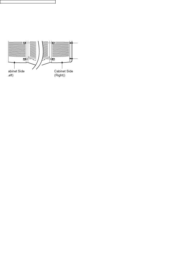
3.2.Cabinet Side (L, R)
1. Remove (14) screws.
3.3.Speaker Grille
1. Remove (8) screws.
3.4. Speaker Ass´y
1. Remove (10) screws.
2. Remove (2) screws.
8

TX-51P950M / TX-51P950X / TX-43P950M / TX-43P950X
3.6. Speaker (Top Cabinet)
3.5.Cabinet (Top)
1. Remove (12) Screws.
3.7. Screen
1. Remove (20) nails, and remove (2) Screen Holders (vertical side) and (4) Screen Holders (horizontal side).
9

TX-51P950M / TX-51P950X / TX-43P950M / TX-43P950X
3.8. Mirror |
3.10. Rear Cover (Bottom) |
1. Remove (3) screws. |
1. Remove (15) screws. |
|
2. Remove (1) screw. |
3.9.Rear Cover (Top)
1.Remove the Top Cabinet.
2.Remove (2) screws.
10
3.11. Disassembly For CRT Removal
To facilitate CRT replacement, the complete CRT mounting chassis does not need to be removed.
1.Remove the Screen Frame Ass´y, Decorative Panel and the Bottom Rear Cover Ass´y. ( See Disassemble for Service ).
2.Unplug the defective CRT Dag ( GND ), from the CRT Board, LBGND for LB, LGGND for LG, LRGND for LR.
3.Remove lead wires ( DY, VM coil ) and anode lead wire from holders as necessary.
4. Remove the CRT Board from the defective CRT neck.
TX-51P950M / TX-51P950X / TX-43P950M / TX-43P950X
7.Release CRT anode lead from CRT chassis wire clamp and all other wires from holders.
8.Wire the anode lead wire.
9.Lift out CRT assembly with lens assembly and other CRT neck assemblies.
10.Lay CRT face down on a soft cloth.
11.Remove CRT lens by removing (4) screws.
12.Install yoke and VM coil with other CRT neck assemblies on CRT neck in the same order and position as removed from the defective CRT.
13.Push yoke against bell of CRT and tighten the clamp just snug enough so it will not easily shift.
14.Assemble CRT focus lens assembly to new CRT with (4) screws. Make sure focus lens adjustment nut is in the same location as on other CRT focus lens.
Note:
Please assemble with screws in the order shown in detail and tighten with same torque.
5.Note position of yoke with centering tabs and remove from defective CRT.
6.From the Top, remove (2) screws from the defective CRT.
11
TX-51P950M / TX-51P950X / TX-43P950M / TX-43P950X
4 Service Hints
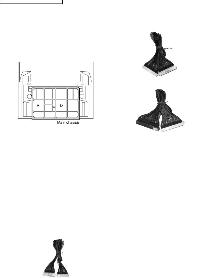
4.1.Service position for Main chassis
PART No. :GP11(N)-2
1.Remove the Rear Cover (Bottom) by removing (15) screws and (1) screws around its perimeter.
2.Remove lead wires and bundles from holders as necessary.
3.Pull out main chassis and stand it.
PART No. :GP11(N)-3
4.2.Service Position for DG-Board
1.Remove the each circuit board from A or D-Board.
2.Connect extension cables between individual circuit board and A or D-Board.
Note:
Extension cable kit is supplied as service fixtures and tools.
PART No. :GP11(N)-1
4.3.Service Position for K-Board
1.Remove the Speaker Grille.
2.Remove the K-Board by (4) screws.
12

TX-51P950M / TX-51P950X / TX-43P950M / TX-43P950X
4.4.Service Position for KA-Board
1.Remove the Speaker Grille.
2.Remove the Terminal Door by (4) screws.
3. Remove the KA-Board.
4.5.VOLTAGE CHART
D-BOARD
A-BOARD
SUPPLY |
TEST POINT |
VOLTAGE |
|
12V ~ GND |
A5 PIN9 |
11.9 ± 0.45V |
|
TNR-5V ~ GND |
IC001 PIN3 |
5.0V |
± 0.4V |
9V ~ GND |
IC058 PIN3 |
9.0V |
± 0.4V |
8V ~ GND |
IC2000 PIN2 |
8.0V |
± 0.4V |
5V ~ GND |
IC2002 PIN3 |
5.0V |
± 0.4V |
3.3V ~ GND |
IC065 PIN2 |
3.2V |
± 0.2V |
2.5V ~ GND |
IC1402 PIN4 |
2.5V |
± 0.25V |
Heater Voltage And High Voltage
|
|
TPLB3(+) ~ TPLB2(-) |
6.3 ± 0.24VRMS |
High Voltage |
31.5+1.0KV,-1.5KV |
13

TX-51P950M / TX-51P950X / TX-43P950M / TX-43P950X
5Self Check
1.Self-Check is used to automatically check the bus lines and hexadecimal code of the TV set.
2.To get into the Self -Check mode press the down (  ) button on the customer controls at the front of the set, at the same time pressing the OFF Timer button on the remote control, and the screen will show :
If the CCU ports have been checked and found to be incorrect or not located then “--” will appear in place of “O.K.”.
Display |
Ref. No. |
Description |
P.C.B. |
MEM |
IC1404 |
Memory |
A-Board |
GC3FM |
IC4001 |
Grobal Core MAIN |
DG-Board |
GC4U |
IC4401 |
Grobal Core SUB |
DG-Board |
AVSW1 |
IC3001 |
AV Switch |
DG-Board |
AVSW2 |
IC3002 |
AV Switch |
DG-Board |
TNU1 |
TU1 |
Tuner |
A-Board |
DAC2 |
IC1101 |
DAC Control2 |
DG-Board |
MSP |
IC2001 |
Stereo Decoder |
A-Board |
CONV |
IC7103 |
Convergence |
DC-Board |
CVDAC |
IC7106 |
CONV. DAC |
DC-Board |
14

TX-51P950M / TX-51P950X / TX-43P950M / TX-43P950X
6 Service Mode Function
MPU controls the functions switching for each IICs through IIC bus in this chassis. The following setting and adjustment can be adjusted by remote control in Service Mode.
6.1. How to enter SERVICE 1
1. In sound menu, set BASS to MAX, and set TREBLE to MINIMUM.
2. Simultaneously press RECALL button on remote control and VOLUME DOWN button [ - ] on the TV set.
6.2. How to enter SERVICE 2
1.Set the channel to CH99.
2.Press HOLD button on remote control.
Note:
To exit to Service mode, press N or Power button on remote control.
15

TX-51P950M / TX-51P950X / TX-43P950M / TX-43P950X
16

TX-51P950M / TX-51P950X / TX-43P950M / TX-43P950X
6.3.Option Descrition
17

TX-51P950M / TX-51P950X / TX-43P950M / TX-43P950X
18

TX-51P950M / TX-51P950X / TX-43P950M / TX-43P950X
19

TX-51P950M / TX-51P950X / TX-43P950M / TX-43P950X
7 CRT Set Up
Caution:
Insure yoke plugs on the A-Board are reconnected before turning the Receiver ON to prevent damage to the horizontal output transistor and/or CRTs.
7.1.Dynamic Focus Adjustment
1.Focus adjustments should be performed after 1 hour of aging.
2.Use oscilloscope with 100 : 1 probe.
3.Apply PAL monoscope pattern.
4.Set scan mode to 100Hz.
5.Set the picture menu to Dynamic.
6.Set the DAF V-SAW data: 7.
7.Adjust the Red, Blue and Green focus VR on the focus block for best focus of overall picture of each CRT. (Fig. 2)
Fig. 2
8.Connect the scope probe to TPD20, GND to TPD21. Scope set at 20V/div & 5m sec./div.
9.Adjust V-PARA (Service mode1) so that waveform (A) is 360V ± 20V. (Fig. 3)
10.Adjust H-PARA (Service mode1) so that waveform (B) is 560V + 40V,-60V. (Fig. 3)
Fig. 3
11.Set scan mode to PAL 100V Comp.
12.Set the picture menu to Dynamic.
13.Adjust V-PARA (Service model) so that waveform (A) is 260V ± 20V. (Fig. 3)
14.Adjust H-PARA (Service model) so that waveform (B) is 560V + 40V, -60V. (Fig. 3)
15.Set scan mode to Progressive.
16.Repeat step 7-10.
17.Apply NTSC monoscope pattern.
18.Set scan mode to Progressive.
19.Repeat step 7-10.
20.Set scan mode to 100Hz.
21.Repeat step 7-10.
22.Proceed with Focus Adjustments.
7.2.Electrical Focus Adjustment
1.Receive a monoscope pattern.
2.Cover the Red and Blue CRT, projecting Green only.
The electrical focus controls are located on the front. Adjust the Green Focus VR for best focus of overall picture. (Fig. 2)
3.Repeat for Red focus VR while projecting Red only.
4.Repeat for Blue. (Best focus at bottom left corner of screen)
7.3.Optical Lens Focus Adjustment
Note:
This adjustment normally should not require resetting unless the lens has been replaced or adjustment has changed.
1.Optical focus adjustment is located on the top of each CRT lens system. Loosen the adjustment knurls locking knob. (Fig. 4)
Fig. 4 (Rear view)
2.Turn the Receiver ON apply and view a monoscope pattern.
3.Adjust each lens focus for best focus while viewing each CRT.
4.Cover the Red and Blue CRT, projecting green only.Rotate the Green lens for best focus around screen center area.
5.Do the same for the Red focus lens while projecting Red only.
6.Repeat for Blue.
20
TX-51P950M / TX-51P950X / TX-43P950M / TX-43P950X
7.4.Centering Magnet Adjustment
1.Receive a monoscope pattern.
2.Set that Fine convergence data (Service mode1) is clear (no correction).
3.Set that V-Pos data (Service mode1) is [130].
4.Set that H-Pos data (Service mode1) is [954].
5.Set that H-Parallel data (Service mode1) is [16].
Procedure:
1.Cover the Red, Blue CRT lens, projecting Green only.
2.Adjust green centering magnet (DY) if the projected green horizontal/vertical line does not line up with the screen horizontal/vertical center line.
3.Cover the Green, Red CRT lens, projecting Blue only.
4.Repeat step 2. for blue.
5.Cover the Green, Blue CRT lens, projecting Red only.
6.Repeat step 2. for red.
7.Cover the Red, Blue CRT lens, projecting Green only.
8.Adjust green centering magnets until the center of the monoscope pattern line up with the screen center line.
9.Cover the Green, Red CRT lens, projecting Blue only.
10.Adjust blue centering magnets to position the center of the blue raster W2 away from the center of the green raster.
11.Cover the Green, Blue CRT lens, projecting Red only.
12.Adjust red centering magnets to position the center of the red raster W1 away from the center of the green raster.
21

TX-51P950M / TX-51P950X / TX-43P950M / TX-43P950X
7.5.Alignment magnet Adjustment
Preparation:
1.Receive an cross hatch pattern with dots (pincushion).
2.Loosen the centering magnets screws.
3.Position the longer tab of the four-pole magnet to 90 degrees (uncorrected position).
VM Coil with focus correction magnet
4-pole magnet
4.Position the long tab of all alignment magnets and of the dummy ring together in an uncorrected position.
Alignment magnet (or dummy ring)
Procedure:
1.Receive an cross hatch pattern with dots.
2.Cover the Red, Blue CRT lens, projecting Green only.
3.Turn the green electrical focus adjustment VR (on focus pack) fully counterclockwise and note the position of the dots at the center of the picture.
4.Turn the green electrical focus adjustment VR fully clockwise.
5.Adjust the four pole magnets until the shape of the dot at the center of the screen is circular.
6.Adjust for best green electrical focus with green electrical focus adjustment VR.
7.Cover the Green, Red CRT lens, projecting Blue only.
8.Repeat step 4. ~ step 6. for blue electrical focus.
9.Cover the Green, Blue CRT lens, projecting Red only.
10.Repeat step 4. ~ step 6. for red electrical focus.
11.Receive an monoscope pattern.
12.Cover the Red, Blue CRT lens, projecting Green only.
13.If the center of the monoscope pattern is not inside the 15mm circle, shown in below, adjust the centering magnets. Repeat the alignment magnet adjustments and four pole magnet adjustments (step 1. ~ step 6.)
Centering magnet adjustment
14.Cover the Green, Blue CRT lens, projecting Red only.
15.Repeat step 13. for the red.
16.Cover the Green, Red CRT lens, projecting Blue only.
17.Repeat step 13. for the blue.
18.Following adjustments, fix the centering magnets of DY, dummy rings of VM coil, four pole magnets of VM coil and the alignment magnets of VM coil to prevent them from moving.
22

8 Deflection Adjustment
Caution
1.The following adjustment have to be carried out one with PAL signal (100i/50p) and with NTSC signal (60p/120i).
2.Deflection adjustment need to set the Coarse/Fine Convergence to Zero Correction some time.
3.Before Deflection Adjustment are attempted, CRT Set up, Electrical Focus and Optical Lens Focus adjustment must be completed.
8.1.PAL 100Hz mode (100i)
8.1.1.Preparation
1. Receive PAL monoscope pattern.
2. Set scan mode to 100Hz.
3. Set the Picture Menu to NORMAL.
4. Set the TV to Service Mode 1.
5. Set the Data of Service Mode 1 as follow
H-Pos |
954 |
Top-Corner |
186 |
V-Pos |
130 |
Bottom-Corner |
187 |
H-Parallel |
16 |
V-S-Correct |
62 |
IVBL C |
52 |
C-Correct |
16 |
6. Push [ 0 ] button so that set the Data of Coarse/Fine Convergence to Zero Correction.
7. Push [ R-TUNE ] button so that projecting Green only.
8.1.2.H-Pos and H-Amp Adjustment
1.Adjust Monoscope pattern for center of the screen by H- Pos control.
2.Adjust Horizontal amplitude for 2.5 ±0.1 division of a scale by H-Amp control.
TX-51P950M / TX-51P950X / TX-43P950M / TX-43P950X
8.1.3.V-Amp, V-Linear and V-Pos Adjustment
1.Adjust Vertical amplitude for 2.3 ± 0.1 division of a scale by V-Amp control.
2.Confirm Vertical Linear as to the balance of circle, if need adjust V-Linear control.
3.Confirm Vertical Center , if it is not correct, adjust Monoscope pattern for center of the screen by V-Pos control.
8.1.4.Parabola and Trapezoid Adjustment
1.Receive PAL cross hatch pattern.
2.Adjust the vertical line to straight line by Parabola control. After adjustment,the Parabola data will descend 10 DAC.
3.Adjust the vertical line to straight line of both side Vertical line by Trapezoid control.
23

TX-51P950M / TX-51P950X / TX-43P950M / TX-43P950X
8.2.PAL 100Hz V Comp mode (100i)
8.2.1.Preparation
1. Receive PAL monoscope pattern.
2. Set scan mode to 100Hz.
3. Set the Picture Menu to NORMAL.
4. Set the TV to Service Mode 1.
5. Set the Data of Service Mode 1 as follow
H-Pos |
954 |
Top-Corner |
185 |
|
|
Bottom-Corner |
195 |
H-Parallel |
16 |
V-S-Correct |
73 |
IVBL C |
26 |
C-Correct |
16 |
6. Push [ 0 ] button so that set the Data of Coarse/Fine Convergence to Zero Correction.
7. Push [ R-TUNE ] button so that projecting Green only.
8.2.2.H-Pos and H-Amp Adjustment
1.Adjust Monoscope pattern for center of the screen by H- Pos control.
2.Adjust Horizontal amplitude for 2.0 ±0.1 division of a scale by H-Amp control.
8.2.3.V-Amp, V-Linear and V-Pos Adjustment
1.Adjust Vertical amplitude for 2.0 ± 0.1 division of a scale by V-Amp control.
2.Confirm Vertical Linear as to the balance of circle, if need adjust V-Linear control.
3.Confirm Vertical Center , if it is not correct, adjust Monoscope pattern for center of the screen by V-Pos control.
8.2.4.Parabola and Trapezoid Adjustment
1.Receive PAL cross hatch pattern.
2.Adjust the vertical line to straight line by Parabola control. After adjustment,the Parabola data will descend 5 DAC.
3.Adjust the vertical line to straight line of both side Vertical line by Trapezoid control.
24

TX-51P950M / TX-51P950X / TX-43P950M / TX-43P950X
8.3.PAL Progressive mode (50p) 8.4. NTSC Progressive mode (60p)
8.3.1. |
Preparation |
8.4.1. |
Preparation |
1.Receive PAL monoscope pattern.
2.Set scan mode to progressive.
3.Set the Picture Menu to NORMAL.
4.Set the TV to Service Mode 1.
5.Set the Data of Service Mode 1 as follow
1.Receive NTSC monoscope pattern.
2.Set scan mode to Progressive.
3.Set the Picture Menu to NORMAL.
4.Set the TV to Service Mode 1.
5.Set the Data of Service Mode 1 as follow
H-Parallel |
16 |
Bottom-Corner |
187 |
|
H-Parallel |
16 |
Bottom-Corner |
188 |
IVBL C |
62 |
V-S-Correct |
66 |
|
IVBL C |
22 |
V-S-Correct |
46 |
Top-Corner |
186 |
C-Correct |
16 |
|
Top-Corner |
188 |
C-Correct |
16 |
6. Push [ 0 ] button so that set the Data of Coarse/Fine |
6. Push [ 0 ] button so that set the Data of Coarse/Fine |
Convergence to Zero Correction. |
Convergence to Zero Correction. |
7. Push [ R-TUNE ] button so that projecting Green only. |
7. Push [ R-TUNE ] button so that projecting Green only. |
8.3.2.V-Amp, V-Linear and V-Pos Adjustment
1.Adjust Vertical amplitude for 2.3 ± 0.1 division of a scale by V-Amp control.
8.4.2.H-Pos and H-Amp Adjustment
1.Adjust Monoscope pattern for center of the screen by H- Pos control.
2.Adjust Horizontal amplitude for 2.5 ± 0.1 division of a scale by H-Amp control.
2.Confirm Vertical Linear as to the balance of circle, if need adjust V-Linear control.
3.Confirm Vertical Center, if it is not correct, adjust Monoscope pattern for center of the screen by V-Pos control.
25

TX-51P950M / TX-51P950X / TX-43P950M / TX-43P950X
8.4.3.V-Amp, V-Linear and V-Pos Adjustment
1.Adjust Vertical amplitude for 2.3 ± 0.1 division of a scale by V-Amp control.
2.Confirm Vertical Linear as to the balance of circle, if need adjust V-Linear control.
3.Confirm Vertical Center, if it is not correct, adjust Monoscope pattern for center of the screen by V-Pos control.
8.4.4.Parabola and Trapezoid Adjustment
1.Receive NTSC cross hatch pattern.
2.Adjust the vertical line to straight line by Parabola control.
3.Adjust the vertical line to straight line of both side Vertical line by Trapezoid control.
8.5.525i/525p Deflection Adjustment / Confirmation
8.5.1.V / H-Deflection confirmation
1.Receive 525i or 525p signal.
2.Confirm V / H-Deflection is normal.
8.5.2.H-Pos confirmation / Adjustment
1.Receive 525i or 525p signal.
2.Confirm H-Pos and if need, adjust H-Pos.
8.6.625i/625p Deflection Adjustment / Confirmation
8.6.1.V / H-Deflection confirmation
1.Receive 625i or 625p signal.
2.Confirm V / H-Deflection is normal
8.6.2.H-Pos confirmation / Adjustment
1.Receive 625i/625p signal.
2.Confirm H-Pos and if need, adjust H-Pos.
26

TX-51P950M / TX-51P950X / TX-43P950M / TX-43P950X
9 Adjustment Procedure
9.1.Cut off Adjustment
Preparation |
|
|
|
Picture Menu : Dynamic |
WB-B-G-ST1 : 255 |
||
C Temp : Standard |
High-R/B : 128 |
|
|
AI : ON |
Low-RGB : 640 |
|
|
P-NR : AUTO |
|
|
|
Scan Mode : 100Hz (PAL) |
|
||
Screen VR : Full Counterclockwise |
B-Limit : 255 |
||
Adjustment
1.Receive a Black Level pattern.
2.Connect an oscilloscope to TPLG1 on LG-Board.
3.Adjust Sub Bright so that the waveform A is 200 ± 2V.
4.Connect an oscilloscope to TPLR1 on LR-Board.
5.Adjust Low-R so that the waveform A is 200 ± 2V.
6.Connect an oscilloscope to TPLB1 on LB-Board.
7.Adjust Low-B so that the waveform A is 200 ± 2V.
8.It pushes and it makes a [R-TUNE] key the project only of GREEN.
9.The 6th paragraph shines faintly with the screen VR of GREEN and the 7th paragraph does to the sinking style.
10.It pushes and it makes a [R-TUNE] key the project only of RED.
11.The 6th paragraph shines faintly with the screen VR of RED and the 7th paragraph does to the sinking style.
12.It pushes and it makes a [R-TUNE] key the project only of BLUE.
13.The 6th paragraph shines faintly with the screen VR of BLUE and the 7th paragraph does to the sinking style.
27

TX-51P950M / TX-51P950X / TX-43P950M / TX-43P950X
9.2.Sub Contrast Adjustment
Preparation |
|
|
|
Picture Menu : Dynamic |
|
||
C Temp : Standard |
High-R/B : 128 |
||
AI : ON |
Low-G : 640 |
||
P-NR : AUTO |
Low-R/B :***(Adjustment value) |
||
Scan Mode : 100Hz (PAL)
Cut off Adjustment has been adjusted
Adjustment
1.Receive a Cross Hatch pattern.
2.Connect an oscilloscope to TPLG1 on LG-Board.
3.Adjust Sub Contrast so that the waveform A is 128 ± 2V.
9.3.Sub Color Adjustment
Preparation |
|
|
Picture Menu : Dynamic |
P-NR : AUTO |
|
C Temp : Standard |
Scan Mode : 100Hz (PAL) |
|
AI : ON |
ACL : OFF |
|
Adjustment
1.Receive a PAL Colour Bar pattern.
2.Connect an oscilloscope to TPLG1 on LG-Board.
3.Adjust Sub Color so that the waveform A is 124 ± 2V.
28

TX-51P950M / TX-51P950X / TX-43P950M / TX-43P950X
9.4.Blue Focus / Gamma Adjustment
Preparation |
|
Picture Menu : Dynamic |
WB-B-G-ST1 : 100 |
C Temp : Standard |
B-Limit : 255 |
AI : ON |
|
P-NR : AUTO |
|
Scan Mode : 100Hz (PAL)
Adjustment
1.Set the White Balance Meter on Screen center.
2.Receive a Window pattern.
3.Set the Sub Contrast and High-B to Max.
4.It pushes and it makes a [R-TUNE] key the project only of BLUE.
5.Adjust Blue Focus VR so that Y is 7.0 ± 0.1cd/m2
9.5.White Balance Adjustment
Preparation |
|
|
|
Picture Menu : Dynamic |
|
Sub Bright :130 |
|
C Temp : Standard |
High R : 100 |
||
AI : ON |
|
|
|
P-NR : ON |
High B : 128 |
|
|
Scan Mode : 100Hz (PAL) |
WB-B-G-ST1 : 170 |
||
Low G : 640 |
|
|
|
Adjustment
1.Set the White Balance Meter on Screen center.
2.Receive a Window pattern.
3.Adjust Sub Bright so that the 6th paragraph shines faintly and the 7th paragraph does to the sinking style.
4.Adjust High R, WB-B-G-ST1, High B, Low R, and Low B to the table value.
51 inch model
29

TX-51P950M / TX-51P950X / TX-43P950M / TX-43P950X
43 inch model
9.6.Sub Bright Adjustment
Preparation |
|
Picture Menu : Dynamic |
P-NR : AUTO |
C Temp : Dynamic |
Scan Mode : 100Hz (PAL) |
AI : ON |
|
Cut off and White Balance Adjustment has been adjusted
Adjustment
1.Set the White Balance Meter on Screen center.
2.Receive a PAL Window pattern.
3.Adjust Sub Bright so that the 6th paragraph shines faintly and the 7th paragraph does to the sinking style.
9.7.Blue Limit Adjustment
Preparation
Picture Menu : Dynamic
C Temp : Standard
AI : ON
P-NR : ON
Scan Mode : 100Hz (PAL)
White Balance Adjustment has been adjusted
Adjustment
1.Receive a Cross Hatch pattern.
2.Connect an oscilloscope to TPLB1 on LB-Board.
3.Adjust B-LIMIT so that the waveform A is 150 ± 2V.
30
 Loading...