

Panasonic TX-29P300K, TX-29P300X, TX-34P300X, TX34P300K User Manual
Colour Television
Operating Instructions
Model No.
TX-29P300X
TX-29P300K
TX-34P300X
TX-34P300K
[ tau ]
FLA
T
DIGI
T
This is a combined Operating Instruction manual for all the abov e
series of models.
Please read these instructions before operating your set and
AL
retain them for future reference.
TQB4G0896

Dear Panasonic Customer
Welcome to the Panasonic family of customers. We hope that you will
have many years of enjoyment from your new colour television set.
To obtain maximum benefit from your set, please read these Instructions
before making any adjustments, and retain them for future reference.
Retain your purchase receipt also, and note down the Model Number and
Serial Number of your set in the space provided on the rear cover of
these Instructions.
Table of Contents
Warnings and Cautions 4~5
Before Operating This Set 6~7
Battery Installation ............................................................................................................................................................... 6
Connecting the Aerial cable to the RF In Terminal .............................................................................................................. 7
Connecting the Plug to the Wall outlet.................................................................................................................................7
How to turn the Power On.................................................................................................................................................... 7
Location of Controls 8~9
Remote Control.................................................................................................................................................................... 8
Controls and Terminals on the TV........................................................................................................................................ 9
Connections 10~15
How to connect the “AV1, 2, 3 or 4” Input Terminals .......................................................................................................... 10
How to connect the DVD Input Terminals .......................................................................................................................... 11
How to connect the AV Monitor Output Terminals to other equipment .............................................................................. 11
How to connect the AUDIO-OUT terminals ....................................................................................................................... 12
How to connect the DIGITAL AUDIO INPUT ..................................................................................................................... 12
How to connect External Speakers.................................................................................................................................... 13
How to connect the RGB Input Terminals.......................................................................................................................... 14
Connecting Headphones ................................................................................................................................................... 15
2

Table of Contents
General Operation 16~17
How to switch the power ON or OFF/STANDBY mode ...................................................................................................... 16
Programme Number Selection .......................................................................................................................................... 16
Direct Programme Number Selection ................................................................................................................................ 16
Volume Adjustment ............................................................................................................................................................ 17
TV/AV Mode Selection....................................................................................................................................................... 17
Mute Button ....................................................................................................................................................................... 17
Recall Button ..................................................................................................................................................................... 17
STR.................................................................................................................................................................................... 17
Function selection.............................................................................................................................................................. 17
Geomagnetic Correction 18
Using the On Screen Displays 19
Picture Menu 20~21
Sound Menu 22~23
Setup Menu 24~25
Tuning Menu 26~29
Channel Selection.............................................................................................................................................................. 26
Tuning Menu ...................................................................................................................................................................... 27
Auto tune ........................................................................................................................................................................... 28
Auto tune (via front panel) ................................................................................................................................................. 28
Manual tune ....................................................................................................................................................................... 29
Manual tune (via front panel) ............................................................................................................................................. 29
Aspect Controls 30
Menu Operation 31~32
Multi PIP ............................................................................................................................................................................ 31
Channel search.................................................................................................................................................................. 32
Surround Sound 33~35
Surround Sound Systems.................................................................................................................................................. 34
DTS / Dolby Digital and Pro Logic modes ......................................................................................................................... 35
Simulated mode................................................................................................................................................................. 35
Speaker level setup ........................................................................................................................................................... 35
Advanced Remote Control Operation 36~39
Stereo Reception ............................................................................................................................................................... 36
VCR / LD / DVD ................................................................................................................................................................. 37
TELE TEXT........................................................................................................................................................................ 38
Channel Allocation 40
Troubleshooting 41
Specifications 42~43
3

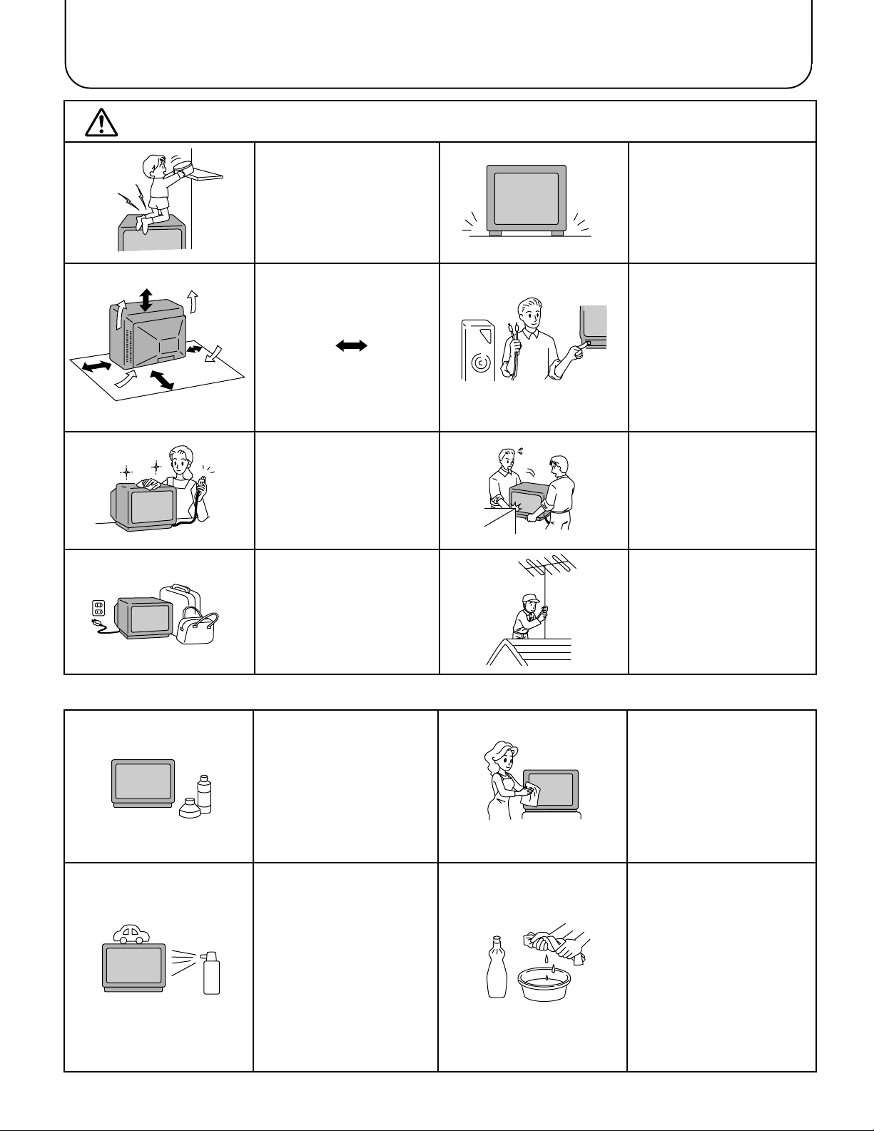
Warnings and Cautions
Warnings
Unplug the power cord in the
event of any malfunction
(screen goes blank, no sound,
odd sounds, smoke or unusual
odours coming from the unit).
Unplug the power cord if
foreign matter or water falls
into the unit, or if the unit is
dropped or the cabinet is
damaged.
DO NOT place any of the
following on the unit:
Flower vases, flower pots,
cups, small metal objects, or
cosmetics containers,
chemicals or water.
DO NOT insert foreign objects
(metal or easily flammable
objects).
DO NOT use this unit near
water. (near a bath tub, etc.)
DO NOT use if the pow er cord
or power plug is damaged, or
if the plug does not fit tightly
into the socket.
DO NOT use at a voltage other
than indicated.
Cautions
TAKE CARE NOT to damage
the power cord.
DO NOT touch the aerial cable
and this unit when there is
lightning.
DO NOT place in humid or
dusty location, or areas
exposed to smoke or steam.
DO NOT place in direct
sunlight and other sources
of direct heat.
DO NOT remove the rear
cover as live parts and High
Voltage components are
accessible when the rear
cover is removed.
DO NOT place in an unstable
location.
DO NOT touch the pow er plug
if your hands are wet.
4
Warnings and Cautions
Caution
DO NOT stand, or place heavy
objects on the unit.
Particular care should be taken
by families with small children.
Adequate ventilation is
essential to prevent failure of
electrical components, we
recommend that a gap of at
least 10cm( ) is left all
around this unit even when it
is placed inside a cabinet or
between shelves.
Before cleaning, unplug the
power plug from the socket.
Unplug the power plug from the
socket if you are not going to
use the unit for an extended
period.
Place in a safe location.
Turn the power “Off” before
connecting other electrical
equipment.
DO NOT jolt the unit.
Ask your sales outlet to install
the aerial.
Cleaning
The unit contains many plastic
parts. For this reason DO NO T
use benzine, thinner or other
chemicals to clean the unit.
DO NOT bring into contact with
insecticide or other volatile
substances.
DO NOT allow the unit to come
into contact for extended
periods with rubber or vinyl
products.
Dust will accumulate on the
picture screen. Please wipe
with a soft cloth from time to
time. If you use a chemically
treated cloth, please be careful
to follow the instructions that
come with the cloth.
Remove dirt and soiling by
wiping with a light cloth.
Even if the unit is heavily soiled,
do not apply cleaner directly to
the unit. Soak a cloth in a
solution of neutral cleanser
thinned with water. Then wring
out the cloth, wipe the unit
clean, and finish by wiping with
a dry cloth.
5
Before Operating This Set
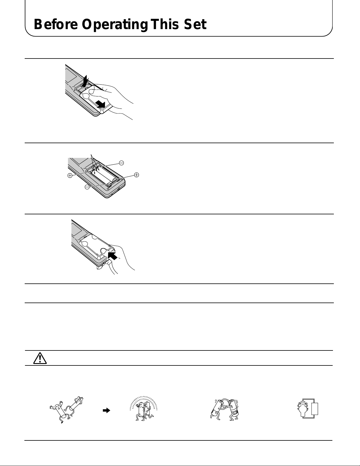
Battery Installation
1
2
Two “R6 (AA)” size
3
Open the cover.
Apply slight downward pressure while pulling tow ards the bottom.
Batteries: Use two “R6 (AA)”size batteries.
Insert the batteries ensuring correct polar ity.
This is identifiable by the “+” and “−” symbols on both the batteries
and inside the battery compartment.
Replace the cover, and slide in reverse until the lock
snaps.
Do not use rechargeable (Ni-Cd) batteries.
They are different in shape and performance and may fail to ensure correct operation.
Battery cautions
The incorrect use of batteries can cause electrolyte leakage which will corrode the Remote Control or cause the
batteries to burst.
Old Batteries New Batteries
Replace both batteries at the same time. Don't mix battery types
(alkaline with carbon zinc, etc.)
Don't Recharge.
6
Before Operating This Set
E
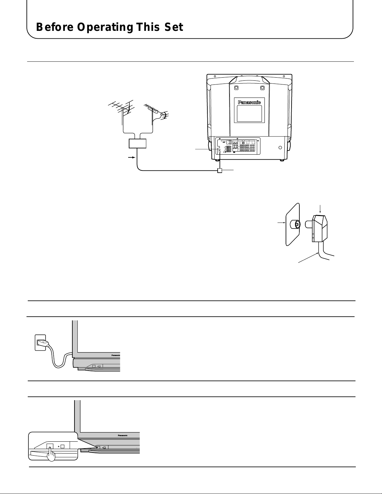
Connecting the Aerial cable to the RF In Terminal
VHF Aerial
Mixer
75 Ohm
UHF Aerial
RF In Terminal
PCM/AC-3
DIGITAL AUDIO INPUT
MONITOR
AUDIO-OUT
OUT
OPTICAL
S-VIDEO
L
L
COAXIAL
REAR
FRONT
VIDEO
R
R
L
FRONT
L
C
W
R
AUDIO
CENTRE SUB WOOFER
L
R
REAR
R
EXT.
Coaxial Cable
Coaxial Aerial Plug
To obtain optimum quality picture and sound, an Aerial, the correct cable (75
Ohm coaxial) and the correct terminating plug are required.
If a communal Aerial system is used, you may require the correct connection
cable and plug between the wall Aerial socket and your television receiver.
Your local Television Service Centre or Dealer may be able to assist you in
obtaining the correct Aerial system for your particular area and accessories
required.
Any matters regarding Aerial installation, upgrading of existing systems or
accessories required, and the costs incurred, are the responsibility of you, the
Customer.
AV1INAV2INAV4
DVD
[Y-Pa-PR]
YY
MONO MONO
IN
DVD
[Y-Pa-PR]
VIDEO
MONO
L
AUDIO
R
RF in
Terminal
Coaxial aerial plug
75 Ohm Coaxial Cable
Connecting the Plug to the Wall outlet
Note:
• Mains plug types vary between countries. The mains plug sho wn at left
may therefore not be the type fitted to your set.
How to turn the Power On
Press the Power switch on Television to turn the set on. (See page 16)
100Hz PROGR
7
Location of Controls
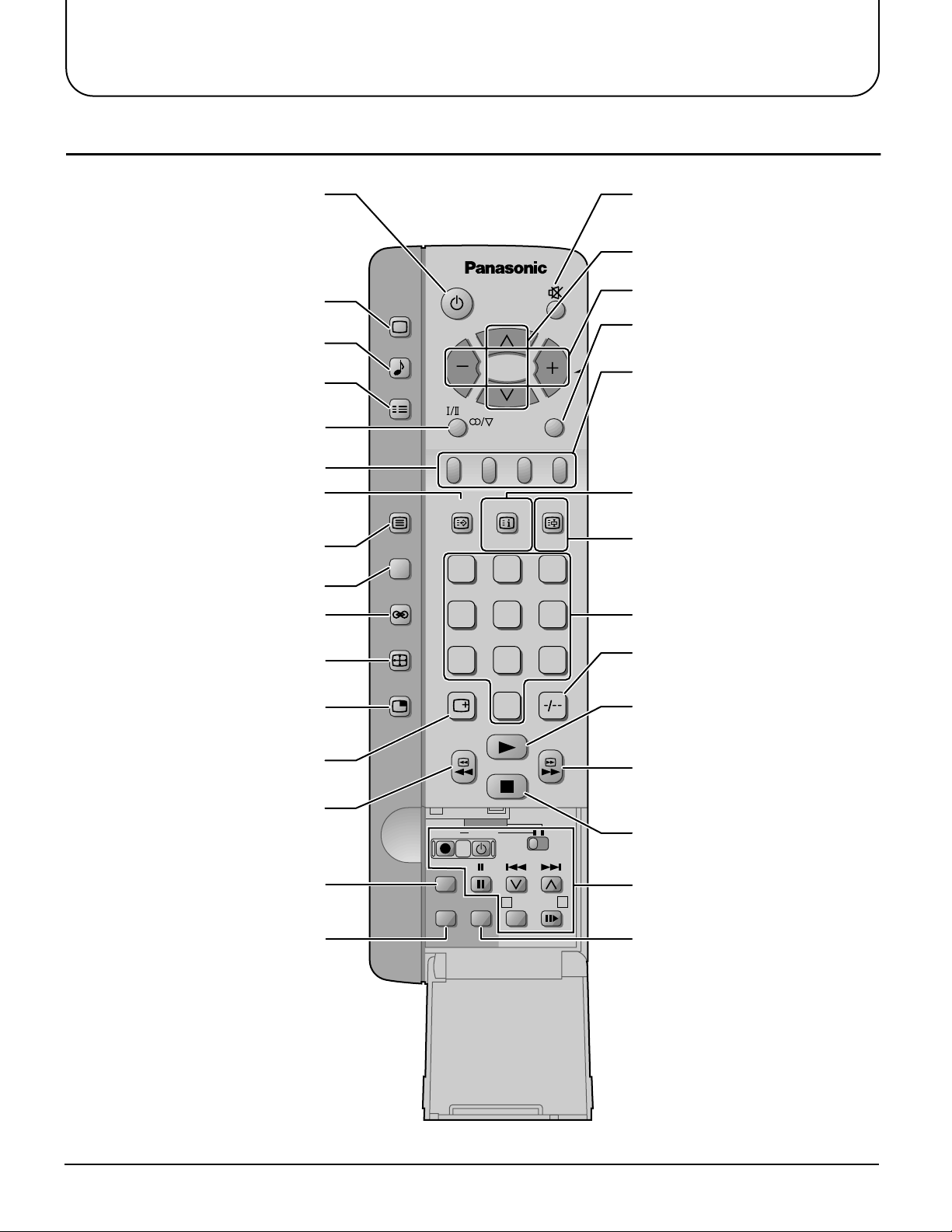
Remote Control
Picture Menu (see page 20)
Sound Menu (see page 22)
Set up Menu (see page 24)
Stereo/Bilingual Sound Selection
(see page 36)
TELE TEXT (see page 38)
TEXT Favourite Page Selection
(see page 39)
PICTURE
SOUND
SET UP
TV/TEXT
F.P. INDEX
TV/AV
HOLD
Sound Mute (see page 17)Power (Stand-by) (see page 16)
Programme Number Up and Down
(see page 16)
Volume Up and Down (see page 17)
TV/AV Mode Selection (see page 17)
Coloured buttons used for
Aspect functions (see page 30)
Teletext functions (see page 38)
AV selection (see page 17)
TEXT Index (see page 39)
/Channel Search (see page 32)
TV/TEXT Selection (see page 32)
100Hz/PROGRE (see page 21)
Surround (see page 22)
Aspect (see page 30)
Picture in Picture Selection
(see page 31)
Recall (see page 17)
VCR/LD/DVD Rewind/Review
(see page 37)
Normalization (see page 21)
Store (see page 17)
100Hz/
PROGRE
SURROUND
ASPECT
MULTI
PIP
1
4
7
LD/DVD
REC VCR
N
STR HELP
?
CH SEARCH
STILL
23
56
89
0
DISC SIDE
A
TEXT hold (see page 32)
/Still (see page 32)
Direct programme Number
Two Digit-programme Number
Selection (see page 16)
VCR/LD/DVD Play (see page 37)
VCR/LD/DVD Fast Forward/Cue
(see page 37)
VCR/LD/DVD Stop (see page 37)
VCR/LD/DVD Control (see page 37)
B
Help (see page 19)
8
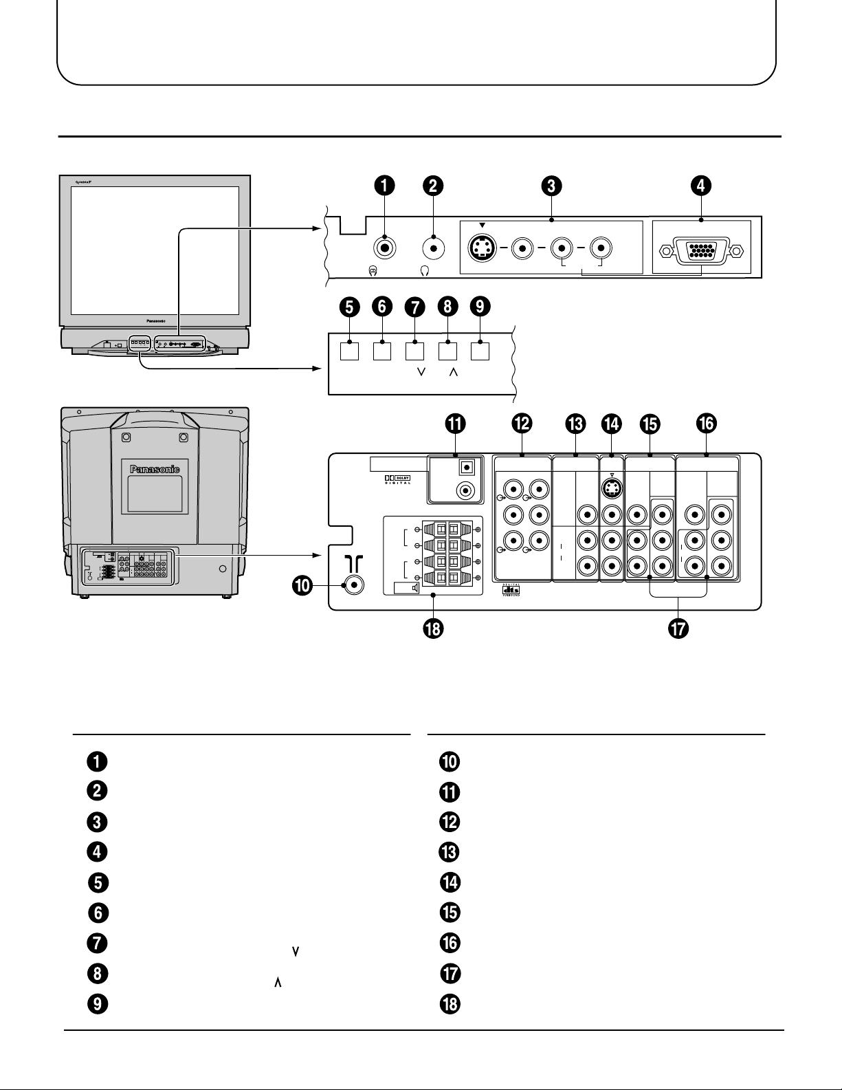
Location of Controls
Controls and Terminals on the TV
PCM/AC-3
DIGITAL AUDIO INPUT
RL/MONO
RGB (31.5kHz)
AV3
IN
AUDIO
STR F –/ +/ TV/AV
Main Sub.
RL/MONO
RGB (31.5kHz)
AV3
IN
AUDIO
S-VIDEO
VIDEO
Main Sub.
S-VIDEO
VIDEO
STR F –/ +/ TV/AV
PCM/AC-3
DIGITAL AUDIO INPUT
FRONT
AV1INAV2INAV4
MONITOR
AUDIO-OUT
IN
OUT
OPTICAL
COAXIAL
L
FRONT
R
L
REAR
R
EXT.
DVD
DVD
S-VIDEO
L
L
[Y-Pa-PR]
[Y-Pa-PR]
VIDEO
REAR
FRONT
YPaY
VIDEO
R
R
Pa
MONO
MONO MONO
L
W
C
L
P
RPR
AUDIO
AUDIO
CENTRE SUB WOOFER
R
R
REAR
EXT.
OPTICAL
COAXIAL
L
R
L
R
AUDIO-OUT
L
FRONT
R
C
CENTRE SUB WOOFER
REAR
MONITOR
S-VIDEO
L
VIDEO
R
L
W
AUDIO
R
OUT
AV1INAV2
IN
MONO MONO
AV4
IN
DVD
[Y-PB-PR]
Y
B
P
P
R
VIDEO
L
AUDIO
R
MONO
DVD
[Y-PB-PR]
Y
B
P
P
R
Item
No.
Function Refer to
Main Headphones Jack 15
Sub Headphones Jack 15
AV3 Input Terminals 10
RGB Input Terminal 14
STR 17
Function 17
Volume Down (−) /
Programme Number
Down ( )
Volume Up (+) /
Programme Number
Up ( )
TV/AV Selection 17
Page
16
16
Item
No.
Function Refer to
Page
Aerial Terminal (RF In Terminal) 7
Digital Audio Input Terminals 12
Audio Output Terminals 12
Monitor Output Terminals 11
AV1 Input Terminals 10
AV2 Input Terminals 10
AV4 Input Terminals 10
•
DVD (Y
•
P
B
PR) Input 11
Speaker Output 13
9

Connections
How to connect the “AV1, 2, 3 or 4” Input Terminals
Connect VCRs and other peripheral equipment
(Super-VHS VCR)
AV1
MONO
IN
S Video
( )
input
AUDIO-OUT
L
L
FRONT
REAR
R
R
C
W
CENTRE SUB WOOFER
MONITOR
OUT
S-VIDEO
VIDEO
L
AUDIO
R
AV1INAV2
MONO MONO
IN
DVD
[Y-PB-PR]
VIDEO
Y
P
B
MONO
L
P
R
AUDIO
R
Audio
OUT
RL
Video
OUT
S-Video
OUT
VIDEO
AUDIO
AV4
IN
DVD
[Y-PB-PR]
Y
P
B
P
R
(VHS VCR)
Audio
OUT
RL
Video
OUT
VIDEO
AUDIO
MONO
AV1
IN
AUDIO-OUT
L
L
FRONT
REAR
R
R
C
W
CENTRE SUB WOOFER
MONITOR
OUT
S-VIDEO
VIDEO
L
AUDIO
R
AV1INAV2
MONO MONO
IN
DVD
[Y-PB-PR]
Y
P
B
P
R
VIDEO
L
AUDIO
R
MONO
AV4
IN
DVD
[Y-PB-PR]
Y
P
B
P
R
Notes:
• When an S-Video cable is connected to the S-Video terminal, the Video input will be automatically s witched off for that
A V mode.
• When a Monaural VCR is used, connect the Monaural Audio cable to the Audio “L” (Left) terminal.
• Select the desired AV input position by pressing the TV/AV button. (Refer to page 17)
• Input 3 is located on the front of the unit.
• The AV2 and AV4 audio input terminals serve as the audio input terminal for both the Video input and for the DVD input
AV2.
10
Connections
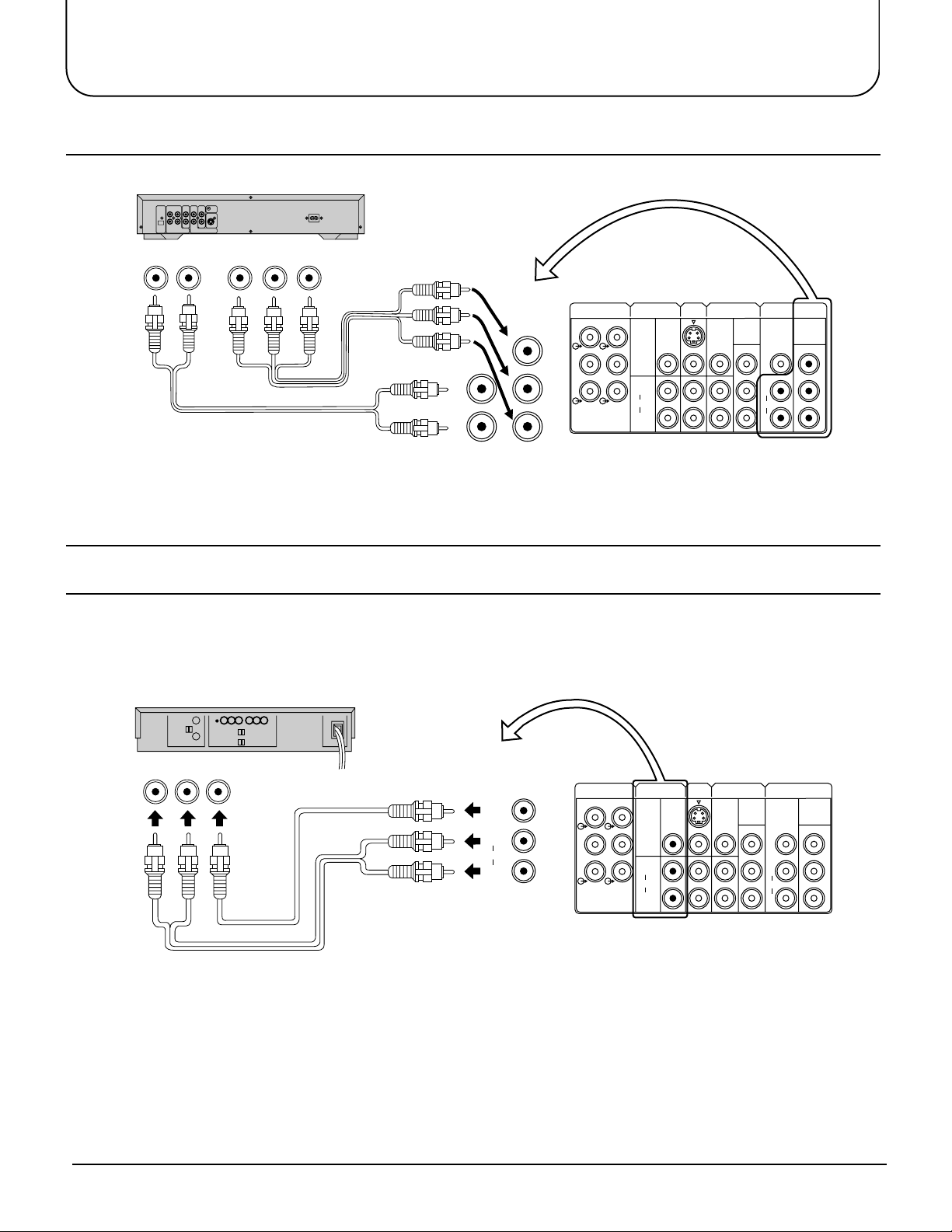
How to connect the DVD Input Terminals
DVD Player
Audio
OUT
LR
DVD(Y•PB•PR) OUT
R
P
PBY
MONO
L
AUDIO
R
OUT
AV1INAV2
MONO MONO
IN
[Y-PB-PR]
Y
B
P
PR PR
DVD
[Y-PB-PR]
Y
P
B
P
R
AUDIO-OUT
L
FRONT
R
C
CENTRE SUB WOOFER
MONITOR
S-VIDEO
L
REAR
VIDEO
R
L
W
AUDIO
R
DVD
L
AUDIO
R
VIDEO
MONO
AV4
IN
DVD
[Y-PB-PR]
Y
B
P
Notes:
• The AV4 audio signal is common for both AV4 and DVD input signal terminals.
• The DVD signal input terminal takes priority over the AV4 video signal input terminal.
• Similar connection are available at the COMPONENT VIDEO input 2 terminal.
How to connect the A V Monitor Output T erminals to other equipment
The “Monitor Out” Terminals output the same signals as main picture on the TV screen and sound from the speaker at
that time, e.g. TV programmes or signals from AV1, AV2, AV3 or AV4 input.
Recording Equipment
(VHS VCR)
MONITOR
Audio Video
RLIN IN
OUT
S-VIDEO
VIDEO
L
AUDIO
R
AUDIO-OUT
L
L
REAR
FRONT
R
R
C
W
CENTRE SUB WOOFER
MONITOR
OUT
S-VIDEO
VIDEO
L
AUDIO
R
AV1INAV2
MONO MONO
DVD
VIDEO
L
AUDIO
R
MONO
AV4
IN
DVD
[Y-PB-PR]
Y
B
P
P
R
IN
[Y-PB-PR]
Y
B
P
P
R
VIDEO
AUDIO
Notes:
• Never connect the same video recorder with both the VIDEO IN and MONITOR OUT terminals on this TV set, as this
could cause incorrect operation.
• The monitor output emits the main picture normal video and audio signals.
• Teletext display on screen will not be output at the MONITOR OUT terminals.
• Even if the television is in picture-in-picture condition, MONITOR OUT ter minals output the same signals as main
picture on the screen and sound from speakers. Sub picture including strobe, still, channel search, etc. will not be output
at the MONITOR OUT terminals.
• The RGB mode signal and DVD signal (Y•P
•
PR) are not output at the MONITOR out terminals.
B
11
Connections
MONITOR
OUT
AUDIO-OUT
L
R
C
L
R
W
FRONT
CENTRE SUB WOOFER
REAR
S-VIDEO
VIDEO
AUDIO
L
R
OPTICAL
COAXIAL
FRONT
REAR
PCM/AC-3
DIGITAL AUDIO INPUT
EXT.
L
R
L
R
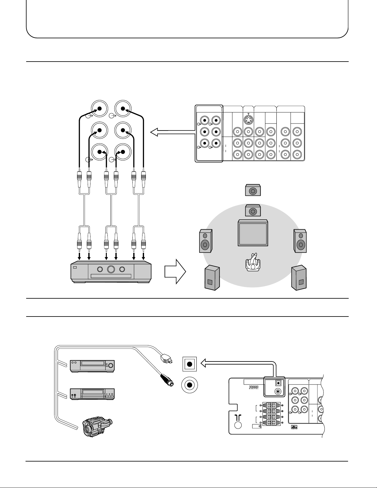
How to connect the AUDIO-OUT terminals
The AUDIO OUT sockets on the rear of the TV allow you to create a custom sound system using an
external amplifier and external speakers.
You may decide, for example, to use an external DTS/Dolby Digital amplifier to connect external front left and right
speakers, rear left and right surround speakers, a centre speaker and a subwoofer (LFE speaker); as shown below.
L
FRONT
R
C
CENTRE SUB WOOFER
L
REAR
R
W
(L) (R)
Front
Centre
Sub
woofer
DTS/Dolby Digital Amplifier
(R) (L)
Rear
Use Phono (RCA)
connectors
(not supplied)
To Speakers
AUDIO-OUT
L
L
FRONT
REAR
R
R
W
C
CENTRE SUB WOOFER
MONITOR
OUT
S-VIDEO
VIDEO
L
AUDIO
R
Centre
speaker
Subwoofer
speaker
Front
left
speaker
Rear left
surround
speaker
AV1INAV2
MONO MONO
IN
DVD
[Y-PB-PR]
VIDEO
Y
B
P
MONO
L
PR PR
AUDIO
R
Front
right
speaker
Rear right
surround
speaker
AV4
IN
DVD
[Y-PB-PR]
Y
B
P
How to connect the DIGITAL AUDIO INPUT
Additional equipment can be connected at the rear of the AV1/AV2/AV3/AV4 and via two digital audio
sockets (for coaxial or optical inputs).
Optical input
Coaxial input
VCR
DVD PLAYER
Note:
• Additional equipment and cables shown are not supplied with this TV set.
12
CAMCORDER
Input to digital audio sockets (use either coaxial or optical input,
only from a DTS/Digital compatible source)
OPTICAL
COAXIAL
Connections
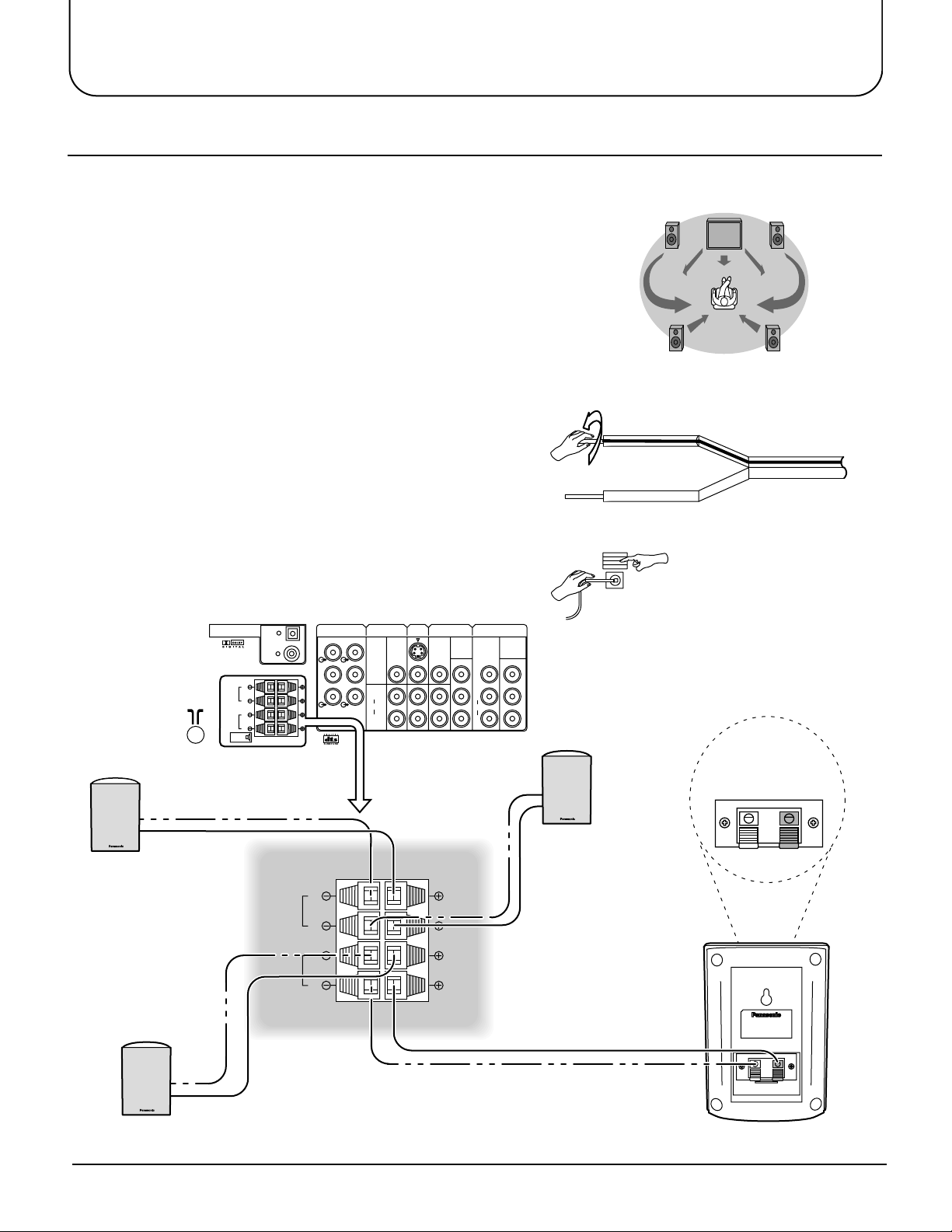
How to connect External Speakers
The external speaker connections (EXT) on the rear of the TV allow you to create your own system using
external speakers.
Connections are provided for front and rear speakers.
External Speaker unit Part No; TY-SP300
Front
left
speaker
You may decide, for example, to connect exter nal
front left and right speakers and rear left and right
surround speakers; as shown here:
Rear left
surround
speaker
The TV must be switched OFF before connecting external equipment.
1 Twist the wire ends before inserting.
Front
right
speaker
Rear right
surround
speaker
2 Inser t into ter minals.
Ensure that bare speaker wires are not touching.
Front
left speaker
PCM/AC-3
DIGITAL AUDIO INPUT
L
FRONT
R
L
REAR
R
EXT.
OPTICAL
COAXIAL
FRONT
REAR
AUDIO-OUT
L
FRONT
R
C
CENTRE SUB WOOFER
L
R
L
R
L
REAR
R
W
MONITOR
S-VIDEO
VIDEO
L
AUDIO
R
OUT
AV1INAV2
MONO MONO
Press lever
Insert wire
IN
AV4
IN
DVD
[Y-PB-PR]
Y
B
P
P
R
L
AUDIO
R
VIDEO
MONO
DVD
[Y-PB-PR]
Y
B
P
P
R
Front
right speaker
Speaker
Black (–) Red (+)
Rear left
surround speaker
Rear right
surround speaker
13

Connections
Pin No.
Signal Name
Pin No.
Signal Name
Pin No.
Signal Name
1
2
3
4
5
R
G
B
GND(Ground
)
GND(Ground
)
GND(Ground
)
NC
HD/SYNC
VD
NC
(
not connected
)
GND(Ground
)
GND(Ground
)
GND(Ground
)
NC
(
not connected
)
GND(Ground
)
6
7
8
9
10
11
12
13
14
15
How to connect the RGB Input Terminals
Main Sub.
S-VIDEO
VIDEO
RL/MONO
AUDIO
AV3
IN
RGB (31.5kHz)
COMPUTER
Conversion adapter (if necessary)
D-SUB 15P
RGB
PC cable
Notes:
• This unit can be connected to PCs with 640 ✕ 480 (31.5 kHz / 60 Hz) or 640 ✕ 400 (31.5 kHz / 70 Hz) pixel.
• In some cases other PCs may not work with this TV set.
• There is no audio signal in RGB input.
• The sound of the RGB mode is combined with the Audio signal of AV3.
• Some PC models cannot be connected to the TV set.
• A commercially sold adapter is required to use the RGB cable (D-sub 15P) to connect a
PC-98 series computer (which has a D-sub 15P terminal) or a Macintosh computer to the TV set.
• There is no need to use an adapter for computers with DOS/V compatible D-sub 15P terminal.
Signal Names for D-sub 15P Connector
5
10
9
15 141312
1
8
6
7
11
2
4
3
Pin Layout for RGB Input
Terminal
14
 Loading...