


ORDER No. SM-04020
Service Manual
Colour Television
Z-M3P Chassis
TX-28CK2P
SPECIFICATIONS
Power Source: 220 - 240V A.C., 50Hz Video/Audio Terminals:
Power Consumption: 78W AV1 IN Video (21 pin) 1V p-p 75Ω
Audio (21 pin) 500mV rms 10KΩ
Stand-by Power Consumption: 1W RGB (21 pin)
Audio (RCA x 2) 500mV rms 10KΩ
Video (RCA x 1) 1V p-p 75Ω
Receiving System: PAL B/G, D/K, 525/60
SECAM B/G, D/K AV1 OUT Video (21 pin)
M.NTSC Audio (21 pin) 500mV rms 10KΩ
NTSC (AV only)
Receiving Channels: VHF E2-E12 Picture Tube: A66QEW13X38 66cm
UHF E21-E68
CATV S1-S10 (M1-M10) High Voltage: 29 ± 1kV
CATV S11-S20 (U1-U10)
CATV S21-S41 (HYPERBAND) Audio Output: 20W
(Music Power) 8Ω
Headphones: 8Ω
Intermediate Frequency: Video 38.9MHz, 34MHz 3.5mm
Video/Audio
Audio 32.9MHz, 33.16MHz, 33.4MHz Accessories: Remote Control
40.4MHz, 32.4MHz (A2 STEREO) 2 x R6 (UM3) Batteries
33.05MHz, 34.05MHz (NICAM)
Impedance
1V p-p 75Ω
Colour 34.47MHz (PAL) Dimensions:
34.5MHz, 34.65MHz (SECAM) Height: 571.5mm
Width: 650.0mm
Depth: 500.5mm
Net Weight: 31kg
NOTE:
Specifications are subject to change witho ut notic e.
Weights and dimensions shown are approx imate .
CONTENTS
SAFETY PRECAUTIONS.........................................................................................................................................................2
SERVICE HINTS.......................................................................................................................................................................3
ALIGNMENT PROCEDURE.....................................................................................................................................................4
WAVEFORMS...........................................................................................................................................................................5
BLOCK DIAGRAM....................................................................................................................................................................7
PARTS LOCATION...................................................................................................................................................................8
REPLACEMENT PARTS LIST..................................................................................................................................................9
SCHEMATIC DIAGRAMS.......................................................................................................................................................15
PCB CONDUCTOR VIEWS....................................................................................................................................................23
SAFETY PRECAUTIONS
GENERAL GUIDE LINES
1. It is advisable to insert an isolation transformer in the
a.c. supply before servicing a hot chassis.
2. When servicing, observe the original lead dress in the
high voltage circuits. If a short circuit is found, replace
all parts that have been overheated or damaged by
the short circuit.
3. After servicing, see that all the protective devices
such as insulation barriers, insulation papers, shields
and isolation R-C combinations are correctly
installed.
4. When the receiver is not being used for a long period
of time, unplug the power cord from the a.c. outlet.
5. Potentials as high as 30kV are present when this
receiver is in operation. Operation of the receiver
without the rear cover involves the danger of a shock
hazard from the receiver power supply. Servicing
should not be attempted by anyone who is not
familiar with the precautions necessary when working
on high voltage equipment. Always discharge the
anode of the tube.
6. After servicing make the following leakage current
checks to prevent the customer from being exposed
to shock hazard.
LEAKAGE CURRENT COLD CHECK
1. Unplug the a.c. cord and connect a jumper between
the two prongs of the plug.
2. Turn on the receiver’s power switch.
3. Measure the resistance value with an ohmmeter,
between the jumpered a.c. plug and each exposed
metallic cabinet part on the receiver, such as screw
heads, aerials, connectors, control shafts etc. When
the exposed metallic part has a return path to the
chassis, the reading should be between 4M ohm and
20M ohm. When the exposed metal does not have a
return path to the chassis, the reading must be
infinite.
LEAKAGE CURRENT HOT CHECK
1. Plug the a.c. cord directly into the a.c. outlet. Do not
use an isolation transformer for this check.
2. Connect a 2kΩ 10W resistor in series with an
exposed metallic part on the receiver and an earth,
such as a water pipe.
3. Use an a.c. voltmeter with high impedance to
measure the potential across the resistor.
4. Check each exposed metallic part and check the
voltage at each point.
5. Reverse the a.c. plug at the outlet and repeat each of
the above measurements.
6. The potential at any point should not exceed
1,4Vrms. In case a measurement is outside the limits
specified, there is a possibility of a shock hazard, and
the receiver should be repaired and rechecked before
it is returned to the customer.
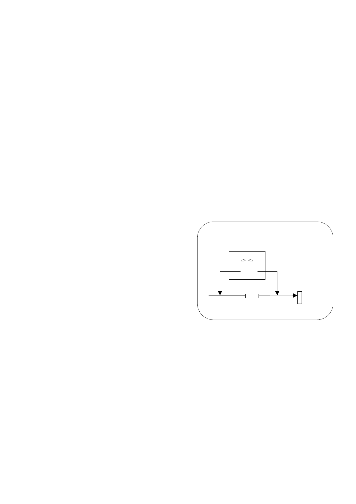
HOT CHECK CIRCUIT
a.c. VOLTMETER
ΩΩΩΩ
2k
10 Watts
TO INSTRUMENT'S EXPOSED
METALLIC PARTS
Fig. 1.
X-RADIATION WARNING
1. The potential sources of X-Radiation in TV sets are
the high voltage section and the picture tube.
2. When using a picture tube test jig for service, ensure
that the jig is capable of handling 30kV without
causing X-Radiation.
NOTE: It is important to use an accurate periodically
calibrated high voltage meter.
1. Set the brightness to minimum.
2. Measure the high voltage. The meter should indicate.
29kV ± 1kV.
If the meter indication is out of tolerance, immediate
service and correction is required to prevent the
possibility of premature component failure.
3. To prevent any X-Radiation possibility, it is essential
to use the specified tube.
WATER PIPE
(
EARTH)
2
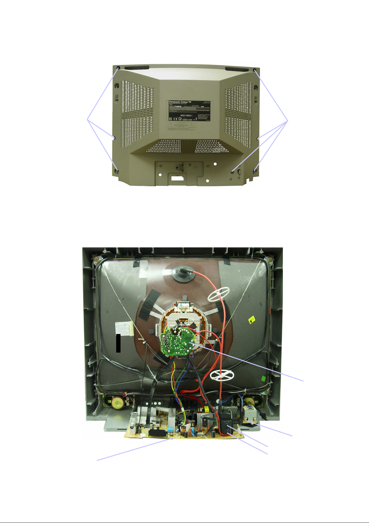
SERVICE HINTS
How to remove the rear cover
1. Remove the 7 screws as shown in Fig.2.
SCREWS
Fig. 2.
LOCATION OF CONTROLS
CRT Board
Main Board
Filter Board
Focus
Screen
3
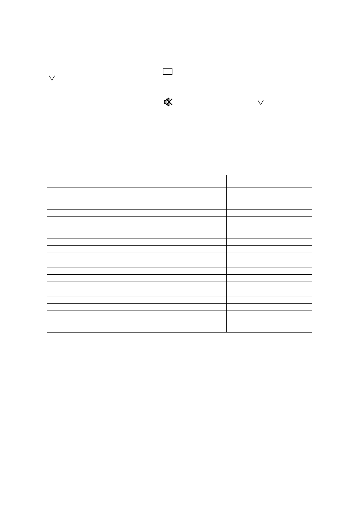
ALIGNMENT PROCEDURE AND OPTION SETTING
Self Check Mode
To enter self check mode, set the programme position to Channel 99.
Set sharpness to a minimum, press the status button ( ) on the remote contol whilst simultaneously pressing the down
button ( ) at the front of the set. This should bring the set into self check mode.
Entering SERVICE mode
Whilst in self check mode, press the mute remote key ( ) and local down button on the set ( ) simultaneously. The user
must make sure that Sharpness is set to a minimum and that the programme position is set to Channel 99 as well. This
should bring the user to service mode1. Scroll through the service items using the cursor up and down keys and adjust
accordingly using the - /+ keys on the r emote.
Service mode navigation
Up /Down remote keys :scroll through the service items available.
-/+ remote keys :Decrement/Increment the values within range.
TV/AV :Store the current data.
ORDER FUNCTIONS AND SETTINGS VALUES (NOMINAL VALUES)
1
2
3
4
5
6
7
8
9
10
11
12
13
14
15
16
17
18
19
20
Cut Off Alignment UG2
Vertical Slope V-Slo
Vertical Positio n V-Pos
Vertical Amplitud e V-Amp
Horizontal Position H-Ctr
Horizontal Parabola H-Par
Horizontal Bow H-Bow
Red Colour Cut R-Cut
Green Colour Cut G-Cut
Red Colour Drive R-Drv
Green Colour Drive G-Drv
Blue Colour Drive B-Drv
RF Automatic Gain Control AGC
Sub Colour S-Col
Sub Brightness S-Bri
East/West Width (Horizontal Amplitude) EW-WD
East/West Parabola EW-PR
East/West Upper Corner EW-UC
East/West Lower Corner EW-LC
East/West Trapezium EW-TP
+
TEST
033
005
045
039
030
021
037
031
063
048
038
035
011
040
017
039
044
042
034
Cut Off UG2 alignment: Adjust it on AV mode.
Set condition is in AV mode without signal.
Place the set into an Ageing Test for more than 15 minutes.
Adjust the unit to the following settings.
R-Cut=32, G-Cut=32, R-Drv=42, G-Drv=42, B-Drv=42.
Press the G2 button on the service remote.
Adjust the Screen Volum e on the FBT until the indicator on the set will be lit.
White Balance: Adjust this after performing CUT OFF UG2 alignment.
Place the set into an ageing test for approximately 15 minutes.
Generate a gray scale pattern from a Pattern Generator.
Set the colour balance to normal position.
Press the FACTORY button on the service remote.
Adjust accordingly using +/- button on the service remote to whiten the settings of
R-Cut, G-Cut, R-Drv and G-Drv at each section equally.B-Drv step number
however should be fixed at 42.
4
MICON/CHROMA
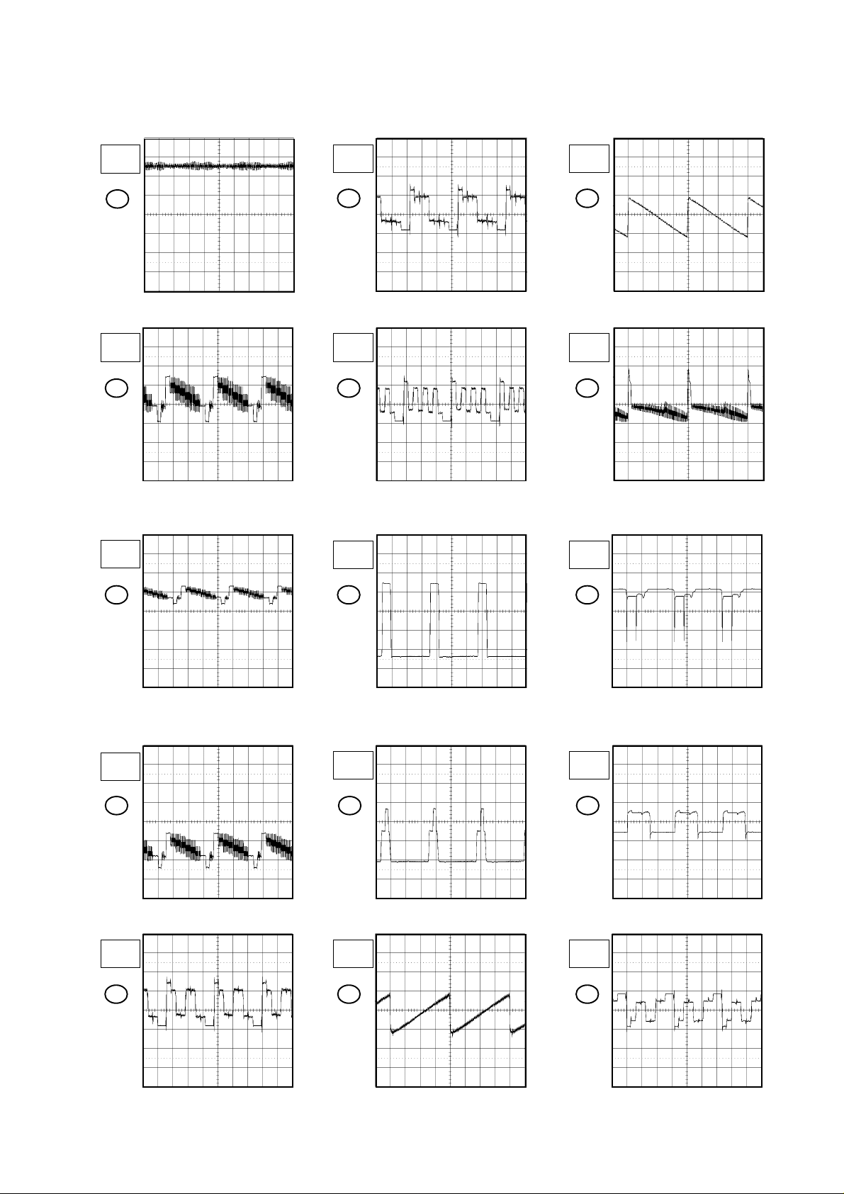
WAVEFORMS
20µs
1.00V
1
20µs
1.00V
2
20µs
1.00V
20µs
1.00V
5ms
0.5V
6 17
20µs
1.00V
7
20µs
2.00V
5ms
10.0V
18
20µs
5.0V
3
20µs
1.00V
4
20µs
1.00V
5
9
20µs
2.00V
10
DEFLECTION/CRT
5ms
0.5V
16
19
20µs
0.5V
20
20µs
50V
21
The following waveforms were measured at the point of the corresponding
NOTE:
balloon number in the schematic diagram.
H-1
WAVEFORMS
20µs
50V
22
20µs
50V
23
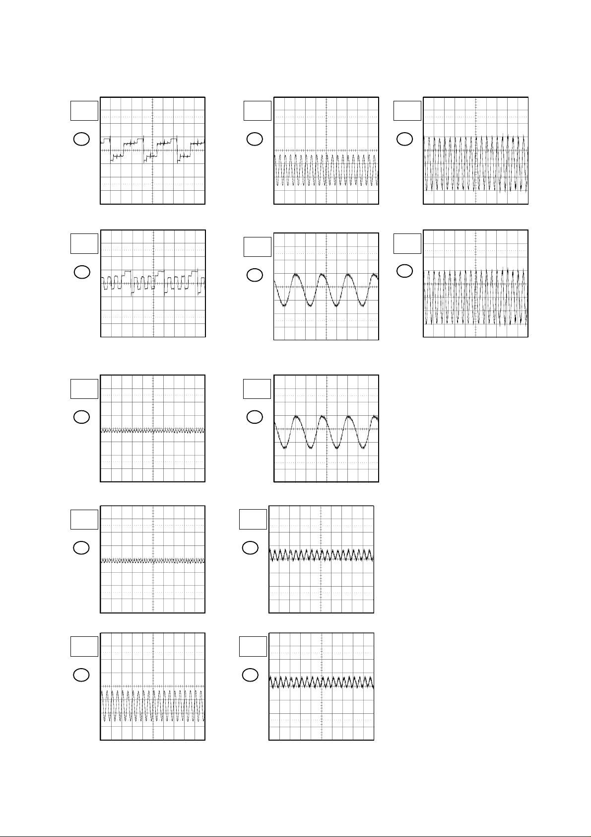
SOUND AMP
2ms
0.50V
0.2ms
5.0V
45
STEREO
0.2ms
0.50V
49
0.2ms
0.50V
0.2ms
200mV
57
0.2ms
200mV
58
42
2ms
0.50V
43
0.2ms
5.0V
44
50
0.2ms
100mV
51
0.2ms
100mV
52
The following waveforms were measured at the point of the corresponding
NOTE:
balloon number in the schematic diagram.
H-2

J702
HEADPHONE JACK
SP351
SPEAKER
J703
E-2
CRT
V801
J704
2
2
J705
2
7
3
2
7
SOUND AMP IC
IC1001 AN5277
1
5
127
11
5
2
10
FRONT VIDEO
1
J701
19
Q607
BUFFER
3
FRONT AUDIO L
20
8
16
8
3
2
68
11
9
1
FRONT AUDIO R
6
2
7
11
15
7
VIDEO AMP IC
5
IC801 TDA6108JF
10
F
DY
PROTECT
Q403~Q406
FB401
1
10
F
S
HV
7
9
2
1
40
11
Q606
42CVBS/Yin
BUFFER
38
45
OS101
8
48
47
43
64
34
50
51
52
53
P.CON+5V
3
P.CON+8V
3
IR
B_IN
CVBSin
MUTE
IF_VO
S/SW
F_BLANK
G_IN
R_IN 46
C_IN
SAND
I_BLACK
R_OUT
G_OUT
B_OUT
1
5V REG. IC
IC501 KIA7805API
8V REG. IC
IC502 KIA7808API
1
MICON/CHROMA IC
IC101 TDA9365V5
BLOCK DIAGRAM
6 KEY_LED
X_TAL58X_TAL
59
X101
EEPROM IC
SCL
2
12MHz
6
IC199
5
S-24C16AFJA-TB-01
SDA
3
AGC
27
CF601
IF1
IF2
24
23
FILTER
VIF SAW
Q609
VIF PRE.AMP
SIFN 1
28
FILTER
SIF SAW
CF602
IF AMP
Q612
SIFN 2
PROTECTION
36
29
BCL
49
AC IN
H.OUTPUT
Q401
H.DRIVE
Q402
V+
V-
22
21
QSS_OUT
H_OUT
35
33
ALV/EW
20
PELAY
RY501
CD501
5
1
7
V.OUTPUT IC
IC401 LA78041
D501~D504
T501
H.CONTROL
Q453~Q455
11
18
14
17
8
5
POWER
Q511
SW
Q502
5
41
1
RESET IC
IC901 R3111N311A/C-TR
UP
TU001
TV/AV
DOWN
FUNCTION
STR
11
21
3
27
28
FEED BACK
IC506
1
4
7
5
T502
6
2
67
D529, D532
D533, D534
36
56
37
57
A2/NICAM/DOLBY IC
IC902 MSP3415G-QA-B8-V3
8
AT3.5V
AT+5.6V
H. CONTROL IC
20V REG.IC
6
IC451 TEA2031A
1
3
IC452 KIA78L20BP-AT
H.DRV+B
PS2561AL1-1-V(W)
F.BACK SW
Q507
+B ADJ.
VR501
E-1
10
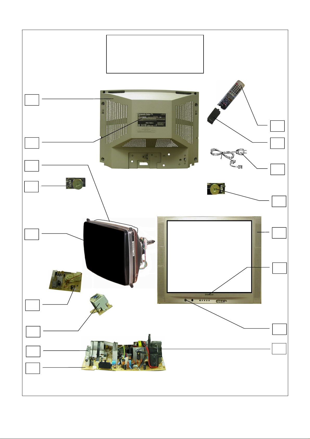
PARTS LOCATION
NOTE:
The numbers on the exploded view below
refer to the mechanical section of the
Replacement Parts List.
This diagram is used for representative
purposes only.
12
14
11
3
6
16
1
14
2
4
8
15
7
9
5
13
8