

Panasonic TX-32LX1X, TX-32LX1M, TX-32LX1A, TX-32LX1T, TC-32LX1H Service manual
...
TX-32LX1X
A
A
A
r
TX-32LX1M
TX-32LX1A
TX-32LX1T
TC-32LX1H
TC-32LX1DJ
TX-26LX1X
ORDER NO. ITD0406016C3
LCD TV
TX-26LX1M
TX-26LX1A
TX-26LX1T
TC-26LX1H
LH18 Chassis
Specifications
PowerSource
PowerConsumption
LCD Wide XGA (1,280 × 768 pixels)
Screen Size 566.4mm (W) x 339.8mm (H) (26 inch model) 687.4mm (W) x 412.4mm (H) (32 inch model)
Sound
Speake
Audio Output 20W (10W + 10W)
Headphones M3 (3.5mm) Jack x 1
C 100-127/200-240V, 50/60Hz
verage use
100-127V: 130W (26 inch model)
200-240V: 129W (26 inch model)
Standby condition: 1.8W
Power Off: 1.5W
15 : 9 aspect ratio LCD panel
Ø8cm × 2pcs, Ø4cm × 2pcs, 8W
verage use
100-127V: 165W (32 inch model)
200-240V: 163W (32 inch model)
© 2004 Matsushita Electric Industrial Co., Ltd. All
rights reserved. Unauthorized copying and
distribution is a violation of law.
V
V
r
r
A
A
r
A
Y
A
TX-32LX1X / TX-32LX1M / TX-32LX1A / TX-32LX1T / TC-32LX1H / TC-32LX1DJ / TX-26LX1X / TX-26LX1M / TX-26LX1A / TX-26LX1T / TC-26LX1H
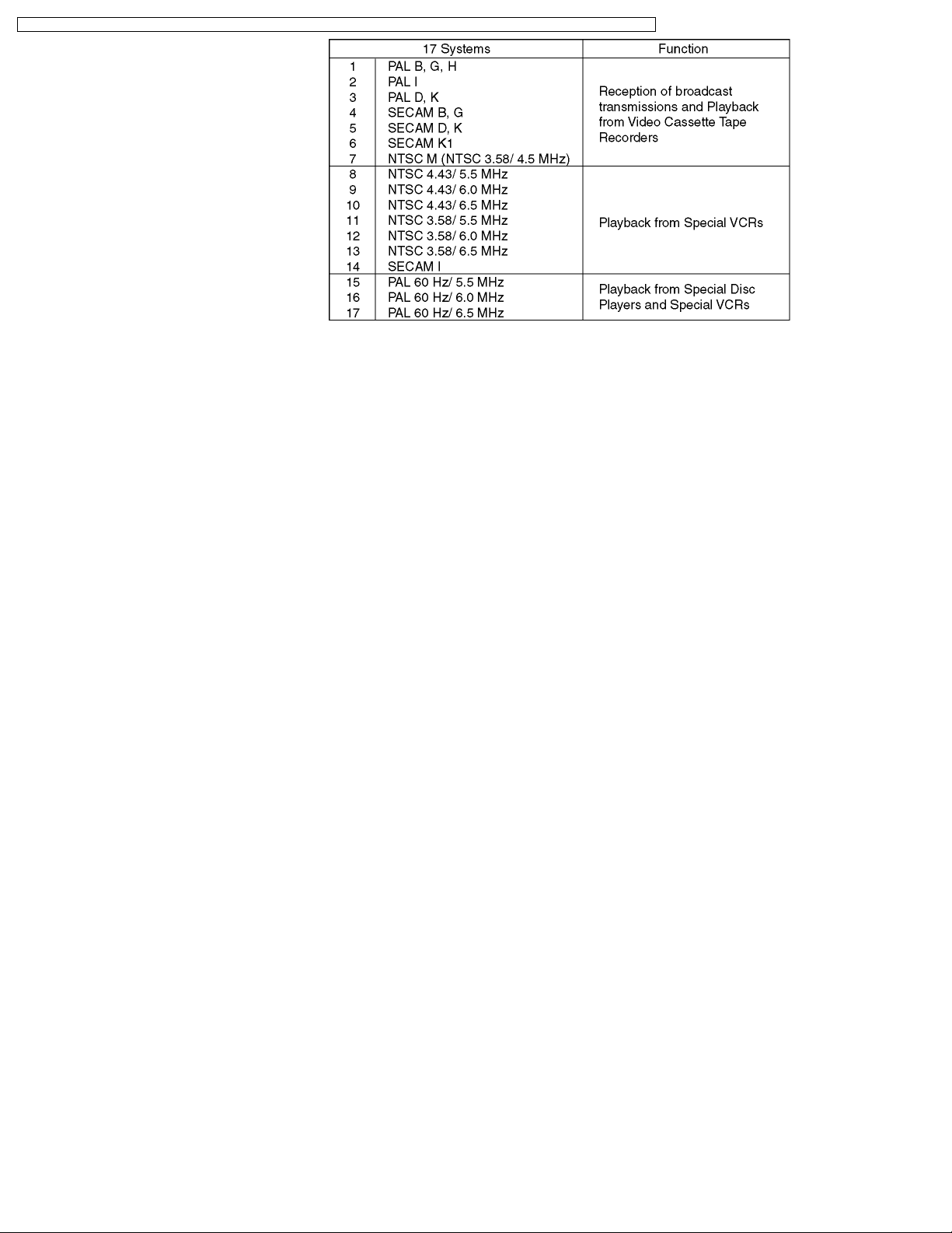
Receiving Systems/Band name
Receiving Channels RegularTV
HF BAND 2-12 (PAL/SECAM B, K1)
0-12 (PAL B AUST.)
1-9 (PAL B N.Z.)
1-12 (PAL/ SECAM D)
1-12 (NTSC M Japan)
2-13 (NTSC M USA)
UHF BAND 21-69 (PAL G, H, I/ SECAM G, K, K1)
28-69 (PAL B AUST.)
13-57 (PAL D, K)
13-62 (NTSC M Japan)
14-69 (NTSC M USA)
CAT
S1-S20 (OSCAR)
1-125 (USA CATV)
C13-C49 (JAPAN)
S21-S41 (HYPER)
Z1-Z37 (CHINA)
5A, 9A (AUST.)
Aerial-Rea
UHF/VHF
Operating Conditions Temperature: 5°C-35°C
Humidity: 5%-90% RH (non-condensing)
Connection Terminals
AV1/2-Rea
VIDEO (RCA Pin Type) 1.0Vp-p (75W)
S-VIDEO (MINI DIN 4-pin) Y: 1.0Vp-p (75W) C: 0.286Vp-p (75W)
UDIO L-R (RCA Pin Type × 2) 0.5Vrms
AV3-Front VIDEO (RCA Pin Type) 1.0Vp-p (75W)
S-VIDEO (MINI DIN 4-pin) Y: 1.0Vp-p (75W) C: 0.286Vp-p (75W)
UDIO L-R (RCA Pin Type × 2) 0.5Vrms
AV4-Rea
VIDEO (RCA Pin Type) 1.0Vp-p (75W)
UDIO L-R (RCA Pin Type × 2) 0.5Vrms
1.0Vp-p (including synchronization)
PB/P
R
±0.35Vp-p
HD/VD 1.0-5.0Vp-p (high impedance) (TTL level)
MONITOR OUT VIDEO (RCA Pin Type) 1.0Vp-p (75W)
UDIO L-R (RCA Pin Type × 2) 0.5Vrms
Others SD Card slot × 1, PC Card slot × 1
Dimensions (W x H x D)
Including TV Stand 844mm x 571.8mm x 321mm (26 inch model) 1,000mm x 651.7mm x 321mm (32 inch model)
TV Set Only 844mm x 478mm x 137mm (26 inch model) 1,000mm x 558mm x 137mm (32 inch model)
Weight 22.5kg Net (26 inch model) 27kg Net (32 inch model)
2
TX-32LX1X / TX-32LX1M / TX-32LX1A / TX-32LX1T / TC-32LX1H / TC-32LX1DJ / TX-26LX1X / TX-26LX1M / TX-26LX1A / TX-26LX1T / TC-26LX1H
Note:
Design and Specifications are subject to change without notice. Weight and Dimensions shown are approximate.
CONTENTS
Page Page
1 Safety Precautions 4
1.1. General Guidelines
2 Prevention of Electro Static Discharge (ESD) to
Electrostatically Sensitive (ES) Devices
3 Self Check
4 Chasis Board Layout
5 Before servicing
5.1. Kind and location of the flexible cable
5.2. How to remove the connector
6 Disassembly for Service
6.1. Stand ass´y
6.2. Rear cover
6.3. Rear AV bracket ass´y
6.4. Rear metal frame
6.5. Speaker box (left and right)
6.6. TA-Board
6.7. A-Board
6.8. IC heat shink
6.9. AP-Board
6.10. DG-Board
6.11. H-Board
6.12. P-Board
6.13. Front bracket
6.14. K-Board
6.15. JG-Board
6.16. V-Board
6.17. Main chassis
6.18. LCD panel
7 Location of Lead Wiring
8 Service Mode Function
8.1. How to enter SERVICE 1
8.2. How to enter SERVICE 2
8.3. Option Description
8.4. Option Code Setting (26 inch model)
8.5. Option Code Setting (32 inch model)
9 Adjustment method
9.1. Video Signal Level Adjustment
9.2. WB Adjustment
10 Conductor Views
10
10
10
10
11
11
11
11
11
12
12
12
12
13
13
13
13
13
14
15
16
16
16
18
20
20
21
21
21
23
4
5
6
7
8
8
9
10.1. P-Board
10.2. AP-Board
10.3. A-Board
10.4. DG-Board
10.5. H and TA-Board
10.6. JG-Board
10.7. K and V-Board
11 Block and Schematic Diagrams
11.1. Schematic Diagram Notes
11.2. Main Block Diagram
11.3. Signal Block Diagram
11.4. Power Block Diagram
11.5. P-Board Schematic Diagram (TC-32LX1DJ, TX26/32LX1T)
11.6. P-Board Schematic Diagram (TC-26/32LX1H, TX26/32LX1A/M/X)
11.7. AP-Board (1 of 2) Schematic Diagram
11.8. AP-Board (2 of 2) Schematic Diagram
11.9. A-Board (1 of 4) Schematic Diagram
11.10. A-Board (2 of 4) Schematic Diagram
11.11. A-Board (3 of 4) Schematic Diagram
11.12. A-Board (4 of 4) Schematic Diagram
11.13. DG-Board (1 of 6) Schematic Diagram
11.14. DG-Board (2 of 6) Schematic Diagram
11.15. DG-Board (3 of 6) Schematic Diagram
11.16. DG-Board (4 of 6) Schematic Diagram
11.17. DG-Board (5 of 6) Schematic Diagram
11.18. DG-Board (6 of 6) Schematic Diagram
11.19. H-Board Schematic Diagram
11.20. JG-Board (1 of 2) Schematic Diagram
11.21. JG-Board (2 of 2) Schematic Diagram
11.22. K, TA and V-Board Schematic Diagram
12 Parts Location & Mech anica l Replacement Parts List
12.1. Parts Location
12.2. Packing Exploded View
12.3. Mechanical Replacement Parts List
13 Repla ceme nt Parts List
13.1. Replacement Parts List Notes
13.2. Electrical Replacement Parts List
23
27
29
32
35
37
39
41
41
42
43
46
48
49
50
51
52
53
54
55
56
57
58
59
60
61
62
63
64
65
67
67
69
70
72
72
73
3
TX-32LX1X / TX-32LX1M / TX-32LX1A / TX-32LX1T / TC-32LX1H / TC-32LX1DJ / TX-26LX1X / TX-26LX1M / TX-26LX1A / TX-26LX1T / TC-26LX1H
1 Safety Precautions
1.1. General Guidelines
1. When servicing, observe the original lead dress. If a short circuit is found, replace all parts which have been overheated or
damaged by the short circuit.
2. After servicing, see to it that all the protective devices such as insulation barriers, insulation papers shields are properly
installed.
3. After servicing, make the following leakage current checks to prevent the customer from being exposed to shock hazards.
1.1.1. Leakage Current Cold Check
1. Unplug the AC cord and connect a jumper between the two
prongs on the plug.
2. Measure the resistance value, with an ohmmeter, between
the jumpered AC plug and each exposed metallic cabinet
part on the equipment such as screwheads, connectors,
control shafts, etc. When the exposed metallic part has a
return path to the chassis, the reading should be between
1MW and 5.2MW.
When the exposed metal does not have a return path to
the chassis, the reading must be
Figure 1
.
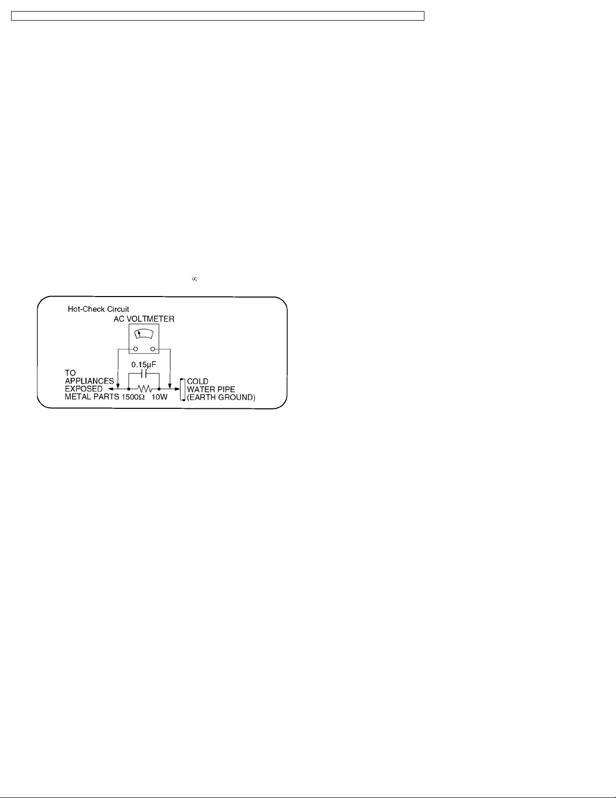
1.1.2. Leakage Current Hot Check (See
Figure 1.)
1. Plug the AC cord directly into the AC outlet. Do not use an
isolation transformer for this check.
2. Connect a 1.5kW, 10 watts resistor, in parallel with a 0.15µF
capacitors, between each exposed metallic part on the set
and a good earth ground such as a water pipe, as shown in
Figure 1.
3. Use an AC voltmeter, with 1000 ohms/volt or more
sensitivity, to measure the potential across the resistor.
4. Check each exposed metallic part, and measure the
voltage at each point.
5. Reverse the ACplug in theAC outlet andrepeat each of the
above measurements.
6. The potential at any point should not exceed 0.75 volts
RMS. A leakage current tester (Simpson Model 229 or
equivalent) may be used to make the hot checks, leakage
current must not exceed 1/2 milliamp. In case a
measurement is outside of the limits specified, there is a
possibility of a shock hazard, and the equipment should be
repaired and rechecked before it is returned to the
customer.
4
TX-32LX1X / TX-32LX1M / TX-32LX1A / TX-32LX1T / TC-32LX1H / TC-32LX1DJ / TX-26LX1X / TX-26LX1M / TX-26LX1A / TX-26LX1T / TC-26LX1H
2 Prevention of Electro Static Discharge (ESD) to
Electrostatically Sensitive (ES) Devices
Some semiconductor (solid state) devices can be damaged easily by static electricity. Such components commonly are called
Electrostatically Sensitive (ES) Devices. Examples of typical ES devices are integrated circuits and some field-effect transistors and
semiconductor "chip" components. The following techniques should be used to help reduce the incidence of component damage
caused by electro static discharge (ESD).
1. Immediately before handling any semiconductor component or semiconductor-equipped assembly, drain off any ESD on your
body by touching a known earth ground. Alternatively, obtain and wear a commercially available discharging ESD wrist strap,
which should be removed for potential shock reasons prior to applying power to the unit under test.
2. After removing an electrical assembly equipped with ES devices, place the assembly on a conductive surface such as alminum
foil, to prevent electrostatic charge buildup or exposure of the assembly.
3. Use only a grounded-tip soldering iron to solder or unsolder ES devices.
4. Use only an anti-static solder removal device. Some solder removal devices not classified as "anti-static (ESD protected)" can
generate electrical charge sufficient to damage ES devices.
5. Do not use freon-propelled chemicals. These can generate electrical charges sufficient to damage ES devices.
6. Do not remove a replacement ES device from its protective package until immediately before you are ready to install it. (Most
replacement ES devices are packaged with leads electrically shorted together by conductive foam, alminum foil or comparable
conductive material).
7. Immediately before removing the protective material from the leads of a replacement ES device, touch the protective material
to the chassis or circuit assembly into which the device will be installed.
Caution
Be sure no power is applied to the chassis or circuit, and observe all other safety precautions.
8. Minimize bodily motions when handling unpackaged replacement ES devices. (Otherwise hamless motion such as the brushing
together of your clothes fabric or the lifting of your foot from a carpeted floor can generate static electricity (ESD) sufficient to
damage an ES device).
5
TX-32LX1X / TX-32LX1M / TX-32LX1A / TX-32LX1T / TC-32LX1H / TC-32LX1DJ / TX-26LX1X / TX-26LX1M / TX-26LX1A / TX-26LX1T / TC-26LX1H
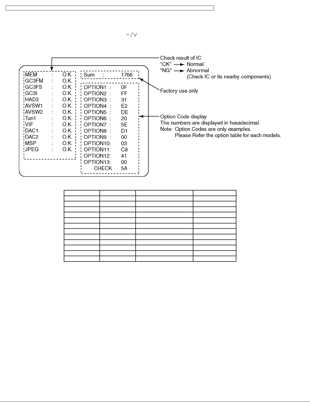
3 Self Check
1. Self-Check is used to automatically check the bus lines and hexadecimal code of the TV set.
2. To enter the Self -Check mode press the Down (
on the remote controller, and the screen will show :
3. Turn off the TV to reset JPEG Viewer circuit after SELF-CHECK.
) button on the TV set, at the same time pressing the Off-Timer button
If the CCU ports have been checked and found to be incorrect or not located then “--” will appear in place of “O.K.”.
Display Ref. No. Description P.C.B.
MEM IC1107 Memory DG-Board
GC3FM IC4017 Global Core MAIN DG-Board
GC3FS IC4016 Global Core SUB DG-Board
GC3I IC4003 Global Core DG-Board
HAD2 IC4002 OSD RGB A/D Converter DG-Board
AVSW1 IC3101 AV Switch VIDEO A-Board
AVSW2 IC2101 AV Switch AUDIO A-Board
Tun1 TU001 Tuner TA-Board
DAC1 IC1106 DAC control1 DG-Board
DAC2 IC3110 DAC control2 A-Board
MSP IC2102 Stereo Decoder A-Board
JPEG IC6513 JPEG Viewer JG-Board
6
TX-32LX1X / TX-32LX1M / TX-32LX1A / TX-32LX1T / TC-32LX1H / TC-32LX1DJ / TX-26LX1X / TX-26LX1M / TX-26LX1A / TX-26LX1T / TC-26LX1H
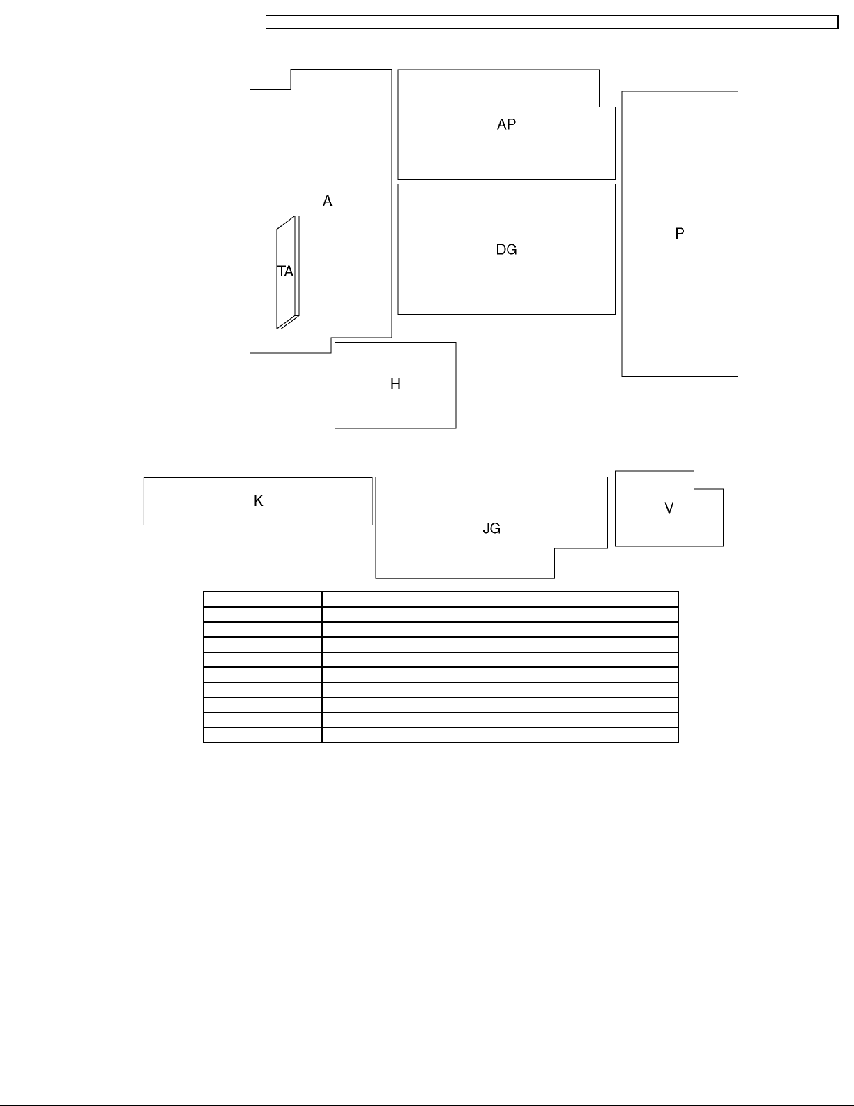
4 Chasis Board Layout
Board Name Function
A-Board AV Switch, Audio
AP-Board Regulator
DG-Board Global Core, A/D Converter, MCU
H-Board AV connector
K-Board Switch, Front Terminal
JG-Board JPEG Viewer
P-Board DC Power Supply
TA-Board Tuner
V-Board Power Switch, Remote Reciever, LED
7
TX-32LX1X / TX-32LX1M / TX-32LX1A / TX-32LX1T / TC-32LX1H / TC-32LX1DJ / TX-26LX1X / TX-26LX1M / TX-26LX1A / TX-26LX1T / TC-26LX1H
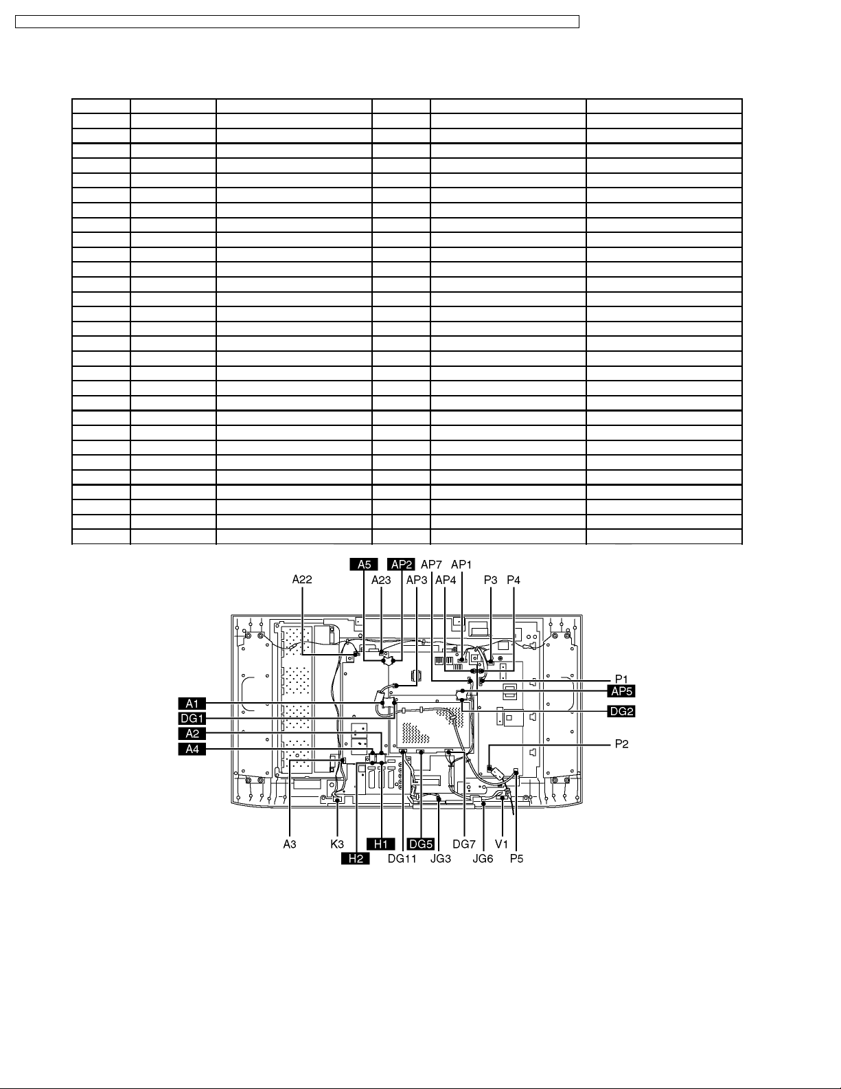
5 Before servicing
5.1. Kind and location of the flexible cable
Ref No. Flexible cable Connecter type Pins Location Opposite Ref No.
A1 l type1 50pin A-Board DG1
A2 l type1 50pin A-Board H1
A3 - - 20pin A-Board K3
A4 l type1 30pin A-Board H2
A5 l type1 20pin A-Board AP2
A22 - - 3pin A-Board speaker box R
A23 - - 3pin A-Board speaker box L
AP1 - - 6pin AP-Board P1
AP2 l type1 20pin AP-Board A5
AP3 - - 2pin AP-Board P5
AP4 - - 11pin AP-Board P4
AP5 l type1 50pin AP-Board DG2
AP7 - - 8pin AP-Board JG6
DG1 l type1 50pin DG-Board A1
DG2 l type1 50pin DG-Board AP5
DG5 l type2 30pin DG-Board LCD-panel
DG7 - - 8pin DG-Board V1
DG11 - - 11pin DG-Board JG3
H1 l type1 50pin H-Board A2
H2 l type1 30pin H-Board A4
K3 - - 20pin K-Board A3
JG3 - - 11pin JG-Board DG11
JG6 - - 8pin JG-Board AP7
P1 - - 6pin P-Board AP1
P2 - - 2pin P-Board AC-cord
P3 - - 8pin P-Board LCD-panel
P4 - - 11pin P-Board AP4
P5 - - 2pin P-Board AP3
V1 - - 8pin V-Board DG7
8
TX-32LX1X / TX-32LX1M / TX-32LX1A / TX-32LX1T / TC-32LX1H / TC-32LX1DJ / TX-26LX1X / TX-26LX1M / TX-26LX1A / TX-26LX1T / TC-26LX1H
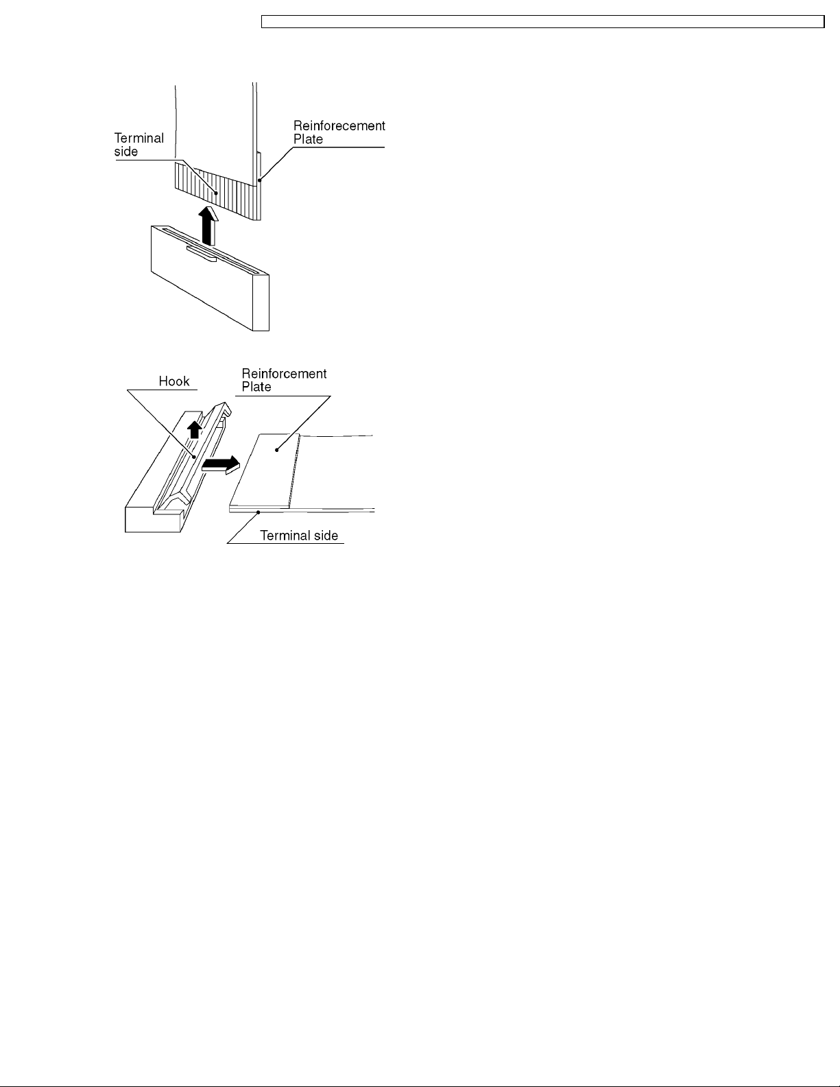
5.2. How to remove the connector
Connector type1
Connector type2
9
TX-32LX1X / TX-32LX1M / TX-32LX1A / TX-32LX1T / TC-32LX1H / TC-32LX1DJ / TX-26LX1X / TX-26LX1M / TX-26LX1A / TX-26LX1T / TC-26LX1H
6 Disassembly for Service
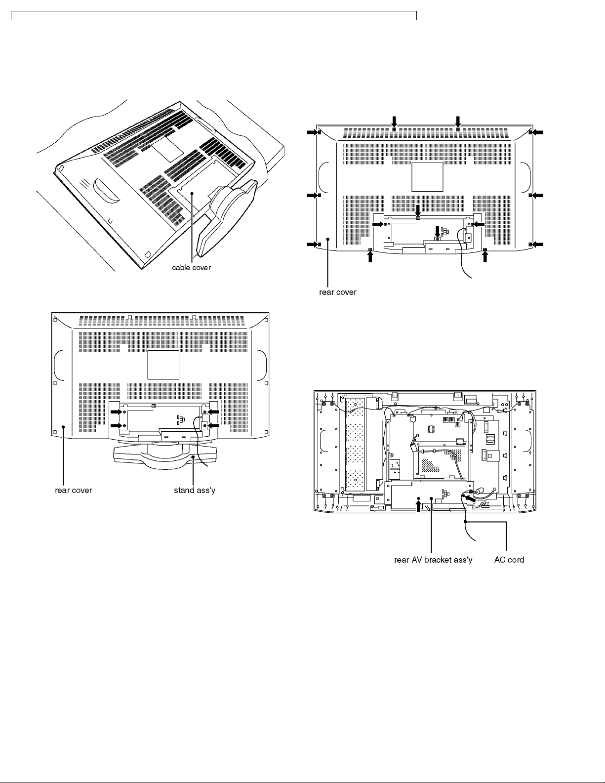
6.1. Stand ass´y
1. Lay down the main unit so that therear cover faces upward.
2. Remove the cable cover.
3. Remove the fixing screws (4pcs).
4. Remove the stand ass´y.
6.2. Rear cover
1. Remove the stand ass´y. (See 6.1.)
2. Remove the fixing screws (14pcs).
3. Remove the rear cover.
6.3. Rear AV bracket ass´y
1. Remove the rear cover. (See 6.2.)
2. Remove the AC cord.
3. Remove the fixing screws (2pcs).
4. Remove the rear AV bracket ass´y.
10
TX-32LX1X / TX-32LX1M / TX-32LX1A / TX-32LX1T / TC-32LX1H / TC-32LX1DJ / TX-26LX1X / TX-26LX1M / TX-26LX1A / TX-26LX1T / TC-26LX1H
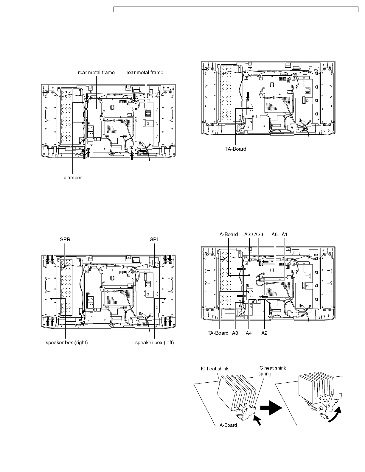
6.4. Rear metal frame
6.6. TA-Board
1. Remove the rear cover (See 6.2.) and the rear AV bracket
ass´y. (See 6.3.)
2. Unlock the cable clampers to free the cable.
3. Remove the fixing screws (6pcs).
4. Remove the rear metal frame.
6.5. Speaker box (left and right)
1. Remove the rear cover. (See 6.2.)
2. Disconnect the couplers (SPL and SPR).
3. Remove the fixing screws (8pcs).
4. Remove the speaker box (left and right).
1. Remove the rear AV bracket ass´y (See 6.3.) and the rear
metal frame. (See 6.4.)
2. Remove the fixing screw (1pcs).
3. Remove the TA-Board.
6.7. A-Board
1. Remove the rear AV bracket ass´y (See 6.3.) and the rear
metal frame. (See 6.4.)
2. Remove the TA-Board.
3. Disconnect the couplers (A3, A22 and A23) and the flexible
cables (A1, A2, A4 and A5).
4. Remove the fixing screws (4pcs).
5. Remove the A-Board.
6.8. IC heat shink
1. Pressing IC heat shink spring and pull up IC heat shink.
11
TX-32LX1X / TX-32LX1M / TX-32LX1A / TX-32LX1T / TC-32LX1H / TC-32LX1DJ / TX-26LX1X / TX-26LX1M / TX-26LX1A / TX-26LX1T / TC-26LX1H
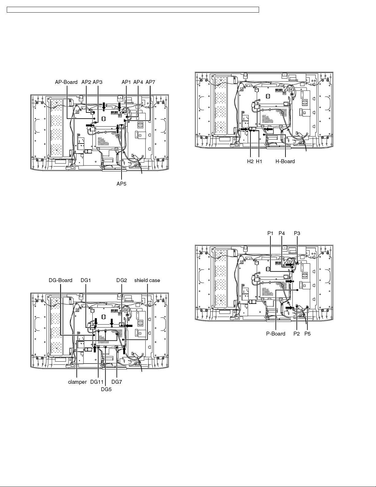
6.9. AP-Board
6.11. H-Board
1. Remove the rear AV bracket ass´y (See 6.3.) and the rear
metal frame. (See 6.4.)
2. Disconnect the couplers (AP1, AP3, AP4 and AP7) and the
flexible cables (AP2 and AP5).
3. Remove the fixing screws (4pcs).
4. Remove the AP-Board.
6.10. DG-Board
1. Remove the rear AV bracket ass´y (See 6.3.) and the rear
metal frame. (See 6.4.)
2. Unlock the cable clampers to free the cable.
3. Disconnect the couplers (DG7, and DG11) and the flexible
cables (DG1, DG2 and DG5).
4. Remove the fixing screws (5pcs).
5. Remove the shield case.
6. Remove the DG-Board.
1. Remove the rear AV bracket ass´y (See 6.3.) and the rear
metal frame. (See 6.4.)
2. Disconnect the flexible cables (H1 and H2).
3. Remove the fixing screws (2pcs).
4. Remove the H-Board.
6.12. P-Board
1. Remove the rear AV bracket ass´y (See 6.3.) and the rear
metal frame. (See 6.4.)
2. Disconnect the couplers (P1, P2, P3, P4 and P5).
3. Remove the fixing screws (3pcs).
4. Remove the P-Board.
12
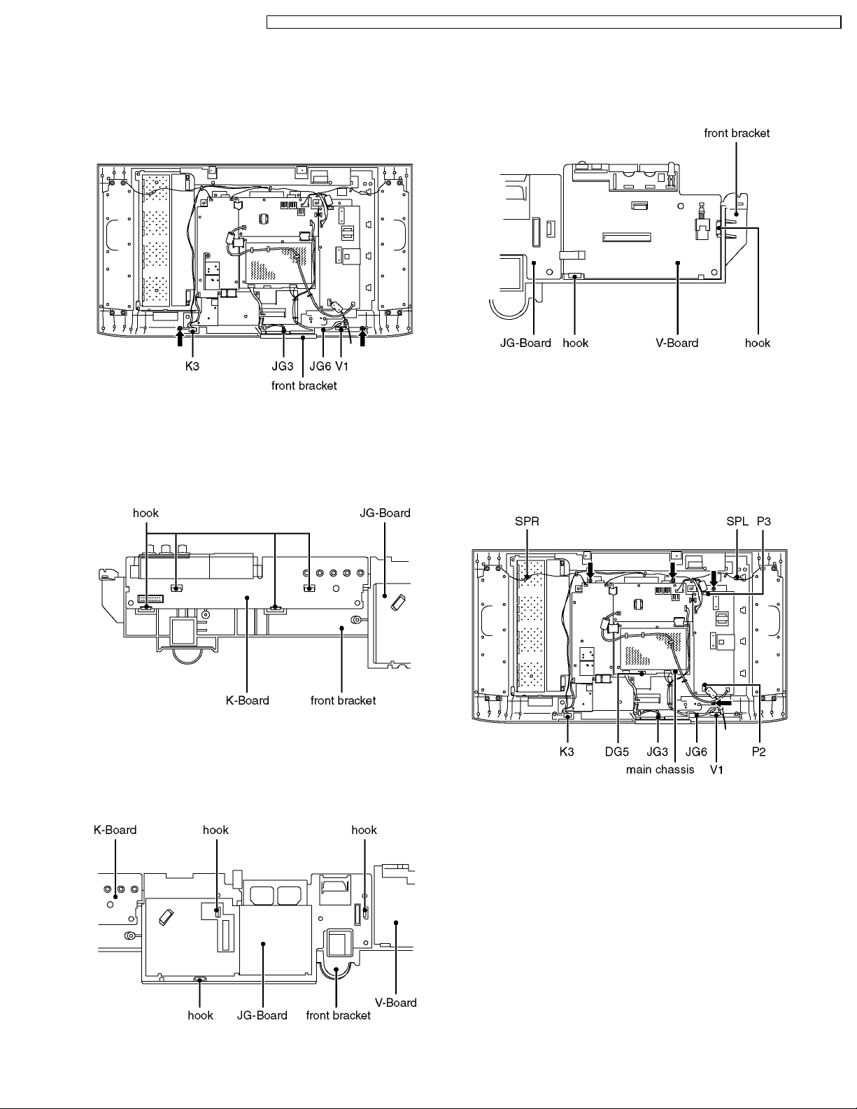
6.13. Front bracket
TX-32LX1X / TX-32LX1M / TX-32LX1A / TX-32LX1T / TC-32LX1H / TC-32LX1DJ / TX-26LX1X / TX-26LX1M / TX-26LX1A / TX-26LX1T / TC-26LX1H
6.16. V-Board
1. Remove the rear AV bracket ass´y (See 6.3.) and the rear
metal frame. (See 6.4.)
2. Disconnect the couplers (K3, JG3, JG6 and V1).
3. Remove the fixing screws (2pcs).
4. Remove the front bracket.
6.14. K-Board
1. Remove the front bracket. (See 6.13.)
2. Remove the hooks (4place).
3. Remove the K-Board.
1. Remove the front bracket. (See 6.13.)
2. Remove the hooks (2place).
3. Remove the V-Board.
6.17. Main chassis
1. Remove the rear AV bracket ass´y (See 6.3.) and the rear
metal frame. (See 6.4.)
2. Disconnect the couplers (K3, JG3, JG6, V1, P2, P3, SPL
and SPR) and the flexible cables (DG5).
3. Remove the fixing screws (4pcs).
4. Remove the main chassis.
6.15. JG-Board
1. Remove the front bracket. (See 6.13.)
2. Remove the hooks (3place).
3. Remove the JG-Board.
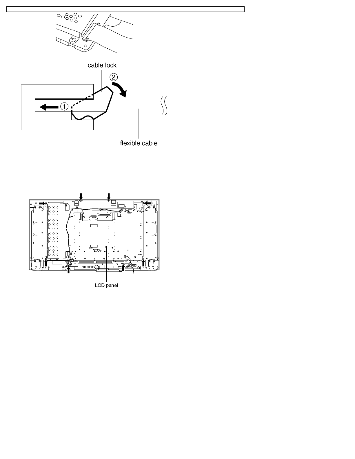
·
· Disconnecting flexible cable from the coupler.
· ·
Lift up both ends of the cable lock (brown colored)
simultaneously to release the locking. Once the flat cable is
disconnected from the coupler, the cable lock tends to
detach from the coupler easily. Due precaution should be
paid on it.
·
· Reconnecting flexible cable to the coupler.
· ·
Attach the cable lock (brown) to the coupler (white) with its
both ends being pulled up. Insert the flat cable into the
coupler over the cable lock until the cable stops firmly at the
coupler end. Press down both ends of the cable lock until
their upper faces are positioned flat to lock the cable.
13
TX-32LX1X / TX-32LX1M / TX-32LX1A / TX-32LX1T / TC-32LX1H / TC-32LX1DJ / TX-26LX1X / TX-26LX1M / TX-26LX1A / TX-26LX1T / TC-26LX1H
6.18. LCD panel
1. Remove the main chassis. (See 6.17.)
2. Remove the fixing screws (8pcs).
3. Remove the LCD panel.
14
TX-32LX1X / TX-32LX1M / TX-32LX1A / TX-32LX1T / TC-32LX1H / TC-32LX1DJ / TX-26LX1X / TX-26LX1M / TX-26LX1A / TX-26LX1T / TC-26LX1H
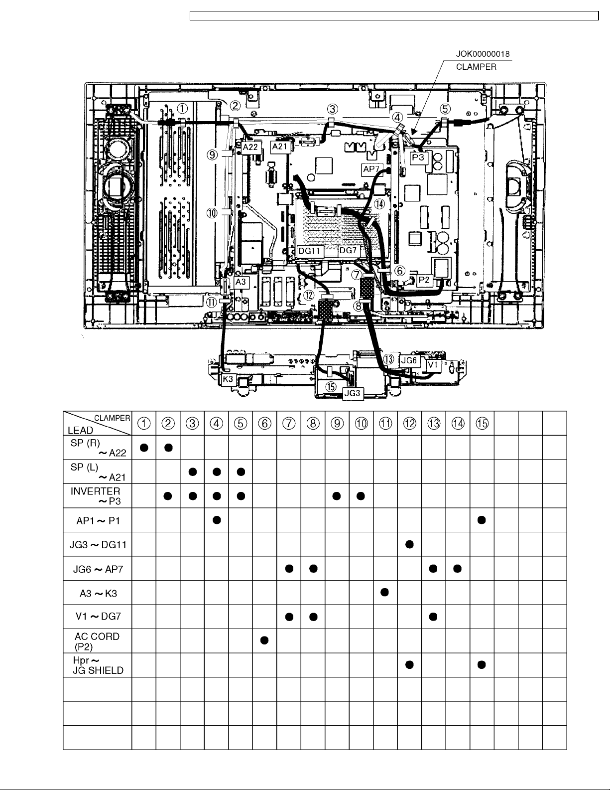
7 Location of Lead Wiring
15

TX-32LX1X / TX-32LX1M / TX-32LX1A / TX-32LX1T / TC-32LX1H / TC-32LX1DJ / TX-26LX1X / TX-26LX1M / TX-26LX1A / TX-26LX1T / TC-26LX1H
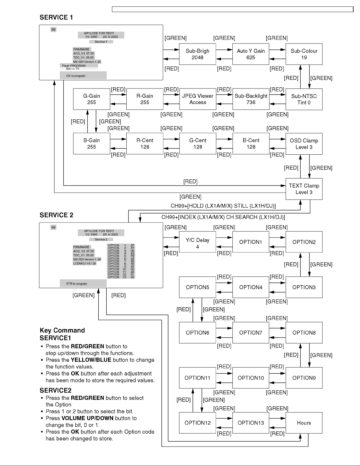
8 Service Mode Function
MPU controls the functions switching for each IICs through IIC bus in this chassis. The following setting and adjustment can be
adjusted by remote controller in Service Mode.
8.1. How to enter SERVICE 1
1. In main menu, choose sound menu, set BASS to MAXIMUM, and set TREBLE to MINIMUM.
2. Simultaneously press INDEX (LX1A/M/X) CH SEARCH (LX1H/DJ) button on remote controller and DOWN button [
TV set.
8.2. How to enter SERVICE 2
1. Enter SERVICE 1
2. Select the “TEXT Clamper Level”.
3. Set the channel to CH99.
4. Press HOLD (LX1A/M/X) STILL (LX1H/DJ) button on remote controller.
Note:
To exit to Service mode, press Power button on remote controller.
] on the
16
TX-32LX1X / TX-32LX1M / TX-32LX1A / TX-32LX1T / TC-32LX1H / TC-32LX1DJ / TX-26LX1X / TX-26LX1M / TX-26LX1A / TX-26LX1T / TC-26LX1H
17
TX-32LX1X / TX-32LX1M / TX-32LX1A / TX-32LX1T / TC-32LX1H / TC-32LX1DJ / TX-26LX1X / TX-26LX1M / TX-26LX1A / TX-26LX1T / TC-26LX1H
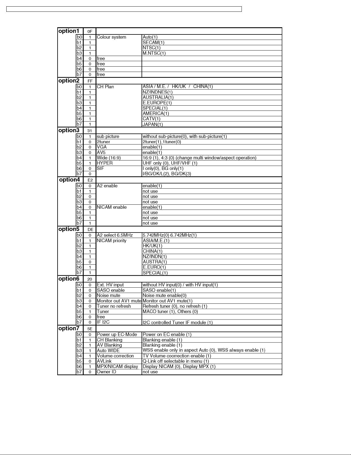
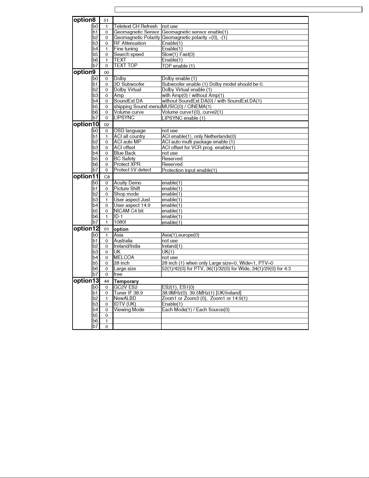
8.3. Option Description
18
TX-32LX1X / TX-32LX1M / TX-32LX1A / TX-32LX1T / TC-32LX1H / TC-32LX1DJ / TX-26LX1X / TX-26LX1M / TX-26LX1A / TX-26LX1T / TC-26LX1H
19
TX-32LX1X / TX-32LX1M / TX-32LX1A / TX-32LX1T / TC-32LX1H / TC-32LX1DJ / TX-26LX1X / TX-26LX1M / TX-26LX1A / TX-26LX1T / TC-26LX1H
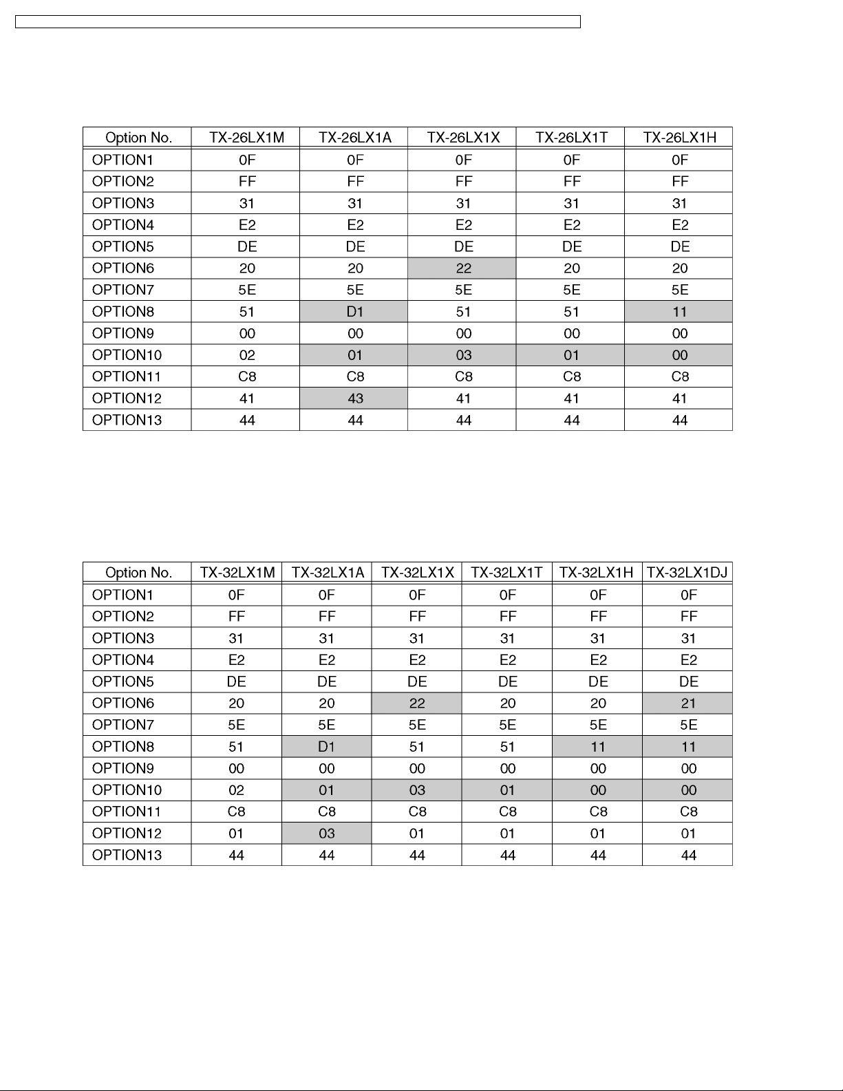
8.4. Option Code Setting (26 inch model)
If the memory IC (IC1115) or DG Board is replaced, option code should be re-memorized.
Spare part of IC1115 is already memorized all Data for TX-26LX1M.
If you use for other model, you should re-memorized the different option code in SERVICE 2 mode.
8.5. Option Code Setting (32 inch model)
If the memory IC (IC1115) or DG Board is replaced, option code should be re-memorized.
Spare part of IC1115 is already memorized all Data for TX-32LX1M.
If you use for other model, you should re-memorized the different option code in SERVICE 2 mode.
20
TX-32LX1X / TX-32LX1M / TX-32LX1A / TX-32LX1T / TC-32LX1H / TC-32LX1DJ / TX-26LX1X / TX-26LX1M / TX-26LX1A / TX-26LX1T / TC-26LX1H
9 Adjustment method
9.1. Video Signal Level Adjustment
9.1.1. RF video
Instrument Name Connect to Remarks
Remote controller
Internal signal (100% composite picture color bar)
1. Receive composite picture color bar (100% PAL) by RF signal input.
(Aspect mode : wide, Viewing mode: standard, LCD AI: OFF)
2. Go to "Auto Y Gain" under Service 1 and make automatic adjustment of video signal level by the blue key.
·
· When Service 1 appears, presetting takes place automatically as shown below.
· ·
·
· Sharpness: 0
· ·
·
· AI: OFF
· ·
·
· Comb filter : On
· ·
3. Press STR key to write the value of adjustment results to EEPROM.
4. Check that the automatic adjustment of video signal level has completed normally.
·
· When the adjustment is completed normally, the "Auto Y Gain" color turns black.
· ·
9.1.2. RF AGC adjustment (Auto adjustment)
RF input
1. Receive RF signal, and enter the Service 1, RF AGC adjustment mode.
2. The adjustment will be finished automatically if blue key ispressed on the remote controller. (The character colour will be black
if finished.)
3. Change the input signal strength and check the RF AGC Reference value is as follows.
·
· Signal strength: 63dB = about 130 to 140
· ·
·
· Signal strength: 93dB = about 60 to 70
· ·
·
· Signal strength: 33dB = about 190 to 200
· ·
9.2. WB Adjustment
Instrument Name Connect to Remarks
1. Remote controller
2. LCD WB meter (Minolta CS-1000 equivalent)
3. Communication jig
4. Computer for external control
·
· Basically perform checking using the production software and make automatic adjustment using external computer.
· ·
·
· Let the panel stand for more than 3 hours at 20 °C to 25 °C.
· ·
·
· Basically perform assemble to completion in the ambient environment of room temperature 20 °C to 25 °C.
· ·
1. Enter into WB adjustment in the plant adjustment mode and measure the WHITE brightness data to check that it is higher than
400 cd /m
(When it is below 400 cd /m
2. For the Excel calculation sheet, use "LX1 series, calculation software".
3. Using the jig, measure the brightness and chromaticity coordinates of single colors, white, red, green and blue, at the maximum
brightness (using basic data) and calculate the gamma data corrected at the maximum brightness using Excel calculation sheet
on the external computer.
4. Write the values calculated in 3 above in the gamma data part in EEPROM.
EEPROM Adr: 0C58h ~ 0C5Bh, 0C5Ch ~ C5Fh ...R (color temperature Normal)
Note:
5. Reflect the data in 4 above and select gray and measure the brightness and chromaticity coordinate at that time and calculate
the gamma data (color temperature, normal) and cool and warm color temperatures, corrected at half-tone, using the external
computer.
2
.
2
, make re-measurement in 30 minutes after cold-on.)
0C08h ~ 0C0Bh, 0C0Ch ~ 0C0Fh ...G (color temperature Normal)
0C30h ~ 0C33h, 0C34h ~ 0C37h ...B (color temperature Normal)
For T.T., P.P. and M.P., record the brightness and chromaticity coordinates for white, red, green and blue.
Adjustment terminal Correlation can be also taken
by CA-110 or equivalent
21

TX-32LX1X / TX-32LX1M / TX-32LX1A / TX-32LX1T / TC-32LX1H / TC-32LX1DJ / TX-26LX1X / TX-26LX1M / TX-26LX1A / TX-26LX1T / TC-26LX1H
6. Write the values calculated in 5 above in the gamma data part in EEPROM.
EEPROM Adr: 0C58h ~ 0C5Bh, 0C5Ch ~ 0C5Fh ...R (color temperature Normal)
0C08h ~ 0C0Bh, 0C0Ch ~ 0C0Fh ...G (color temperature Normal)
0C30h ~ 0C33h, 0C34h ~ 0C37h ...B (color temperature Normal)
0C50h ~ 0C53h, 0C54h ~ 0C57h ...R (color temperature Warm)
0C00h ~ 0C03h, 0C04h ~ 0C07h ...G (color temperature Warm)
0C28h ~ 0C2Bh, 0C2Ch ~ 0C2Fh ...B (color temperature Warm)
0C60h ~ 0C63h, 0C64h ~ 0C67h ...R (color temperature Cool)
0C10h ~ 0C13h, 0C14h ~ 0C17h ...G (color temperature Cool)
0C38h ~ 0C3Bh, 0C3Ch ~ 0C3Fh ...B (color temperature Cool)
Note:
For T.T., P.P. and M.P., record the brightness and chromaticity coordinates for white, red, green, and blue at CHECK and
GRAY in the final gamma setting.Also for P.P. and M.P. record the brightness and chromaticity coordinates at color
temperatures Normal and Warm.
7. Reflect the data in 6 above and CHECK that the chromaticity coordinates, at check and GRAY, are within the values given
below.
CHECK: x= 0.2839 y= 0.2884 (TX-32LX1M, TC-32LX1D Series), x=0.2900, y=0.2930 (TX-26LX1M, TC-26LX1D Series)
GRAY: x= 0.29 y= 0.29 (TX-32LX1M, TC-32LX1D Series), x=0.2914, y=0.2914 (TX-26LX1M, TC-26LX1D Series)
·
· When writing data into EEPROM, make this procedure after sending the WP (write protect) cancellation command (70 88
· ·
00). Also, WP (write protect) setting command is 70 88 FF.
8. EEPROM DATA saving place for WB (gamma data) backup
<Housing address> <Writing address>
<32 inch>
0C18h ~ 0C1Bh ® 0C08h ~ 0C0Bh
0C1Ch ~ 0C1Fh ® 0C0Ch ~ 0C0Fh
0C40h ~ 0C43h ® 0C30h ~ 0C33h
0C44h ~ 0C47h ® 0C34h ~ 0C37h
0C68h ~ 0C6Bh ® 0C58h ~ 0C5Bh
0C6Ch ~ 0C6Fh ® 0C5Ch ~ 0C5Fh
<26 inch>
0C20h ~ 0C23h ® 0C08h ~ 0C0Bh
0C24h ~ 0C27h ® 0C0Ch ~ 0C0Fh
0C48h ~ 0C48h ® 0C30h ~ 0C33h
0C4ch ~ 0C4Fh ® 0C34h ~ 0C37h
0C70h ~ 0C73h ® 0C58h ~ 0C5Bh
0C74h ~ 0C77h ® 0C5Ch ~ 0C5Fh
Note:
After completion of adjustment, record the completion time if it took more than 35 minutes after aging.
22
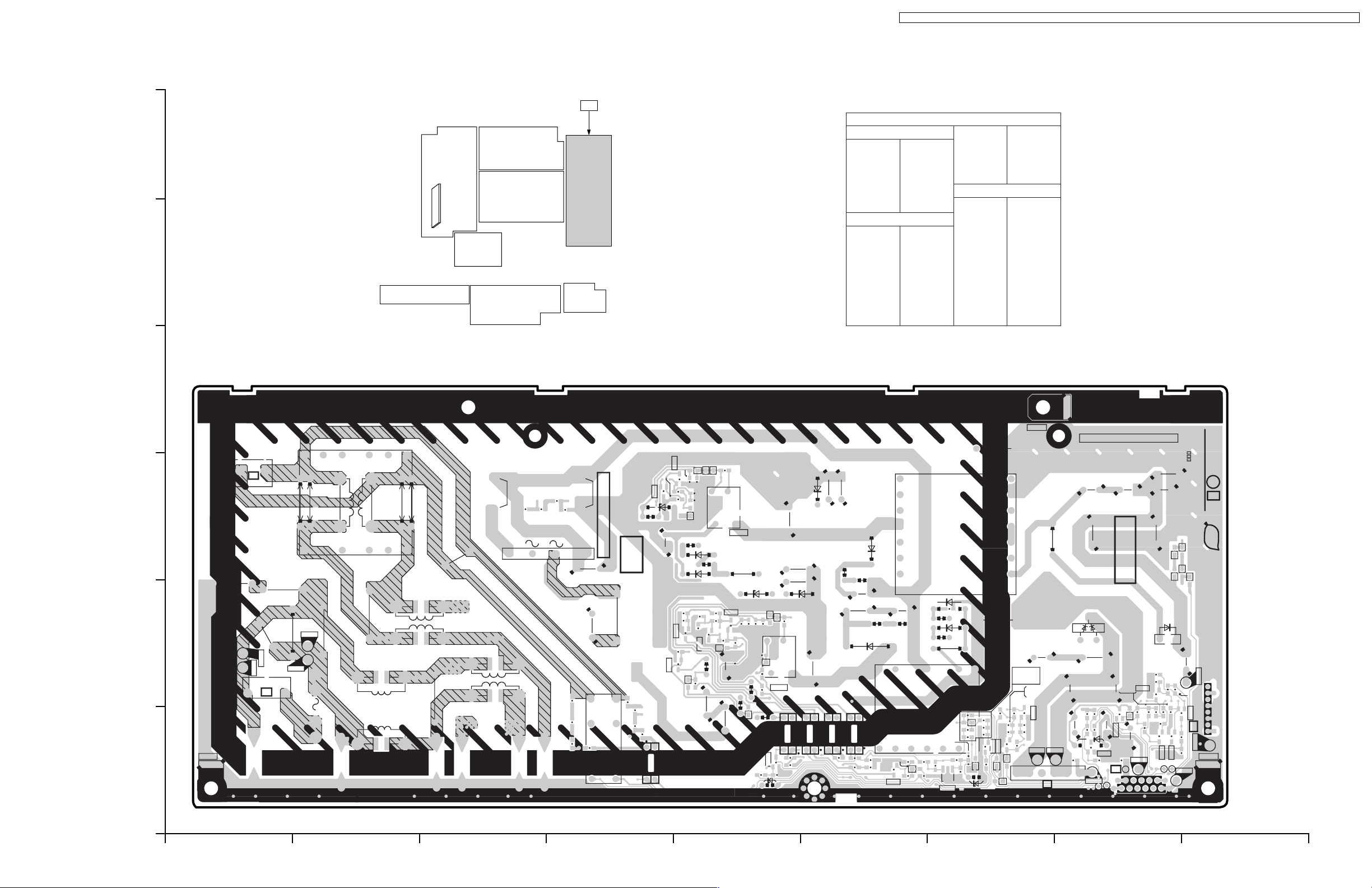
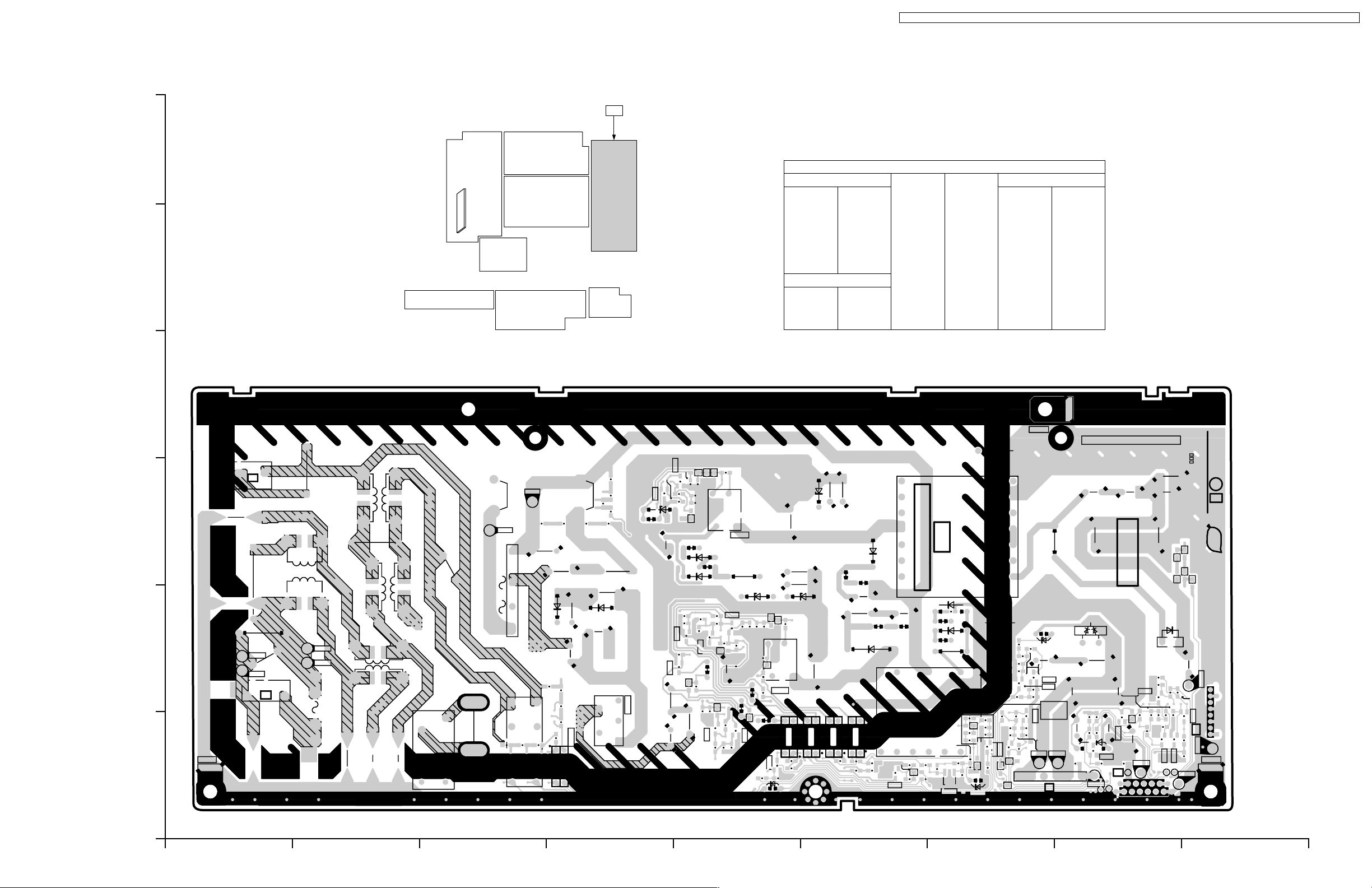
10 Conductor Views
10.1. P-Board
TX-32LX1X / TX-32LX1M / TX-32LX1A / TX-32LX1T / TC-32LX1H / TC-32LX1DJ / TX-26LX1X / TX-26LX1M / TX-26LX1A / TX-26LX1T / TC-26LX1H
P
Parts Location
P-BOARD (FOIL SIDE)
IC
6
IC7100 E-3
IC7101 E-2
IC7102 F-1
IC7103 F-1
IC7104 F-1
IC7105 E-1
IC7106 G-1
IC7108 D-1
TRANSISTOR
Q7100 E-2
Q7101 D-3
Q7102 E-3
5
Q7103 E-2
Q7104 E-2
Q7105 F-1
Q7106 E-1
Q7107 G-1
Q7109 H-1
Q7113 E-2
Q7114 H-1
Q7115 H-1
Q7116 H-1
Q7117 H-2
Q7118 I-1
Q7119 G-1
Q7120 G-1
TP
TP000 B-2
TP001 A-2
TP002 B-2
TP003 A-2
TP101 G-1
TP102 G-1
TP103 H-1
TP104 I-1
TP105 I-2
TP106 H-1
TP107 H-1
P-BOARD (FOIL SIDE)
TNPA3071AE (TC-32LX1DJ, TX-32LX1T)
TNPA3071AF (TX-26LX1T)
4
ZA004
LF002
3
JSD2
JSD1
4
LF001
C001
D001
C103
D100
-
LF000
R103
R102
R101
R100
R003
R001
R002
C100
+
C125
R010
RL100
R004
LIVE CIRCUIT
D116
R112
HOT
C010
R005
R006
R007
R008
IC108
Q101
R117
R116
C113
R191
C045
Q113
2
13
P5
JSD3
3
JSD4
LF003
1
FL001
C047
C046
C006
R000
D000
2
ZA001
1
TP003
TP001
P2
TP002
C000
TP000
2
F000
1
C003 C005
C002C004
Q102
Q100
C109
R113
D111
C106
D106
D107
R119
C111
R118
C110
R136
Q103
R127
R122
D109
D103
R115
6
D110
R114
R120
D131
5
R190
C114
R126
R108
D108
R121
Q104
R104
R106
D101
C101
37
IC100
R189
R188
L107
R123
1
C107
D126
R111
R124
C112
R154
D122
R110
D138
C108
R187
R135
Q106
D105
D104
5
IC101
R137
R152
R109
D115
37
IC105
D113
R132
R107
R105
D102
C102
R130
D114
R134
R131
C115
P2PTP1F2F1
C116
JS101
R133
1
16
IC102
IC103
IC104
14
R139
R146
R144
R141
R138
R143
R145
Q105
D130
R153
D137
R186
R192
R149R151
R147
D112
T001
C129
IC106
T003
R160
R159
C136
R161
7
D132
9
R140
D117
D123
Q107
R207
Q120
D124
D141
R163
D129
R167
R142
R204
6
C119
S2
STA
STB
S1
C117
R205
C122
R162
R164
C123
R206
C131
Q119
C130
R203
TP101 TP102
R158
R195
R196
D121
R169
TP103
R200
R198
Q117
R194
R193
C126
R197
C135
D142D143
D118
Q109
Q116
10
11
C120C121
C124
L105
D125
C128
R177
C134
R180
D120
C118
1
P1
TP106
R148
R178
C127
C133
R179
Q114
R181
COLD
R201
Q115
C141
R165
P4
2
1
TNPA3071
CRNO.7
SEE REVERSE FOR ORDER NO.
1P
PbF
D144
D146
D145
L104
TP105
18
R199
R170
Q118
P3
R202
TP104
R168
ZA002
TP107
TC-32LX1DJ, TX-32LX1T
P-BOARD TNPA3071AE
A
TX-26LX1T
P-BOARD TNPA3071AF
TX-26LX1T
P-BOARD TNPA3071AF
TC-32LX1DJ, TX-32LX1T
P-BOARD TNPA3071AE
C E GIBDFH
23

TX-32LX1X / TX-32LX1M / TX-32LX1A / TX-32LX1T / TC-32LX1H / TC-32LX1DJ / TX-26LX1X / TX-26LX1M / TX-26LX1A / TX-26LX1T / TC-26LX1H
P
6
IC
IC7102 D-1
IC7103 D-1
IC7104 D-1
IC7105 D-1
IC7101 D-2
IC7108 E-1
IC7100 E-3
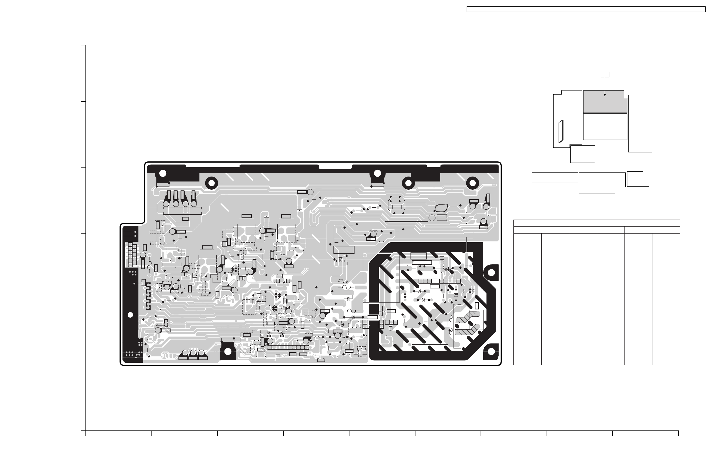
P-BOARD (COMPONENT SIDE)
5
P-BOARD (COMPONENT SIDE)
TNPA3071AE (TC-32LX1DJ, TX-32LX1T)
TNPA3071AF (TX-26LX1T)
4
ZA004
Parts Location
C119
R158
C135
C126
C120 C121
C124
S2STASTBS1
3
COLD
2
ZA002
1
D118
L104
18
P3
11
R148
C127
C141
P4
D125
C133
16
210
1
L105
C117
C122
C128
C134
D120
P1
T003
D113
PT P1 F2 F1
R131
D137
R186
R192
T001
C116
R133 R134
P2
R130
D114
1
IC102
D112
JS101
7
914
D117
C115
R106
R132
IC103
D102
R104
C102
D101
IC104
IC105
D115
37
5
16
C101
R107
R105
3
7
5
16
IC101
IC100
D108
R121
L107
D122
R111
R188
R137
R126
R115
D110
R190
C114
R127
IC108
D116
R112
C113
HOT
LIVE CIRCUIT
C010
RL100
C125
R010
C100
+
D100
LF000
C103
-
C003C005
3
4
D001
LF001
C001
C002 C004
JSD1
JSD2
LF003
C006
LF002
F000
2
13
FL001
JSD3
JSD4
1
C046
C000
R000
P2
21
T5AH
C047
D000
P5
CRNO.7
1P
TNPA3071
NO.
ORDER
ZA001
TC-32LX1DJ, TX-32LX1T
P-BOARD TNPA3071AE
A
TX-26LX1T
P-BOARD TNPA3071AF
TX-26LX1T
P-BOARD TNPA3071AF
TC-32LX1DJ, TX-32LX1T
P-BOARD TNPA3071AE
C E GIBDFH
24
TX-32LX1X / TX-32LX1M / TX-32LX1A / TX-32LX1T / TC-32LX1H / TC-32LX1DJ / TX-26LX1X / TX-26LX1M / TX-26LX1A / TX-26LX1T / TC-26LX1H
P
6
Parts Location
P-BOARD (FOIL SIDE)
IC
IC7100 E-3
IC7101 E-2
IC7102 F-1
IC7103 F-1
IC7104 F-1
IC7105 E-1
IC7106 G-1
5
IC7107 D-1
IC7108 D-1
TRANSISTOR
Q7100 E-2
Q7101 D-3
Q7102 E-3
Q7103 E-2
Q7104 E-2
Q7105 F-1
Q7106 E-1
Q7107 G-1
Q7109 H-1
Q7113 D-2
Q7114 H-1
Q7115 H-1
Q7116 H-1
Q7117 H-2
Q7118 I-1
Q7119 G-1
Q7120 G-1
Q7121 G-2
Q7122 G-2
Q7200 E-1
Q7201 E-1
TP
TP7000 B-2
TP7001 A-2
TP7002 B-2
TP7003 A-2
TP7004 C-3
TP7005 C-3
TP7101 G-1
TP7102 H-1
TP7103 H-1
TP7104 I-1
TP7105 I-2
TP7106 H-1
TP7107 H-1
P-BOARD (FOIL SIDE)
TNPA3285AA (TC-32LX1H, TX-32LX1A/M/X)
TNPA3285AD (TC-26LX1H, TX-26LX1A/M/X)
4
ZA004
ZA004
C004
C004
3
3
1
1
P5
P5
3
2
ZA001
ZA001
C002
C002
R000
R000
TP003
TP003
TP001
TP001
C000
C000
1
1
LF002
LF002
TP002
TP002
TP000
D000
D000
P2
P2
TP000
2
2
C001
C001
F000
F000
C003
C003
C006
C006
LF000
LF000
LF003
LF003
C005
C005
LF001
LF001
RL101
RL101
D001
D001
R010
R010
C100
C100
R001
R001
TP004
TP004
+
+
-
-
TP005
TP005
D100
D100
RL100
RL100
R002R003
R002R003
R103
R103
C125
C125
R005
R005
R004
R004
R102
R102
R125
R125
D139
D139
R006
R006
R007 R008
R007 R008
C103
C103
IC108
IC108
C104
C104
C138
C138
R101
R101
R211 R212
R211 R212
R213
R213
R214
R214
R100
R100
C140
C140
C105
C105
D140
D140
C137
C137
24
24
R117
R117
R116
R116
Q101
Q101
D116
D116
R112
R112
C113
C113
C045
C045
R191
R191
Q113
Q113
R127
C139
C139
R127
IC107
IC107
1
1
5
5
1
Q102
Q102
Q100
Q100
R113
R113
C109
C109
R126
R126
D111
D111
C106
C106
D106
D106
D107
D107
R119
R119
C111
C111
R118
R118
C110
C110
R215
R215
Q103
Q103
R136
R136
R217
R217
D103
D103
R115
R115
R122
R122
D109
D109
Q201
Q201
R218
R218
6
6
D110
D110
C200
C201
C201
C200
D131
D131
R114
R114
R120
R120
R190
R190
R104
R106
R104
R106
D101
D101
R108
R108
LIVE CIRCUIT
C101
C101
37
37
5
5
1
1
IC100
D200
D200
D108
D108
R121
R121
C114
C114
Q104
Q104
R216
R216
IC100
R189
R189
R188
R188
L107
L107
R123
R123
C107
C107
D126
D126
R111
R111
Q200
Q200
R124
R124
C112
C112
R154
R154
D122
D122
R110
R110
D138
D138
C108
C108
R187
R187
R135
R135
Q106
Q106
D105
D105
5
5
IC101
IC101
R137
R137
D104
D104
R152
R152
R109
R109
IC105
IC105
D115
D115
R107
R107
R105
R105
D102
D102
37
37
C102
C102
16
16
IC104
IC104
R139
R139
R146
R146
IC103
IC103
R144
R144
R132
R132
R141
R141
R138
R138
R130
R130
IC102
IC102
D113
D113
D114
D114
R134
R134
R143
R143
R145
R145
R131
R131
C115
C115
1
1
14
14
LIVE CIRCUIT
P2PTP1F2F1
P2PTP1F2F1
D112
D112
C116
C116
JS101
JS101
D137
D137
R133
R133
R186
R186
R192
R192
T001
T001
R149R151
R149R151
D130
D130
R153
R153
Q105
Q105
R147
R147
HOT
HOT
C129
C129
IC106
IC106
R160
R160
R159
R159
T003
T003
C136
C136
R161
R161
7
7
D132
D132
9
9
R140
R140
D117
D117
Q107
Q107
D123
D123
Q120
Q120
R207
R207
D141
D141
R204
R204
6
6
D124
D124
S2
S2
STA
STA
STB
STB
S1
S1
R157
R157
C119
C119
C117
C117
R205
R205
D148
D148
R210
R210
C122
C122
R156
R156
R155
R155
C143
C143
C142
C142
R208R209
R208R209
D129
D129
Q119
Q119
R167
R167
R142
R142
C130
C130
R203
R203
R206
R206
C131
C131
TP101 TP102
TP101 TP102
Q122
Q122
Q121
Q121
R158
R158
C135
R196
R196
D121
D121
R169
R169
TP103
TP103
R200
R200
R198
R198
Q117
Q117
R194
R194
R193
R193
C126
C126
R197
R197
C135
D142D143
D142D143
D118
D118
Q116
Q116
Q109
Q109
10
10
11
11
C120C121
C120C121
C124
C124
L105
L105
D125
D125
C128
C128
R177
R177
R162R163
R162R163
R164
R164
C123
C123
C134
C134
R180
R180
D120
D120
C118
C118
1
1
P1
P1
R148
R148
TP106
TP106
R178
R178
R181
R181
R179
R179
Q114
Q114
COLD
COLD
R201
R201
R195
R195
C127
C127
C133
C133
Q115
Q115
C141
C141
R165
R165
P4
P4
2
2
1
1
TP107
TP107
D145
D145
CRNO.7
CRNO.7
D144
D144
L104
L104
R199
R199
Q118
Q118
P3
P3
R202
R202
R168
R168
R170
R170
TP104
TP104
D146
D146
SEE REVERSE FOR ORDERNO.
SEE REVERSE FOR ORDERNO.
TP105
TP105
TNPA3285
TNPA3285
1P
1P
PbF
PbF
1
1
8
8
ZA002
ZA002
TC-32LX1H, TX-32LX1A/M/X
P-BOARD TNPA3285AA
A
TC-26LX1H, TX-26LX1A/M/X
P-BOARD TNPA3285AD
TC-32LX1H, TX-32LX1A/M/X
P-BOARD TNPA3285AA
TC-26LX1H, TX-26LX1A/M/X
P-BOARD TNPA3285AD
C E GIBDFH
25

TX-32LX1X / TX-32LX1M / TX-32LX1A / TX-32LX1T / TC-32LX1H / TC-32LX1DJ / TX-26LX1X / TX-26LX1M / TX-26LX1A / TX-26LX1T / TC-26LX1H
P
6
IC
IC7100 E-3
IC7101 D-2
IC7102 D-1
IC7103 D-1
IC7104 D-1
IC7105 D-1
IC7107 E-1
IC7108 F-1
P-BOARD (COMPONENT SIDE)
5
P-BOARD (COMPONENT SIDE)
TNPA3285AA (TC-32LX1H, TX-32LX1A/M/X)
TNPA3285AD (TC-26LX1H, TX-26LX1A/M/X)
4
ZA004
Parts Location
C119
R158
C135
C126
C120 C121
C124
S2STASTBS1
3
COLD
L105
C117
2
ZA002
1
D118
L104
1
P3
8
10
11
R148
C127
C141
P4
D125
C133
2
1
D148
C122
C128
C134
D120
P1
1
6
T003
PT P1 F2 F1
R131
D137
R186
R192
T001
C116
R133 R134
P2
D114
D112
JS101
7
914
D117
1
D113
IC102
R130
C115
R106
IC103
R132
D102
R104
C102
IC104
D101
C101
R107
R105
3
5
16
IC101
IC105
D115
37
5
16
IC100
D108
R121
L107
D122
7
R111
R188
R137
R115
D110
R190
C114
R126
D116
R112
C140
C113
C105
D140
C137
HOT
R127
1
LIVE CIRCUIT
IC107
5
C139
C103
C125
R125
C104
D139
C138
24
IC108
-
RL100
C100
+
D100
R010
D001
RL101
LF001
LF003
C006
C005
C003
C001
LF000
F000
13
C004
P5
LF002
R000
D000
P2
21
T5AH
C002
C000
CRNO.7
1P
NO.
TNPA3285
ORDER
ZA001
TC-32LX1H, TX-32LX1A/M/X
P-BOARD TNPA3285AA
A
TC-26LX1H, TX-26LX1A/M/X
P-BOARD TNPA3285AD
TC-32LX1H, TX-32LX1A/M/X
P-BOARD TNPA3285AA
TC-26LX1H, TX-26LX1A/M/X
P-BOARD TNPA3285AD
C E GIBDFH
26
10.2. AP-Board
TX-32LX1X / TX-32LX1M / TX-32LX1A / TX-32LX1T / TC-32LX1H / TC-32LX1DJ / TX-26LX1X / TX-26LX1M / TX-26LX1A / TX-26LX1T / TC-26LX1H
6
5
4
3
2
AP-BOARD (FOIL SIDE)
TNPA3072AC (TC-32LX1F, TX-32LX1A/M/X)
TNPA3072AF (TC-26LX1F, TX-26LX1A/M/X)
ZA802
TP803
TP804
1
Q810
R859
R858
C839
10
11
1
C841
AP4
TP805
R959
2
AP7
R947
C882
R946
R945
R948
R949
C883
R837
L802
D854
Q823
C834
R885
R889
TP814
R942
8
TP811
L821
R950
R944
C849
L820
Q842
TP826
1
TP802
AP1
TP806
C823
R844
C833
C829
D830
D829
C838
C830
TP818 TP819TP820
R848
TP809
Q811
C843
C840
TP801
R849
6
C842
C844
R861
Q812
D856
IC806
5
4
C837
L803
R847
3
2
1
R860
R846
Q835
R840
R921
TP807
ZA801
TP824
R918
C825
D848
C875
C821
L805
R919
TNPA3072AG (TC-32LX1DJ, TX-32LX1T)
TNPA3072AH (TX-26LX1T)
R825
2
S4B
S4A
S3B
S3A
S2
S1
R824
C864
R832
ZA803
R933
C879
TNPA3072
SEE REVERSE FOR ORDERNO.
L801
T801
IC802
R952
D812
R951
R821
Q802
SGD
R803
C801
TP829
3
V2 V1 P1 PT P2
C817
D801
R934
HOT
LIVE CIRCUIT
R823
R818
D809
C805
PbF
AP
4
D808
D805
C804
R820
13 6
IC801
D804
R817
C803
C810
R808
D813
-
+
R816
10
C871
R822
D806
D803
L809
C806
L812
C808
C802
TP822
L814
1
D802
AP3
TP821
TP823
L813
L811
Parts Location
AP-BOARD (FOIL SIDE)
IC
IC801 F-3
IC802 E-2
IC806 B-3
IC807 C-3
IC808 D-3
IC809 E-2
3
TRANSISTOR
Q802 E-2
Q810 B-4
Q811 B-3
Q812 C-3
Q821 D-3
Q823 A-3
Q826 D-2
Q827 C-2
Q828 C-3
Q829 C-2
Q831 D-2
Q835 C-3
Q837 D-2
Q838 C-2
Q842 A-2
Q845 D-2
4
TP812
D857
Q831
C847
C845
C881
Q845
C819
TP828
R954
C811
COLD
C816
C815
C818
TP827
C853
C846
R890
R878
R881
R883
L807
Q821
R880
R893
R922
C876
R923
Q837
C885
R953
TP825
L817
1
Q826
D814
R829
C855
R963
C851
R916
L830
D815
IC809
C861
C813
C809
D816
R915
R827
R831
C814
C878
1
D855
IC807
3
5
2
1
4
C822
R911
R842
R850
C835
TP810
C832
C836
C870
D825
D823
C857
R900
R908
R905
D843
L806
R896
R897
Q827
R929
TP813
Q838
R927 R928
L804
C869
R903
D835
TP808
Q829
C826
10
C866
Q828
D838
L808
D839
C859
D846
R873
D850
R943
IC808
3
5
2
1
4
R894
C858
C868
TP817
C856
D847
C850
R877
TP816
R904
R899
TP815
R872
D834
L819
AP6
AP
TP
TP801 B-4
TP803 B-4
TP804 B-4
TP805 A-3
TP806 B-3
TP807 C-3
TP808 C-3
TP809 B-3
TP810 C-3
TP811 B-3
TP812 D-4
TP813 C-2
TP814 B-3
TP815 D-2
TP816 D-2
TP817 D-3
TP818 B-2
TP819 B-2
TP820 B-2
TP821 G-4
TP822 F-4
TP823 G-4
TP824 C-3
TP825 D-2
TP826 B-2
TP827 D-2
TP828 D-2
TP829 E-3
1
TC-32LX1H, TH-32LX1A/M/X
AP-BOARD TNPA3072AC
TC-32LX1DJ, TX-32LX1T
AP-BOARD TNPA3072AG
A
TC-26LX1H, TX-26LX1A/M/X
AP-BOARD TNPA3072AF
TX-26LX1T
AP-BOARD TNPA3072AH
TC-32LX1H, TH-32LX1A/M/X
AP-BOARD TNPA3072AC
TC-32LX1DJ, TX-32LX1T
AP-BOARD TNPA3072AG
TC-26LX1H, TX-26 LX1A/M/X
AP-BOARD TNPA3072AF
TX-26LX1T
AP-BOARD TNPA3072AH
C E GIBDFH
27
 Loading...