

Panasonic TX-21AD2 Service Manual
Service Manual
Colour Television EURO 2 Chassis
TX-21AD2
Safety
Specifications
Block Diagram(Video)
Block Diagram(Audio)
Block Diagram(Control)
Parts List
Service Information
PCB view(B)
PCB view(E)
Adjustments
Self Check
Service Hints
Mechanical View
Disassembly
Location of Controls
Waveforms
B Schematic
E Schematic
Notes
Service Support
About....
EXITGO BACK
PCB view(Y)
Y Schematic

SM - 96004
Service ManualService Manual
Colour Television
TX-21AD2
EURO-2 Chassis
Specifications
Power Source : 220-240V AC 50Hz
Power Consumption : 80W
Aerial Impedance : 75W unbalanced, Coaxial Type
Receiving System : PAL I, PAL 60,
Receiving Channels : UHF E21 - E69
Intermediate Frequency :
Video 39.5 MHz
Sound 33.5 MHz
Colour 35.07 MHz
Video / Audio
Terminals :
AUDIO MONITOR OUT Audio(RCA x 2) 500mV rms,1kW
AV1 IN Video (21 pin ) 1V p-p 75W
Audio (21 pin ) 500mV rms,10kW
RGB (21 pin )
AV1 OUT Video (21 pin ) 1V p-p 75W
Audio (21 pin ) 500mV rms, 1kW
AV2 IN Video (21 pin ) 1V p-p 75W
Audio (21 pin ) 500mV rms,10 kW
S-Video IN Y : 1V p-p 75W
(21 pin ) C : 0.3V p-p 75W
AV2 OUT Video (21 pin ) 1V p-p 75W
Audio (21 pin ) 500mV rms, 1kW
AV3 IN Audio (RCA x 2)500mV rms,10kW
Video (RCA x 1)1V p-p 75W
High Voltage : 27kV _1kV at zero beam current
Picture Tube : 51 cmV measured diagonally.
Audio Output :
Internal Speaker 2 x 20W (Music Power)
8W Impedance
Headphones 8 W Impedance
Accessories supplied : Remote Control
UM3 Battery
T.V. Stand
Dimensions : Height : 465mm
Width : 558mm
Depth : 495mm
Net Weight 23kg
Specifications are subject to change without notice.
Weight and dimensions shown are approximate.
NOTE : This service manual should be used in conjunction
with the EURO 2 technical guide.
Panasonic
Panasonic CS (UK)
WILLOUGHBY ROAD,
BRACKNELL
BERKS,
RG12 8FT.
Contents
Safety Precautions 2
Location of Controls 3
Chassis Service Position 4
Service Mode 5
Self Check 6
Adjustment Procedure 6
Alignment Settings 7
Waveform Pattern Table 8
Block Diagrams 9
P.C.B. Views 12
Schematic Diagrams 14
Parts Location 17
Replacement Parts List 18
Safety Precautions
General Guide Lines
1. It is advisable to insert an isolation transformer in the AC supply
before servicing a hot chassis.
2. When servicing, observe the original lead dress in the high
voltage circuits. If a short circuit is found, replace all parts which
have been overheated or damaged by the short circuit.
3. After servicing, see that all the protective devices such as
insulation barriers, insulation papers, shields and isolation R-C
combinations are correctly installed.
4. When the receiver is not being used for a long period of time,
unplug the power cord from the AC outlet.
5. Potentials as high as 28kV are present when this receiver is in
operation. Operation of the receiver without the rear cover
involves the danger of a shock hazard from the receiver power
supply. Servicing should not be attempted by anyone who is not
familiar with the precautions necessary when working on high
voltage equipment. Always discharge the anode of the picture to
the chassis before handling the tube.
6. After servicing make the following leakage current checks to
prevent the customer from being exposed to shock hazards.
Leakage Current Cold Check
1. Unplug the AC cord and connect a jumper between the two
prongs of the plug.
2. Turn on the receiver's power switch.
3. Measure the resistance value with an ohmmeter, between the
jumpered AC plug and each exposed metallic cabinet part on the
receiver, such as screw heads, aerials , connectors, control
shafts etc. When the exposed metallic part has a return path to
the chassis the reading should be between 4M ohm and 20M
ohm. When the exposed metal does not have a return path to
the chassis the reading must be infinite.
Leakage Current Hot Check
1. Plug the AC cord directly into the AC outlet. Do not use an
isolation transformer for this check.
2. Connect a 2k ohm 10W resistor in series with an exposed
metallic part on the receiver and an earth such as a water pipe.
3. Use an AC voltmeter with high impedance to measure the
potential across the resistor.
4. Check each exposed Metallic part and check the voltage at each
point.
5. Reverse the AC plug at the outlet and repeat each of the above
measurements.
6. The potential at any point should not exceed 1.4 Vrms. In case a
measurement is outside the limits specified, there is a possibility
of a shock hazard, and the receiver should be repaired and
rechecked before it is returned to the customer.
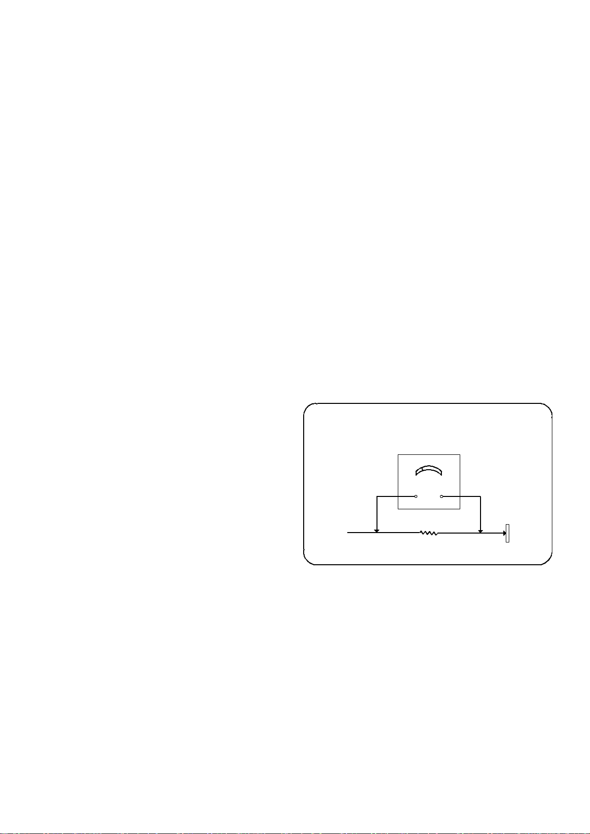
HOT CHECK CIRCUIT
A.C. Voltmeter
To Instrument's
exposed
metallic parts
2K ohm 10W
Water Pipe
(Earth)
Fig.1
X-Radiation Warning
1. The potential sources of X-Radiation in TV sets are the high
voltage section and the picture tube.
2. When using a picture tube test jig for service ensure that the jig
is capable of handling 28kV without causing X-Radiation.
NOTE : It is important to use an accurate periodically calibrated high
voltage meter
1. Set the brightness to minimum.
2. Measure the high voltage. The meter should indicate 27kV _1kV
at zero beam current if the meter indication is out of tolerance,
immediate service and correction is required to prevent the
possibility of premature component failure.
3. To prevent an X-Radiation possibility, it is essential to use the
specified tube.

Location Of Controls
FOCUS
Fig.2
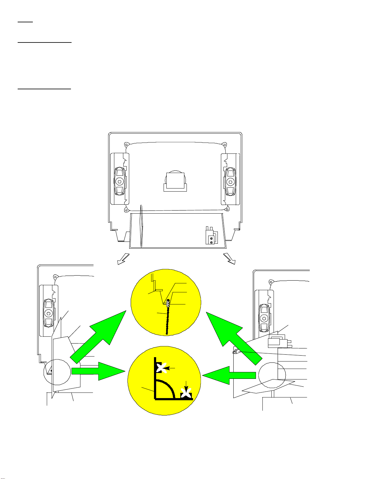
Service Hints
How to remove the rear cover
i. Remove the 5 fixing screws (A) as shown in Fig.3/Fig.4.
SCREEN
SCREW
Fig.4
SCREWS (A)
Fig.3.
How to move the chassis into the Service position
NOTE: To place the chassis into the advised service position the T.V. must be on the T.V. stand provided with the set.
1. To place the chassis into service position hold and lift the rear of the E-PCB chassis and gently pull the chassis toward you as shown in Fig.5.
B-PCB service position.
i. Release the respective wiring clips and rotate the chassis horizontally through 90_ anti-clockwise, then lift the front of the chassis as shown in
Fig.6.
ii. Insert the bead clamper located in the bottom left hand corner of the cabinet (Fig.8.) into the chassis frame shown in Fig.9.
iii. After servicing ensure all wiring is returned to its original position before returning the receiver to the customer.
E-PCB service position.
i. Release the respective wiring clips and rotate the chassis horizontally through 180_ anti-clockwise, the lift the FBT side of the chassis as shown
in Fig.7.
ii. Insert the bead clamper located in the bottom left hand corner of the cabinet (Fig.8.) into the chassis frame shown in Fig.9
iii. After servicing ensure all wiring is returned to its original position before returning the receiver to the customer.
Fig.5
CABINET
E - PCB
B - PCB
T.V. STAND
Fig.6.
.
BEAD
CLAMPER
CHASSIS
FRAME
E - PCB
Fig.8.
MAINS
SWITCH
INSERT
BEAD
CLAMPER
B - PCB
T.V. STAND
Fig.7.
Fig.9.
4
TX-21AD2
Service Mode
The remote control is used for entering and storing adjustments, with the exception of cut-off adjustments which must always be done prior to service
adjustment. Perform adjustments in accordance with screen display. The display on the screen also specifies the CCU variants as well as the approx.
setting values. The adjustment sequence for the service mode is indicated below.
1. Set the Bass to maximum position, set the Treble to minimum
position, press the F button followed by the Volume down on the
customer controls at the front of the TV and at the same time
press the Reveal button on the remote control, this will place the
TV into the Service Mode.
2. Press the RED / GREEN buttons to step down / up through the
functions.
NOTE: This TV also has the option of using a Memory Pack which enables you to copy the preset TV channels and analogue levels into the Memory
Pack and then upload them onto another EURO-2 TV set.
3. Press the YELLOW / BLUE buttons to alter the function values.
4. Press the STORE button on the preset panel after each
adjustment has been made to store the required values.
5. To exit the Service Mode press the Normalisation button.
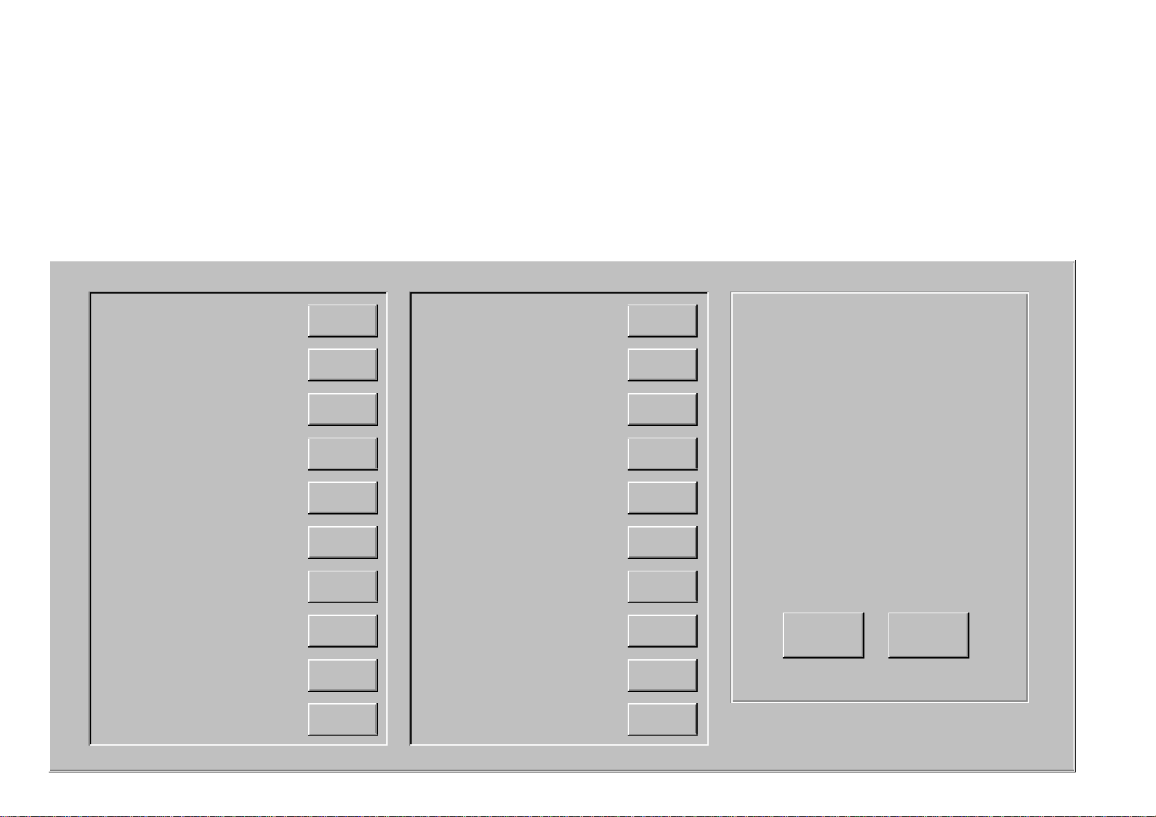
Using the Memory Pack
TV to Memory Pack process
1. Plug the memory pack into the lower of the two 21 pin terminals
at the back of the TV and switch the TV on. If the TV has only
one 21 pin connector then this will be able to accept the memory
pack.
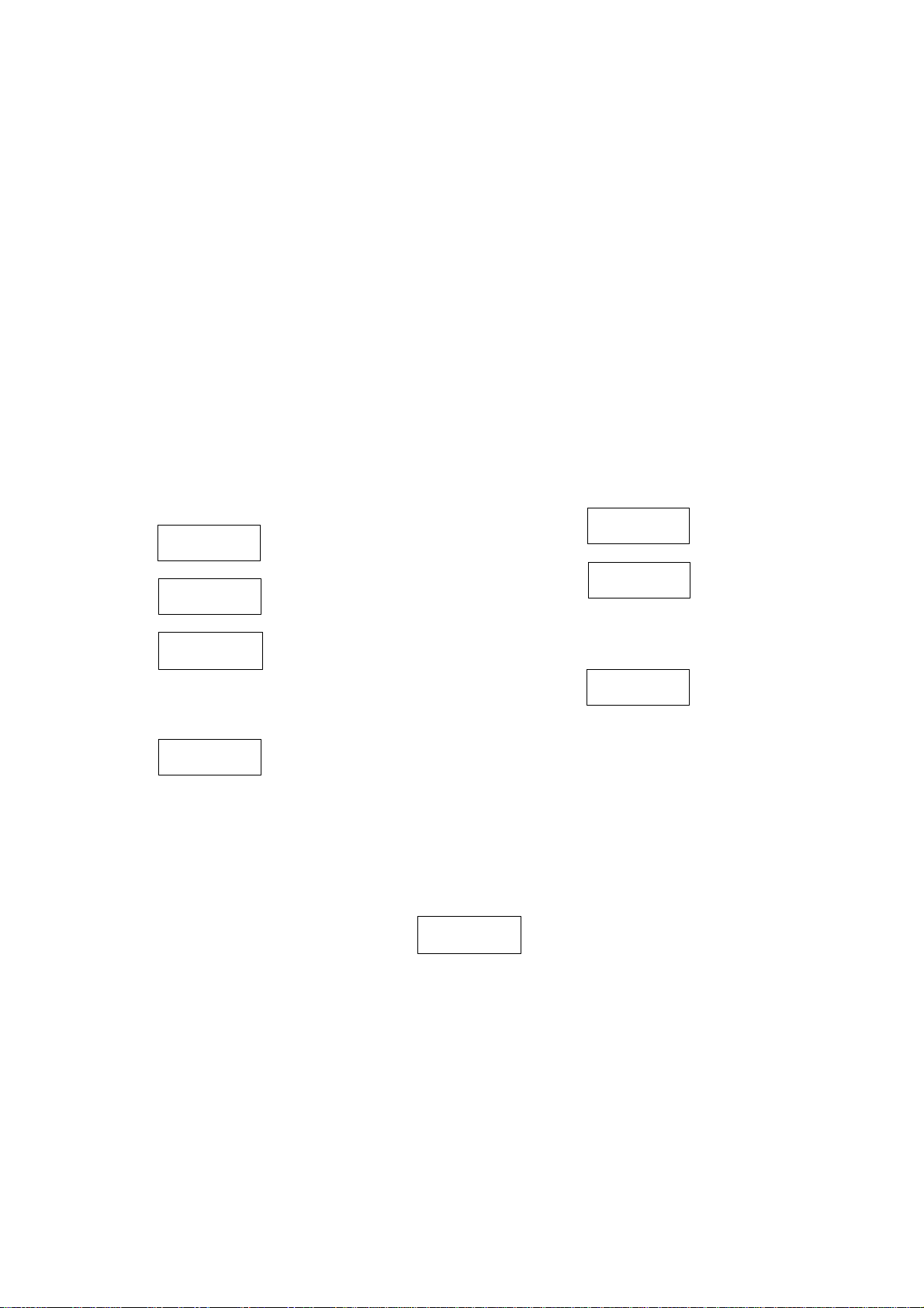
2. Go into the Service Mode as explained above. The screen will
show:-
Program
External>>TV
Program
TV>>External
3. Press the blue button on
the remote control. The
screen will show:-
4. Press the STORE button
on the TV. The screen will
show:-
Storing
1. Plug the memory pack into the lower of the two 21 pin terminals
at the back of the TV and switch the TV on. If the TV has only
one 21 pin connector then this will be able to accept the memory
pack.
2. Go into the Service Mode as explained above. The screen will
show:-
Program
External>>TV
Loading
4. All the tuning information stored inside the Memory Pack will
now be transferred to the TV. This process will take 2-3 minutes
to complete and when finished the screen will show:-
3. Press the STORE button
on the TV. The screen will
show:-
5. All the tuning information stored inside the TV will now be
transferred to the Memory Pack. This process will take 2-3
minutes to complete and when finished the screen will show:-
OK!
Memory Pack to TV Process
5. The tuning information from the Memory Pack has now been
copied into the TV
6. To exit from the Service Mode switch off the TV.
7. The process has now been completed and the Memory Pack
can now be removed.
OK!
Errors
If an error occurs while using the Memory Pack the TV will detect this and the screen will show:-
Program
Error!
If this happens then switch off the TV and repeat the process that was being used. If the errors continue to occur then check the connectors between
the TV and the memory pack and check the 9V battery inside the memory pack.
5

TX-21AD2
VIF
Video AV
Dolby IC
Dolby IC
MSP
P
P SBLED
P OFF
P RAM
SELF CHECK
Self check is used to automatically check the Bus lines and Hexadecimal code of the TV set.
To enter the Self Check mode press Function down button, on the Preset Panel, at the same time pressing the Status button, on the Remote Control,
and the screen will show:-
Tuner
1
2
3
4
5
6
7
8
9
10
ok
ok
EEPROM
ok
Sound AV
- -
switch1
ok
switch1
VDP
ok
TPU
ok
ok
- -
Dolby Sub
- -
for L/R
11
12
13
14
15
16
17
18
19
20
If the CCU ports have been checked and found to be incorrect then "--" will appear in place of "OK".
- -
for C/R
P S MODE
ok
P. TA0
ok
P. TA1
ok
ok
P. TA2
P. TA3
ok
P SDA
ok
ok
P SCL 3
ok
P SCL4
ok
21
22
23
24
ok
ok
ok
ok
Hex codes
06
CE
34
94
85
P DEFL
Adjustment Procedure
Item/Preparation Adjustments
+B SET-UP
1. Receive a window pattern
2. Set the controls:
Brightness minimum
Contrast minimum
Volume minimum
RF AGC
1. Receive a test pattern.
2. Connect an oscilloscope between the tuner
RF AGC and ground.
3. Set the oscilloscope gain range to 1V/div.
CUT OFF
1. Receive a window pattern.
2. Degauss the tube externally.
3. Set the TV into Service Mode 1.
4. Select Cutoff DC mode.
1. Set the +B voltage up as follows:
Adjust R811 so that B2 shows 130V +/- 1V
2. Confirm the following voltages.
B1 200 +/- 10V B6 12 +/- 0.5V
B3 27 +/- 1V B7 5 + 0.1/-0.25V
B4 41.0 +/- 1V B8 5 +/- 0.25V
B5 15.5 +/- 1V U33 31 +/- 1V
1. Check that the noise becomes large when the RF AGC VR
R126 is turned counterclockwise. After the check turn it clockwise.
2. Gradually turn the RF AGC VR anti-clockwise, and set the
RF AGC VR to the point where the RF AGC voltage is just falling to a
point where this voltage drops by 0.2V from the maximum value.
1. Confirm then value is 128 and select Ug2 mode noting colour with
largest value
2. Turn the screen VR until a colour reaches 20~30.
3. Connect an oscilloscope to the cathode with the biggest value
colour.
4. Select Cutoff DC mode and adjust Cutoff pulse to 159V +/- 5V.
5. Disconnect the oscilloscope and adjust the screen to whichever colour
reaches 70 +/- 30 first.
6

TX-21AD2
Alignment Settings (The figures used below are nominal and used for representative purposes only)
Alignment Function TX-21AD2 Settings / Special features
1. Vertical amplitude V-AMP
063
2. Vertical symmetry V-SYM
002
3. Vertical linearity V-LIN
-020
4. Vert. D.C. Vert. D.C.
000
5. V-Pos. V. Pos
005
6. Horizontal amplitude H-AMP
-044
7. Horizontal position H-POS
542
8. Text Position TEXT POSITION
049
9. EW-amplitude E-W AMP 1
-059
10. EW-amplitude E-W AMP 2
044
Optimum setting
Optimum setting
Optimum setting
No Adjustment
Optimum setting
Optimum setting
Optimum setting
Optimum setting
Optimum setting
Optimum setting
11. Trapezium-comp TRAPEZ 1
000
12. Trapezium- comp TRAPEZ 2
-009
13. Colour VCO Colour VCO
006
14. Cut-off DC Cut-off DC
050
Ug 2 Test
15. Ug2 Test
16. Cutoff Cutoff
17. White White
094 044 020
057 064 056
200 255 246
Optimum setting
Optimum setting
Press either Blue or Yellow buttons to effect
automatic adjustment
No Adjustment
Select Cutoff DC in Service Mode mode and
confirm the value is 128. Select Ug 2 Test noting
colour with largest value, adjust on FBT until a
colour reaches 20 ~ 30. Connect an
oscilloscope to the cathode of the biggest value
colour, select Cutoff DC mode and adjust get
Cutoff pulse voltage to 159_5V. Disconnect the
oscilloscope and adjust the screen to whichever
colour reaches 70_30 first.
Press the GREEN button to step through the
settings. Adjust for optimum.
Press the GREEN button to step through the
settings. Adjust for optimum.
7
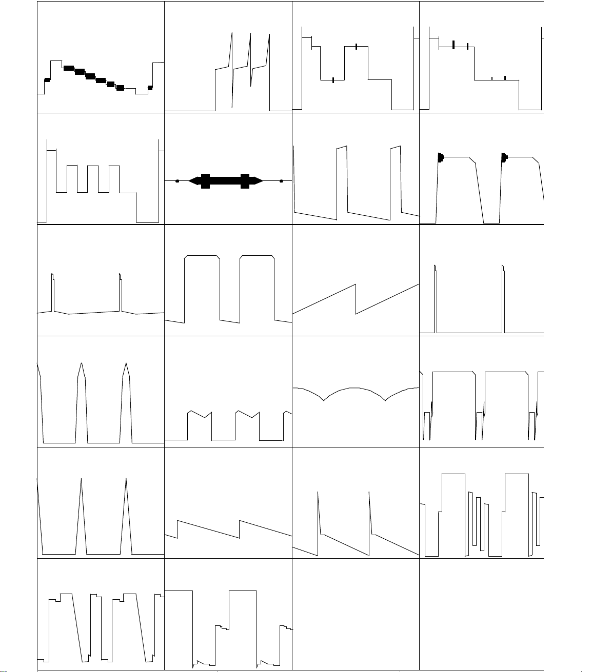
PIN 42
10u
PIN 6 E8
50u sec/div
PIN 5 E8
10u
PIN 3 E8
10u
PIN 4 E8
10u
PIN 6
5m sec/div
COLLECTOR
64u sec/div
PIN 44
10u
(Chroma)
PIN 3
5u sec/div
BASE Q503
20u sec/div
PIN 7
2u sec/div
PIN 6
5m sec/div
PIN 7
5m sec/div
PIN 18
5u sec/div
PIN 34
5m sec/div
BASE
20u sec/div
PIN 8
64u sec/div
RED DRIVE
EMITTER
80v
PIN 1
5m sec/div
GREEN DRIVE
EMITTER Q352
100v
PIN 5
5m sec/div
BLUE DRIVE
EMITTER Q353
120v
 Loading...