

PANASONIC TX-20LA1Z User Manual
1
2 3
4
5 6
7
8 9
C
0
Operating Instructions
LCD TV
Model No.
TX-17LA1M
TX-20LA1M
TX-17LA1Q
TX-20LA1Q
TX-17LA1Z
TX-20LA1Z
TX-17LA1X
TX-20LA1X
TC-17LA1H
TC-20LA1H
LCD TV shown above is model TX-20LA1.
Please read these instructions before operating your set and retain them for future reference.
English
TQBC0673-1

Dear Panasonic Customer
Welcome to the Panasonic family of customers. We hope that you will have
many years of enjoyment from your new LCD TV.
To obtain maximum benefit from your set, please read these Instructions
before making any adjustments, and retain them for future reference.
Retain your purchase receipt also, and note down the model number and
serial number of your set in the space provided on the rear cover of these
instructions.
Table of Contents
Warnings and Precautions..................................... 3
TV Games / Home Computers .............................. 3
Cabinet and LCD panel care ................................. 4
Preparation ............................................................ 4
Receiver Location.................................................. 4
Optional External Equipment ................................. 4
For optimum quality picture ................................... 4
How to use the LCD stand..................................... 4
Before Operating This Set...................................... 5
Supplied Accessories ............................................ 5
Fitting remote control batteries .............................. 5
Battery cautions ..................................................... 5
Antenna cover removal and fitting ......................... 6
Cable cover removal and fitting ............................. 6
Quick Start Guide.................................................... 7
Connections ............................................................ 8
How to connect the input terminals ....................... 8
Connecting Headphones / Earphones................... 9
Basic controls ....................................................... 10
Top panel controls and Remote control ............... 10
Using the On Screen Displays ............................. 12
SETUP MENU......................................................... 13
TUNING MENU....................................................... 14
Channel Selection ............................................... 14
AUTO TUNE ........................................................ 16
AUTO TUNE (via top panel) ................................ 16
MANUAL TUNE ................................................... 17
MANUAL TUNE (via top panel) ........................... 17
PICTURE ................................................................ 18
SOUND ................................................................... 19
Stereo Bilingual Sound Selection ........................ 20
ASPECT Controls.................................................. 21
Advanced Remote Control Operation ................. 22
TELETEXT........................................................... 22
VCR / DVD Operation.......................................... 24
Manufacturer setting ............................................ 25
Channel Allocation................................................ 26
Troubleshooting.................................................... 27
Maintenance .......................................................... 27
Specifications......................................... Back cover
2
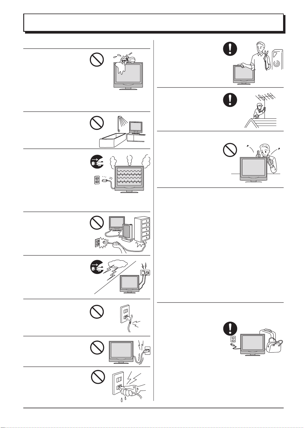
W arnings and Precautions
• This TV set is designed to operate on DC 15V.
• To prevent damage which
might result in electric
shock or fire, do not
expose this TV set to rain
or excessive moisture.
This TV must not be
exposed to dripping or
splashing water, and objects filled with liquid, such as
vases, must not be placed on top of or above the TV.
• DO NOT use this unit near
water. (Near a bath tub,
etc.)
•
Unplug the power cord in
the event of any malfunction
(screen goes blank, no
sound, odd sounds, smoke
or unusual odours coming
from the unit).
Unplug the power cord if
foreign matter or water falls into the unit, or if the unit
is dropped or the cabinet is damaged.
• TAKE CARE NOT to
damage the power cord.
• DO NOT touch the aerial
cable and this unit when
there is lightning.
• DO NOT use if the power
cord or power plug is
damaged, or if the plug
does not fit tightly into the
socket.
• DO NOT use at a voltage
other than indicated.
• DO NOT touch the power
plug if your hands are wet.
• Turn the power “Off”
before connecting other
electrical equipment.
• Ask your sales outlet to
install the aerial.
• WARNING : HIGH VOLTAGE!!!
Do not remove the rear
cover as live parts are
accessible when it is
removed. There are no
user serviceable parts
inside.
• TV Games / Home Computers
Extended use of TV games or home computers with
any television set can cause a permanent ‘shadow’
on the screen. This type of irreversible LCD panel
damage, can be limited by observing the following
points:
• Reduce the brightness and contrast levels to a
minimum viewing level.
• Do not allow a still picture to be displayed for an
extended period, as this can cause a permanent afterimage to remain on the LCD TV screen.
• Examples of still pictures include logos, video games,
computer images, teletext and images displayed in
16:9 mode.
• This type of LCD panel damage, is not an operating
defect, and as such is not covered by the Panasonic
warranty.
• The On/Off switch on this model does not fully
disconnect the TV from the mains supply.
Remove the mains plug
from the wall socket
before connecting or
disconnecting any leads,
or if the TV set is not used
for a prolonged period of
time.
Note:
• If the set is not switched off when the TV station stops
transmitting, it will automatically go to stand-by mode
after 30 minutes. This function will not operate when
the TV is in AV mode.
3
Warnings and Precautions
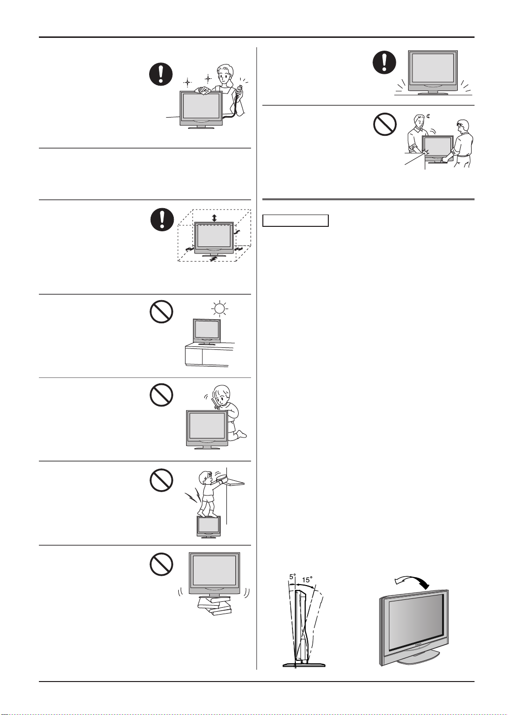
• Cabinet and LCD panel care
Remove the mains plug
from the wall socket. The
cabinet and LCD panel
can be cleaned with a soft
cloth moistened with mild
detergent and water.
Do not use solutions
containing benzol or petroleum.
• When ambient temperature is cool, the picture may
take a short time to reach normal brightness, but this
is not a malfunction. (After brief moment, the picture
will have normal brightness.)
• Adequate ventilation is
essential to prevent failure
of electrical components,
we recommend that a gap
of at least 10cm is left all
around this television
receiver even when it is placed inside a cabinet or
between shelves.
• A void exposing the TV set
to direct sunlight and other
sources of heat. To
prevent fire, never place
any type of candle or
naked flame on top or
near the TV set.
• DO NOT insert foreign
objects (metal or easily
flammable objects).
• DO NOT stand, or place
heavy objects on the unit.
Particular care should be
taken by families with
small children.
• DO NOT place in an
unstable location.
• Place in a safe location.
• DO NOT jolt the unit.
Preparation
• Receiver Location
Locate for comfortable viewing. Avoid placing where
sunlight or other bright light (including reflections) will
fall on the screen.
Use of some types of fluorescent lighting can reduce
remote control transmitter range.
Adequate ventilation is essential to prevent internal
component failure. Keep away from areas of excessive
heat or moisture.
To insure optimum picture do not position magnetic
equipment (motors, fans, other speakers, etc.) nearby .
• Optional External Equipment
The Video/Audio connection between components can
be made with shielded video and audio cables. For
best performance, we recommend 75 ohm coaxial
aerial cable is used. Cables are available from your
dealer or electronic supply store.
Before you purchase any cables, be sure you know
what type of output and input connectors your various
components require. Also determine the length of cable
you’ll need.
• For optimum quality picture
When the LCD is exposed to light from outdoors or
lighting fixtures, high-contrast pictures may not be
displayed clearly. Turn off florescent lamps near the
LCD and place in a location not exposed to outdoor
light.
• How to use the LCD stand
Adjust the stand to your desired angle. The stand angle
can be adjusted between 5 ° forward to 15 ° back.
4
Before Operating This Set
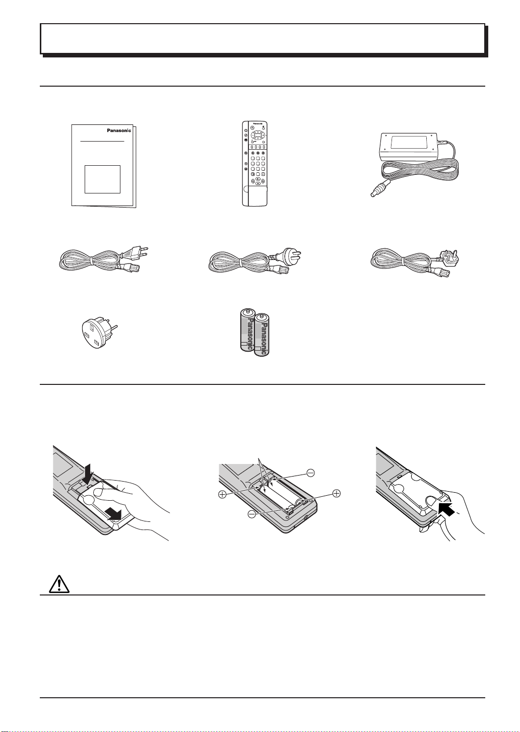
Supplied Accessories
Check the accessories before installations.
• Operating Instruction book • Remote Control Transmitter • AC Adaptor
PICTURE
SOUND
SET UP
TV/AV
F.P. INDEX HOLD
TV/TEXT
1
2 3
SURROUND
4
5 6
ASPECT
7
8 9
VCR
0
• Mains Lead
TX-17LA1M, TX-20LA1M
TX-17LA1Q, TX-20LA1Q
TX-17LA1Z, TX-20LA1Z
TX-17LA1X, TX-20LA1X
TC-17LA1H, TC-20LA1H
• AC Plug Adaptor
TX-17LA1X, TX-20LA1X only
• Batteries for the Remote Control
Transmitter (2 × R6 (AA) size)
Fitting remote control batteries
Open the cover.
1
Apply slight downward
pressure while pulling
towards the bottom.
Do not use rechargeable (Ni-Cd) batteries.
They are different in shape and performance and may fail to ensure correct operation.
Batteries: Use two “R6 (AA)” size batteries.
2
Insert the batteries ensuring the correct polarities.
This is identifiable by the “+” and “-” symbols on
the batteries and inside the battery compartment.
Two “R6 (AA)” size
3 Replace the cover.
Battery cautions
The incorrect use of batteries can cause electrolyte leakage which will corrode the Remote Control or cause the
batteries to burst.
Observe the following precaution:
1. Batteries shall always be replaced as a pair. Always use new batteries when replacing the old set.
2. Do not combine a used battery with a new one.
3. Do not mix battery types (example:“Zinc Carbon” with “Alkaline”).
4. Do not attempt to charge, short-circuit, disassemble, heat or burn used batteries.
5. Battery replacement is necessary when remote control acts sporadically or stops operating the TV set.
5

Before Operating This Set
Antenna cover removal and fitting
TX-17LA1, TC-17LA1 TX-20LA1, TC-20LA1
Removal Removal
1
2
1. Grasp the cover at the
bottom end and initially
remove by pulling slightly
toward yourself.
2. Slowly pull out in the
downward direction.
Fitting Fitting
1
2
1. Insert the claws (at 4
points) at the top end.
2. Push it until click.
1
Cable cover removal and fitting
Removal Fitting
2
1
1. Disengage the claws at the
uppermost end.
2. Slowly pull out in the upward
direction.
1. Grasp the opening and
initially pull the cover
slightly towards yourself to
1
2
2
2
disengage the claws (at 2
points on both the left and
right).
2. Slowly pull out in the
downward direction.
1. Insert the claws (at 4
points) at the top end.
2. Push it until click.
1. Insert the claws (at 2 points) at
the bottom.
2. Push it until click.
1
Note:
Depending on the type of cable used it may not be possible to close the cover. In such cases the cable may be
routed through the antenna cover.
6
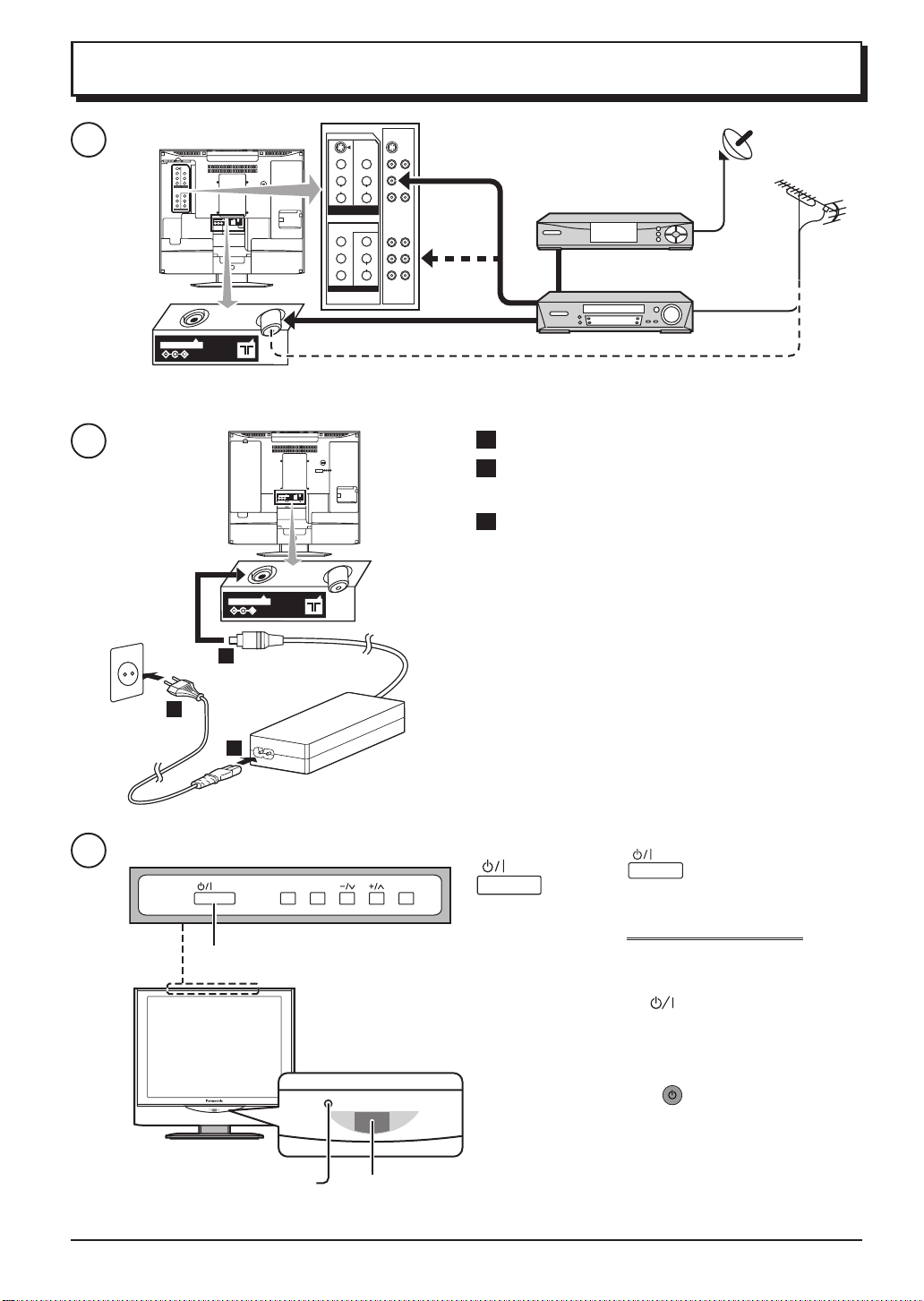
Quick Start Guide
1
S - VIDEO
VIDEO
VIDEO
MONO
L
L
AUDIO
AUDIO
R
R
MONITOR
AV1 IN
OUT
COMPONENT VIDEO INPUT
Y
VIDEO
MONO
P
L
B
AUDIO
P
R
R
AV2 IN
S - VIDEO
VIDEO
VIDEO
MONO
L
AUDIO
AUDIO
R
MONITOR
AV1 IN
OUT
COMPONENT VIDEO INPUT
Y
VIDEO
MONO
P
B
AUDIO
P
R
AV2 IN
L
R
L
R
OR
SET TOP BOX
VCR / DVD recorder
OR
DC IN 15V
Plug in aerial and connect ancillary equipment
2
1 Connect the mains lead to the AC Adaptor.
2 Connect the AC Adaptor DC plug to the DC IN
socket.
3 Plug into household mains socket.
• Be sure to use the mains lead and AC adaptor
included in the accessories.
DC IN 15V
• Do not use the AC adaptor for other than the
specified equipment.
• Unplug the AC adaptor if it is not used for long time.
2
• Do not place any objects on the AC adaptor.
• Do not use the AC adaptor outdoors.
• Do not attempt to repair the AC adaptor if it is
3
broken or malfunctioning. Refer the servicing to the
service representative.
1
• Do not try to open the AC adaptor.
• Do not use water or wet cloth for cleaning the AC
adaptor.
3
STR F TV/AV
Main Power switch
LED Indicator
Adaptor
connection only : Orange
Power Indicator
STB : Red
On : No Light
Remote control
signal sensor
Press the switch on the LCD TV to
turn the set on.
IMPORTANT NOTES
There are two ways to switch the TV set to
stand-by mode.
(A) Press the
switch on the LCD TV and
check RED LED is lit.
OR
(B) Press the
Stand-by button on the
remote control.
The TV set can be switched on by the remote
control if it was switched to stand-by using
method (A) or method (B).
7
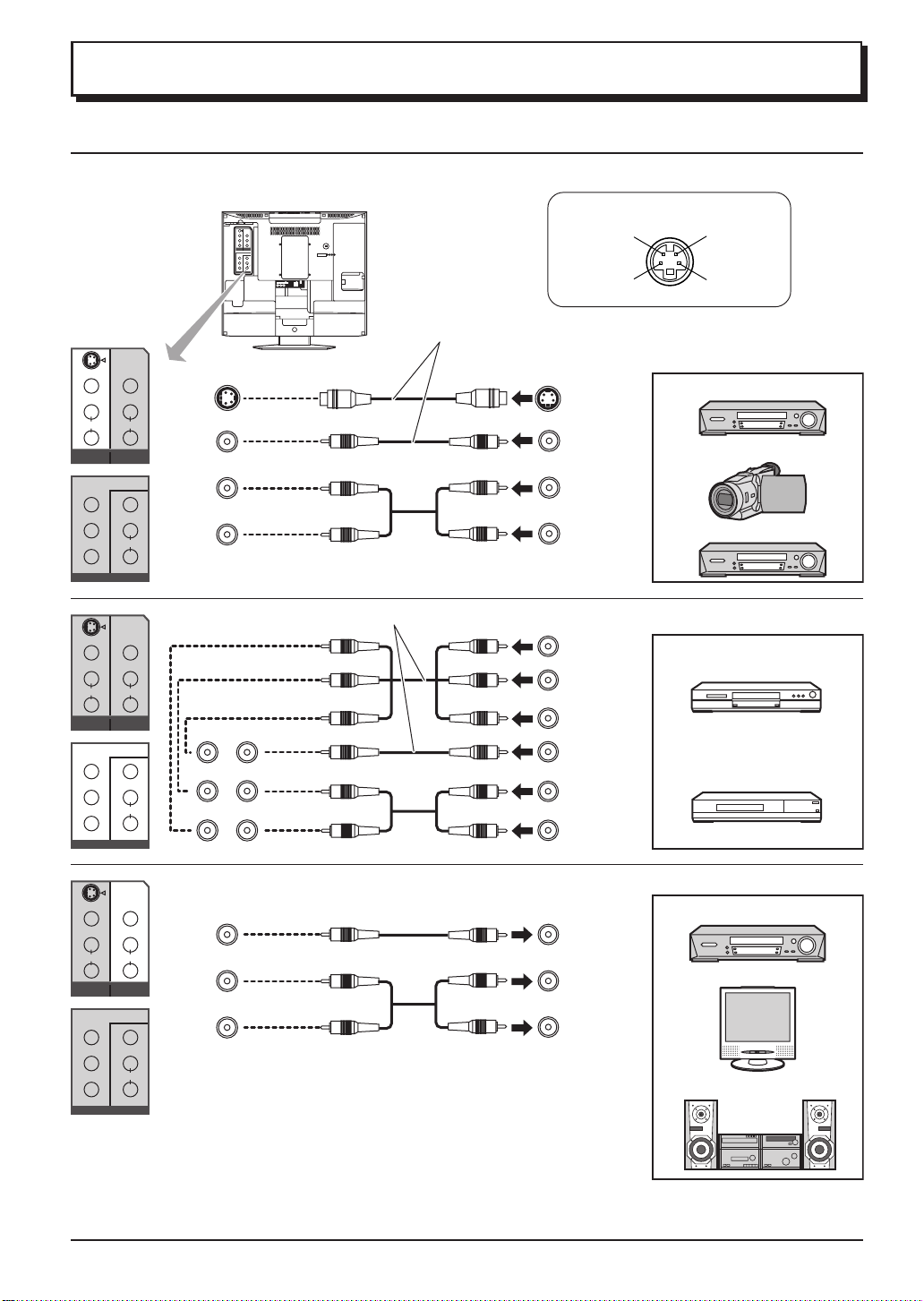
Connections
How to connect the input terminals
Connects VCRs and other peripheral equipment
S - VIDEO
VIDEO
VIDEO
MONO
L
L
AUDIO
AUDIO
R
R
COMPONENT VIDEO INPUT
Y
VIDEO
MONO
P
L
B
AUDIO
P
R
R
AV2 IN
Connect the S-VIDEO or VIDEO terminal.
S - VIDEO
VIDEO
VIDEO
MONO
L
L
AUDIO
AUDIO
R
R
MONITOR
AV1 I N
OUT
COMPONENT VIDEO INPUT
Y
VIDEO
MONO
P
L
B
AUDIO
P
R
R
AV2 I N
AV1 IN
Connect the Y/PB/PR or VIDEO terminals.
S - VIDEO
VIDEO
VIDEO
MONO
L
L
AUDIO
AUDIO
R
R
MONITOR
AV1 I N
OUT
COMPONENT VIDEO INPUT
Y
VIDEO
MONO
P
L
B
AUDIO
P
R
R
AV2 I N
S - VIDEO
VIDEO
VIDEO
MONO
L
L
AUDIO
AUDIO
R
R
MONITOR
AV1 I N
OUT
COMPONENT VIDEO INPUT
Y
VIDEO
MONO
P
L
B
AUDIO
P
R
R
AV2 I N
AV2 IN
MONITOR
OUT
• S-Video socket information
AV1 S-V ideo 4 pin socket
Chrominance
in
Chrominance
earth
S VIDEO
OUT
VIDEO
OUT
L
AUDIO
R
OUT
COMPONENT VIDEO OUT
P
R
P
B
Y, PB, PR,
OUT
Y
VIDEO
OUT
L
AUDIO
R
OUT
VIDEO
L
AUDIO
R
Luminance
in
Luminance
earth
Example of input signal source
S VIDEO VCR
CAMCORDER
VCR
Example of input signal source
DVD
Digital TV-SET-TOP-BOX
(DTV-STB)
Example of input signal source
VCR
IN
MONITOR
IN
Amplifier to speaker system
Notes:
• Additional equipment and cables shown are not supplied with this TV set.
• Do not connect a computer with TTL output (5V) to this set.
• Select the desired VIDEO input position by pushing the TV/AV button. (see page 10, 11)
8
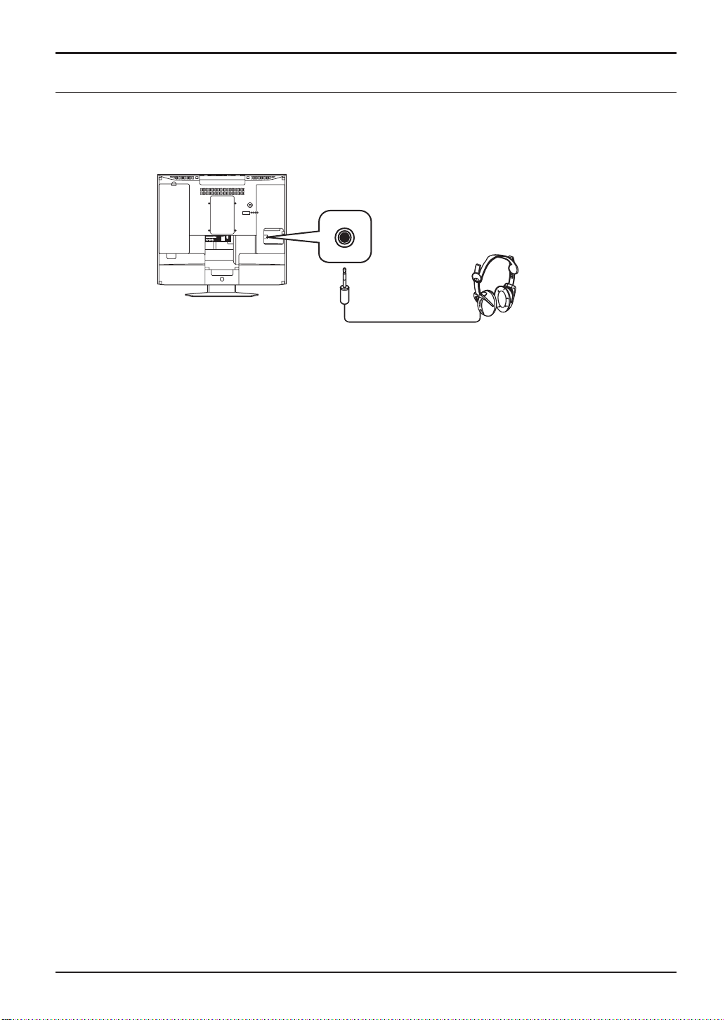
Connections
Connecting Headphones / Earphones
Connect headphones / earphones as follows.
(M3 plug)
(Not supplied)
Notes:
• The volume level of the headphones can be adjusted by selecting “HEADPHONE VOL.” from the SOUND.
• Additional equipment and cables shown are not supplied with this TV set.
9
 Loading...