

Page 1
ViV
A
TM
Operating Instructions
54” Class 1080p Plasma HDTV
(54.1 inches measured diagonally)
Model No.
TC-P54Z1
Quick Start Guide
(See page 8-24)
For assistance (U.S.A./Puerto Rico), please call:
1-877-95-VIERA (958-4372)
or visit us at www.panasonic.com/contactinfo
English
For assistance (Canada), please call:
1-866-330-0014
or visit us at www.vieraconcierge.ca
Please read these instructions before operating your set and retain them for future reference.
The images shown in this manual are for illustrative purposes only.
TQBC2488-1
Page 2
2
3
Viewing Advanced FAQs, etc.
Quick Start
Guide
VIERA Link™ is a trademark of Panasonic
Corporation.
VIERA CAST™ is a trademark of
Panasonic Corporation.
SDHC Logo is a trademark.
HD3D Sound
ViV
A
HDMI, the HDMI logo and High-Definition
Multimedia Interface are trademarks or
registered trademarks of HDMI Licensing
LLC.
Manufactured under license from
Dolby Laboratories.
Dolby and the double-D symbol are
trademarks of Dolby Laboratories.
Turn your own living room into a movie theater!
Experience an amazing level of multimedia excitement
Page 3
3
Viewing Advanced FAQs, etc.
Quick Start
Guide
HD3D Sound
ViV
A
Contents
Please read before using the unit
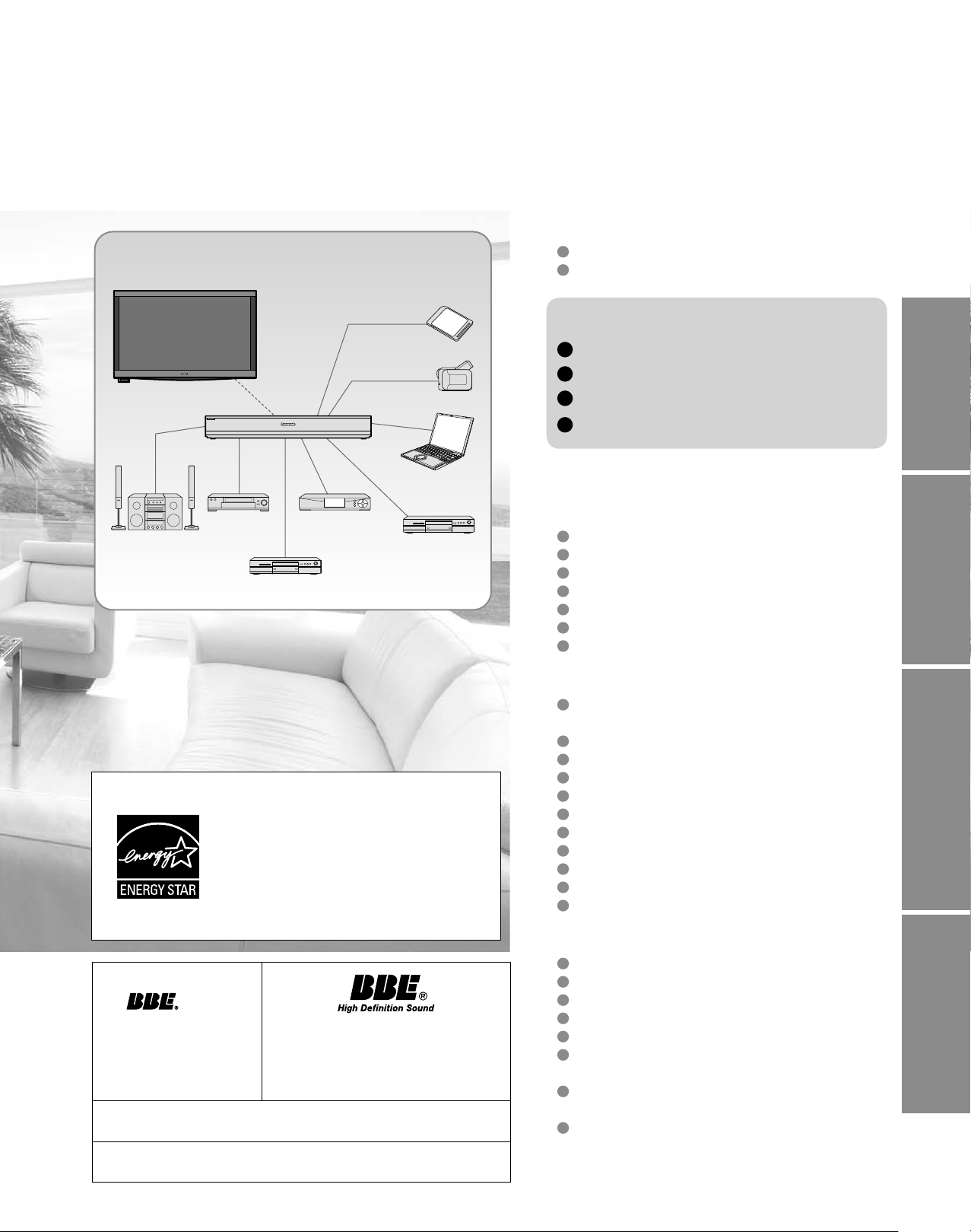
Enjoy rich multimedia
Amplifier
Home theater
system
SD memory card
Camcorder
Personal
computer
VCR
DVD recorder/
Blu-ray Disc recorder
This product qualifies for ENERGY
STAR in the “Home Use” setting and this
is the setting in which energy savings
will be achieved. Any modifications to
the “Home Use” setting or other factory
default settings could result in greater
energy consumption beyond levels that
meet ENERGY STAR qualifications.
Set Top Box
DVD player/
Blu-ray Disc player
Safety Precautions ·······································4
Notes ····························································7
Quick Start Guide
Accessories/Optional Accessory ·····8
Basic Connection ···························15
Identifying Controls ························ 19
First Time Setup·····························21
Enjoy your TV!
Basic Features
Watching TV ···············································25
Using VIERA TOOLS ································· 27
Viewing from an SD Card ··························28
Watching Videos and DVDs ·······················32
VIERA CASTTM ···········································34
Network Camera ········································ 36
Displaying PC Screen on TV ·····················38
Advanced Features
How to Use Menu Functions
(picture, sound quality, etc.) ·······················40
VIERA LinkTM “HDAVI ControlTM” ················44
Network setting ·········································· 50
VIERA CAST setting ··································52
Lock ··························································· 54
Editing and Setting Channels·····················56
Closed Caption ·········································· 58
Input Labels ··············································· 59
Using Timer ················································ 60
Remote control registration ························61
Recommended AV Connections ················ 62
Manufactured under
license from BBE Sound,
Inc.
HDAVI Control™ is a trademark of Panasonic Corporation.
The WiHD™ logo is licensed for use by WirelessHD, LLC.
Licensed by BBE Sound, Inc. under
one or more of the following US
patents: 5510752, 5736897.
BBE and BBE symbol are registered
trademarks of BBE Sound, Inc.
FAQs, etc.
Ratings List for Lock ··································63
Technical Information ································· 64
Care and Cleaning ·····································68
Specifications ············································· 69
FAQ ···························································· 70
Limited Warranty
(for U.S.A. and Puerto Rico only)···············72
Customer Services Directory
(for U.S.A. and Puerto Rico) ······················73
Limited Warranty (for Canada) ···················74
Page 4
4
5
Safety Precautions
WARNING: To reduce the risk of fire or electric shock, do not expose this apparatus to rain or moisture.
Do not place liquid containers (flower vase, cups, cosmetics, etc.) above the set
(including on shelves above, etc.).
Important Safety Instructions
1) Read these instructions.
2) Keep these instructions.
3) Heed all warnings.
4) Follow all instructions.
5) Do not use this apparatus near water.
6) Clean only with dry cloth.
7) Do not block any ventilation openings. Install in
accordance with the manufacturer’s instructions.
8) Do not install near any heat sources such as radiators,
heat registers, stoves, or other apparatus (including
amplifiers) that produce heat.
9) Do not defeat the safety purpose of the polarized or
grounding-type plug. A polarized plug has two blades with
one wider than the other. A grounding type plug has two
blades and a third grounding prong. The wide blade or the
third prong are provided for your safety. If the provided
plug does not fit into your outlet, consult an electrician for
replacement of the obsolete outlet.
10) Protect the power cord from being walked on or pinched
particularly at plugs, convenience receptacles, and the
point where they exit from the apparatus.
11) Only use attachments / accessories specified by the
manufacturer.
12) Use only with the cart, stand, tripod,
bracket, or table specified by the
manufacturer, or sold with the
apparatus. When a cart is used,
use caution when moving the cart /
apparatus combination to avoid injury
from tip-over.
13) Unplug this apparatus during lightning storms or when
unused for long periods of time.
14) Refer all servicing to qualified service personnel. Servicing
is required when the apparatus has been damaged in any
way, such as power-supply cord or plug is damaged, liquid
has been spilled or objects have fallen into the apparatus,
the apparatus has been exposed to rain or moisture, does
not operate normally, or has been dropped.
15) To prevent electric shock, ensure the grounding pin on the
AC cord power plug is securely connected.
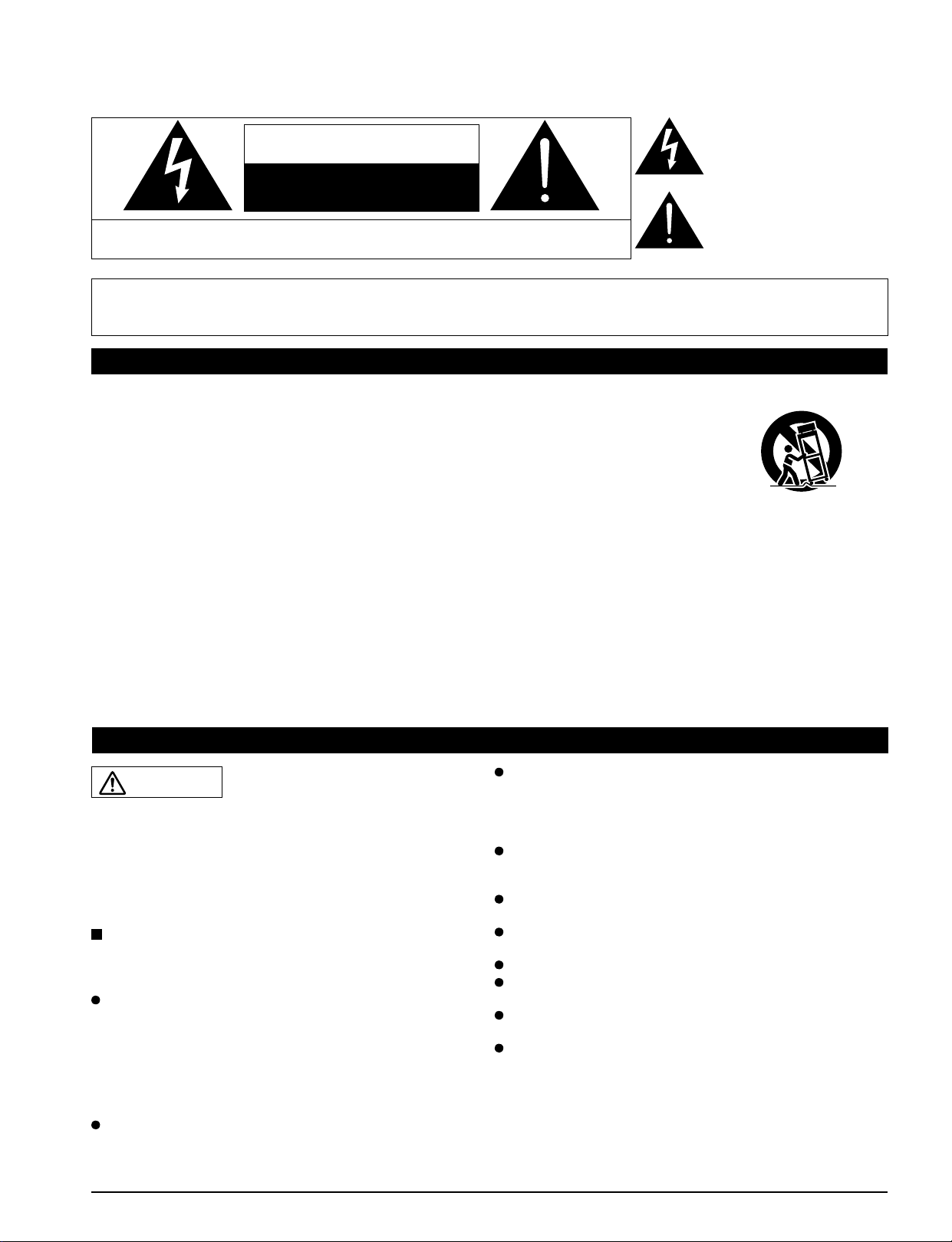
CAUTION
RISK OF ELECTRIC SHOCK
DO NOT OPEN
WARNING: To reduce the risk of electric shock, do not remove cover or back.
No user-serviceable parts inside. Refer servicing to qualified service personnel.
The lightning flash with
arrowhead within a triangle is
intended to tell the user that
parts inside the product are a
risk of electric shock to persons.
The exclamation point within
a triangle is intended to
tell the user that important
operating and servicing
instructions are in the papers
with the appliance.
WARNING/CAUTION
WARNING
Small parts can present choking hazard if accidentally
swallowed.
Keep small parts away from young children.
Discard unneeded small parts and other objects, including
packaging materials and plastic bags/sheets to prevent
them from being played with by young children, creating
the potential risk of suffocation.
Set up
This Plasma TV may fall and can cause personal injury or
even death if not installed correctly. To prevent personal injury
or death, follow these warnings:
Install the Plasma TV in accordance with the
manufacturer’s recommended pedestal or stand,
corresponding hardware and installation instructions.
This Plasma TV is for use only with the following optional
accessories. Use with any other type of optional accessories
may cause instability. The following accessories are
manufactured by Panasonic Corporation.
• Wall-hanging bracket (Vertical) TY-WK5P1SW
Be sure to ask a qualified technician to carry out the
installation and set-up.
Two or more people are required to install or remove the
television.
Some wall mounts (wall-hanging brackets) are not
designed to be mounted to walls with steel studs or old
cinder block constructions.
Ask your dealer or licensed contractor to properly secure the
wall-hanging bracket.
Do not place the Plasma TV or its stand on a sloped or
unstable surface.
The Plasma TV may fall or tip over.
Do not support the Plasma TV on a non-specified
pedestal.
Do not place the Plasma TV on furniture that can easily
be used as steps, such as a chest of drawers.
Do not climb or allow children to climb on the Plasma TV
Place or install the Plasma TV where it cannot be pushed,
pulled over or knocked down.
Route all cords and cables such that they cannot be
tripped over or pulled by curious children.
Do not place any objects on top of the Plasma TV.
If water spills onto the Plasma TV or foreign objects get
inside it, a short-circuit may occur which could result in fire
or electric shock. If any foreign objects get inside the Plasma
TV, please consult an Authorized Service Center.
Page 5
5
AC Power Supply Cord
To prevent fire or electric shock:
The Plasma TV is designed to operate on a 120 V AC,
60 Hz service. Insert the power cord plug as far as it will
go into the wall socket.
If the plug is not fully inserted, heat may generate, which
could cause a fire.
Do not handle the power cord plug with wet hands.
Do not do anything that might damage the power supply
cord.
When disconnecting the power supply cord, hold the
plug, not the cord.
Handling the power supply cord
Insert the power plug fully into the socket outlet. (If the
power plug is loose, it could generate heat and cause fire.)
Ensure that the power plug is easily accessible.
Ensure the earth pin on the power plug is securely
connected to prevent electrical shock.
•
An apparatus with CLASS I construction shall be connected to
a power socket outlet with a protective earthing connection.
Do not touch the power plug with a wet hand. (This may
cause electrical shock.)
Do not use any power cord other than that provided with
this TV. (This may cause fire or electrical shock.)
Do not damage the power cord. (A damaged cord may
cause fire or electrical shock.)
Do not move the TV with the cord plugged in the socket outlet.
•
• Do not place a heavy object on the cord or place the cord
near a high-temperature object.
• Do not twist the cord, bend it excessively, or stretch it.
• Do not pull on the cord. Hold onto the power plug body
when disconnecting cord.
• Do not use a damaged power plug or socket outlet.
Radio waves
Do not place this TV in any medical institutions or
locations with medical devices.
Radio waves from this TV may interfere with the medical
devices and cause accidents due to the malfunction.
Do not use this TV near any automatic control devices
such as automatic doors or fire alarms.
Radio waves from this TV may interfere with the automatic
control devices and cause accidents due to the malfunction.
Keep the RF remote control, Tuner Box and Wireless Unit
away at least 8.7 inches (22 cm) from the location where
a cardiac pacemaker is implanted.
Radio waves from this TV may interfere with the operation of
the pacemaker.
Do not disassemble the RF remote control, Tuner Box or
Wireless Unit.
It may cause troubles such as difficulties in communication.
If Problems Occur During Use
If a problem occurs (such as no picture or no sound),
or if smoke or an abnormal odor is detected from the
Plasma TV, unplug the power supply cord immediately.
Continued use of the TV under these conditions might cause
a fire or permanent damage to the TV. Have the TV evaluated
by an Authorized Service Center. Servicing of the TV by
unauthorized personnel is strongly discouraged due to its
high voltage.
If water or an object gets inside the Plasma TV, if the
Plasma TV is dropped, or if the enclosure becomes
damaged, unplug the power supply cord immediately.
A short-circuit may occur, which could cause a fire. Contact
an Authorized Service Center for an evaluation.
CAUTION
Do not cover the ventilation holes.
Doing so may cause the Plasma TV to overheat, which can
cause a fire or damage to the Plasma TV.
Leave a space of 3 15/16” (10 cm) or more at the top, left
and right, and 2 3/4” (7 cm) or more at the rear.
When using the pedestal, keep the space between the
bottom of the TV and the pedestal or stand surface clear
from objects that may obstruct ventilation.
When Moving the Plasma TV
Be sure to disconnect all cables before moving the
Plasma TV.
Moving the TV with its cables attached might damage the
cables which, in turn, can cause fire or electric shock
To prevent an electric shock, disconnect the power
plug from the wall outlet as a safety precaution before
carrying out any cleaning.
Transport only in upright position
Transporting the unit with its display panel facing upright or
downward may cause damage to the internal circuitry.
Using a dry cloth, clean any dust from the power supply
cord and plug regularly.
Build-up of dust on the power cord plug can increase
humidity, which might damage the insulation and cause a fire.
This Plasma TV radiates infrared rays;
therefore, it may affect other infrared communication
equipment. Install your infrared sensor in a place away from
direct or reflected light from your Plasma TV.
The TV will still consume some power as long as the power
supply cord is connected to the wall outlet.
Display panel is made of glass. Do not apply strong force
or impact to the display panel.
This may cause damage resulting in injury.
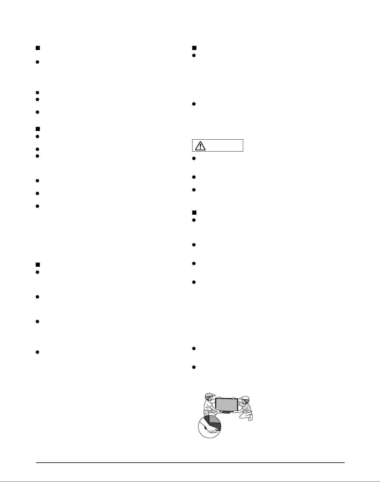
The TV is heavy. TV should be handled by 2 or more
people. Support as shown to avoid injury by the TV
tipping or falling.
When the Wireless Unit (Receiver) is attached, do not hold it.
Page 6

6
7
CEA CHILD SAFETY NOTICES: Flat panel displays are not always supported on the proper stands or
installed according to the manufacturer’s recommendations. Flat panel displays that are inappropriat ely
situated on dressers, bookcases, shelves, desks, speakers, chests or carts may fall over and may cause
personal injury or even death.
The consumer electronics industry (of which Panasonic is a member) is committed to making home
entertainment enjoyable and safe. To prevent personal injury or death, be sure to follow the following safety
guidelines:
TUNE INTO SAFETY:
• One size does NOT fit all. Follow the manufacturer’s recommendations for the safe installation and use
of your flat panel display.
• Carefully read and understand all enclosed instructions for proper use of this product.
• Don’t allow children to climb on or play with furniture and television sets.
• Don’t place flat panel displays on furniture that can easily be used as steps, such as a chest of drawers.
• Remember that children can become excited while watching a program, especially on “larger than life”
flat panel displays. Care should be taken to install the display where it cannot be pushed, pulled over,
or knocked down.
• Care should be taken to route all cords and cables connected to the flat panel display so that they
cannot be pulled or grabbed by curious children.
WALL MOUNTING: IF YOU DECIDE TO WALL MOUNT YOUR FLAT PANEL DISPLAY, ALWAYS:
• Use a mount that has been recommended by the display manufacturer and/or listed by an independent
laboratory (such as UL, CSA, ETL).
• Follow all instructions supplied by the display and wall mount manufacturers.
• If you have any doubts about your ability to safely install your flat panel display, contact your retailer
about professional installation.
• Make sure the wall where you are mounting the display is appropriate. Some wall mounts are not
designed to be mounted to walls with steel studs or old cinder block construction. If you are unsure,
contact a professional installer.
• A minimum of two people are required for installation. Flat panel displays can be heavy.
Panasonic recommends that a qualified installer perform the wall-mount
installation. See page 4.
Safety Precautions (Continued)
FCC STATEMENT
FCC Note:
This equipment has been tested and found to comply with the limits for a Class B digital device, pursuant to Part 15 of the FCC
Rules. These limits are designed to provide reasonable protection against harmful interference in a residential installation.
This equipment generates, uses and can radiate radio frequency energy and, if not installed and used in accordance with the
instructions, may cause harmful interference to radio communications. However, there is no guarantee that interference will not occur in
a particular installation. If this equipment does cause harmful interference to radio or television reception, which can be determined by
turning the equipment off and on, the user is encouraged to try to correct the interference by one or more of the following measures:
• Reorient or relocate the receiving antenna.
• Increase the separation between the equipment and receiver.
• Connect the equipment into an outlet on a circuit different from that to which the receiver is connected.
• Consult the dealer or an experienced radio/TV technician for help.
FCC Caution:
To assure continued compliance, follow the attached installation instructions and use only shielded interface cables
when connecting to computer or peripheral devices. Any changes or modifications not expressly approved by Panasonic
Corp. of North America could void the user’s authority to operate this device.
FCC RF Exposure Warning:
• This product contains wireless transmitter that complies with FCC radiation exposure limits set forth for an uncontrolled
environment.
• This product’s internal mounted wireless transmitter must not be installed or operated within 20 cm (8 inches) spacing between
all person’s body (excluding extremities of hands, wrist and feet for RF remote control) and other outside wireless transmitters.
• This product’s wireless transmitter must not be co-located or operated with any other antenna or transmitter.
FCC Declaration of Conformity
Model No. TC-P54Z1
Responsible Party: Panasonic Corporation of North America
One Panasonic Way, Secaucus, NJ 07094
Contact Source: Panasonic Consumer Electronics Company
1-877-95-VIERA (958-4372)
email: consumerproducts@panasonic.com
This device complies with Part 15 of the FCC Rules and RSS-210 of Industry Canada. Operation is subject to the following two conditions:
(1) This device may not cause harmful interference, and (2) this device must accept any interference received, including interference that
may cause undesired operation.
CANADIAN NOTICE:
For Model TC-P54Z1
This Class B digital apparatus complies with Canadian ICES-003.
Page 7
7
CEA CHILD SAFETY NOTICES: Flat panel displays are not always supported on the proper stands or
installed according to the manufacturer’s recommendations. Flat panel displays that are inappropriat ely
situated on dressers, bookcases, shelves, desks, speakers, chests or carts may fall over and may cause
personal injury or even death.
The consumer electronics industry (of which Panasonic is a member) is committed to making home
entertainment enjoyable and safe. To prevent personal injury or death, be sure to follow the following safety
guidelines:
TUNE INTO SAFETY:
• One size does NOT fit all. Follow the manufacturer’s recommendations for the safe installation and use
of your flat panel display.
• Carefully read and understand all enclosed instructions for proper use of this product.
• Don’t allow children to climb on or play with furniture and television sets.
• Don’t place flat panel displays on furniture that can easily be used as steps, such as a chest of drawers.
• Remember that children can become excited while watching a program, especially on “larger than life”
flat panel displays. Care should be taken to install the display where it cannot be pushed, pulled over,
or knocked down.
• Care should be taken to route all cords and cables connected to the flat panel display so that they
cannot be pulled or grabbed by curious children.
WALL MOUNTING: IF YOU DECIDE TO WALL MOUNT YOUR FLAT PANEL DISPLAY, ALWAYS:
• Use a mount that has been recommended by the display manufacturer and/or listed by an independent
laboratory (such as UL, CSA, ETL).
• Follow all instructions supplied by the display and wall mount manufacturers.
• If you have any doubts about your ability to safely install your flat panel display, contact your retailer
about professional installation.
• Make sure the wall where you are mounting the display is appropriate. Some wall mounts are not
designed to be mounted to walls with steel studs or old cinder block construction. If you are unsure,
contact a professional installer.
• A minimum of two people are required for installation. Flat panel displays can be heavy.
Panasonic recommends that a qualified installer perform the wall-mount
installation. See page 4.
Notes
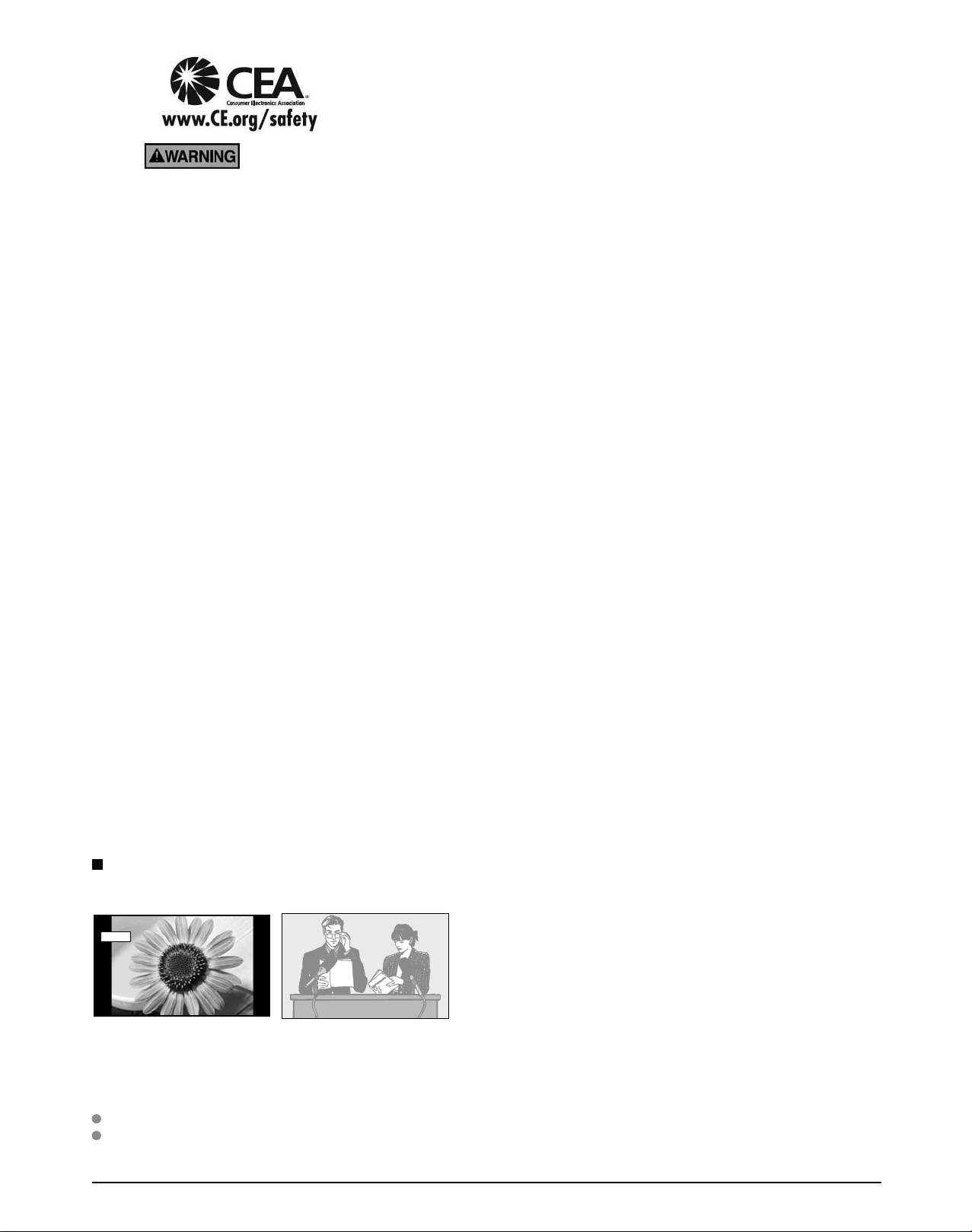
Do not display a still picture for a long time
This causes the image to remain on the plasma screen
(“Image retention”). This is not considered a malfunction and is not covered by the warranty.
4 : 3
Typical still images
Channel number and other logos
•
Image displayed in 4:3 mode
•
SD Card photo • Video game • Computer image
•
Set up
■
Do not place the unit where it’s exposed to sunlight or other bright light (including reflections).
Use of some types of fluorescent lighting may reduce the remote control’s transmission range.
12
To prevent “Image retention”, the screen saver is
automatically activated after a few minutes if no signals are
sent or no operations are performed. (p. 71)
Page 8
8
9
Quick Start
Guide
A
B
C
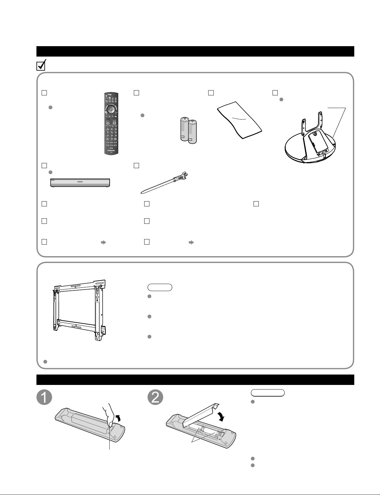
Accessories/Optional Accessory
Accessories
Check you have all the items shown.
Remote Control
Transmitter
N2QBYB000005
Batteries for the
Remote Control
Transmitter (2)
AA Battery
Pedestal
TBLX0107
Product Registration Card
(U.S.A.)
Customer Care Plan Card
(U.S.A.)
Operating Instructions
Viera Concierge and basic
instruction for HDTV
Installing the remote’s batteries
Pull open
Hook
Note the correct
polarity (+ or -).
Close
Caution
Incorrect installation may cause battery
leakage and corrosion, resulting in
damage to the remote control.
•
Do not mix old and new batteries.
•
Do not mix different battery types
(such as alkaline and manganese
batteries).
•
Do not use rechargeable (Ni-Cd)
batteries.
Do not burn or break batteries.
Do not disassemble or modify the
remote control.
Optional Accessory
Note
In order to maintain the TV’s performance and safety, be absolutely sure
to ask your dealer or a licensed contractor to secure the wall-hanging
brackets.
Carefully read the instructions accompanying the plasma TV stand or
pedestal, and be absolutely sure to take steps to prevent the TV from
tipping over.
Handle the TV carefully during installation since subjecting it to impact
or other forces may cause its panel to crack.
Wall-hanging bracket
(vertical)
TY-WK5P1SW
A
A
C
C
B
B
Accessories
How to assemble
(p. 9)
Cleaning cloth
RS232C terminal
Specifications
Wireless Unit set
p. 11
(Receiver and Transmitter)
Tuner Box
TU-Z100U
Cable clamper (2)
Speaker set
p. 10
C
A
A
R
S
E
I
T
V
V
I
E
k
n
R
i
A
L
T
A
O
R
O
E
L
I
S
V
Page 9
9
Quick Start
Guide
A
B
C
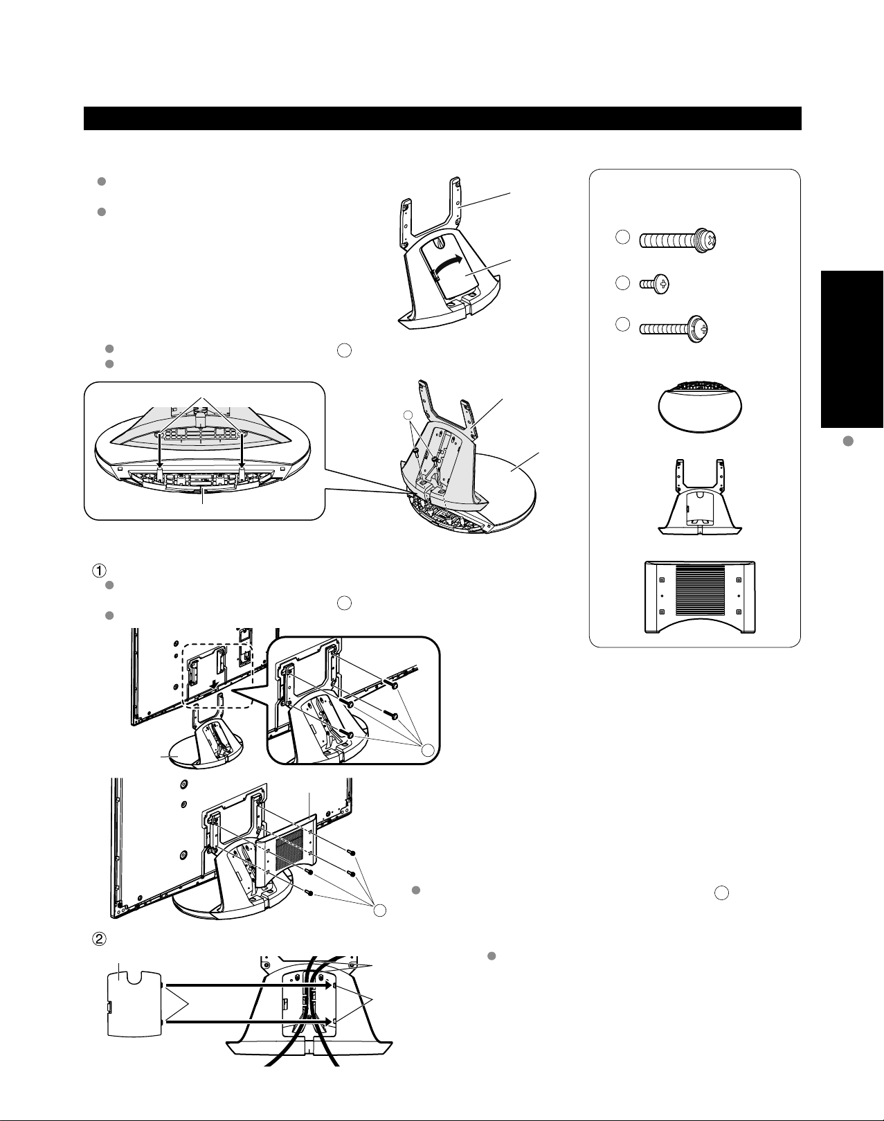
Assembling the pedestal
A
C
B
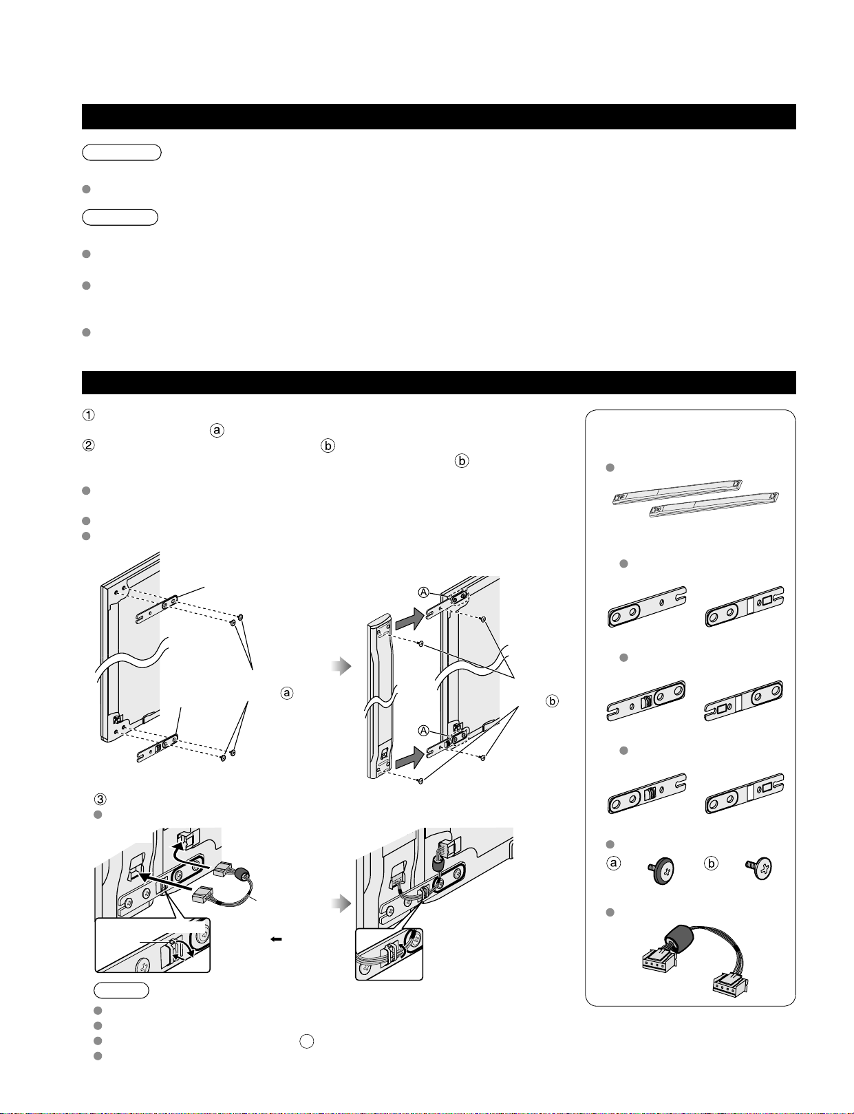
■
Attaching the pedestal to TV
Be careful not to scratch the surface (part with
gloss finish) of the base during assembly
Remove the cable cover attached to the
frame. (It will be used again after the pedestal
is attached to the display Unit.)
Fix securely with assembly screws A. (Total 2 screws)
Tighten screws firmly (tightening torque: 1.8 - 2.0 N• m)
Hole for the base installation
Base
Set-up
■
Frame
Cable cover
Frame
Attach the pedestal to TV
Slide the pedestal frame posts into the brackets on the back of the TV.
Fix securely with assembly screws C. (Total 4 screws)
Tighten screws firmly (tightening torque: 1.5 - 1.8 N• m)
Base
Accessories
Assembly screws
M8 × 30 (Silver) (2)
M4 × 10 (Black) (4)
M5 × 25 (Black) (4)
Base (1)
Frame (1)
Holder cover (1)
Accessories/Optional Accessory
Pedestal
Holder cover
Attach the Holder cover with assembly screws B.
(Total 4 screws)
Attach the cable cover
Cable cover
Tabs
Insert the tabs of the
cable cover into the hole at
the back of the pedestal.
Cable
Hole
Place each cable in the groove at the back of the
pedestal and snap the cable cover in.
* The lower part of the groove is separated in right
and left. Use the one suitable for you.
Page 10
10
11
Quick Start
Guide
Accessories
Speaker (2)
SP-54Z1U
Mounting bracket
[Top] (2)
TXFKR04DLUJ
Front Back
[Lower right] (1)
TXFKR05DLUJ
Front Back
[Lower left] (1)
TXFKR06DLUJ
Front Back
Assembly screws
TXFXY01DLUJB
(8) (8)
Speaker cable (2)
TXJ/SPDKUU-1
Accessories/Optional Accessory
(Continued)
Attaching the pedestal to TV (continued)
Attaching the pedestal to TV
Warning
Do not disassemble or modify the pedestal.
Otherwise the TV may fall over and become damaged, and personal injury may result.
Caution
Do not use any other TV and displays.
Otherwise the TV may fall over and become damaged, and personal injury may result.
Do not use the pedestal if it becomes warped or physically damaged.
If you use the pedestal when it is physically damaged, personal injury may result. Contact your nearest Panasonic
Dealer immediately.
During set-up, make sure that all screws are securely tightened.
If sufficient care is not taken to ensure screws are properly tightened during assembly, the pedestal will not be
strong enough to support the TV, and it might fall over and become damaged, and personal injury may result.
Attaching the Speaker to TV
Fix the Mounting bracket securely to the back of the Display unit with
Assembly screws .
Insert the speaker mounting screws temporarily in the screw outermost
holes of the speaker and fix the speaker mounting screws to the speaker
mounting bracket.
Orient the front side of the Mounting bracket toward the rear side of the
speaker and Display Unit side.
Fix it same as the speaker at the other side.
There will be a gap between the Display Unit and the speaker.
Mounting
bracket
[Lower right]
Assembly
screws
Back of
Display Unit
Mounting bracket
[Top]
Assembly
screws
Back of
Display Unit
Speaker
Place the temporarily inserted screws
into the counter sunk holes
on the bracket
Connect Display Unit and speaker with speaker cable.
Fix it in the same way as the speaker on the other side.
Lower right
(Back of Display Unit)
Speaker
cable
Speaker
Press the
part and
remove the hook.
Hook
To open the Clamper
Connect the terminal
near the ferrite core to
the Display Unit.
Note
Tighten the screws firmly.
Insert to the end of the speaker cable terminal firmly.
Loosen the screw shown in fig. A above to adjust the gap between the speaker and the Display Unit.
Do not hold the speaker to transport the unit.
HDMI AV OUT
Page 11
11
Quick Start
Guide
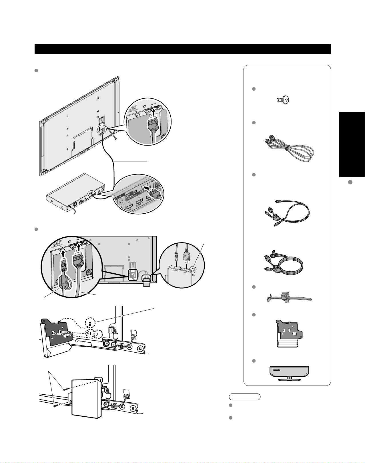
Connecting Display Unit, Tuner Box and Wireless Unit
HDMI AV OUT
Wired connection
■
Connect Display Unit to Tuner Box
Display Unit
Tuner
Box
HDMI Cable
Accessories
Assembly screws (2)
TXFXY01JSUJB
M4 × 10
HDMI cable
K1HY19YY0006
9.8 ft (3.0 m)
Exclusive cable for Wireless Unit
TXFMM01JSUU
Exclusive cable for Wireless
Receiver
1.6 ft (0.5 m)
Accessories/Optional Accessory
Wireless connection
■
Connect Wireless Unit (Receiver) to Display Unit
Exclusive cable for Wireless Receiver
ferrite core
Assembly screws
Hole for Cable
clamper
Insert the metal tab on the
top of the Wireless Unit
(Receiver) into the groove of
the Display Unit.
Insert the tabs on the front of
the Wireless Unit (Receiver)
into the holes at the back of
the Display Unit.
Exclusive cable for Wireless
Transmitter
3.3 ft (1.0 m)
Cable clamper (2)
TMME364
Wireless Unit (Receiver)
TU-WHR1U
Wireless Unit (Transmitter)
TU-WHT1U
Fix securely with assembly
screws (Total 2 screws).
Caution
Do not disassemble or modify the
Wireless Unit.
Connect the Exclusive cable for
Wireless Receiver which has
ferrite core on Display Unit side.
Page 12
12
13
Quick Start
Guide
Accessories/Optional Accessory
(Continued)
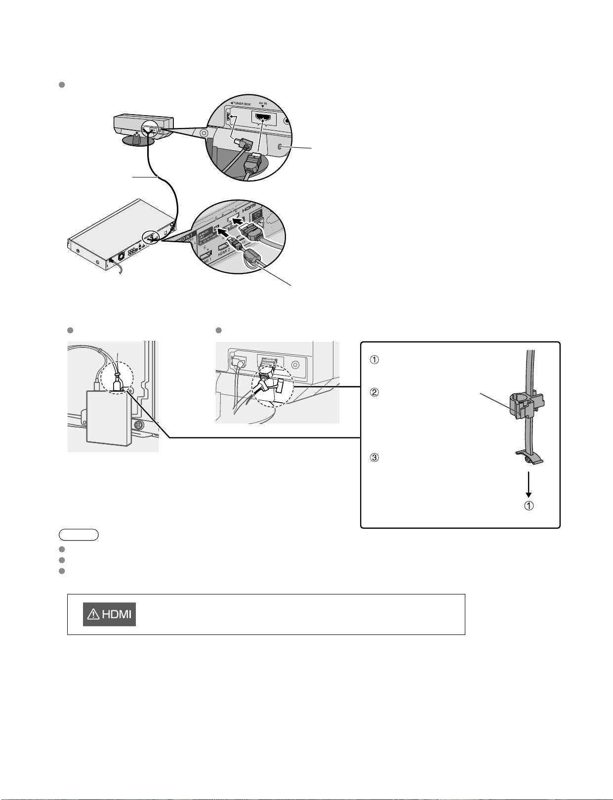
Note
Do not connect any other device than Wireless Unit to the HDMI terminal of the Display Unit/Tuner Box.
Connect the Exclusive cable for Wireless Transmitter which has ferrite core to Tuner Box side.
If the connection is not correct, the following icons will be displayed when the Display unit and the Tuner box are
turned on.
Connect Wireless Unit (Transmitter) to Tuner Box
Exclusive cable
for Wireless
Transmitter
Hole for Cable
clamper
ferrite core
■
Cable Binding for Wireless Unit
Wireless Unit (Receiver) Wireless Unit (Transmitter)
Attach to hole for Cable
clamper
Unlock it and connect
the AV cable out of
the Exclusive cable
for Wireless Receiver/
Transmitter.
Fix the cable so that it will
not become unplugged.
This Display Unit is connected to a device other than Tuner Box.
Page 13
13
Quick Start
Guide
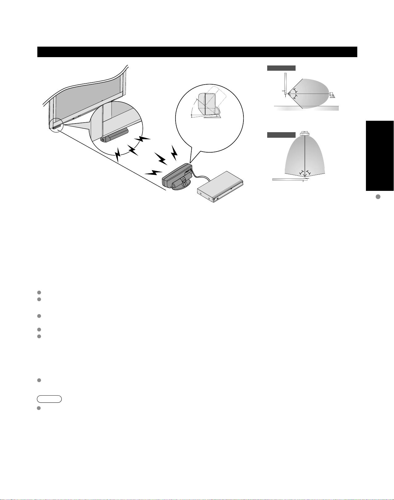
Installing the Display Unit, Tuner Box and Wireless Unit
Side View
approx. 10 m
40°
5
°
The angle of the
transmitter can be adjusted
to 40º upward and 5º
downward.
5 m
Display
Receiver
Floor
Top View
5 m
[Horizontal Direction]
45°
45°
5 m
[Vertical Direction]
Display
Transmitter
10 m
80°80°
Receiver
Transmitter
5 m
Precautions for Wireless Unit
Transmission Range
Use the Wireless Unit (Transmitter) within a straight line distance of 10 m (approx.) from the Wireless Unit (Receiver).
The range may be shortened if there are any obstacles or the surrounding environment or building structure affects
the transmission.
Installation Environment
Do not install this apparatus in the following locations to avoid distortion of image or audio or unit failure due to the
radio performance degradation.
Location subject to be high temperature (near the heater etc.)
Location with poor air circulation (at the end of a closed rack etc.)
In the following cases, the image or audio may be distorted or intermittent, or the apparatus may not operate properly
There is a strong obstacle for the radio waves between the Wireless Unit (Transmitter) and Wireless Unit (Receiver).
(furniture, AV devices, rack, rack door etc.)
Wireless Unit (Transmitter) is not facing the Wireless Unit (Receiver).
Wireless Unit (Transmitter) is placed significantly far from the front of Wireless Unit (Receiver) direction.
(Especially in a high position near the TV display, behind the TV, behind the right side of the pedestal)
Interference from Other Devices
If the Wireless Unit (Transmitter)/Wireless Unit (Receiver) is too close to other devices, failures such as malfunction
or slow remote control response may occur due to the radio wave interference.
Keep the transmitter away from the following devices as much as possible:
Wireless LAN, Microwaves, Telephones, Other electric devices
Accessories/Optional Accessory
:
Note
When the signal state is poor and the power lamp of the Wireless Unit (Transmitter) / Wireless Unit (Receiver) is lit
red, communication may not be able to be performed again automatically (no video and audio output).
In such a case, turn the power off and then on again with the remote control.
Page 14
14
15
Quick Start
Guide
To connect the antenna terminal and Cable Box
Accessories/Optional Accessory
(Continued)
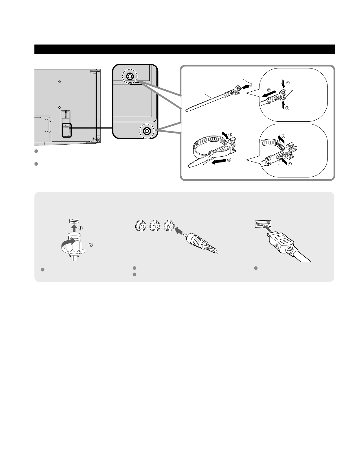
Cable Binding Instructions
Antenna terminal Pin terminals HDMI terminal
greenbluered
green
Firmly tighten by hand.
Match colors of plugs and terminals.
Insert firmly.
Insert firmly.
Reference of connection
To attach
hole
Insert
To bundle
To remove
To loosen
Keep pushing
both sides until
they snap
Snaps
Set
hooks
knob
Keep pushing
the knob
Cable clamper
Fasten the cables with the Cable clamper as
necessary.
When using the options, follow the option’s
assembly manual to fix cables.
Page 15
15
Quick Start
Guide
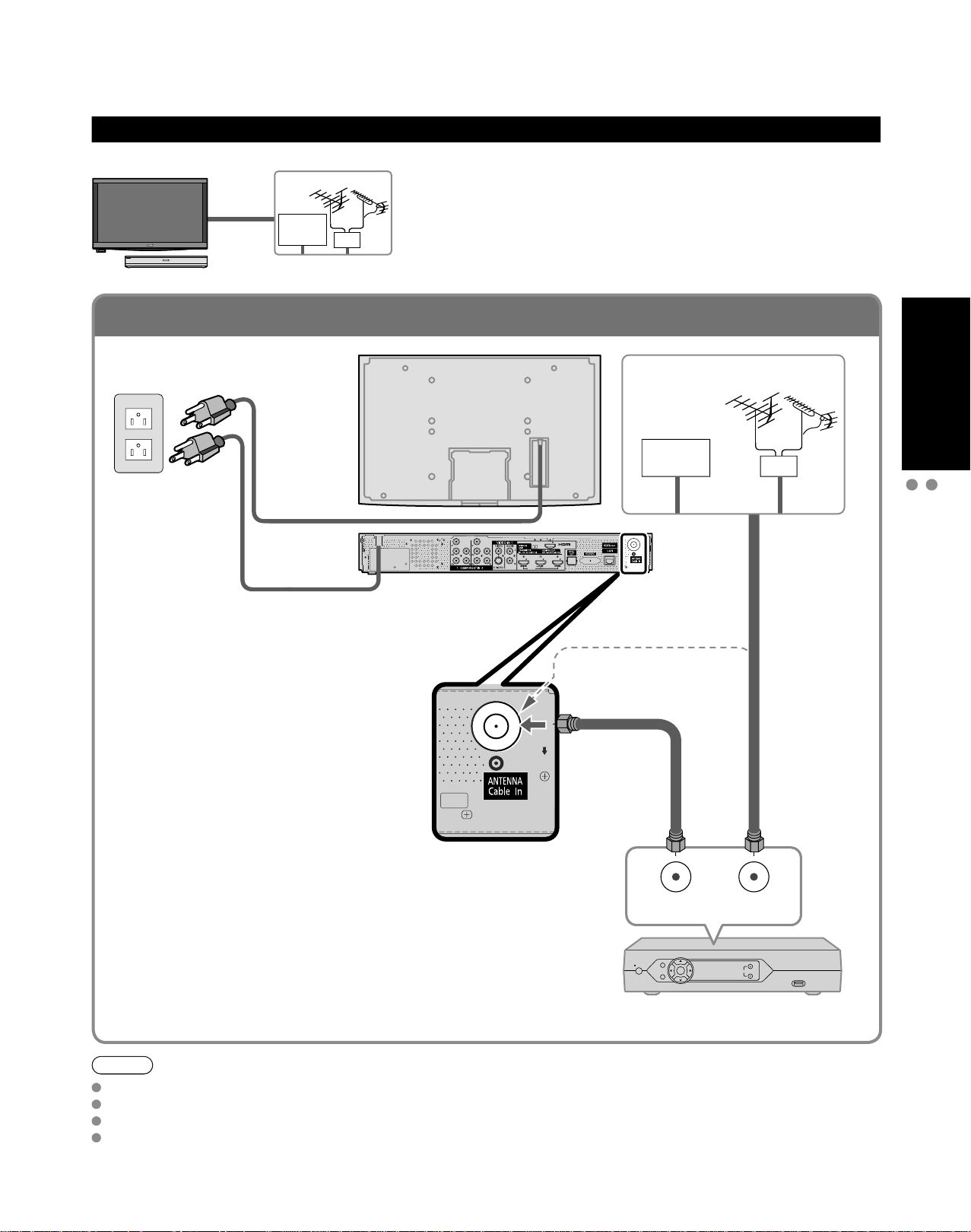
To connect the antenna terminal and Cable Box
Basic Connection
Example 1
TV
AC 120 V
60 Hz
AC Cord
(Connect after
all the other
connections have
been made.)
Connecting Antenna (To watch TV)
VHF/UHF Antenna
Cable TV
VHF/UHF Antenna
NTSC (National Television System Committee):
•
Conventional broadcasting
ATSC (Advanced Television Systems Committee):
•
Digital TV Standards include digital high-definition television
(HDTV), standard-definition television (SDTV), data broadcasting,
multi-channel surround-sound audio and interactive television.
AV IN
Cable TV
VHF/UHF Antenna
or
Basic Connection (Antenna + TV)
Accessories/Optional Accessory
(If no Cable Box)
or
Cable Box/Cable
You need to subscribe to a cable TV service to enjoy viewing their
•
programming.
If using a Cable Box set the TV channel to CH3 or CH4 for regular cable.
•
You can enjoy high-definition programming by subscribing to a high-
•
definition cable Service.
The connection for high-definition can be done with the use of HDMI or
Component Video cable. (p. 18)
To view high-definition programming select the correct video input. (p. 32)
•
Note
Not all cables and external equipment shown in this book are supplied with the TV.
For more details on the external equipment’s connections, please refer to the operating manuals for the equipment.
When disconnecting the power cord, be absolutely sure to disconnect the power cord plug from the wall outlet first.
For additional assistance, visit us at: www.panasonic.com
www.panasonic.ca
ANT OUT ANT IN
Cable Box
Page 16
16
17
Quick Start
Guide
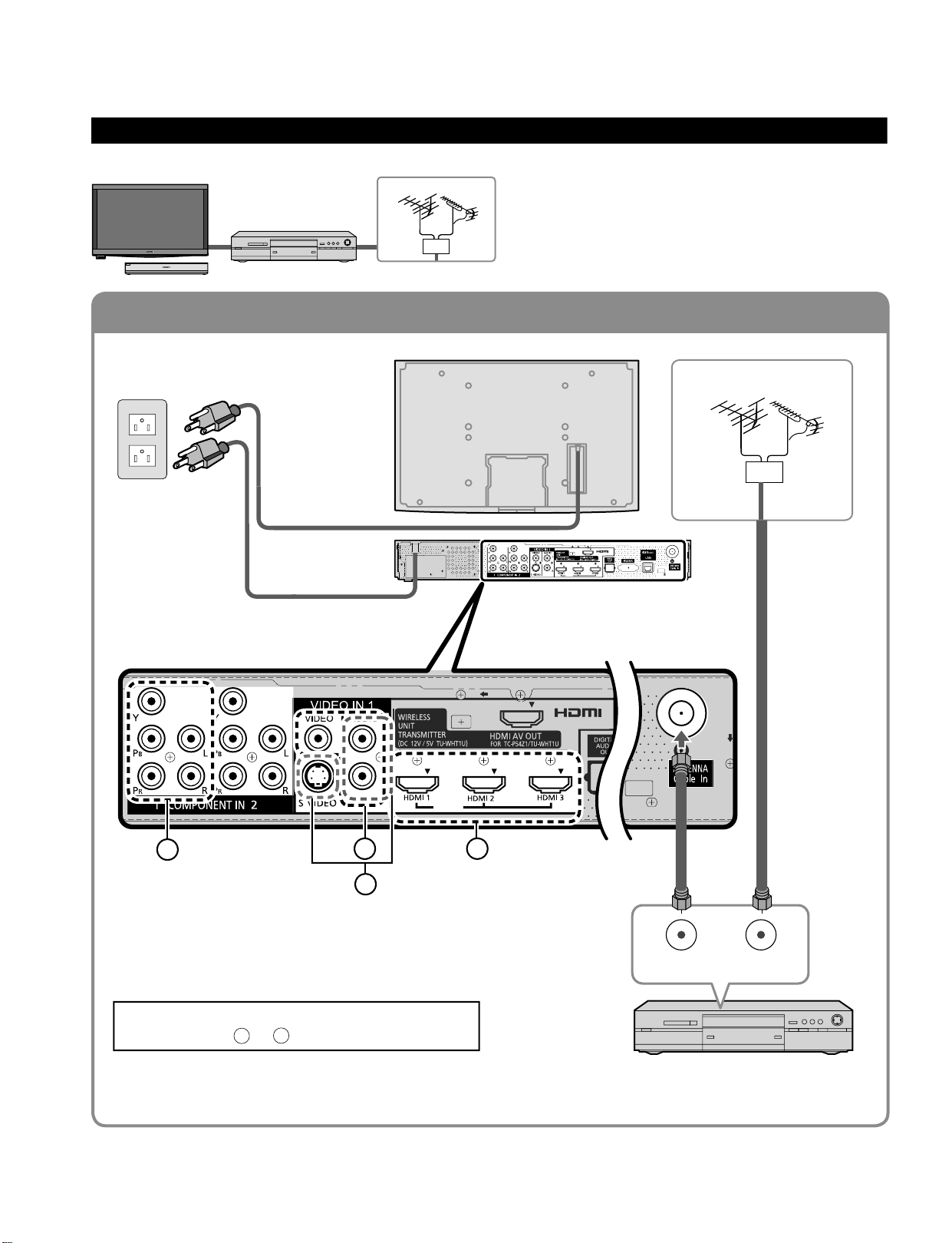
To connect the antenna terminal and DVD recorder or VCR
To connect the antenna terminal and Satellite Receiver and DVD recorder or VCR
AV IN
AV IN
Basic Connection (Continued)
Example 2
Connecting DVD recorder (VCR) (To record/playback)
DVD Recorder
If the source has a higher resolution signal (480p/720p/
1080i/1080p), connection can be made with the use of
a Component Video or HDMI cable. (p. 18)
VCR
Connection can be made with the use of an RF cable
and Composite Video/S Video cable. (p. 18)
VHF/UHF Antenna
TV
AV Equipment
(e.g. DVD Recorder
or VCR)
AC Cord
AC 120 V
60 Hz
VHF/UHF Antenna
AV Equipment
(e.g. DVD Recorder or VCR)
(with TV tuner)
Connecting TV and AV equipment
Please refer to
A
- D on p. 18
A
D
AV IN
B
D
A
C
ANT OUT ANT IN
Page 17
17
Quick Start
Guide
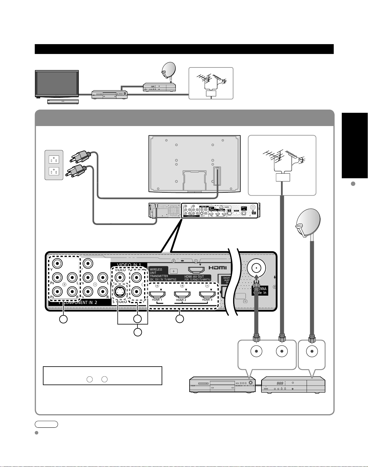
To connect the antenna terminal and Satellite Receiver and DVD recorder or VCR
AV IN
Example 3
Connecting DVD recorder (VCR) and satellite receiver
TV
DVD Recorder
or
VCR
Satellite
Receiver
VHF/UHF Antenna
You can enjoy high-definition
programming by subscribing to
high-definition satellite service.
Connection can be done with the
use of HDMI or Component Video
cable. (p. 18)
AC 120 V
60 Hz
VHF/UHF Antenna
AC Cord
AV IN
Basic Connection (TV + DVD Recorder or VCR + Satellite Receiver)
B
Connecting TV and AV equipment
Please refer toA - D on p. 18.
D
C
A
(with TV tuner)
ANT OUT ANT IN
Satellite ReceiverDVD Recorder or VCR
(TV + DVD Recorder or VCR)
ANT IN
Note
For details of external equipment connections, please refer to the operating manuals for the equipment.
Page 18
18
19
Quick Start
Guide
High-Definition
Standard-Definition
Note
Some programs contain a copyright protection signal to prevent recording.
When the copyright protection program is displayed, do not connect the other TV monitor through a VCR. Video signals fed
through VCRs may be affected by copyright protection systems and the picture will be distorted on the other TV monitor.
For more details on the external equipment’s connections, please refer to the operating manuals for the equipment.
AV IN
Basic Connection (Continued)
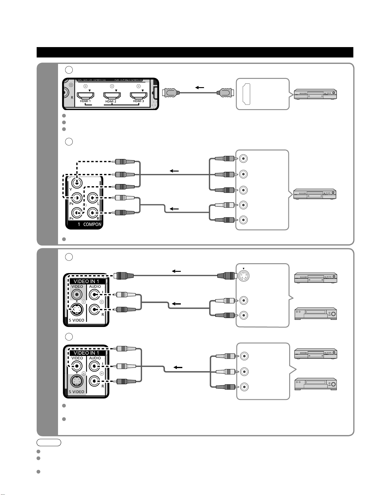
A
To use HDMI terminals
AV IN
HDMI
AV OUT
e.g. Blu-ray Disc player
AV Equipment
Connecting to HDMI terminals will enable you to enjoy high-definition digital images and high-quality sound.
The HDMI connection is required for a 1080p signal.
For “VIERA LinkTM connections”, please refer to p. 45.
B
To use COMPONENT terminals
L
R
Y
P
B
PR
COMPONENT
VIDEO OUT
AUDIO
OUT
white
red
green
blue
red
white
red
green
blue
red
white
red
green
blue
red
e.g. Blu-ray Disc
player
AV Equipment
Recorders may also be connected to COMPOSITE or S VIDEO terminals. (see below)
C
To use S VIDEO terminals
white
red
white
red
AUDIO
OUT
S VIDEO
OUT
white
red
or
e.g. DVD Recorder
AV Equipment
e.g. VCR
D
To use COMPOSITE terminals
COMPOSITE
OUT
yellow
white
red
yellow
white
red
yellow
white
red
or
e.g. DVD Recorder
AV Equipment
e.g. VCR
The S Video input will override the composite video signal when S Video cable is connected. Connect
either S Video or Video cable.
Connecting to S VIDEO terminals will enable you to enjoy greater picture quality than using Composite
terminals.
AV cable connections TV controls/indicators
L
R
L
R
Page 19
19
Quick Start
Guide
AV IN
Identifying Controls
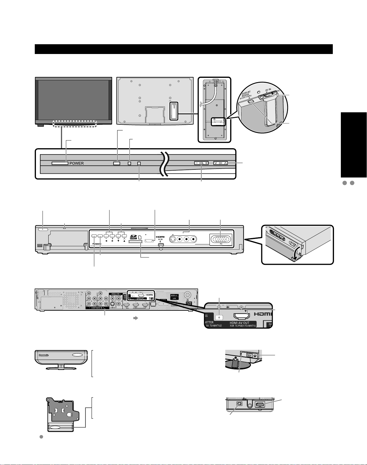
Display Unit
■
Front of Display Unit
Back of Display Unit
HDMI terminal
(For Tuner Box
or Wireless Unit
connection)
Power button
Tuner Box
■
Front of Tuner Box
Power button
Power indicator
(on: red, off: no light)
POWER
Changes the input mode
Chooses menu and submenu entries.
Back of Tuner Box
Power indicator
(On: red, Standby: orange, Off: no light)
Volume up/down
Selects channels
in sequence
VOL
INPUT/OK
MENU
Displays the
Main menu.
Remote control sensor
C.A.T.S. sensor. (Contrast
Automatic Tracking System).
HDMI 4 terminal
CH
SD card slot
VIDEO IN 2
terminals
VIDEO IN 2
S VIDEO
VIDEO
Volume up/down
L-AUDIO-R
Selects channels in
sequence
PC terminal
DC terminal
(For Wireless Unit connection)
DC terminal
(For Wireless
Unit connection)
Identifying Controls
Basic Connection (AV cable connections)
p. 62
Wireless Unit
■
Other terminals
Front of Wireless Unit (Transmitter)
Off: Power off
Red: Power on and no communication
Green: Power on and communication state good
Orange: Power on and communication state not good
Red (blinking): Indicates malfunction
Front of Wireless Unit (Receiver)
Off: Power off
Red: Power on and no communication
Green: Power on and communication state good
Red (blinking): Indicates malfunction
When the red LED is blinking, turn the power of the Tuner Box and
Display Unit off and then on again. If the problem is not resolved,
consult your local Panasonic dealer.
HDMI AV OUT terminal
(For Display Unit
or Wireless Unit
connection)
Back of Wireless Unit (Transmitter)
AV terminal
(For Tuner Box
connection)
DC terminal
(For Tuner Box connection)
Back of Wireless Unit (Receiver)
AV terminal
(For Display Unit
connection)
DC terminal
(For Display Unit connection)
Page 20
20
21
Quick Start
Guide
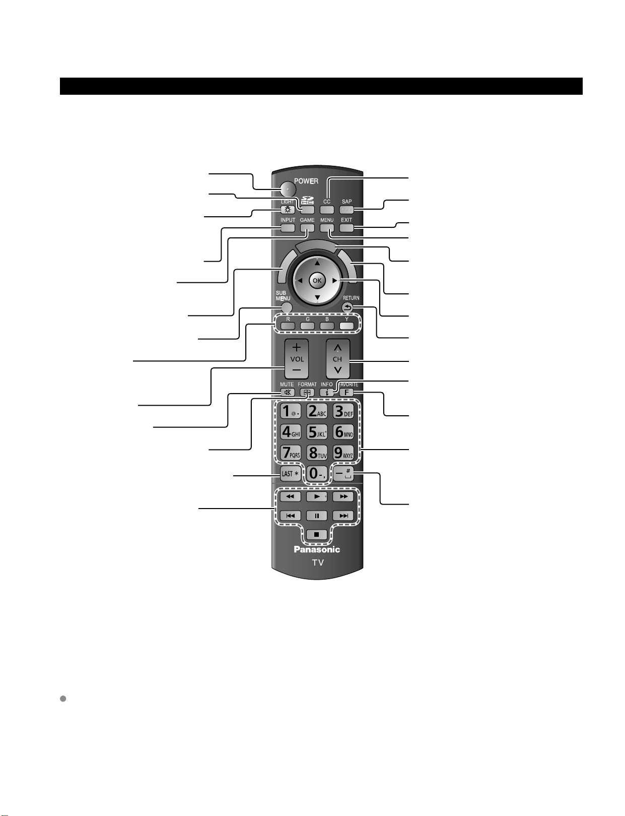
Remote control
Switches TV On or Off (Standby)
Viewing from SD Card (p. 28-31)
Lights the CH and VOL buttons
for 5 seconds. Press again to turn
off the CH and VOL button lights.
Changes the input mode (p. 32)
Switches to input terminal
that has “GAME” label. (p. 32)
VIERA Link menu (p. 48-49)
Displays Sub Menu (p. 25, 42)
Colored buttons
(used for various functions)
(for example, p. 24, 28, 48)
Volume up/down
Sound mute On/Off
Changes aspect ratio (p. 26, 64)
Switches to previously viewed channel
or input modes.
External equipment operations
(p. 49)
Closed caption On/Off (p. 25)
Selects Audio Mode for TV viewing (p. 25)
Exits from menu screen
Displays Main Menu (p. 40)
Displays VIERA CAST screen (Home
screen) (p. 34)
Displays VIERA TOOLS (p. 27)
Selects/OK/Change
Returns to previous menu
Channel up/down
Displays or removes the channel
banner (p. 26)
Operates the Favorite channel list
function. (p. 26)
Numeric keypad to select any channel
(p. 25) or press to enter alphanumeric
input in menus. (p. 24, 32, 36, 38, 48,
50, 52, 54, 56, 59, 60)
Use for digital channels. (p. 25)
Remote control registration
Press the ‘OK’ button and the ‘1’ button
simultaneously for at least 3 seconds.
Registro del mando a distancia
Presione el botón ‘OK’ y el botón ‘1’
simultáneamente, durante al menos 3 segundos.
Enregistrement de la télécommande
Appuyez simultanément sur les touches ‘OK’ et ‘1’
pendant au moins 3 secondes.
Remote control registration
completed successfully.
Press OK.
Registro del mando a distancia
completado satisfactoriamente.
Presione OK.
Enregistrement de la télécommande réussi.
Appuyez sur OK.
Identifying Controls (Continued)
This TV uses a RF remote control.
The remote control is operable when it is not facing the Display Unit or Tuner Box.
As the radio waves reflect on walls or other obstacles, the remote control is operable even there are obstacles
between the remote control and the Tuner Box.
Transmission Range
Use the RF remote control within the range of 7 m from the TV tuner.
The range may be shortened if there are any obstacles or the surrounding environment or building structure affects
the transmission.
Interference from Other Devices
If the TV tuner is too close to another device, failures such as malfunction or slow remote control response may occur
due to the radio wave interference.
Keep the transmitter away from the following devices as much as possible:
Wireless LAN, Microwaves, Telephones, Other electric devices
C
A
A
R
S
E
I
T
V
k
n
i
L
A
R
E
I
V
V
I
E
R
A
T
O
O
L
S
Page 21
21
Quick Start
Guide
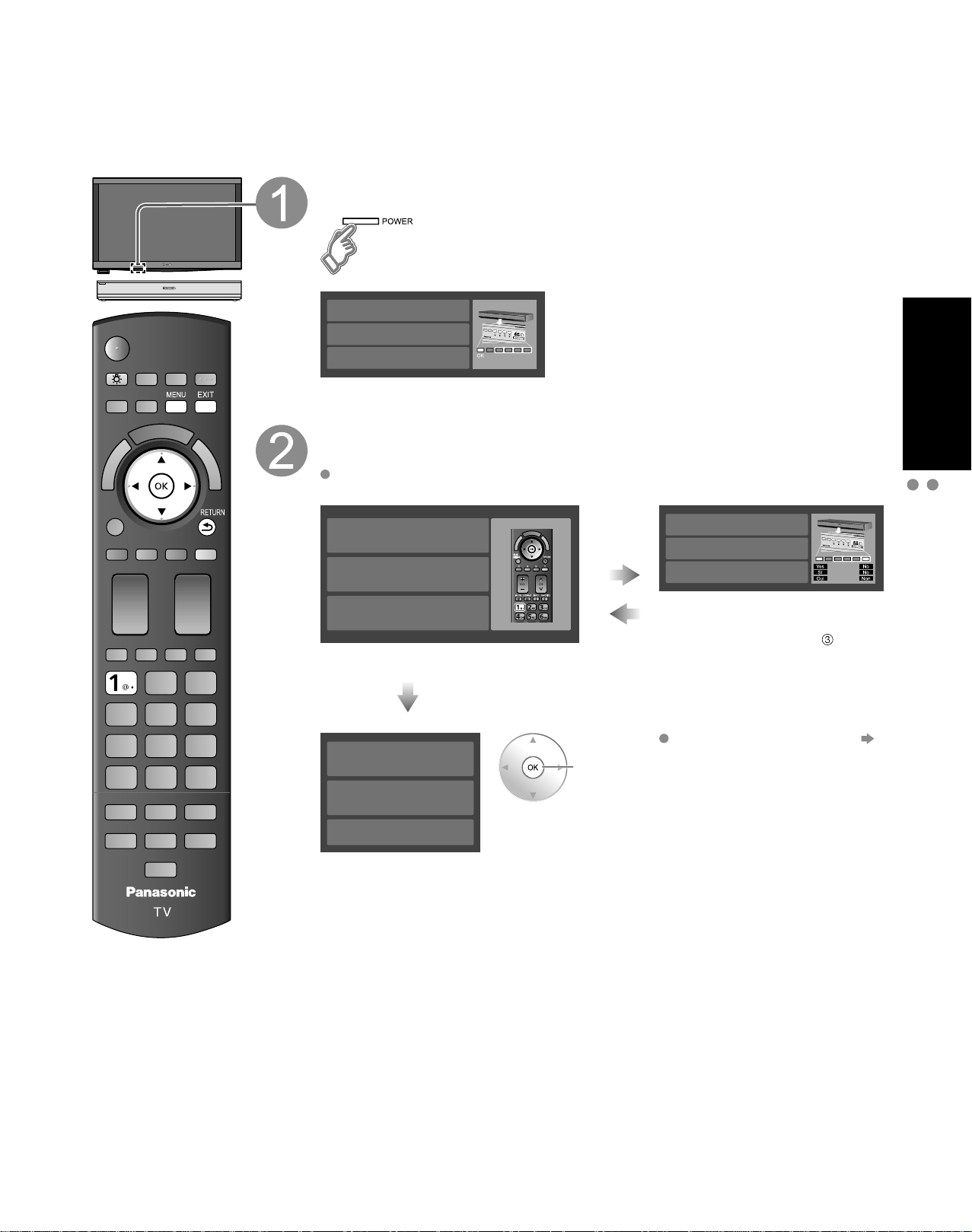
First Time Setup (Remote control registration)
Remote control registration
Press the ‘OK’ button and the ‘1’ button
simultaneously for at least 3 seconds.
Registro del mando a distancia
Presione el botón ‘OK’ y el botón ‘1’
simultáneamente, durante al menos 3 segundos.
Enregistrement de la télécommande
Appuyez simultanément sur les touches ‘OK’ et ‘1’
pendant au moins 3 secondes.
Remote control registration
completed successfully.
Press OK.
Registro del mando a distancia
completado satisfactoriamente.
Presione OK.
Enregistrement de la télécommande réussi.
Appuyez sur OK.
Make sure to register your remote control with the following procedure when the TV is turned on for the
first time.
Turn the TV On with the POWER button (Display Unit)
(The Tuner Box power will be also turned on).
(Display Unit)
Please have your remote control ready
with batteries installed. Continue?
Por favor tenga su mando a distancia listo
con las baterías instaladas. Continuar?
Veuillez installer les piles dans
la télécommande. Continuer ?
INPUT/OK
MENU
CHVOL
Confirmation screen will be displayed.
Press the ‘OK’ button and the ‘1’ button simultaneously
for at least 3 seconds.
If there is no registered remote control, the “Remote control registration” screen
is displayed every time the TV is turned on.
Succeed
Error or
C
A
A
R
S
E
I
T
V
V
I
E
k
n
R
i
A
L
T
A
O
R
O
E
L
I
S
V
Time out
(30 sec)
Select
“Yes”
ok
Remote control registration failed.
Try registering again?
Registro fallido.
Intentar nuevamente?
Enregistrement de la télécommande échoué.
Enregistrer de nouveau ?
INPUT/OK
MENU
VOL
CH
You can also go to step
selecting “No”.
(Use control panel of Tuner Box,
when Remote control is not
available)
Remote control registration
(p. 61)
First Time Setup
Identifying Controls
Page 22
22
23
Quick Start
Guide
First Time Setup (Continued)
“First time setup” is displayed only when the TV is turned on for the first time after the power cord is
inserted into a wall outlet and when “Auto power on” (p. 42-43) is set to “No”.
■
Press to exit from
a menu screen
■
Press to return
to the previous
screen
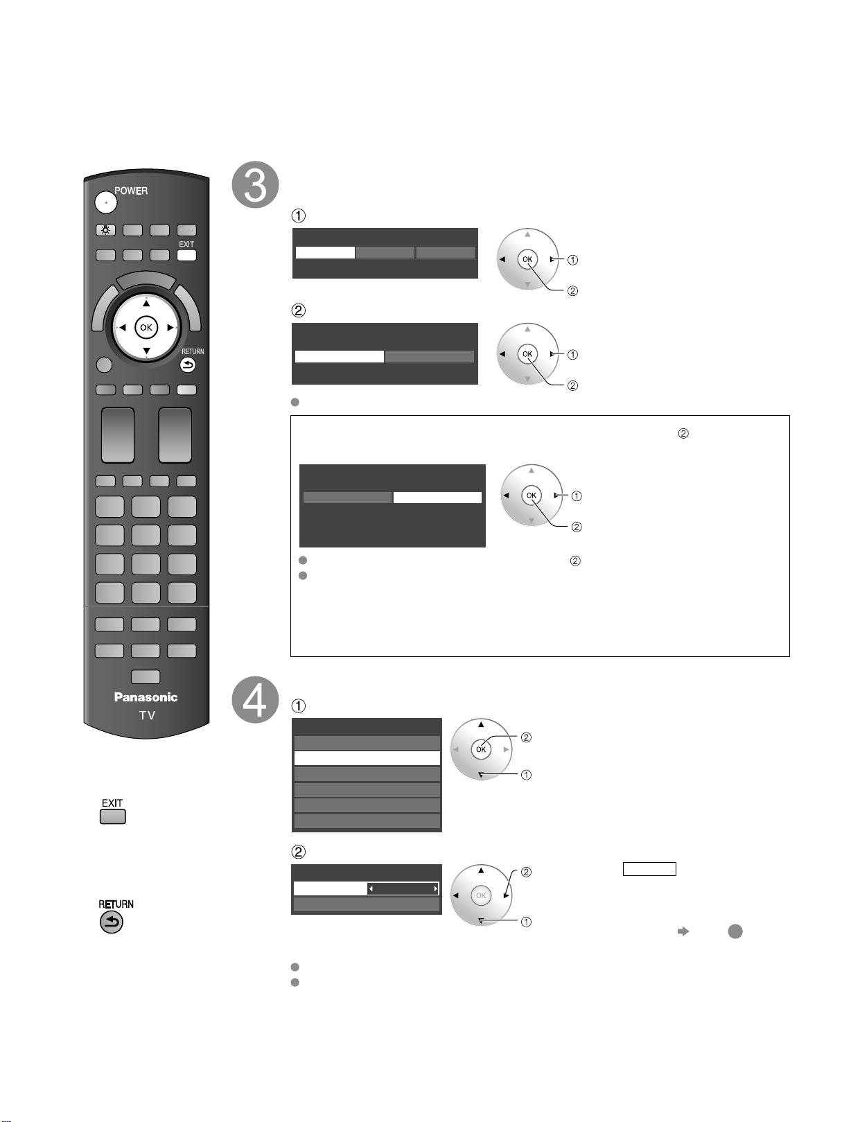
Select your viewing environment
* This setting will be skipped next time if you select “Home Use”.
Select your language
Language
English FrançaisEspañol
select
ok
Be sure to select “Home Use”
Please select your viewing environment
Select “Home Use” when using this TV in your home.
Home Use Store Demonstration
select
ok
Please confirm your selection (Home Use) before pressing OK button.
■
If you select “Store Demonstration” by mistake in ,
confirmation screen will be displayed.
You are selecting the mode for store demonstration
Yes No
If you select “Yes”, the picture mode will regularly reset
to “Vivid” and a Picture Refresh message will be
displayed on the screen.
select
ok
Select “No” and return to previous screen .
If you select “Yes”, Screen enters store demonstration mode.
To display the “Please select your viewing environment” screen again as
shown above and select “Home Use”, do one of the following:
• Press and hold down the front POWER button.
• Unplug the TV and plug it again.
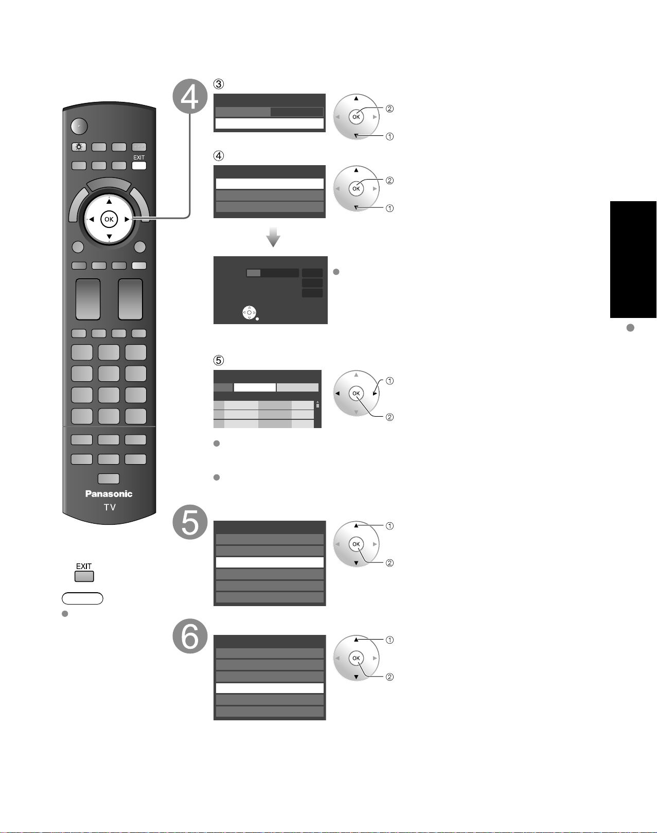
Auto channel setup
Select “ANT/Cable setup”
First time setup
Language
VIERA CAST setting
Network setting
Clock
ANT/Cable setup
Input labels
next
select
Select “ANT in”
Cable
ANT/Cable setup
ANT in
Auto program
set
select
ANT in
Cable: Cable TV
Antenna
: Antenna
Not used
: Skip TV tuning
go to
5
Select “Not used” when no wire is connected to the “Antenna/Cable” terminal.
Typical when Cable/Satellite box is connected to a TV input.
Prevents accidental tuning to an unavailable signal.
Cable
ANT/Cable setup
ANT in
Auto program
Auto program
All channels
Analog only
Digital only
Auto program
Progress
Number of analog channels
Number of digital channels
8%
10
0
Press RETURN to quit.
RETURN
program
CancelApply
Caption Favorite Add
...
...
Yes
...
...
Yes
...
...
Yes
First time setup
Language
VIERA CAST setting
Network setting
Clock
ANT/Cable setup
Input labels
First time setup
Language
VIERA CAST setting
Network setting
Clock
ANT/Cable setup
Input labels
Page 23
23
Quick Start
Guide
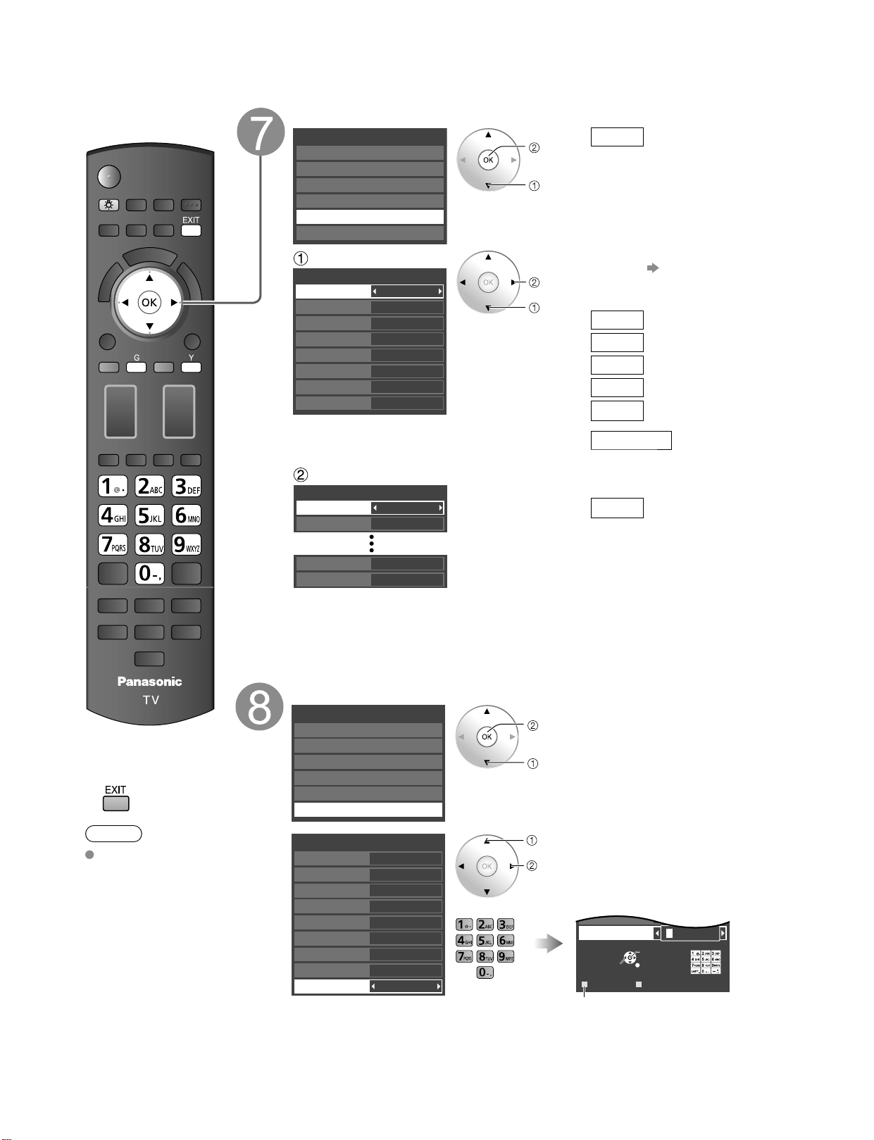
Select “Auto program”
Cable
ANT/Cable setup
ANT in
Auto program
Auto program
All channels
Analog only
Digital only
Auto program
Progress
Number of analog channels
Number of digital channels
8%
10
0
Press RETURN to quit.
RETURN
program
CancelApply
Caption Favorite Add
...
...
Yes
...
...
Yes
...
...
Yes
First time setup
Language
VIERA CAST setting
Network setting
Clock
ANT/Cable setup
Input labels
First time setup
Language
VIERA CAST setting
Network setting
Clock
ANT/Cable setup
Input labels
next
select
Select scanning mode (ALL channels/Analog only/Digital only)
ok
select
Start scanning the channels
Available channels (analog/digital) are automatically set.
All channels: Scans digital and analog channels
Analog only: Scans Analog channels only
Digital only: Scans Digital channels only
Confirm registered channels
select “Apply”
ok
If OK is not pressed after selecting “Apply”, the channels will not be saved.
The channel will be saved when no operation is performed for 60 seconds and
the “Manual program” menu will also exit automatically.
If you perform scanning more than twice, previously saved channels are erased.
First Time Setup
Press to exit from
■
a menu screen
Note
To change setting
(Language/
ANT/Cable setup/
Network setting/
VIERA CAST setting/
Clock/Input labels)
later, go to Menu
screen
(p. 42)
Network setting
VIERA CAST setting
select
ok
Network setting (p. 50-51)
select
ok
VIERA CAST setting (p. 52-53)
Page 24
24
25
Quick Start
Guide
First Time Setup (Continued) Watching TV
CH
Listen
with SAP
(Secondary
Audio
Program)
■
Select Audio Mode for watching TV
Digital mode
Press SAP to select the next audio track (if available) when receiving a digital
channel.
Analog mode
Press SAP to select the desired audio mode.
• Each press of SAP will change the audio mode. (Stereo/SAP/Mono)
Closed
caption
■
Switches Closed caption mode On or Off
Closed caption On Closed caption Off
Display the
SUB MENU
■
Press SUB MENU to show sub menu screen. (p. 42)
This menu consists of shortcuts to convenient functions.
All
Setup SUB MENU
Edit CH caption
Signal meter
Set favorite
Channel surf mode
■
Press to exit from
a menu screen
Note
About broadcasting
systems
Analog (NTSC):
Conventional
broadcasting
Digital (ATSC):
New
programming
that allows
you to view
more channels
featuring
high-quality video
and sound
Adjust the clock
First time setup
Language
VIERA CAST setting
Network setting
Clock
ANT/Cable setup
Input labels
next
select
Mode
Manual: Adjust the clock manually
(Year/Month/Day/Hour/Minute)
Auto:
The clock is adjusted
automatically via Internet
service.
Only available when the TV
is on a network.
Set “Network setting” and
“VIERA CAST setting” first.
(Time zone/DST)
Manual setting
Manual
2009
1
7
10 AM
10
NST
Off
Clock
Mode
Year
Month
Day
Hour
Minute
Time zone
DST
set
select
item
Year
Select the year
Month
Select the month
Day
Select the day
Hour
Adjust the hour
Minute
Adjust the minute
Time zone
Select your time zone.
(EST/CST/MST/PST/AKST/
HST/NST/AST)
Auto setting
Auto
2009
2009/ 6/11 8:07AM
Clock
Mode
Year
Est
On
Timezone
DST
DST
Set DST (Daylight Saving
Time) setting. (On/Off)
On:
Advances the clock one
hour from the time is set
according to the time zone.
Set the Input labels
First time setup
Language
VIERA CAST setting
Network setting
Clock
ANT/Cable setup
Input labels
next
select
GAME
GAME
Input labels
Component 1
Component 2
HDMI 1
HDMI 2
HDMI 3
HDMI 4
Video 1
Video 2
PC
select
set
or
GAME
Select
OK
RETURN
DeleteABC → abc
G Y
Video 2
PC
G A A
Switches Input mode alphabet to
numeric
Label: [BLANK] SKIP/VCR/DVD/CABLE/SATELLITE/DVR/GAME/AUX/RECEIVER/
COMPUTER/Blu-ray/CAMERA/DVD REC/HOME THTR/MONITOR/MEDIA
CTR/MEDIA EXT/OTHER
Page 25

25
Quick Start
Guide
Connect the TV to a cable box/cable, set-top-box, satellite box or antenna cable (p. 15-18)
CH
Listen
with SAP
(Secondary
Audio
Program)
■
Select Audio Mode for watching TV
Digital mode
Press SAP to select the next audio track (if available) when receiving a digital
channel.
Analog mode
Press SAP to select the desired audio mode.
• Each press of SAP will change the audio mode. (Stereo/SAP/Mono)
Closed
caption
■
Switches Closed caption mode On or Off
Closed caption On Closed caption Off
Display the
SUB MENU
■
Press SUB MENU to show sub menu screen. (p. 42)
This menu consists of shortcuts to convenient functions.
All
Setup SUB MENU
Edit CH caption
Signal meter
Set favorite
Channel surf mode
To watch TV and other functions
Turn power on
Note
or
If the mode is not TV, press and
select TV. (p. 32)
(Tuner Box)
Select a channel number
or
(Diaplay Unit)
To directly input the digital channel number
■
When tuning to a digital channel, press the button to enter the
minor number in a compound channel number.
example: CH15-1:
Note
Reselect “Cable” or “Antenna” in “ANT in” of “ANT/Cable setup” to switch the
signal reception between cable TV and antenna. (p. 22, 57)
The channel number and volume level remain the same even after the TV is
turned off.
(Tuner Box)
Viewing
Watching TV
First Time Setup
Audio track 1 of 2
(English)
SUB
MENU
Page 26

26
27
Viewing
■
Other Useful Functions (Operate after )
Information
Recall
■
Displays or removes the channel banner.
Channel
Station
identifier
SAP
indication
Signal
resolution
Rating Level
Picture
mode
Sleep timer
remaining time
Aspect ratio
Closed caption
Clock
Change
aspect
ratio
■
Press FORMAT to cycle through the aspect modes. (p. 64)
• 480i, 480p: FULL/JUST/4:3/ZOOM
• 1080p, 1080i, 720p: FULL/H-FILL/JUST/4:3/ZOOM
Call up
a favorite
channel
■
FAVORITE
Channel numbers registered in Favorite are displayed on the favorite tune
screen. Select the desired broadcast station with the cursor or use number
buttons. (see below)
■
Set Favorite Feature
1
Display the SUB MENU.
2
Select “Set favorite”
All
Setup SUB MENU
Edit CH caption
Signal meter
Set favorite
Channel surf mode
select
ok
3
Set the displayed channel
Set favorite 1/3
26-1
1
2
3
4
5
select the list
number
save the displayed
channel
select the list number
(to save the channel
without pressing OK)
or
Delete a favorite channel
Set favorite 1/3
26-1
1
2
3
4
5
select
delete
(while holding down)
Favorite Feature
■
Use Favorite Feature
1
Display “Favorite channels”
2
Select the channel
Favorite channels
1/3
26-1
1
2
3
4
5
select
or
3
Set Favorite channel
Favorite channels
1/3
26-1
1
2
3
4
5
ok
■
To change the page
Press repeatedly to change between
pages(1/3, 2/3, 3/3 or exit)
Changes the page forward/backward
Watching TV (Continued)
SUB
MENU
15-2 12:30 PM
ABC-HD
THE NEWS
CC SAP
TV-G 1080i Standard 4:3
30
Page 27

27
Viewing
Using VIERA TOOLS
VIERA TOOLS is the easy way to access high use menu items. They are displayed as shortcut icons on
the TV screen.
Unlike a conventional menu, you can enjoy using, playing or setting a function quickly.
Display VIERA TOOLS
V
I
E
R
A
T
O
O
L
S
Select the item
select
next
Displayed “THX setting” menu. (P. 66)
Select Picture mode setting.
(THX/Standard (Vivid/Stadio ref/Game/Custom))
Press to exit from
■
a menu screen
Press to return
■
to the previous
screen
Start “VIERA CAST”. (p. 34-35)
Displayed “VIERA Link control” menu.
Select the equipment you want to access.
VIERA Link control only with the TV’s remote control
(p. 48-49)
Start Network Camera viewing (p. 36-37)
Displayed “SD card” menu.
Select SD card function.
(Slideshow/Thumbnail/Movie)
Viewing from an SD card (p. 28-31)
Displayed “ECO/energy saving” menu. (p. 42)
Using VIERA TOOLS
Watching TV
Page 28

28
29
Viewing
Viewing from an SD Card
You can view movies and photos taken with a digital camera or digital video camera and saved on an SD
card. (Media other than SD Cards may not be reproduced properly.)
■
Press to exit from
a menu screen
■
Press to return
to the previous
screen
Insert the SD card
* This setting will be skipped next time unless you select “Set later”.
Set “SD card setting” and select “Play SD card now”
“SD card setting” will be displayed automatically each time an SD card is
inserted for the first time.
Set later
SD card setting
Play SD card automatically
Play SD card now
select
change
set
Slideshow:
A Slideshow will start
automatically next time.
Thumbnail:
The Photo viewer menu will be
displayed automatically next time.
Movie: The video data plays
automatically from next time.
Set later: “SD card setting” menu will be
displayed repeatedly.
Off: The data can be played manually.
■
Manual operation (“Play SD card automatically” is “Off”)
Display “SD card”
Using VIERA TOOLS (p. 27)
or
Menu
Picture
Audio
VIERA Link
SD card
Closed caption
Setup
Select the item
SD card
Photo viewer
Movie player
select
ok
Photo viewer
Go to p. 30
Select the movie to be listed
Recording format (MPEG2/AVCHD)
Movie information
Date and time:
Date and time of
recording are displayed.
Duration:
Recording time is
displayed.
select
ok
View
Skip Skip
R YG B
Stop
RETURN
Play
Date and time
Duration
06/10/2009 11:34
00h05m27s
PLAY
00:00.14
Pause
Date and time
Duration
06/10/2009 11:34
00h05m27s
PLAY
00:00.14
•
To display/hide banner
Navigation area
Elapsed time of current movie
Movie Banner
•
To display Navigation area
•
To hide Navigation area
•
To previous movie
•
To next movie
Movie player
SD Card
Insert the card Remove the card
Label surface
Push until a click is
heard
Blue LED
Press in lightly
on SD Card, then
release.
Compliant card type (maximum capacity): SDHC Card (16 GB), SD Card (2 GB), miniSD Card
(1 GB) (requiring miniSD Card adapter)
For cautions and details on SD Cards (p. 65)
Blue LED lights while SD Card in inserted if set “SD card LED” to “On” in Setup Menu (p. 42)
Movie
settings
In or
■
Adjust the picture and Audio
Display “Movie settings”
example: Picture menu
Picture menu/Audio menu
(p. 40)
0
0
0
0
0
Vivid
Picture 1/3
Brightness
Color
Tint
Sharpness
Picture mode
Contrast
Reset to defaults
Select
Adjust
Select the item
On
Movie settings
Picture
Audio
VIERA Link
Repeat
select
ok
Set
■
Use VIERA Link function
■
Set up Repeat playback
VIERA Link (p. 40, 48)
Recorder
TV
VIERA Link control
Speaker output
Record now
Stop recording
Select
change
On
Movie settings
Picture
Audio
VIERA Link
Repeat
Select
change
Repeat
Turn the Movie play Repeat
function On or Off.
Change
Audio
current
status
In
Display “current audio
status”
Each press of SAP will change the audio mode.
(If the movie has multiple audio signals.)
(Current audio status)
It may take several seconds to change the sound.
POWER
CH
INPUT/OK
MENU
VOL
S VIDEO
VIDEO
VIDEO IN 2
L-AUDIO-R
V
I
E
R
A
T
O
O
L
S
Movie player
Select OK
RETURN
No. Date and time Duration
12/20/2008
10:26
1
01/17/2009
14:25
2
03/07/2009
07:25
3
04/24/2009
09:25
4
06/10/2009
11:34
5
08/19/2009
10:25
6
10/02/2009
12:25
7
10/13/2009
14:25
8
12/01/2009
16:25
9
00h16m35s
01h45m35s
00h05m35s
01h10m35s
00h05m27s
00h35m35s
00h12m35s
00h53m35s
01h24m35s
R YG B
Skip Skip
Pause
Play
RETURN
Stop
Page 29

29
Viewing
SD Card
Insert the card Remove the card
Label surface
Push until a click is
heard
Blue LED
Press in lightly
on SD Card, then
release.
Compliant card type (maximum capacity): SDHC Card (16 GB), SD Card (2 GB), miniSD Card
(1 GB) (requiring miniSD Card adapter)
For cautions and details on SD Cards (p. 65)
Blue LED lights while SD Card in inserted if set “SD card LED” to “On” in Setup Menu (p. 42)
Movie
settings
In or
■
Adjust the picture and Audio
Display “Movie settings”
example: Picture menu
Picture menu/Audio menu
(p. 40)
0
0
0
0
0
Vivid
Picture 1/3
Brightness
Color
Tint
Sharpness
Picture mode
Contrast
Reset to defaults
Select
Adjust
Select the item
On
Movie settings
Picture
Audio
VIERA Link
Repeat
select
ok
Set
■
Use VIERA Link function
■
Set up Repeat playback
VIERA Link (p. 40, 48)
Recorder
TV
VIERA Link control
Speaker output
Record now
Stop recording
Select
change
On
Movie settings
Picture
Audio
VIERA Link
Repeat
Select
change
Repeat
Turn the Movie play Repeat
function On or Off.
Change
Audio
current
status
In
Display “current audio
status”
Each press of SAP will change the audio mode.
(If the movie has multiple audio signals.)
(Current audio status)
It may take several seconds to change the sound.
Viewing from SD Card
This product is licensed under the AVC patent portfolio license for the personal and non-commercial use of a consumer to
(i) encode video in compliance with the AVC Standard (“AVC Video”) and/or (ii) decode AVC Video that was encoded by a
consumer engaged in a personal and non-commercial activity and/or was obtained from a video provider licensed to provide
AVC Video. No license is granted or shall be implied for any other use. Additional information may be obtained from MPEG LA,
LLC. See http://www.mpegla.com.
stereo
Page 30

30
31
Viewing
Viewing from an SD Card (Continued)
Photo viewer
Sort
■
To sort by Folder, month or date
In
Select sort type
Slideshow Folders
R Y
Sort by monthGSort by date
B
OK
Select
RETURN
Name
Pana0001
Date
03/04/2009
Size
1029×1200
Photo viewer
All photos
Total
238
Pana0001 Pana0002 Pana0003 Pana0004
Pana0005 Pana0006 Pana0007 Pana0008
Pana0009 Pana0010 Pana0011 Pana0012
Folders (ascending order of numeric/alphabet)
Sort by month (descending order of the month)
Sort by date (descending order of the date )
Select the directory.
Accessing
Slideshow
R YG B
OK
Select
RETURN
03/04/2009
32 photos
02/15/2009
16 photos
01/01/2009
10 photos
12/25/2008
24 photos
11/20/2008
8 photos
10/10/2008
3 photos
09/28/2008
58 photos
09/23/2008
28 photos
Date
03/04/2009
Number of photos
32 photos
Photo viewer
All photos
Sort by date
15
Accessing
Slideshow
R YG B
OK
Select
RETURN
Name
Pana0001
Date
03/04/2009
Size
1029×1200
Photo viewer
All photos
03/04/2009
Total 32
Pana0001 Pana0002 Pana0003 Pana0004
Pana0011 Pana0012 Pana0013 Pana0014
Pana0055 Pana0056 Pana0057 Pana0058
select
view
Return to
previous
screen
Photo
settings
In or
■
Adjust the picture
Display “Photo settings”
example :Picture menu
Picture menu/Audio menu (p. 40)
0
0
Vivid
Picture 1/3
Picture mode
Contrast
Contrast
Reset to defaults
Select
Adjust
Select the item
Off
Photo settings
Picture
Audio
Slideshow settings
Background music
select
change
next
■
Set the Background music
Off
Background music
select
change
Select the Background music from 3 types.
Each Background music plays for 90 seconds.
(Off/Music 1/Music 2/Music 3)
■
Slideshow settings
Fast
Off
Off
Sepia
Slideshow settings
Speed
Repeat
Transition
Effect
Select
Adjust
Note
To stop in mid-cycle Press
Speed
You can set how many seconds each image is displayed in Slideshow mode.
(Very fast/Fast/Medium/Slow/Very slow)
Repeat
Turn the slideshow Repeat function on or off (On/Off).
Transition
Select transition effect (Off/Fade in/Wipe ↓/Wipe ↑/Wipe →/Wipe ←/Slide in ↓/
Slide in ↑/Slide in →/Slide in ←/Zoom in/Comb ↑↓/Comb →←/Dissolve/
Checker wipe/Random)
Effect
Select conversion effect (Off/Sepia/Gray scale)
■
Press to exit from
a menu screen
■
Press to return
to the previous
screen
Follow direction in Movie player (P. 28)
Select the data to be viewed
select
view
Thumbnail view
To Slideshow
Selected picture information is displayed.
Total number of images.
Note
Depending on the JPEG format, “Information” contents may not be displayed
correctly. Refer to p. 65 (Data format for SD card browsing) for details.
View
Displays one at a time
To display/hide Navigation area
Return to Thumbnail view
Navigation area
Present status
(While reading the data)
Single photo view
Slideshow
Rotate 90 degrees (counter-clockwise)
To next photo
Rotate 90 degrees (clockwise)
To previous photo
V
I
E
R
A
T
O
O
L
S
Photo viewer
All photos
Total
Name
Pana0001
Date
03/04/2009
Size
1029×1200
238
Pana0001 Pana0002 Pana0003 Pana0004
Pana0005 Pana0006 Pana0007 Pana0008
Select
OK
Pana0009 Pana0010 Pana0011 Pana0012
RETURN
Slideshow Folders
R Y
Sort by monthGSort by date
B
Rotate
Play
Prev.
Next
RETURN
Accessing
Rotate
Prev.
Play
Next
RETURN
Accessing
Prev.
Pause
Next
RETURN
Page 31

31
Viewing
Sort
■
To sort by Folder, month or date
In
Select sort type
Slideshow Folders
R Y
Sort by monthGSort by date
B
OK
Select
RETURN
Name
Pana0001
Date
03/04/2009
Size
1029×1200
Photo viewer
All photos
Total
238
Pana0001 Pana0002 Pana0003 Pana0004
Pana0005 Pana0006 Pana0007 Pana0008
Pana0009 Pana0010 Pana0011 Pana0012
Folders (ascending order of numeric/alphabet)
Sort by month (descending order of the month)
Sort by date (descending order of the date )
Select the directory.
Accessing
Slideshow
R YG B
OK
Select
RETURN
03/04/2009
32 photos
02/15/2009
16 photos
01/01/2009
10 photos
12/25/2008
24 photos
11/20/2008
8 photos
10/10/2008
3 photos
09/28/2008
58 photos
09/23/2008
28 photos
Date
03/04/2009
Number of photos
32 photos
Photo viewer
All photos
Sort by date
15
Accessing
Slideshow
R YG B
OK
Select
RETURN
Name
Pana0001
Date
03/04/2009
Size
1029×1200
Photo viewer
All photos
03/04/2009
Total 32
Pana0001 Pana0002 Pana0003 Pana0004
Pana0011 Pana0012 Pana0013 Pana0014
Pana0055 Pana0056 Pana0057 Pana0058
select
view
Return to
previous
screen
Photo
settings
In or
■
Adjust the picture
Display “Photo settings”
example :Picture menu
Picture menu/Audio menu (p. 40)
0
0
Vivid
Picture 1/3
Picture mode
Contrast
Contrast
Reset to defaults
Select
Adjust
Select the item
Off
Photo settings
Picture
Audio
Slideshow settings
Background music
select
change
next
■
Set the Background music
Off
Background music
select
change
Select the Background music from 3 types.
Each Background music plays for 90 seconds.
(Off/Music 1/Music 2/Music 3)
■
Slideshow settings
Fast
Off
Off
Sepia
Slideshow settings
Speed
Repeat
Transition
Effect
Select
Adjust
Note
To stop in mid-cycle Press
Speed
You can set how many seconds each image is displayed in Slideshow mode.
(Very fast/Fast/Medium/Slow/Very slow)
Repeat
Turn the slideshow Repeat function on or off (On/Off).
Transition
Select transition effect (Off/Fade in/Wipe ↓/Wipe ↑/Wipe →/Wipe ←/Slide in ↓/
Slide in ↑/Slide in →/Slide in ←/Zoom in/Comb ↑↓/Comb →←/Dissolve/
Checker wipe/Random)
Effect
Select conversion effect (Off/Sepia/Gray scale)
Viewing from SD Card
VIERA IMAGE VIEWER
The VIERA Image Viewer is a function that lets you easily view still and motion images on a VIERA television by
simply inserting an SD card into the VIERA SD card slot.
Page 32

32
33
Viewing
VIERA Link
TM
Setting
Watching Videos and DVDs
If you have applicable equipment connected to the TV, you can watch videos and DVDs on the TV’s
screen.
Input Select
You can select the external equipment to access.
■
To return to TV
With the connected equipment turned On
Display the Input select menu
Select the input mode
Input select
TV
1
2
3
4
5
6
7
8
Component 1
Component 2
HDMI 1
HDMI 2
HDMI 3
Video 1
Video 2
9
0
PC
AUX
GAME
HDMI 4 GAME
GAME
(example)
or
select
enter
Press corresponding NUMBER
button on the remote control to
select the input of your choice.
Select the input of your choice,
then press OK.
During the selection, if no action
is taken for several seconds, the
“Input select” menu disappears.
HDMI 1
GAME
Terminal
(example)
Label
The terminal and label of the
connected equipment are
displayed.
To label each of the inputs,
please refer to p. 59.
Note
The input label will be displayed on “Input select” screen if Input label is set on p. 59.
For side input terminals (HDMI 4/Video 2), “GAME” input label is set as default.
(Picture mode is set to “Game”, refer to p. 66.)
For more details for picture mode setting, refer to p. 66. For Input label, refer to p. 59.
■
Press Game to switch to the game screen
Switches to Input terminal that has “GAME” label.
Video 2
GAME
HDMI 4
GAME
HDMI 1
GAME
Cycle through the input terminals if there are
multiple Input terminals that have “GAME”
label. (p. 59)
If there is no Input terminal with “GAME” label,
you cannot switch the input terminal to any
other input terminal than the one currently
selected.
Operate the connected equipment using the remote
control supplied with the equipment
Note
For details, see the manual of the connected equipment.
Menu
Picture
Audio
VIERA Link
SD card
Closed caption
Setup
Setup 2/2
VIERA CAST setting
About
VIERA Link settings
Network setting
On
Yes
Yes
TV
No
No
VIERA Link settings
VIERA Link
Power on link
Power off link
Default speakers
Stand-by power save
Auto power stand-by
Page 33

33
Viewing
VIERA Link
TM
Setting
If you connect equipment that has the “HDAVI Control” function to a TV using an HDMI cable,
Menu
Picture
Audio
VIERA Link
SD card
Closed caption
Setup
Setup 2/2
VIERA CAST setting
About
VIERA Link settings
Network setting
On
Yes
Yes
TV
No
No
VIERA Link settings
VIERA Link
Power on link
Power off link
Default speakers
Stand-by power save
Auto power stand-by
you will find it easier to use. Please refer to p. 44-49. Before using these functions, you need to
set “VIERA Link” setting to “On” as shown below.
Display menu
Select “Setup”
select
next
Select “VIERA Link settings”
select
Press to exit from
■
a menu screen
Press to return
■
to the previous
screen
next
Select “VIERA Link”
select
Select “On”
(default is On)
Now you can set each “VIERA Link” function according to your preference
(p. 46-49).
Note
If no HDMI equipment is connected or standard HDMI equipment (non- “VIERA
Link”) is used, set it to “Off”.
For more details on the external equipment’s connections, please refer to the
operating manuals for the equipment.
change
Watching Videos and DVDs
Page 34

34
35
Viewing
VIERA CAST
TM
Operate VIERA CAST
You can access information services (TV content) from the Home screen via the Internet.
You need broadband environment to use this service.
V
I
E
R
A
C
A
S
T
■
Press to exit from
a menu screen
■
Press to return to
the Home screen
Preparations
Internet connections (p. 35)
Network setting (p. 50)
VIERA CAST setting (p. 52)
Display the Home screen
Select the item and press OK
select
view
This screen is an example. It varies according to the usage conditions.
* Depending on the usage conditions, it may take a while to read all the data.
A
B
C
AV IN
Internet
Internet
Internet
B
C
A
Other settings
■
To use VIERA Link function
1
Display “Menu”
2
Select “VIERA Link”
Menu
VIERA Link
Picture
Audio
select
ok
3
Select the item and set
Recorder
VIERA Link control
Record now
Stop recording
VIERA Link (p. 40, 48)
select
set
■
To adjust picture and audio
1
Display “Menu”
2
Select “picture” or “Audio”
Menu
Picture
Audio
VIERA Link
select
ok
3
Select the item and adjust
example: Picture menu
Picture menu/Audio
menu (p. 40)
0
0
0
Vivid
Picture 1/3
Brightness
Color
Picture mode
Contrast
Reset to defaults
select
Adjust
H: --°
44°
Settings
L: 40°
COMING
SOON
Bloomberg
TELEVISION
Stocks
COMING
SOON
Page 35

35
Viewing
Internet connections
A
B
C
AV IN
Internet
Internet
Internet
B
C
A
Contact your Broadband service provider
NOTICE: If you don’t have Internet service by your local provider, please order a high-speed
Internet service at no less than the following connection speed. If you already have such service,
make sure that the connection speed exceeds the following.
Required speed (effective): at least 1.5 Mbps for SD and 6Mbps for HD picture quality, respectively.
Dial-up Internet service cannot be used for VIERA CAST.
Select wired or wireless connection
If the Cable/DSL modem is close to the TV and you have only one TV set, you may choose a
wired connection. If the Cable/DSL modem is far from the TV and/or you have more TVs in the
house, you may want to use a wireless network.
Connecting to the Internet
Basic connection
If you are not using the network for connecting anything else but the TV, you could just
connect the TV directly to the Cable/DSL Ethernet connection (see schematic below).
Advanced wired connection
If you are using the network for connecting various PCs/Laptops and want to connect the TV,
you should use a router to connect the TV to the Internet (see schematic below).
Advanced wireless connection
If you are using the network for connecting various PCs/Laptops and want to connect the TV,
you could also use a wireless router to connect the TV to the Internet (see schematic below).
Cable/
DSL
modem
Router
Ethernet
cable
Cable/
DSL
modem
Cable/
DSL
modem
VIERA CAST
TM
Wireless
Repeater
Page 36

36
37
Viewing
V
I
E
R
A
L
i
n
k
■
Press to exit from
a menu screen
■
Press to return
to the previous
screen
Preparations
Internet connections (p. 35)
Example of Network Camera connection (p. 37)
Network setting (p. 50)
Before connecting a Network camera to the TV, please complete the “IP setting” and run
a “Connection test” (p. 50)
Note
This feature is only available with Panasonic-made network cameras released after
summer 2009. (Preliminary model numbers: BL-C210A and BL-C230A) A number of
VIERA-compatible network cameras can be founded at the following sites:
http://www.panasonic.com/
http://panasonic.net/pcc/products/netwkcam/
With all connected equipment turned on
Start up Network camera
If there is no registered camera displayed, please set it in “Network Camera”
settings. (p. 37)
Select “Network Camera” in “VIERA Link”
Using VIERA TOOLS
(p. 27)
Network Camera
TV
VIERA Link control
Speaker output
Record now
Stop recording
select
ok
There is also an option to start with sensor detection.
View
Multi screen (Still image) Without Default camera (Default camera setting (p. 37))
Select OK
RETURN
R
4 cam / 8 cam
Camera name
Camera 1
Model
BL-C210A
Multi screen
(1/4)
4 split screen 9 split screen
select
ok
Single screen With Default camera (Default camera setting (p. 37))
For more details on setting and operation of Network camera, please also read
the operating manuals for the Network camera.
Network Camera
You can operate the Network camera from TV’s remote and also check the images from Network camera
on your TV
Basic operation for Network camera
Network
Camera
setting
Display Menu
■
Network Camera setting operation
Select “Setup”
Menu
Picture
Audio
VIERA Link
SD card
Closed caption
Setup
select
ok
Select “Network cameras list”
“Please refer to camera’s settings and enable its
link mode. Start searching for network camera?”
“Yes” to start camera search.
Before you start to search for a camera,
switch the camera to registration mode.
(For this operation, please refer to the
operating manual for the Network camera.)
Search condition also depends on
“Network setting” (p. 50)
“Remove camera information?”
“Yes” to delete camera information.
“Disconnect to camera?”
“Yes” to delete camera connection.
“Disconnected” will be displayed in
“Status”
“Set this camera as default camera?”
“Yes” to set to default use.
Displayed “(Default)” next to camera
name.
(Available only when reconnecting)
“Connect to Camera?
“Yes”: “Connect” will be displayed
in “Status” (Attach up to 8 Network
cameras simultaneously)
Setup 2/2
VIERA Link settings
Network setting
VIERA CAST setting
Network cameras list
select
ok
If there is no registered camera
Select “Yes” to start search
Please refer to camera’s settings and enable its link
mode.
Start searching for network camera?
Yes No
select
ok
Set Network Camera setting
R G
B Y
Select
RETURN
OK
Network cameras list
Model Status Default
...
...
...
...
...
...
...
...
...
...
...
...
...
...
...
...
...
...
...
...
...
Camera name
BL-C210A ConnectedCamera 1
Find cameras Delete
Disconnect Default camera
select
Multi screen
(1/9)
Camera name
Camera 1
Model
Single screen
Camera name
Camera 1
Model
BL-C210A
Pan
Tilt
RETURN
1-9
Preset position
Home position
0
Select OK
4 cam / 8 cam
R
BL-C210A
RETURN
1-9
Page 37

37
Viewing
Example of Network Camera connection
Network
Camera
setting
Display Menu
■
Network Camera setting operation
Select “Setup”
Menu
Picture
Audio
VIERA Link
SD card
Closed caption
Setup
select
ok
Select “Network cameras list”
“Please refer to camera’s settings and enable its
link mode. Start searching for network camera?”
“Yes” to start camera search.
Before you start to search for a camera,
switch the camera to registration mode.
(For this operation, please refer to the
operating manual for the Network camera.)
Search condition also depends on
“Network setting” (p. 50)
“Remove camera information?”
“Yes” to delete camera information.
“Disconnect to camera?”
“Yes” to delete camera connection.
“Disconnected” will be displayed in
“Status”
“Set this camera as default camera?”
“Yes” to set to default use.
Displayed “(Default)” next to camera
name.
(Available only when reconnecting)
“Connect to Camera?
“Yes”: “Connect” will be displayed
in “Status” (Attach up to 8 Network
cameras simultaneously)
Setup 2/2
VIERA Link settings
Network setting
VIERA CAST setting
Network cameras list
select
ok
If there is no registered camera
Select “Yes” to start search
Please refer to camera’s settings and enable its link
mode.
Start searching for network camera?
Yes No
select
ok
Set Network Camera setting
R G
B Y
Select
RETURN
OK
Network cameras list
Model Status Default
...
...
...
...
...
...
...
...
...
...
...
...
...
...
...
...
...
...
...
...
...
Camera name
BL-C210A ConnectedCamera 1
Find cameras Delete
Disconnect Default camera
select
Back of the TV
AV IN
Cable/DSL
modem
Internet
Ethernet
cable
Router
Network Camera
Internet equipment
Set Internet setting (LAN) for
connected equipment with Internet
equipment if you need to.
* You cannot set Internet setting
from this TV
Network cameras list
Camera name
...
...
...
...
...
...
...
Select
R G
Find cameras Delete
B Y
Disconnect Default camera
Model Status Default
BL-C210A ConnectedCamera 1
...
...
...
...
...
...
...
OK
RETURN
...
...
...
...
...
...
...
Network Camera
Page 38

38
39
Viewing
Displaying PC Screen on TV
The screen of the PC connected to the unit can be displayed on the TV.
You can also listen to PC sound with the audio cable connected. To connect PC (p. 62)
Display the Input select menu
Input select
TV
1
2
3
4
5
6
7
8
Component 1
Component 2
HDMI 1
HDMI 2
HDMI 3
Video 1
Video 2
9
0
PC
AUX
HDMI 4 GAME
GAME
Select “PC”
PC
Displays
PC screen
Corresponding signals
(p. 67)
■
To return to TV /
Page 39

39
Viewing
PC menu setting (change as desired)
■
Making settings “How to Use Menu Functions” to (p. 40)
Menu Item Adjustments/Configurations (options)
Reset to
defaults
Sync
Dot clock
H-position
Resets PC adjust
H & V
: The H and V sync signals are input from the HD/VD connector. (p. 68)
On green: Uses a synchronized signal on the Video G signal, which is input from the G
Alleviates the problem if a picture appears to be vertically-striped, flickers partially or is
blurred.
Adjusts the horizontal position.
connector. (p. 68)
Picture
PC
adjustments
Audio menu (p. 40)
V-position
Clock phase
Input
resolution
H-frequency
V-frequency
Adjusts the vertical position.
Alleviates the problem if the whole picture appears to flicker or is blurred.
First adjust the Dot Clock to get the best possible picture, then adjust the
Clock Phase so that a clear picture appears.
Note
It may not be possible to display a clear picture due to poor input signals.
Switches to wide display.
Input signal switched from 640×480 to 852×480
Input signal switched from 1024×768 to 1280×768 or 1366×768
Displays the H (Horizontal)/V (Vertical) frequencies.
Display range
Horizontal: 15 - 110 kHz
Vertical: 48 - 120 Hz
Displaying PC Screen on TV
Page 40

40
41
Advanced
Menu
Item
Picture
Reset to defaults
Reset to defaults
Picture mode
Picture mode
Vivid
Contrast, Brightness,
Color, Tint, Sharpness
Contrast
+20
Brightness
0
Color
0
Tint
0
Sharpness
0
Color temp.
Color temp.
Normal
Color mgmt.
Color mgmt.
On
x.v.Color
x.v.Color
Auto
C.A.T.S.
C.A.T.S.
Off
Video NR
Video NR
Off
Pro setting
Pro setting
Zoom adjustments
Zoom adjustments
PC adjustments
PC adjustments
Advanced picture
3D Y/C filter
3D Y/C filter
On
Color matrix
Color matrix
SD
Block NR
Block NR
Off
Mosquito NR
Mosquito NR
Off
Black level
Black level
Light
3:2 pulldown
3:2 pulldown
Off
24p Direct in
24p Direct in
60 Hz
HD size
HD size
Size1
H size
H size
Size 1
Audio
Reset to defaults
Reset to defaults
Bass
Bass
0
Treble
Treble
0
Balance
Balance
0
Advanced audio
A.I. sound
A.I. sound
On
BBE ViVA
BBE ViVA
On
BBE
BBE
On
Surround
Surround
Off
Volume leveler
Volume leveler
0
TV speakers
TV speakers
On
HDMI 1 in, HDMI 2 in,
HDMI 3 in, HDMI 4 in
HDMI1 in
Digital
HDMI2 in
Digital
HDMI3 in
Digital
HDMI4 in
Digital
Timer
Sleep, Timer 1-5
Lock
VIERA
Link
Record now
Stop recording
VIERA Link control
Speaker output
SD card
SD card
SD card
Closed
caption
Closed caption
Closed caption
■
Menu list
Various menus allow you to make settings for the picture, sound, and
other functions so that you can enjoy watching TV best suited for you.
■
Press to exit from
a menu screen
■
Press to return
to the previous
screen
Display menu
Displays the functions that can be set
(varies depending on the input signal)
Select the menu
Menu
VIERA Link
Picture
Audio
Timer
Lock
SD card
Closed caption
Setup
select
next
Select the item
0
0
0
0
0
Vivid
Picture 1/3
Brightness
Color
Tint
Sharpness
Picture mode
Contrast
Reset to defaults
(example: Picture menu)
select
Adjust or select
0
0
0
0
0
Vivid
Picture 1/3
Brightness
Color
Tint
Sharpness
Picture mode
Contrast
Reset to defaults
(example: Picture menu)
adjust
or
select
How to Use Menu Functions
Page 41

41
Advanced
Adjustments/Configurations (alternatives)
Reset to defaults
Picture mode
Vivid
Contrast
+20
Brightness
0
Color
0
Tint
0
Sharpness
0
Color temp.
Normal
Color mgmt.
On
x.v.Color
Auto
C.A.T.S.
Off
Video NR
Off
Pro setting
Zoom adjustments
PC adjustments
3D Y/C filter
On
Color matrix
SD
Block NR
Off
Mosquito NR
Off
Black level
Light
3:2 pulldown
Off
24p Direct in
60 Hz
HD size
Size1
H size
Size 1
Reset to defaults
Bass
0
Treble
0
Balance
0
A.I. sound
On
BBE ViVA
On
BBE
On
Surround
Off
Volume leveler
0
TV speakers
On
HDMI1 in
Digital
HDMI2 in
Digital
HDMI3 in
Digital
HDMI4 in
Digital
SD card
Closed caption
Resets all picture adjustments to factory default settings except for “Advanced picture”.
Basic picture mode (Vivid/Standard/Studio ref/THX/Game/Custom) (p. 66)
Adjusts color, brightness, etc. for each picture mode to suit your taste
Display range
•
Contrast/Brightness/Color/Sharpness: 0 - 100
Tint: -50 - +50
Selects a choice of Cool(blue), Normal, or Warm(red) color. (Cool 2/Cool 1/Normal/Warm 1/Warm 2)
On: Enhances green and blue color reproduction, especially outdoor scenes. (On/Off)
Auto: Provide the appropriate picture when images corresponding to “x.v.Color” are input via the HDMI input of this TV. (Off/Auto)
Adjusts the brightness and gradation according to the ambient lighting condition. (Off/On)
Reduces noise, commonly called snow. Leave it off when receiving a strong signal. (Off/Weak/Medium/Strong)
Adjust the “Picture mode” setting in more detail. (p. 66)
(This setting can be adjusted only when “Custom” or ”Photo” is selected.)
Adjusts vertical alignment and size when aspect setting is “ZOOM” (p. 64)
Sets PC display (p. 38)
Minimizes noise and cross-color in the picture. (On/Off)
Selects image resolution of component-connected devices (HD/SD)
SD: Standard Definition HD: High Definition
•
Only 480p signal accepted; regular TV (NTSC) is not available.
•
Reduces noise of specific digital signals of DVD, STB, etc. (On/Off)
Reduces HDTV flicker noise in the contoured sections of an image (Off/On)
Selects Dark or Light. Valid only for external input signals. (Dark/Light)
Adjust the picture recorded in 24 fps for optimum quality. (On/Off)
96Hz/48Hz: Achieves more cinematic playback by reproducing the movie contents at 2 or 4 times the
If flicker is seen using 48Hz, please use 60Hz or 96Hz.
•
If you use the Wireless Unit system and select 24p Direct in 48Hz or 96Hz, the link between the transmitter
•
and receiver may disconnect and reconnect causing the picture to briefly drop out when the signal changes
between 1080/24p and another format, i.e. 1080/60p, 1080/60i, 720/60p. This is normal operation.
Selects between 95 % (Size 1) or 100 % (Size 2) for the scanning area with High-definition signal. (Size 1/ Size 2)
Select “Size 1” if noise is generated on the edges of the screen.
Size 1: Selected item for “HD size”. Scanning 95%
•
Size 2: Selected item for “HD size”. Scanning 100%
•
Adjust horizontal display range to reduce noise of both side edges of an image. (Size 1/Size 2)
Size 2: Adjust image size according to aspect mode for reducing noise. (p. 67)
Resets Bass, Treble and Balance adjustments to factory default settings.
Increases or decreases the bass response.
Increases or decreases the treble response.
Emphasizes the left / right speaker volume.
Equalizes overall volume levels across all channels and external inputs. (On/Off)
BBE ViVA HD3D (High-Definition 3D) Sound provides musically accurate natural 3D image with Hi-Fi sound. The clarity of the sound
is improved by BBE while the width, depth and height of sound image are expanded by BBE’s proprietary 3D sound process. BBE
ViVA HD3D Sound is compatible with all TV programs including news, music, dramas, movies, sports and electronic games. (On/Off)
BBE High Definition Sound restores clarity and presence for better speech intelligibility and musical realism. (On/Off)
Enhances audio response when listening to stereo. (On/Off)
Minimizes volume disparity after switching to external inputs.
Switch to “Off” when using external speakers (On/Off)
“A.I. sound”, “BBE ViVA”, “BBE”, “Surround” and “Volume leveler” do not work if “Off” is selected.
•
The default setting is “Digital” for HDMI connection. (Digital input signal)
Select audio input terminal when DVI cable is connected. (Analog audio input
signal) (Digital/Component 1/Component 2/Video 1/Video 2)
The TV can automatically turn On/Off at the designated date and time (p. 60)
Locks the channels and programs (p. 54)
[Record now/Stop recording] Records programs on the recorder immediately with the TV’s remote control (p. 48-49).
[VIERA Link control] Selects equipment to access and operate. (Recorder/Home theater/Player/Camcorder/LUMIX/Network Camera) (p. 48-49)
[Speaker output] Selects an audio output. (Home theater/TV) (p. 48-49)
VIERA Link menu is accessible directly by pressing the VIERA Link button on the remote control. (p. 48)
•
[Photo viewer] To view the still picture. (p. 30)
[Movie player] To view moving pictures recorded in MPEG 2 or AVCHD format. (p. 28)
speed of 24 frames per second. (96Hz/60Hz/48Hz)
How to Use Menu Functions
(picture, sound quality, etc.)
Displays subtitles (Closed caption) (p. 58)
In AV mode, the Audio menu and Setup menu give fewer options.
Page 42

42
43
Advanced
Menu Item Adjustments/Configurations (alternatives)
Setup
SUB MENU
Channel surf mode
Set favorite
Edit CH caption
Signal meter
Menu
Item Adjustments/Configurations (alternatives)
Setup
Channel surf mode
Channel surf mode
All
Language
Language
Clock
Clock
ANT/Cable setup
ANT/Cable setup
Input labels
Input labels
Anti Image
retention
Pixel orbiter
Pixel orbiter
Automatic
Time (minutes)
Time (minutes)
4
4:3 side bars
4:3 side bars
Bright
Scrolling bar
Scrolling bar
Remote control registration
Remote control registration
VIERA Link settings
VIERA Link
VIERA Link
On
Power on link
Power on link
Yes
Power off link
Power off link
Yes
Stand-by power
save
Stand-by power save
No
Auto power
stand-by
Auto power stand-by
No
Default speakers
Default speakers
TV
Network setting
Network setting
VIERA CAST setting
VIERA CAST setting
Network cameras list
Network cameras list
ECO/energy saving
No signal for 10
minutes
No signal for 10 minutes
Enable
No activity for 3
hours
No activity for 3 hours
Disable
Advanced setup
Auto power on
Auto power on
No
SD card LED
SD card LED
On
Play SD card
automatically
Play SD card automatically
Set later
About
About
Reset to defaults
Reset to defaults
How to Use Menu Functions (Continued)
■
Menu list
■
Sub menu list
Various menus allow you to make settings for the picture, sound, and
other functions so that you can enjoy watching TV best suited for you.
■
Press to exit from
a menu screen
■
Press to return
to the previous
screen
Display menu
Displays the functions that can be set
(varies depending on the input signal)
Select “Setup”
Menu
Picture
Audio
Timer
Lock
VIERA Link
SD card
Closed caption
Setup
next
select
Select the item
All
Setup 1/2
Clock
ANT/Cable setup
Input labels
Anti image retention
Remote control registration
Language
Channel surf mode
next
select
Display Sub Menu
Select the item
All
Setup SUB MENU
Edit CH caption
Signal meter
Set favorite
Channel surf mode
select
set
or
next
SUB
MENU
Page 43

43
Advanced
Sets the mode to select the channel with Channel up/down button
Channel surf mode
All
Language
Clock
ANT/Cable setup
Input labels
Pixel orbiter
Automatic
Time (minutes)
4
4:3 side bars
Bright
Scrolling bar
Remote control registration
VIERA Link
On
Power on link
Yes
Power off link
Yes
Stand-by power save
No
Auto power stand-by
No
Default speakers
TV
Network setting
VIERA CAST setting
Network cameras list
No signal for 10 minutes
Enable
No activity for 3 hours
Disable
Auto power on
No
SD card LED
On
Play SD card automatically
Set later
About
Reset to defaults
(All/Favorite/Digital only/Analog only)
Favorite: Only channels registered as FAVORITE (p. 26)
•
Selects the screen menu language (p. 22)
Adjusts the clock (p. 24)
Sets channels (p. 56)
Selects the terminal and label of the external equipment (p. 59)
Prevents “Image retention” with Wobbling. (Automatic/Periodic)
Automatic: Shifts the display image automatically.
•
Periodic:
•
Sets the time for “Pixel orbiter-Periodic” setting. (1/2/3/4)
Change the brightness of the side bar (Off/Dark/Mid/Bright) (4:3 mode only)
The recommended setting is “Bright” to prevent panel “Image retention”. (p. 67)
•
Press “OK” to start “Scrolling” on the screen (p. 67)
Press “OK” to start the Remote control registration process. (p. 61)
Controls equipment connected to HDMI terminals (p. 46) (On/Off)
“Power off link”, “Power on link”, “Stand-by power save”, “Auto power stand-by” and “Default speakers”
•
cannot be selected if “Off” is set.
Sets “Power on link” of HDMI connection equipment (p. 46) (Yes/No)
Sets “Power off link” of HDMI connection equipment (p. 46) (Yes/No)
Set “Stand-by power save” on HDMI connection equipment. (p. 46) (No/Yes)
Set “Auto power stand-by” of HDMI connection equipment. (p. 46)
(No/Yes (with reminder)/Yes (no reminder)
Selects the default speakers (p. 46) (TV/Theater)
Sets Network setting (p. 50)
Sets VIERA CAST setting (p. 52)
Set Network Camera status. (Search/Registration/Connection/Deleting/Default setting etc.) (p. 37)
To conserve energy, the TV automatically turns off when NO SIGNAL and NO OPERATION is performed
for more than 10 minutes. (Enable/Disable)
Note
Not in use when setting “Auto power on”, “On/Off Timer”, “Lock”, “SD mode” or Digital channel.
•
“No signal for 10 minutes was activated” will be displayed for about 10 seconds when the TV is turned
•
on for the first time after turning the power off by “No signal for 10 minutes”.
The on-screen display will flash 3, 2 and 1 to indicate the last three (3) remaining minutes prior to the shut-off.
•
To conserve energy, the TV automatically turns off when no operation of remote or side panel key
continues for more than 3 hours. (Enable/Disable)
Note
Not in use when setting “Auto power on”, “On/Off Timer” or PC input display.
•
“No activity for 3 hours was activated” will be displayed for about 10 seconds when the TV is turned on
•
for the first time after turning the power off by “No activity for 3 hours”.
The on-screen display will flash 3, 2 and 1 to indicate the last three (3) remaining minutes prior to the shut-off.
•
Turns TV On automatically when the cable box or a connected device is turned On. (No/Yes)
TV AC cord must be plugged into this device. TV comes on every time the power is restored.
The “Sleep” timer, “On / Off timer”, and “First time setup” will not function if “Auto power on” is set. (p. 60)
•
Set to “On”, if you want to light SD card LED while SD card is inserted. (On/Off )
Set “Movie”, “Thumbnail” or “Slideshow” to play back SD cards automatically.
(Slideshow/Thumbnail/Movie/Set later/Off)
Displays TV version and software license.
Performing Reset will clear all items set with Setup, such as channel settings. (p. 56)
Shifts the display image every (1/2/3/4) minutes according to what was set in the “Time (minutes)” menu.
How to Use Menu Functions
(picture, sound quality, etc.)
Sets the mode to select the channel with Channel up/down button (All/Favorite/Digital only/Analog only)
Sets favorite channels. (p. 26)
Changes the station identifier. (p. 57)
Checks the signal strength if interference or freezing occurs on a digital image. (p. 57)
Page 44

44
45
Advanced
AV IN
AV IN
VIERA Link
TM
“HDAVI Control
TM
”
Simultaneously control all Panasonic “HDAVI Control” equipped components using one button on the TV remote.
Enjoy additional HDMI Inter-Operability with Panasonic products which have the “HDAVI Control” function.
This TV supports “HDAVI Control 4” function.
Connections to the equipment (DVD recorder DIGA, HD Camcorder, Player theatre, RAM theater, Amplifier, etc.) with
HDMI cables allow you to interface with them automatically.
Equipment with the “HDAVI Control” function enables the following operations:
■
For the first time/When adding new equipment, reconnecting equipment or changing the setup
after the connection, turn the equipment on and then switch the TV on. Set the input mode to
HDMI1, HDMI2, HDMI3 or HDMI4 (p. 32), and make sure that the image is displayed correctly.
VIERA Link “HDAVI Control”, based on the control functions provided by HDMI which is an industry standard known
as HDMI CEC (Consumer Electronics Control), is a unique function that we have developed and added. As such, its
operation with other manufacturers’ equipment that supports HDMI CEC cannot be guaranteed.
Please refer to the individual manuals for other manufacturers’ equipment supporting the VIERA Link function.
Version Operations
HDAVI Control or later
•
Automatic Input Switching (p. 47)
•
Power on link (p. 47)
•
Power off link (p. 47)
•
Default speakers (p. 47)
•
One-touch theater playback (p. 47)
•
Speaker control (p. 49)
HDAVI Control 2 or later
•
VIERA Link control only with the TV’s remote control(P. 49)
•
Auto power stand-by (for available equipment only) (p. 47)
HDAVI Control 3 or later
•
Providing the setting information (p. 47)
•
Automatic lip-sync function (p. 47)
•
Direct TV Recording (p. 49)
HDAVI Control 4
•
Stand-by power save (with quick start mode) (p. 47)
■
HDMI cable
This function needs an HDMI compliant (fully wired) cable. Non-HDMI-compliant cables cannot be utilized.
It is recommended that you use Panasonic’s HDMI cable. Recommended part number:
RP-CDHF15 (4.9 ft/1.5 m), RP-CDHG15 (4.9 ft/1.5 m), RP-CDHF30 (9.8 ft/3.0 m),
RP-CDHG30 (9.8 ft/3.0 m), RP-CDHG50 (16.4 ft/5.0 m)
* For more details on the external equipment’s connections, please refer to the operating manuals for the equipment.
Page 45

45
Advanced
AV IN
AV IN
VIERA LinkTM Connections
Follow the connection diagrams below for HDAVI control
of a single piece of AV equipment such as a DVD recorder
(DIGA), RAM theater, or Player theater system.
Refer to page 46-49 for Setup Menu settings and additional
control information.
Optional HDMI and/or optical cables are not included.
•
If connection (or setting) of equipment compatible with
HDAVI control is changed, switch the power of this unit Off
and On again while the power of all equipment is On (so that
the unit can correctly recognize the connected equipment)
and check that the DVD recorder (DIGA), RAM theater, and
Player theater playback operate.
Note
HDMI 1 is recommended.
When connecting to HDMI 2/HDMI 3/HDMI 4, set the input mode to HDMI 2/HDMI 3/HDMI 4 (p. 32) initially before
connecting to HDMI 2/HDMI 3/HDMI 4. After connection, confirm the HDMI control functions (p. 46-49).
Connecting this unit to the DVD recorder (DIGA), RAM
■
theater, or Player theater
For DVD recorder (DIGA): Connect with HDMI cable
For RAM theater and Player theater:
Connect with the HDMI and audio cables.
If audio cable is not connected, you cannot listen to the TV program
Connecting this unit to a DVD
■
recorder (DIGA) and AV amp
When using a “VIERA Link” audio-
video amplifier and a compatible DVD
recorder (DIGA) use a daisy chain
connection as shown below.
through the theater system.
Back of the TV
Digital Audio out
VIERA Link
TM
“HDAVI Control
HDMI
(AV OUT)
Home theater systems
with VIERA Link
function
or
HDMI
(AV OUT)
or
HD Camcorder
with VIERA Link
function
or
HDMI
(AV OUT)
LUMIX
with VIERA
Link function
or
or
HDMI
(AV OUT)
DVD recorder (DIGA)
with VIERA Link
function
or
HDMI
(AV OUT)
AV amp with VIERA
Link function
HDMI cable
HDMI
(AV IN)
DVD recorder (DIGA)
with VIERA Link
function
One AV amp and one DVD recorder (DIGA) can be operated with this unit.
Be sure to connect the AV amp between this unit and the DVD recorder (DIGA).
Setting of this unit after connection
■
After making connections as shown above, set “VIERA Link” (under “VIERA Link settings”) to “On” using the Setup
menu. (p. 33, 46-47).
TM
”
Note
Individual HDMI equipment may require additional menu settings specific to each model. Please refer to their
respective operating instruction manuals.
When audio from other equipment connected to this unit via HDMI is output using “DIGITAL AUDIO OUT” of this
unit, the system switches to 2CH audio.
(When connecting to an AV amp via HDMI, you can enjoy higher sound quality.)
For details about HDMI cable for connecting Panasonic HD camcorder, read the manual for the equipment.
Page 46

46
47
Advanced
VIERA Link
TM
“HDAVI Control
TM
”
■
Press to exit from
a menu screen
■
Press to return
to the previous
screen
Display menu
Select “Setup”
Menu
Picture
Audio
VIERA Link
SD card
Closed caption
Setup
select
next
Select “VIERA Link settings”
Setup 2/2
VIERA CAST setting
About
VIERA Link settings
Network setting
select
next
Select “VIERA Link”
On
Yes
Yes
TV
No
No
VIERA Link settings
VIERA Link
Power on link
Power off link
Default speakers
Stand-by power save
Auto power stand-by
select
Select “On”
(default is On)
change
Select settings
On
Yes
Yes
TV
No
No
VIERA Link settings
VIERA Link
Power on link
Power off link
Default speakers
Stand-by power save
Auto power stand-by
select
Set
On
Yes
Yes
Theater
No
No
VIERA Link settings
VIERA Link
Power on link
Power off link
Default speakers
Stand-by power save
Auto power stand-by
change
Automatic
Input
Switching
At the start of the DIGA, Player theater, or RAM theater playback, the TV’s input automatically switches to the input
based on the playback equipment.
For the RAM theater, the speakers automatically switch to the theater system.
If using the DIGA operation, the TV’s input automatically switches to the DIGA and DIGA menu is displayed.
Power on
link
When “Yes” is selected (p. 43), TV is turned on automatically and switches to the appropriate HDMI input whenever
VIERA Link compatible equipment is initially turned on and Play mode is selected.
Power off
link
When “Yes” is selected (p. 43) and the TV is turned off, all connected VIERA Link compatible equipment is also
automatically turned off.
DIGA (Panasonic DVD Recorder) will not turn off if it is still in rec mode.
Caution: The TV remains on even if the VIERA Link compatible equipment is turned off.
Stand-by
power save
(for “HDAVI
Control 4” (with
Quick Start
Mode))
Condition
Power off link: Yes
Stand-by power save: Yes
The equipment has “HDAVI Control 4 (with Quick Start Mode)” connected with HDMI cable.
When TV is turned off, all connected VIERA Link compatible equipment is moved to ECO standby mode*
automatically under above conditions.
* Minimum power consumption of standby condition for the equipment.
Auto power
save (for
“HDAVI Control
2 or later”)
Condition
Auto power stand-by: Yes
The equipment has “HDAVI Control 2 or later” (for available equipment only) connected with HDMI cable.
[ Examples of timing for operation ]
• When the input is switched from HDMI.
• When the “Speaker output” is changed from “Home theater” to “TV”.
The connected VIERA Link compatible equipment will be turned off automatically when not in use.
Default
speakers
“TV” is the default setting. To set the Home Theater system as default speakers, change the default speakers
setting from “TV” to “Theater”. Sound will be output from the Home Theater whenever the TV is powered on.
One-touch
theater
playback
If the “ONE TOUCH PLAY” key is pressed on the remote control for Panasonic Home Theater system, the following
sequence of operations is performed automatically.
Home Theater power switches On, and playback begins.
TV power switches On, and the playback screen is displayed.
Audio is muted on the TV and switches to the theater system.
Providing
the setting
information
(for “HDAVI
Control 3 or
later”)
The following information about the TV settings can be transmitted to each piece of equipment (Recorder/Home
theater/Player) that has “HDAVI Control 3 or later” function connected to a TV with HDMI cable.
Transmittable data
Recorder Home theater Player
On Screen Display Language setting
(English/Español/Français)
○○○
Panel Aspect Ratio
(16:9 fixed)
○○○
Closed caption information
(Mode/CC type/Digital setting)
○
--- ---
Channel information
(Input signal/Channel list/Caption information)
○
--- ---
Note
There is a possibility that all the GUI language information might be set from equipment that has HDMI CEC
function connected to TV with HDMI cable. Depending on operating conditions or the specification for each piece
of equipment the setting may or may not be applied.
For more details on the external equipment’s operation, please refer to the operating manuals for the equipment.
[For Recorder]
You cannot operate other functions while transmitting TV’s information above except Power On/Off key operation.
When you turn off this unit, the transmission will be interrupted (only when you are transmitting Channel information).
Automatic lipsync function
(for “HDAVI
Control 3 or later”)
Minimizes lip-sync delays between the picture and audio when you connect to a Panasonic theater system or
Amplifier.
Page 47

47
Advanced
(Continued)
At the start of the DIGA, Player theater, or RAM theater playback, the TV’s input automatically switches to the input
based on the playback equipment.
For the RAM theater, the speakers automatically switch to the theater system.
If using the DIGA operation, the TV’s input automatically switches to the DIGA and DIGA menu is displayed.
When “Yes” is selected (p. 43), TV is turned on automatically and switches to the appropriate HDMI input whenever
VIERA Link compatible equipment is initially turned on and Play mode is selected.
When “Yes” is selected (p. 43) and the TV is turned off, all connected VIERA Link compatible equipment is also
automatically turned off.
DIGA (Panasonic DVD Recorder) will not turn off if it is still in rec mode.
Caution: The TV remains on even if the VIERA Link compatible equipment is turned off.
Condition
Power off link: Yes
Stand-by power save: Yes
The equipment has “HDAVI Control 4 (with Quick Start Mode)” connected with HDMI cable.
When TV is turned off, all connected VIERA Link compatible equipment is moved to ECO standby mode*
automatically under above conditions.
* Minimum power consumption of standby condition for the equipment.
Condition
Auto power stand-by: Yes
The equipment has “HDAVI Control 2 or later” (for available equipment only) connected with HDMI cable.
[ Examples of timing for operation ]
• When the input is switched from HDMI.
• When the “Speaker output” is changed from “Home theater” to “TV”.
The connected VIERA Link compatible equipment will be turned off automatically when not in use.
“TV” is the default setting. To set the Home Theater system as default speakers, change the default speakers
setting from “TV” to “Theater”. Sound will be output from the Home Theater whenever the TV is powered on.
If the “ONE TOUCH PLAY” key is pressed on the remote control for Panasonic Home Theater system, the following
sequence of operations is performed automatically.
Home Theater power switches On, and playback begins.
TV power switches On, and the playback screen is displayed.
Audio is muted on the TV and switches to the theater system.
The following information about the TV settings can be transmitted to each piece of equipment (Recorder/Home
theater/Player) that has “HDAVI Control 3 or later” function connected to a TV with HDMI cable.
Transmittable data
Recorder Home theater Player
On Screen Display Language setting
(English/Español/Français)
○○○
Panel Aspect Ratio
(16:9 fixed)
○○○
Closed caption information
(Mode/CC type/Digital setting)
○
--- ---
Channel information
(Input signal/Channel list/Caption information)
○
--- ---
Note
There is a possibility that all the GUI language information might be set from equipment that has HDMI CEC
function connected to TV with HDMI cable. Depending on operating conditions or the specification for each piece
of equipment the setting may or may not be applied.
For more details on the external equipment’s operation, please refer to the operating manuals for the equipment.
[For Recorder]
You cannot operate other functions while transmitting TV’s information above except Power On/Off key operation.
When you turn off this unit, the transmission will be interrupted (only when you are transmitting Channel information).
Minimizes lip-sync delays between the picture and audio when you connect to a Panasonic theater system or
Amplifier.
VIERA Link
TM
“HDAVI Control
TM
”
Page 48

48
49
Advanced
VIERA Link
TM
“HDAVI Control
TM
”
You can enjoy more convenient operation with the “HDAVI Control” function in the “VIERA Link”
menu.
For more details on the “HDAVI Control” function, refer to p. 44
■
Press to exit from
a menu screen
■
Press to return
to the previous
screen
Display VIERA Link menu
Select the item
Recorder
TV
VIERA Link control
Speaker output
Record now
Stop recording
select
set or next
Select
Home theater
TV
VIERA Link control
Speaker output
Record now
Stop recording
change
Set
Speaker
control
You can select Home theater or TV speakers for audio output.
Control theater speakers with the TV’s remote control.
This function is available only when Panasonic Amplifier or
Player theater is connected.
■
Home theater: Adjustment for equipment
Volume up / down
Mute
The sound of the TV is muted.
When the equipment is turned off, the TV speakers take over.
Selecting “Home theater” turns the equipment on
automatically if it is in standby mode.
■
TV: The TV speakers are on.
Select “Speaker output”
Select “Home theater” or “TV”
Recorder
TV
Record now
Stop recording
VIERA Link control
Speaker output
select
change
VIERA Link
control
only with the
TV’s remote
control
(for “HDAVI
Control 2 or
later”)
In the VIERA Link menu, you can select HDMI connected equipment and access it quickly. Continue using your
TV’s remote control to operate the equipment, pointing it at the TV.
Select “VIERA Link control”
Select the equipment you want to access.
(Recorder/Home theater/Player/Camcorder/LUMIX/
Network Camera)
Using VIERA TOOLS (p. 27)
If there is more than one equipment item, a number
after the name indicates the number of items. (e.g.
Recorder 1/Recorder 2/Recorder 3…)
The number of equipment items that can be connected
is three for recorders, and a total of three for Home
theater/Player/Camcorder/LUMIX.
Note
There is a limit to the number of HDMI connectors.
Operate the equipment with the TV’s remote
control, pointing it at the TV.
To operate the equipment, read the manual of the
equipment.
Recorder
TV
VIERA Link control
Speaker output
Record now
Stop recording
select
change
You can select available items
only.
■
Available TV’s remote control buttons
Whether an operation is available differs depending on the connected equipment.
Move the cursor/Select Play
Set/Access Stop
Return to previous menu Reverse/Forward
Display the functions
menu on the equipment
Skip Reverse/Forward
Available when the purpose of the keys is
displayed on screen
Pause
Exit Closed caption
Channel Up/Down SAP (Select Audio Mode)
-
0-9 Select digital subchannel
Direct TV
Recording
(for “HDAVI
Control 3 or
later”)
Records the current program on the recorder immediately.
Select “Record now”
Select “Stop recording”, when you want to stop recording
Recorder
TV
VIERA Link control
Speaker output
Record now
Stop recording
select
set
Recorder
TV
VIERA Link control
Speaker output
Record now
Stop recording
For optimal recording, the settings of the recorder might
be required. For details, read the manual of the recorder.
Recording will not stop automatically when the
program is finished.
V
I
k
n
i
L
A
R
E
I
V
E
R
A
T
O
O
L
S
Page 49

49
Advanced
(Continued)
You can select Home theater or TV speakers for audio output.
Control theater speakers with the TV’s remote control.
This function is available only when Panasonic Amplifier or
Player theater is connected.
■
Home theater: Adjustment for equipment
Volume up / down
Mute
The sound of the TV is muted.
When the equipment is turned off, the TV speakers take over.
Selecting “Home theater” turns the equipment on
automatically if it is in standby mode.
■
TV: The TV speakers are on.
Select “Speaker output”
Select “Home theater” or “TV”
Recorder
TV
Record now
Stop recording
VIERA Link control
Speaker output
select
change
In the VIERA Link menu, you can select HDMI connected equipment and access it quickly. Continue using your
TV’s remote control to operate the equipment, pointing it at the TV.
Select “VIERA Link control”
Select the equipment you want to access.
(Recorder/Home theater/Player/Camcorder/LUMIX/
Network Camera)
Using VIERA TOOLS (p. 27)
If there is more than one equipment item, a number
after the name indicates the number of items. (e.g.
Recorder 1/Recorder 2/Recorder 3…)
The number of equipment items that can be connected
is three for recorders, and a total of three for Home
theater/Player/Camcorder/LUMIX.
Note
There is a limit to the number of HDMI connectors.
Operate the equipment with the TV’s remote
control, pointing it at the TV.
To operate the equipment, read the manual of the
equipment.
Recorder
TV
VIERA Link control
Speaker output
Record now
Stop recording
select
change
You can select available items
only.
■
Available TV’s remote control buttons
Whether an operation is available differs depending on the connected equipment.
Move the cursor/Select Play
Set/Access Stop
Return to previous menu Reverse/Forward
Display the functions
menu on the equipment
Skip Reverse/Forward
Available when the purpose of the keys is
displayed on screen
Pause
Exit Closed caption
Channel Up/Down SAP (Select Audio Mode)
-
0-9 Select digital subchannel
Records the current program on the recorder immediately.
Select “Record now”
Select “Stop recording”, when you want to stop recording
Recorder
TV
VIERA Link control
Speaker output
Record now
Stop recording
select
set
Recorder
TV
VIERA Link control
Speaker output
Record now
Stop recording
select
set
For optimal recording, the settings of the recorder might
be required. For details, read the manual of the recorder.
Recording will not stop automatically when the
program is finished.
VIERA Link
TM
“HDAVI Control
TM
”
SUB
MENU
Page 50

50
51
Advanced
Network Setting
This is a setting for connecting to a broadband environment.
■
Press to exit from
a menu screen
■
Press to return
to the previous
screen
Display menu
Select “Setup”
Menu
Picture
Audio
Timer
Lock
VIERA Link
SD card
Closed caption
Setup
select
set or next
Select “Network setting”
Setup 2/2
Advanced setup
About
Reset to defaults
VIERA Link settings
Network setting
VIERA CAST setting
Network Cameras list
ECO/energy saving
select
Select the item and adjust
Network setting 2/2
MAC address 12-34-56-78-80-ab
LAN speed setting Automatic
LAN speed
---
Software update
Network setting 1/2
Connection test Succeeded
IP setting mode Automatic
IP address
---.---.---.---
Subnet mask
---.---.---.---
Default gateway
---.---.---.---
DNS setting mode OK
Primary DNS
---.---.---.---
Automatic
Secondary DNS
---.---.---.---
select
adjust
Connection
test
Check that the network settings are as shown below, and then start “Connection test”.
Select “Connection test” and press OK.
Succeeded
: “Connection test” succeeded
Only home network:
Home network is available.
Failed: Check the broadband environment connection
and settings and the network settings, and then
perform the test again.
Test in progress
---: Test not yet performed
*Press OK again to cancel the test.
(It takes a while to cancel the test.)
Network setting 1/2
Connection test Succeeded
IP setting mode Manual
IP address 192.168.0.5
Subnet mask 255.255.255.0
Default gateway 192.168.0.254
select
ok
IP setting
• IP setting
mode
• IP address
• Subnet mask
• Default
gateway
Select “IP setting mode” and set to “Automatic”.
■
Manual setting
Select “IP setting mode” and set to “Manual”
Select the item and press OK
Check the specifications of the broadband router and
enter each IP address.
(When IP automatic acquisition in DHCP can be used)
Network setting 1/2
Connection test Succeeded
IP setting mode Automatic
IP address
---.---.---.---
Subnet mask
---.---.---.---
Default gateway
---.---.---.---
The acquired address is displayed.
select
ok
Subnet mask
OK
10
I
0 . 0 . 0 . 0
change
channel
ok
or
Each IP address is acquired automatically.
DNS setting
• DNS setting
mode
• Primary DNS
• Secondary
DNS
Select “DNS setting mode” and set to “Automatic”.
(When DNS automatic acquisition in DHCP can be used)
Network setting 1/2
Connection test Succeeded
IP setting mode Automatic
Default gateway 192.168.0.254
DNS setting mode OK
Primary DNS
---.---.---.---
Automatic
Secondary DNS
---.---.---.---
The acquired address is displayed.
select
ok
Each IP address is acquired automatically.
If you are using a broadband router, IP automatic
acquisition in DHCP can be used under normal
circumstances. If you are not sure, check with the
person who installed the equipment, or check the
instructions for each device.
■
Manual setting
Select “DNS setting mode” and set to “Manual”
Select the item and press OK
Enter each IP address as was specified by the
provider.
Primary DNS 10
I
0 . 0 . 0 . 0
select
ok
or
Connection
speed
setting
• LAN speed
setting
• LAN speed
Select “LAN speed setting” (Default is “Automatic”)
Normally, select “Automatic”.
If “Connection test” failed, set the “LAN speed setting”
to “manual” and then select “10BASE half duplex”,
“10BASE duplex”, “100BASE half duplex” or “100 BASE
duplex”.
Cannot be selected when the “LAN speed setting” is
“Automatic”.
Changing the settings may make it impossible to
connect some types of equipment.
Network setting 2/2
MAC address 12-34-56-78-80-ab
LAN speed setting Automatic
LAN speed
---
Software update
select
adjust
Software
update
Select “Software update” Press OK to start the software update screen.
Follow directions of the screen.
* Set “Clock” first. (p. 24)
Network setting 2/2
OK
MAC address 12-34-56-78-80-ab
LAN speed setting Automatic
LAN speed
---
Software update
select
ok
Page 51

51
Advanced
Check that the network settings are as shown below, and then start “Connection test”.
Select “Connection test” and press OK.
Succeeded
: “Connection test” succeeded
Only home network:
Home network is available.
Failed: Check the broadband environment connection
and settings and the network settings, and then
perform the test again.
Test in progress
---: Test not yet performed
*Press OK again to cancel the test.
(It takes a while to cancel the test.)
Network setting 1/2
Connection test Succeeded
IP setting mode Manual
IP address 192.168.0.5
Subnet mask 255.255.255.0
Default gateway 192.168.0.254
select
ok
Select “IP setting mode” and set to “Automatic”.
■
Manual setting
Select “IP setting mode” and set to “Manual”
Select the item and press OK
Check the specifications of the broadband router and
enter each IP address.
(When IP automatic acquisition in DHCP can be used)
Network setting 1/2
Connection test Succeeded
IP setting mode Automatic
IP address
---.---.---.---
Subnet mask
---.---.---.---
Default gateway
---.---.---.---
The acquired address is displayed.
select
ok
Subnet mask
OK
10
I
0 . 0 . 0 . 0
change
channel
ok
or
Each IP address is acquired automatically.
Select “DNS setting mode” and set to “Automatic”.
(When DNS automatic acquisition in DHCP can be used)
Network setting 1/2
Connection test Succeeded
IP setting mode Automatic
Default gateway 192.168.0.254
DNS setting mode OK
Primary DNS
---.---.---.---
Automatic
Secondary DNS
---.---.---.---
The acquired address is displayed.
select
ok
Each IP address is acquired automatically.
If you are using a broadband router, IP automatic
acquisition in DHCP can be used under normal
circumstances. If you are not sure, check with the
person who installed the equipment, or check the
instructions for each device.
■
Manual setting
Select “DNS setting mode” and set to “Manual”
Select the item and press OK
Enter each IP address as was specified by the
provider.
Primary DNS 10
I
0 . 0 . 0 . 0
select
ok
or
Select “LAN speed setting” (Default is “Automatic”)
Normally, select “Automatic”.
If “Connection test” failed, set the “LAN speed setting”
to “manual” and then select “10BASE half duplex”,
“10BASE duplex”, “100BASE half duplex” or “100 BASE
duplex”.
Cannot be selected when the “LAN speed setting” is
“Automatic”.
Changing the settings may make it impossible to
connect some types of equipment.
Network setting 2/2
MAC address 12-34-56-78-80-ab
LAN speed setting Automatic
LAN speed
---
Software update
select
adjust
Select “Software update” Press OK to start the software update screen.
Follow directions of the screen.
* Set “Clock” first. (p. 24)
Network setting 2/2
OK
MAC address 12-34-56-78-80-ab
LAN speed setting Automatic
LAN speed
---
Software update
select
ok
Network Setting
The network settings become effective when you close the menu and run “Connection test”.
Page 52

52
53
Advanced
VIERA CAST
TM
Setting
■
Press to exit from
a menu screen
■
Press to return
to the previous
screen
Display menu
Select “Setup”
Menu
Picture
Audio
Timer
Lock
VIERA Link
SD card
Closed caption
Setup
select
set or next
Select “VIERA CAST setting”
Setup 2/2
Advanced setup
About
Reset to defaults
VIERA Link settings
Network setting
VIERA CAST setting
Network Cameras list
ECO/energy saving
select
Select the item and adjust
VIERA CAST setting
Proxy address
Proxy port 0
---
Connection test
select
Connection
test
Select “Connection test” and Press OK
VIERA CAST setting
Proxy address
Proxy port 0
---
Connection test
select
ok
When a connection is made to the connection test site
and a message is displayed that indicates a successful
connection
The settings are correct.
When the connection is not successful
An error message is displayed on the screen.
* Check the connection and settings. (p. 50-51, below)
If you perform the proxy settings, check the proxy
address and the proxy port number.
Set only if specified by the provider.
It is not required for normal household use.
Proxy
setting
• Proxy
address
• Proxy port
■
Proxy address
This is the address of the relay server that is
connected to the target server instead of the browser
and sends data to the browser.
Setting is only required if specified by the provider.
Select “Proxy address” and Press OK
■
Proxy port
This number is specified by the provider together with
the proxy address.
Select “Proxy port” and Press OK.
Enter the Port number.
Proxy port 0
select
ok
or
VIERA CAST setting
Proxy address
Proxy port 0
---
Connection test
select
ok
Enter address
(see “Entering characters” below)
Proxy address
prIo
Select “OK”
If you perform the proxy settings, it may make it
impossible to view VIERA CAST movie content.
Entering
characters
You can use the remote control key to enter the alphanumeric characters.
Select OK
RETURN
DeleteABC → abc
G Y
Navigation area
Select OK
RETURN
DeleteABC → abc
G Y
Switches Input mode alphabet to numeric.
VIERA CAST setting
Proxy address
Proxy port 0
---
Connection test
Characters are displayed as shown in following table.
ABC/abc 123
123456789101112
1@./:~_1 1
2 a/A b/B c/C 2 2
3 d/D e/E f/F 3 3
4 g/G h/H i/I 4 4
5 j/J k/K l/L 5 5
6 m/M n/N o/O 6 6
7 p/P q/Q r/R s/S 7 7
8 t/T u/U v/V 8 8
9 w/W x/X y/Y z/Z 9 9
0-,;'"?!()&\00
LAST * # $ % = | { } [ ] *
- Space #
Page 53

53
Advanced
Select “Connection test” and Press OK
VIERA CAST setting
Proxy address
Proxy port 0
---
Connection test
select
ok
When a connection is made to the connection test site
and a message is displayed that indicates a successful
connection
The settings are correct.
When the connection is not successful
An error message is displayed on the screen.
* Check the connection and settings. (p. 50-51, below)
If you perform the proxy settings, check the proxy
address and the proxy port number.
Set only if specified by the provider.
It is not required for normal household use.
■
Proxy address
This is the address of the relay server that is
connected to the target server instead of the browser
and sends data to the browser.
Setting is only required if specified by the provider.
Select “Proxy address” and Press OK
■
Proxy port
This number is specified by the provider together with
the proxy address.
Select “Proxy port” and Press OK.
Enter the Port number.
Proxy port 0
select
ok
or
VIERA CAST setting
Proxy address
Proxy port 0
---
Connection test
select
ok
Enter address
(see “Entering characters” below)
Proxy address
prIo
Select “OK”
If you perform the proxy settings, it may make it
impossible to view VIERA CAST movie content.
You can use the remote control key to enter the alphanumeric characters.
Select OK
RETURN
DeleteABC → abc
G Y
Navigation area
Select OK
RETURN
DeleteABC → abc
G Y
Switches Input mode alphabet to numeric.
VIERA CAST setting
Proxy address
Proxy port 0
---
Connection test
Characters are displayed as shown in following table.
ABC/abc 123
123456789101112
1@./:~_1 1
2 a/A b/B c/C 2 2
3 d/D e/E f/F 3 3
4 g/G h/H i/I 4 4
5 j/J k/K l/L 5 5
6 m/M n/N o/O 6 6
7 p/P q/Q r/R s/S 7 7
8 t/T u/U v/V 8 8
9 w/W x/X y/Y z/Z 9 9
0-,;'"?!()&\00
LAST * # $ % = | { } [ ] *
- Space #
VIERA CAST
TM
Setting
VIERA CAST setting will be effective when you close the menu or run “Connection test”.
Page 54

54
55
Advanced
Lock
You can lock specified channels or shows to prevent children from watching objectionable content.
■
Press to exit from
a menu screen
Caution
Make a note of your
password in case
you forget it. (If you
have forgotten your
password, consult
your local dealer.)
Note
When you select a
locked channel,
a message will be
displayed that allows
you to view the
channel if you input
your password.
Display menu
Select “Lock”
Menu
VIERA Link
Picture
Audio
Timer
Lock
SD card
Closed caption
Setup
next
select
You will be asked to enter your
password each time you display
the Lock menu.
Input your 4-digit password
A 4-digit code must be entered to view a blocked program or change rating settings.
RETURN
Password
Enter password.
- - - -
If it is your first time entering the
password, enter the password
twice in order to register it.
Select the Lock mode
Off
Off
Off
Off
Off
Lock
Mode
Channel
Game
VIERA CAST
Change password
Program
set
select
Off: Unlocks all the lock
settings of “Channel”,
“Game”, “Program” and
“VIERA CAST”.
All: Locks all the inputs
regardless of the lock
settings of “Channel”,
“Game”, “Program” and
“VIERA CAST”.
Custom:
Locks specified inputs
of “Channel”, ”Game”,
“Program” and
“VIERA CAST”.
Select the item
Custom
Off
Off
Off
Off
Lock
Mode
Channel
Game
VIERA CAST
Change password
Program
select
“Channel”, ”Game”, “Program”
and “VIERA CAST” are not
accessible unless “Custom” is
selected in “Mode”.
Set
set
Channel
lock
Select up to 7 (1-7) channels to be blocked. These channels will be blocked regardless of the
program rating.
Select “Mode” and set to “Custom”
Select channel to lock.
Custom
3
4
-
-
-
Channel lock
Mode
Channel 1
Channel 2
Channel 3
Channel 4
Channel 5
select
set
To lock/unlock all channels:
Select “Mode” and set to “All” or “Off”.
All: Locks all channels
Off: Unlocks all channels
Game lock
Locks Channel 3, Channel 4 and external
inputs.
Select “Game” in 5 and set to “On”.
select
set
On: Locks
Off: Unlocks
Program
lock
■
To set a rating level
“V-chip” technology enables restricted shows
to be locked according to TV ratings.
Select “Mode” and set to “On”.
On
Off
Off
Off
Off
Program lock
Mode
MPAA
U.S.TV
C.E.L.R.
C.F.L.R.
set
select
Select the rating category you wish
to follow
On
Off
Off
Off
Off
Program lock
Mode
MPAA
U.S.TV
C.E.L.R.
C.F.L.R.
next
select
MPAA: U.S movie ratings
U.S.TV: U.S TV program ratings
C.E.L.R.:Canadian English ratings
C.F.L.R.: Canadian French ratings
Select the rating to be locked
select
Example of “MPAA” (U.S movie ratings)
NR No rating
G General Audience: All ages admitted
PG Parental Guidance Suggested
PG-13
Parents Strongly Cautioned: Inappropriate
for children under 13
R
Restricted: Under 17 requires
accompanying parent or adult guardian
NC-17 No one 17 and under admitted
X Adults only
To get more information (p. 63)
VIERA CAST
lock
VIERA CAST lock
Locks VIERA CAST.
Select “VIERA CAST” in 5 and set to “On”.
When you press VIERA CAST, the “VIERA CAST Lock”
screen is displayed.
Type the correct password to enter the Home screen.
select
set
On: Locks
Off: Unlocks
Change
password
■
To change the password
In , select “Change password” and
press OK
Input the new 4-digit password twice
Off
Off
Off
Off
Off
Lock
Mode
Channel
Game
VIERA CAST
Change password
Program
RETURN
Change password
Enter new password.
- - - -
Page 55

55
Advanced
Channel
lock
Select up to 7 (1-7) channels to be blocked. These channels will be blocked regardless of the
program rating.
Select “Mode” and set to “Custom”
Select channel to lock.
Custom
3
4
-
-
-
Channel lock
Mode
Channel 1
Channel 2
Channel 3
Channel 4
Channel 5
select
set
To lock/unlock all channels:
Select “Mode” and set to “All” or “Off”.
All: Locks all channels
Off: Unlocks all channels
Game lock
Locks Channel 3, Channel 4 and external
inputs.
Select “Game” in 5 and set to “On”.
select
set
On: Locks
Off: Unlocks
Program
lock
■
To set a rating level
“V-chip” technology enables restricted shows
to be locked according to TV ratings.
Select “Mode” and set to “On”.
On
Off
Off
Off
Off
Program lock
Mode
MPAA
U.S.TV
C.E.L.R.
C.F.L.R.
set
select
Select the rating category you wish
to follow
On
Off
Off
Off
Off
Program lock
Mode
MPAA
U.S.TV
C.E.L.R.
C.F.L.R.
next
select
MPAA: U.S movie ratings
U.S.TV: U.S TV program ratings
C.E.L.R.:Canadian English ratings
C.F.L.R.: Canadian French ratings
Select the rating to be locked
select
Example of “MPAA” (U.S movie ratings)
NR No rating
G General Audience: All ages admitted
PG Parental Guidance Suggested
PG-13
Parents Strongly Cautioned: Inappropriate
for children under 13
R
Restricted: Under 17 requires
accompanying parent or adult guardian
NC-17 No one 17 and under admitted
X Adults only
To get more information (p. 63)
VIERA CAST
lock
VIERA CAST lock
Locks VIERA CAST.
Select “VIERA CAST” in 5 and set to “On”.
When you press VIERA CAST, the “VIERA CAST Lock”
screen is displayed.
Type the correct password to enter the Home screen.
select
set
On: Locks
Off: Unlocks
Change
password
■
To change the password
In , select “Change password” and
press OK
Input the new 4-digit password twice
Off
Off
Off
Off
Off
Lock
Mode
Channel
Game
VIERA CAST
Change password
Program
RETURN
Change password
Enter new password.
- - - -
To select the channel or the rating of the program to be locked
■
Lock
Note
This television is designed to support the “Downloadable U.S. Region Rating System” when available. (Available
only in U.S.A.)
The Off rating is independent of other ratings.
When placing a lock on a specific-age-based-rating level, the Off rating and any other more restrictive ratings will
also be blocked.
Page 56

56
57
Advanced
Editing and Setting Channels
The current channel settings can be changed according to your needs and reception
conditions.
■
Press to exit from
a menu screen
Display menu
Select “Setup”
Menu
Picture
Audio
Timer
Lock
VIERA Link
SD card
Closed caption
Setup
next
select
Select “ANT/Cable setup”
Setup 1/2
Clock
ANT/Cable setup
Input labels
Anti image retention
Remote control registration
Reset to defaults
Language
All
Channel surf mode
next
select
Select the function
Cable
ANT/Cable setup
ANT in
Auto program
Manual program
Signal meter
next
select
Set
■
To reset the settings of setup menu
Select “Reset to defaults” in Setup menu ( ) and press OK
Input your 4-digit password with number buttons
Select “YES” on the confirmation screen and press OK
Auto
program
Set
automatically
Automatically searches and adds available channels to the memory.
Select “ANT in”
Select Cable or Antenna
Or select “Not used” (p. 22).
Select “Auto program”
Cable
ANT/Cable setup
ANT in
Auto program
Manual program
Signal meter
next
select
Select a scanning mode (p. 23)
Auto program
All channels
Analog only
Digital only
ok
select
Settings are made automatically
After the scanning is completed, select “Apply”.
(see below ).
All previously saved channels are erased.
Manual
program
Set
manually
Use this procedure when changing the channel setup or
changing the channel display.
Also, use this to add or skip channels from the channel
list manually.
You can select a channel tuning mode (Digital only/
Analog only) in “Channel surf mode” (p. 42)
Edit
Caption
---
80-101
Change
OK
RETURN
DeleteABC → abc
G Y
Edit CH caption
Caption
Channel
select
change
set/next
Caption
Select the station identifier (maximum 7 characters available)
Favorite
Set favorite 1/3
26-1
1
2
select
next
Set favorite Select the number
Add
Press OK to select “Yes (add)” or “No (skip)”
Move cursor to channel number
Manual program
Edit CancelApply
Caption Favorite Add
2 ...
...
Yes
3 ...
...
Yes
Channel
select
Press OK to tune
to the channel.
Select “Apply”
program
CancelApply
Caption Favorite Add
...
...
Yes
select “Apply”
ok
Select “Edit”
Manual program
Edit CancelApply
Caption Favorite Add
2 ...
...
Yes
3 ...
...
Yes
4 ...
...
Yes
5 ...
...
Yes
Channel
select
next
Select the item to be edited
R G B Y
Select
RETURN
OK
Manual program
Edit CancelApply
Caption Favorite Add
2 ...
...
Yes
3 ...
...
Yes
4 ...
...
Yes
5 ...
...
Yes
6 ...
...
Yes
7 ...
...
Yes
8 ...
...
Yes
9 ...
...
Yes
Channel
Prev.page Next page
Caption
Favorite
Add
Proceed to
next page
Go back to previous page
select the item
to edit (Caption/
Favorite/Add)
next
•
Caption:
Changes the station identifier
•
Favorite:
Registers channel to Favorite
List
•
Add:
Adds or skips channels
To cancel the Edit
Manual program
Edit CancelApply
Caption Favorite Add
2 ...
...
Yes
3 ...
...
Yes
4 ...
...
Yes
5 ...
...
Yes
Channel
select
next
Changes will be lost. Continue?
Yes No
ok
(returns to “ANT/
Cable setup”)
select “Yes”
Signal
meter
Check
signal
strength
Check the signal strength if an interference is found or freezing occurs on a digital image.
1-1
Signal meter
Channel
Tune manually
Signal strength
Current 30%
Peak level 45%
Signal intensity
change
channel
ok
or
If the signal is weak, check the antenna.
If no problem is found, consult your local dealer.
Note
Not available if “Cable” is selected in “ANT in”
(see above).
Available only for digital antenna channels.
Page 57

57
Advanced
Automatically searches and adds available channels to the memory.
Select “ANT in”
Select Cable or Antenna
Or select “Not used” (p. 22).
Select “Auto program”
Cable
ANT/Cable setup
ANT in
Auto program
Manual program
Signal meter
next
select
Select a scanning mode (p. 23)
Auto program
All channels
Analog only
Digital only
ok
select
Settings are made automatically
After the scanning is completed, select “Apply”.
(see below ).
All previously saved channels are erased.
Use this procedure when changing the channel setup or
changing the channel display.
Also, use this to add or skip channels from the channel
list manually.
You can select a channel tuning mode (Digital only/
Analog only) in “Channel surf mode” (p. 42)
Edit
Caption
---
80-101
Change
OK
RETURN
DeleteABC → abc
G Y
Edit CH caption
Caption
Channel
select
change
set/next
or
Caption
Select the station identifier (maximum 7 characters available)
Favorite
Set favorite 1/3
26-1
1
2
select
next
Set favorite Select the number
Add
Press OK to select “Yes (add)” or “No (skip)”
Move cursor to channel number
Manual program
Edit CancelApply
Caption Favorite Add
2 ...
...
Yes
3 ...
...
Yes
Channel
select
Press OK to tune
to the channel.
Select “Apply”
program
CancelApply
Caption Favorite Add
...
...
Yes
select “Apply”
ok
Select “Edit”
Manual program
Edit CancelApply
Caption Favorite Add
2 ...
...
Yes
3 ...
...
Yes
4 ...
...
Yes
5 ...
...
Yes
Channel
select
next
Select the item to be edited
R G B Y
Select
RETURN
OK
Manual program
Edit CancelApply
Caption Favorite Add
2 ...
...
Yes
3 ...
...
Yes
4 ...
...
Yes
5 ...
...
Yes
6 ...
...
Yes
7 ...
...
Yes
8 ...
...
Yes
9 ...
...
Yes
Channel
Prev.page Next page
Caption
Favorite
Add
Proceed to
next page
Go back to previous page
select the item
to edit (Caption/
Favorite/Add)
next
•
Caption:
Changes the station identifier
•
Favorite:
Registers channel to Favorite
List
•
Add:
Adds or skips channels
To cancel the Edit
Manual program
Edit CancelApply
Caption Favorite Add
2 ...
...
Yes
3 ...
...
Yes
4 ...
...
Yes
5 ...
...
Yes
Channel
select
next
Changes will be lost. Continue?
Yes No
ok
(returns to “ANT/
Cable setup”)
select “Yes”
Check the signal strength if an interference is found or freezing occurs on a digital image.
1-1
Signal meter
Channel
Tune manually
Signal strength
Current 30%
Peak level 45%
Signal intensity
change
channel
ok
or
If the signal is weak, check the antenna.
If no problem is found, consult your local dealer.
Note
Not available if “Cable” is selected in “ANT in”
(see above).
Available only for digital antenna channels.
Editing and Setting Channels
If “Lock” (p. 54) is activated and “ANT/Cable setup” is selected, “Enter password.” will be displayed.
Page 58

58
59
Advanced
Closed Caption
Closed caption
Display
Closed
caption
The television includes a built-in decoder that is capable of providing a text display of the audio.
The program being viewed must be transmitting Closed caption (CC) information. (p. 64)
■
Select the item and set
Primary
CC1
On
Closed caption
Digital
Mode
Analog
Digital setting
Reset to defaults
select
set
Mode
Select “On” (when not using, select
“Off”).
Analog
(Choose the Closed caption service
of Analog broadcasting.)
CC1-4: Information related to pictures
(Appears at bottom of screen)
T1-4: Textual information
(Appears over entire screen)
Digital
(The Digital Closed caption
menu lets you configure the way
you choose to view the digital
captioning.)
Select the setting.
“Primary”, “Second.”, “Service 3”, “Service
4”, “Service 5”, “Service 6”
The settings in “Analog” or “Digital”
depend on the broadcaster.
■
To make more in-depth display settings in digital programs
Select “Digital setting” and press OK
Select the item and set
Automatic
Automatic
Automatic
Automatic
Automatic
Automatic
Automatic
Automatic
Digital setting
Size
Foreground
Font
Style
Fore. opacity
Background
Back. opacity
Outline
select
set
Size: Text size
Font: Text font
Style: Text style (Raised, Depressed, etc.)
Foreground: Color of text
Fore. opacity: Opacity of text
Background: Color of text box
Back. opacity: Opacity of text box
Outline: Outline color of text
(Identify the setting options on the screen.)
■
To reset the settings
Select “Reset to defaults” and press OK
■
Press to exit from
a menu screen
Display menu
Select “Closed caption”
Menu
VIERA Link
Picture
Audio
Timer
Lock
SD card
Closed caption
Setup
next
select
Input labels
Display
labels of
connected
devices
Devices connected to external input terminals can be labeled for easier identification during
input selection. (In selecting input mode from p. 32 )
■
Select the terminal and label of the external equipment
GAME
GAME
Input labels
Component 1
Component 2
HDMI 1
HDMI 2
HDMI 3
HDMI 4
Video 1
Video 2
PC
or
G A A
Select
OK
RETURN
DeleteABC → abc
G Y
Input labels
Component 1
Switches Input mode from alphabetical to numeric
select
set
Video 1
VCR
Label Terminal
[example]
Terminals: Component 1-2/HDMI 1-4/Video 1-2/PC
Label: [BLANK] SKIP/VCR/DVD/CABLE/SATELLITE/DVR/GAME/
AUX/RECEIVER/COMPUTER/Blu-ray/CAMERA/DVD REC/
HOME THTR/MONITOR/MEDIA CTR/MEDIA EXT/OTHER
For the PC terminal, only “SKIP” is available.
* If “SKIP” is selected, the INPUT button press will skip its input.
Each selected label will be displayed on “Input select” screen. (p. 32)
Menu
Picture
Audio
Timer
Lock
VIERA Link
SD card
Closed caption
Setup
Setup 1/2
Clock
ANT/Cable setup
Input labels
Anti image retention
Remote control registration
Language
All
Channel surf mode
Page 59

59
Advanced
Input Labels
Input labels
Display
labels of
connected
devices
Devices connected to external input terminals can be labeled for easier identification during
input selection. (In selecting input mode from p. 32 )
■
Select the terminal and label of the external equipment
GAME
GAME
Input labels
Component 1
Component 2
HDMI 1
HDMI 2
HDMI 3
HDMI 4
Video 1
Video 2
PC
or
G A A
Select
OK
RETURN
DeleteABC → abc
G Y
Input labels
Component 1
Switches Input mode from alphabetical to numeric
select
set
Video 1
VCR
Label Terminal
[example]
Terminals: Component 1-2/HDMI 1-4/Video 1-2/PC
Label: [BLANK] SKIP/VCR/DVD/CABLE/SATELLITE/DVR/GAME/
AUX/RECEIVER/COMPUTER/Blu-ray/CAMERA/DVD REC/
HOME THTR/MONITOR/MEDIA CTR/MEDIA EXT/OTHER
For the PC terminal, only “SKIP” is available.
* If “SKIP” is selected, the INPUT button press will skip its input.
Each selected label will be displayed on “Input select” screen. (p. 32)
Menu
Picture
Audio
Timer
Lock
VIERA Link
SD card
Closed caption
Setup
Setup 1/2
Clock
ANT/Cable setup
Input labels
Anti image retention
Remote control registration
Language
All
Channel surf mode
Display menu
Select “Setup”
Select “Input labels”
next
select
next
select
Closed Caption
Input Labels
Press to exit from
■
a menu screen
Page 60

60
61
Advanced
Using Timer
The TV can automatically turn On/Off at the designated date and time.
The Clock must be set before On time/Off time settings. (p. 24)
The “Sleep” timer and “On / Off timer” will not work if the “Auto power on” (p. 42) is set.
■
Press to exit from
a menu screen
■
Press to return
to the previous
screen
Note
The TV automatically
turns Off after 90
minutes when turned
On by the Timer.
This operation will be
cancelled if the Off
time is selected or if a
key is pressed.
Display menu
Select “Timer”
Menu
VIERA Link
Picture
Audio
Timer
Lock
SD card
Closed caption
next
select
Select the timer to set
Timer
Sleep
Timer 1
Timer 2
Timer 3
Timer 4
Timer 5
select
next
Turns Off automatically
Sleep
Turns On/Off automatically
(5 timers can be set.)
Timer 1
Timer 5
~
Set the timer
■
To set “Sleep” (Off Timer)
Set to shut the unit off after a pre-selected amount of time.
60
Sleep
Sleep (minutes)
set
0/30/60/90 (minutes)
■
To set “Timer 1-5” (On/Off Timer)
Select the item and set
On
TV
10-3
7/6[FRI]
1:15 AM
12:45 AM
Timer 1
Timer set
Inputs
Channel
Day
On time
Off time
select
set
or
SUN/MON/TUE/WED/THU/FRI/SAT
(displays the nearest future date)
MON-FRI/SAT-SUN/DAILY/Every SUN/Every MON/
Every TUE/Every WED/Every THU/Every FRI/ Every SAT
Select the channel
Channel
Select the day
Day
The time to turn On
On time
The time to turn Off
Off time
Select the inputs
Inputs
AM / PM
Timer setting (On/Off)
Timer set
Clear
Menu
Picture
Audio
VIERA Link
SD card
Closed caption
Setup
Setup 1/2
Clock
ANT/Cable setup
Input labels
Anti image retention
Remote control registration
Language
All
Channel surf mode
Remote control registration.
2* of 5 remotes registered.
Register additional remote control?
Yes No
Remote control registration
Maximum 5 of 5 remotes registered.
NOTE: If you wish to register another remote control,
all existing remote control registrations will be erased.
Continue to register another remote control?
Yes No
Remote control registration
completed successfully.
Press OK.
Page 61

61
Advanced
Remote control registration
Menu
Picture
Audio
VIERA Link
SD card
Closed caption
Setup
Setup 1/2
Clock
ANT/Cable setup
Input labels
Anti image retention
Remote control registration
Language
All
Channel surf mode
Remote control registration.
2* of 5 remotes registered.
Register additional remote control?
Yes No
Remote control registration
Maximum 5 of 5 remotes registered.
NOTE: If you wish to register another remote control,
all existing remote control registrations will be erased.
Continue to register another remote control?
Yes No
Remote control registration
completed successfully.
Press OK.
Remote control registration can be set on the “Setup” screen.
Display “Remote control registration”
or
POWER
INPUT/OK
MENU
VOL
VIDEO IN 2
CH
S VIDEO
VIDEO
L-AUDIO-R
or
next
select
INPUT/OK
MENU
CHVOL
Press MENU key for 3 seconds.
(Tuner Box)
Select “Yes”
[Registered remote control: 5 or less]
select
ok
(example)
Return to “Setup” selecting “No”.
*: Number of registered
remote controls
[Registered remote controls: 5 ]
Press the ‘OK’ button and the ‘1’ button simultaneously
for at least 3 seconds.
Error or
Time out
(30 sec)
Remote control registration failed.
Try registering again?
INPUT/O
K
MENU
VOL
CH
Remote control registration
Press the ‘OK’ button and the ‘1’ button
simultaneously for at least 3 seconds.
C
A
A
R
S
E
I
T
V
V
I
E
k
n
R
i
A
L
T
A
O
R
O
E
L
I
S
V
Remote control registration
Using Timer
Succeed
Select
“Yes”
Return to “Setup” selecting
“No”.
ok
Page 62

62
63
Advanced
S VIDEO
VIDEO
VIDEO IN 2
L-AUDIO-R
AV IN
AV IN
Recommended AV Connections
These diagrams show our recommendations or how to connect the TV unit to your various equipment.
For other connections, consult the instructions for each piece of equipment and its specifications.
For additional assistance, please visit our website at: www.panasonic.com
www.panasonic.ca
AC 120 V
60 Hz
Back of the Display Unit
Cable Box
Cable TV
or
■
To watch DVDs
Optical digital
audio cable
■
DVD Recorder /
VCR
■
To listen to the TV
through speakers
or
■
To watch camcorder images
Camcorder VCR DVD Player
(For HDMI connection, HDMI compatible
equipment only.
For connection using HDMI-DVI Conversion
cable, see HDMI 1, HDMI 2 or HDMI 3
connection on this page.)
Audio
cable
or
■
To watch digital video
image
DVD Player/Set
Top Box
DVD Player or Set Top
Box (HDMI compatible
machines only)
Connect with
A
or
B
A
HDMI cable
B
HDMI-DVI
Conversion cable
+ Audio cable*
1
or
Amplifier
OPTICAL
IN
AC Cord
(Connect after all the
other connections are
complete.)
Conversion
adapter
(if necessary)
Computer
RGB
PC cable
AUDIO
cable
■
PC
Note
*
1
Please see p. 40-41 for setup when using an external analog audio cable with an HDMI to DVI cable.
*2 • For details about the RS232C command, contact Customer Care. (p.73, 74) Note that we only provide
information in accordance with our disclosure rules.
• See “RS232C terminal Specification” sheet. (attached separately)
LAN connection
(p. 35)
or
Back of the Tuner Box
Front of the Tuner Box
RS232C connection
(Serial port)*
2
or
or
Page 63

63
Advanced
Ratings List for Lock
“V-chip” technology enables you to lock channels or shows according to standard ratings set by the
entertainment industry. (p. 55)
U.S. MOVIE RATINGS (MPAA)
■
NR
G GENERAL AUDIENCES. All ages admitted.
PG PARENTAL GUIDANCE SUGGESTED. Some material may not be suitable for children.
PG-13 PARENTS STRONGLY CAUTIONED. Some material may be inappropriate for children under 13.
R RESTRICTED. Under 17 requires accompanying parent or adult guardian.
NC-17 NO ONE 17 AND UNDER ADMITTED.
X ADULTS ONLY.
U.S. TV PROGRAMS RATINGS (U. S. TV)
■
Age-based
Group
NR
(Not Rated)
Youth
Guidance
FV: Fantasy/Cartoon Violence. V: Violence S: Sex L: Offensive Language D: Dialogue with sexual content.
NO RATING (NOT RATED) AND NA (NOT APPLICABLE) PROGRAMS. Movie which has not been rated or
where rating does not apply.
Age-based
Ratings
TV-NR
TV-Y
TV-Y7
TV-G
TV-PG
TV-14
TV-MA
Possible Content
Selections
Viewable
•
Blocked
•
Viewable
•
Blocked
•
FV Blocked
•
Viewable
•
Blocked
•
Viewable
•
Blocked
•
D,L,S,V (all selected)
•
Any combination of
•
D, L, S, V
D,L,S,V (all selected)
•
Any combination of
•
D, L, S, V
L,S,V (all selected)
•
Any combination of
•
L, S, V
Description
Not Rated.
All children. The themes and elements in this program are specifically
designed for a very young audience, including children from ages 2-6.
Directed to older children. Themes and elements in this program may
include mild physical or comedic violence, or may frighten children
under the age of 7.
General audience. It contains little or no violence, no strong language,
and little or no sexual dialogue or situations.
Parental guidance suggested. The program may contain infrequent
coarse language, limited violence, some suggestive sexual dialogue
and situations.
Parents strongly cautioned. This program may contain sophisticated
themes, sexual content, strong language and more intense violence.
Mature audiences only. This program may contain mature themes,
profane language, graphic violence, and explicit sexual content.
Recommended AV Connections
Ratings List for Lock
CANADIAN ENGLISH RATINGS (C. E. L. R.)
■
E
C Programming intended for children under age 8. No offensive language, nudity or sexual content.
C8+
G General programming, suitable for all audiences.
PG Parental Guidance suggested. Some material may not be suitable for children.
14+
18+ 18+ years old. Programming restricted to adults. Contains constant violence or scenes of extreme violence.
CANADIAN FRENCH RATINGS (C. F. L. R.)
■
E Exempt - Exempt programming.
G
8 ans+
13 ans+
16 ans+
18 ans+ Programming restricted to adults. Contains constant violence or scenes of extreme violence.
Caution
The V-Chip system that is used in this set is capable of blocking “NR” programs (non rated, not applicable and
none) as per FCC Rules Section15.120(e)(2). If the option of blocking “NR” programs is chosen “unexpected and
possibly confusing results may occur, and you may not receive emergency bulletins or any of the following types of
programming:”
• Emergency Bulletins (Such as EAS messages, weather warnings and others)
• Locally originated programming • News • Political • Public Service Announcements • Religious • Sports • Weather
Exempt - Exempt programming includes: news, sports, documentaries and other information programming,
talk shows, music videos, and variety programming.
Programming generally considered acceptable for children 8 years and over. No profanity, nudity or sexual
content.
Programming contains themes or content which may not be suitable for viewers under the age of 14. Parents
are strongly cautioned to exercise discretion in permitting viewing by pre-teens and early teens.
General - Programming intended for audience of all ages. Contains no violence, or the violence content is
minimal or is depicted appropriately.
8+ General - Not recommended for young children. Programming intended for a broad audience but contains
light or occasional violence. Adult supervision recommended.
Programming may not be suitable for children under the age of 13 - Contains either a few violent scenes or one
or more sufficiently violent scenes to affect them. Adult supervision strongly suggested.
Programming may not be suitable for children under the age of 16 - Contains frequent scenes of violence or
intense violence.
FAQs, etc.
Page 64

64 65
Technical Information
Closed caption (CC)
For viewing the CC of digital broadcasting, set the aspect to FULL (If viewing with H-FILL, JUST, ZOOM or 4:3;
characters might be cut off).
The CC can be displayed on the TV if the receiver (such as a set-top box or satellite receiver) has the CC set On
using the Component or HDMI connection to the TV.
If the CC is set to On on both the receiver and TV when the signal is 480i (except for the HDMI connection), the CC
may overlap on the TV.
If a digital program is being output in analog format, the CC data will also be output in analog format.
If the recorder or output monitor is connected to the TV, the CC needs to be set up on the recorder or output
monitor.
Aspect Ratio (FORMAT)
Press the FORMAT button to cycle through the aspect modes. This lets you choose the aspect depending on the
format of the received signal and your preference. (p. 26)
(e.g.: in case of 4:3 image)
FULL JUST
Enlarges the 4:3 image horizontally to the screen’s side edges.
(Recommended for anamorphic picture)
Stretches to justify the 4:3 image to the four corners of the
screen.
(Recommended for normal TV broadcast)
H-FILL 4:3
H-FILL
Side bar
Enlarges the 4:3 image horizontally to the screen’s side edges.
The side edges of the image are cut off.
Standard
(Note that “Image retention” of the side bar may occur from
displaying it for a long time.)
ZOOM
Note
480i (4:3), 480i (16:9), 480p (4:3), 480p (16:9):
FULL, JUST, 4:3 or ZOOM
1080p / 1080i / 720p:
FULL, H-FILL, JUST, 4:3 or ZOOM
Enlarges the 4:3 image to the entire screen.
(Recommended for Letter Box)
Zoom adjustments
Vertical image position and size can be adjusted in “ZOOM”.
Select “Zoom adjustments” on the “Picture” menu. (p. 40-41)
V-position: Vertical position adjustment V-size: Vertical size adjustment
To reset the aspect ratio (OK)
FULL
ZOOM
JUST
Page 65

Data format for SD Card browsing
Photo: Still images recorded with digital still cameras compatible with JPEG files of DCF* and EXIF** standards
Movie: SD-Video Standard Ver. 1.2 [MPEG-2 (PS format)] and AVCHD Standard compatible files with an audio format that is
Data format-Baseline JPEG (Sub-sampling: 4:4:4, 4:2:2 or 4:2:0)
Max. number of files - 9,999 Image resolution - 160 x 120 to 10,000,000
either MPEG-1/Layer-2 format or Dolby Digital format
(A modified data with a PC may not be displayed correctly.)
DCF (Design rule for camera file system): A Japan Electronics and Information Technology Industries Association’s standard
*
** EXIF (Exchangeable Image File Format)
Note
Format the card with the recording equipment.
The picture may not appear correctly on this TV depending on the recording equipment used.
Display may take some time when there are many files and folders.
This function cannot display Motion JPEG and still image not DCF formatted (i.e. TIFF, BMP).
Data modified with a PC may not be displayed.
Images imported from a PC must be compatible with EXIF 2.0, 2.1 and 2.2.
Partly degraded files might be displayed at a reduced resolution.
All “.JPG” extension datas in the card will be read in Photo View Mode.
The folder and file names may be different depending on the digital camera used.
Do not use two-byte characters or other special codes.
The card may become unusable with this TV if file or folder names are changed.
For the suitable SD Memory Cards, please confirm the latest information on the following website.
http://panasonic.jp/support/global/cs (This site is in English only)
Cautions in handling SD Card:
Do not remove the card while the unit is accessing data (this can damage card or unit).
Do not touch the terminals on the back of the card.
Do not subject the card to high pressure or impact.
Insert the card in the correct direction (otherwise, card may be damaged).
Electrical interference, static electricity or erroneous operation may damage the data or card.
Back up the recorded data at regular intervals in case of deteriorated or damaged data or erratic
operation of the unit. (Panasonic is not liable for any deterioration or damage of recorded data.)
SD Card warning messages
Message Meaning
SD card slot is empty.
No photos/ No movies
Cannot read file
The card is not inserted.
The card has no data or this type of data is not supported.
The file is broken or unreadable.
The TV does not support the format.
DIGITAL AUDIO OUT terminals
You can enjoy your home theater by connecting a Dolby Digital (5.1 channel) decoder and “Multi Channel” amplifier to the
DIGITAL AUDIO OUT terminals.
Caution
Depending on your DVD player and DVD-Audio software the copyright protection function may operate and disable optical output.
When an ATSC channel is selected, the output from the DIGITAL AUDIO OUT jack will be Dolby Digital. When an NTSC
channel is selected, the output will be PCM.
When playing movie on SD Card Movie player, when the sound has been recorded in Dolby Digital, the output from the
DIGITAL AUDIO OUT terminal will be Dolby Digital. When the sound is recorded in the other formats, the output will be PCM.
See pages 54-55 for more information
Technical Information
FAQs, etc.
Page 66

66
67
FAQs, etc.
Technical Information (Continued)
VIERA LinkTM “HDAVI ControlTM”
HDMI connections to some Panasonic equipment allow you to interface automatically. (p. 44)
This function may not work normally depending on the equipment condition.
The equipment can be operated by other remote controls with this function on even if TV is in Standby mode.
Image or sound may not be available for the first few seconds when the playback starts.
Image or sound may not be available for the first few seconds when Input mode is switched.
Volume function will be displayed when adjusting the volume of the equipment.
If you connect the same kind of equipment at once (for example: one DIGA to HDMI 1 / another DIGA to HDMI 2), VIERA LinkTM
is available for the terminal with the smaller number.
If you connect equipment that has “HDAVI Control 2” (or more) function to the TV with HDMI cable, the sound from DIGITAL
AUDIO OUT terminal can be output as multi channel surround.
“HDAVI Control 4” is the newest standard (current as of December, 2008) for the HDAVI Control compatible equipment.
This standard is compatible with the conventional HDAVI equipment.
HDMI connection
HDMI (high-definition multimedia interface) allows you to enjoy high-definition digital images and high-quality sound by connecting
the TV unit and the devices.
HDMI-compatible equipment (*1) with an HDMI or DVI output terminal, such as a set-top box or a DVD player, can be connected
to the HDMI connector using an HDMI compliant (fully wired) cable.
HDMI is the world’s first complete digital consumer AV interface complying with a non-compression standard.
If the external equipment has only a DVI output, connect to the HDMI terminal via a DVI to HDMI adapter cable (*2).
When the DVI to HDMI adapter cable is used, connect the audio cable to the audio input terminal.
Audio settings can be made on the “HDMI 1 in”, “HDMI 2 in”, “HDMI 3 in” or “HDMI 4 in” menu screen. (p. 40)
Applicable audio signal sampling frequencies (L.PCM): 48 kHz, 44.1 kHz, 32 kHz
(*1): The HDMI logo is displayed on an HDMI-compliant device.
(*2): Enquire at your local digital equipment retailer shop.
Caution
Use with a PC is not assumed.
All signals are reformatted before being displayed on the screen.
If the connected device has an aspect adjustment function, set the aspect ratio to “16:9”.
These HDMI connectors are “type A”.
These HDMI connectors are compatible with HDCP (High-Bandwidth Digital Content Protection) copyright protection.
A device having no digital output terminal may be connected to the input terminal of either “COMPONENT”, “S VIDEO”, or
“VIDEO” to receive analog signals.
The HDMI input terminal can be used with only the following image signals: 480i, 480p, 720p, 1080i and 1080p.
Match the output setting of the digital device.
For details of the applicable HDMI signals, see p. 67.
Picture mode
Vivid: Provides enhanced picture contrast and sharpness for viewing in a well-lit room.
Standard: Recommended for normal viewing conditions with subdued room lighting.
Studio ref: Provides high-quality gradation and color tone picture for a cinema-like feel.
THX: Faithfully reproduces the image quality that the movie makers intended in order to provide the ultimate
cinematic experience at home.
Game:
For playing video game. This mode will be set automatically if “GAME” is selected from Input label setting (p. 59)
Custom (Photo): Customizes each item according to your taste.
Photo is displayed in JPEG menu.
Note
Picture mode will be automatically set to “Standard” if you change the Input label from “GAME” to other labels.
Picture mode will be automatically set to “Game” if you change from an Input label other than “GAME” to “GAME” label.
Pro setting
Reset to defaults: Resets all Pro setting adjustments to factory default settings. (Set/No)
W/B high R: Adjusts the white balance for light red areas.
W/B high B: Adjusts the white balance for light blue areas.
W/B low R: Adjusts the white balance for dark red areas.
W/B low B: Adjusts the white balance for dark blue areas.
Black extension: Adjusts the dark shades of the image in gradation.
Gamma adjustment
: Gamma correction. Adjusts the intermediate brightness of the image. (Normal/Mid/Full 1/Full 2)
Panel brightness: Selects the display panel brightness.
(High: Vivid, Mid: Standard, Low: Studio ref)
Contour emphasis: Adjusts the contour emphasis of the image. (On/Off)
AGC: Increases the brightness of dark signal automatically. (On/Off)
Save as default: Save all “picture” (when “Picture mode” is “Custom”) and “Pro setting” adjustments.
Page 67

67
FAQs, etc.
Aspect Ratio: 4:3
H size
Size 1 Size 2
The width will be decreased on both sides to
reduce noise.
Aspect Ratio: FULL/JUST(H-FILL/ZOOM)
Size 1 Size 2
See pages 40-41 for more information
The width will be increased on both sides to
reduce noise.
4:3 side bars
Do not display a picture in 4:3 mode for an extended period, as this can cause
“Image retention” to remain on either or both sides of the display field.
To reduce the risk of such “Image retention”, change the brightness of the side
bars.
See pages 42-43 for more information
The side bar may flash (alternate black/white) depending on the picture. Using
Cinema mode will reduce such flashing (See below).
Side Bar
4:3
Screen
Display
Scrolling bar
Scrolling bar: To prevent “Image retention”, scrolls white vertical bar from top to bottom on a black screen.
Press any key except the POWER key to return to previous screen.
You will return to the previous screen if no key operation has been performed for 15 minutes.
See pages 42-43 for more information
Image retention
[Scrolling bar]
Input signal that can be displayed
* Mark: Applicable input signal for Component (Y, PB, PR), HDMI and PC
horizontal frequency (kHz) vertical frequency (Hz) COMPONENT HDMI PC
525 (480) / 60i 15.73 59.94
525 (480) /60p 31.47 59.94
750 (720) /60p 45.00 59.94
1,125 (1,080) /60i 33.75 59.94
1,125 (1,080) /60p 67.43 59.94
1,125 (1,080) /60p 67.50 60.00
1,125 (1,080) /24p 26.97 23.98
1,125 (1,080) /24p 27.00 24.00
640 × 400 @70 31.47 70.08
640 × 480 @60 31.47 59.94
Macintosh13” (640 × 480) 35.00 66.67
640 × 480 @75 37.50 75.00
852 × 480 @60 31.47 59.94
800 × 600 @60 37.88 60.32
800 × 600 @75 46.88 75.00
800 × 600 @85 53.67 85.08
Macintosh16” (832 × 624) 49.73 74.55
1,024 × 768 @60 48.36 60.00
1,024 × 768 @70 56.48 70.07
1,024 × 768 @75 60.02 75.03
1,024 × 768 @85 68.68 85.00
Macintosh 21” (1,152 × 870) 68.68 75.06
1,280 × 1,024 @60 63.98 60.02
1,366 × 768 @60 48.36 60.00
**
**
**
**
*
*
*
*
*
*
*
*
*
*
*
*
*
*
*
*
*
*
*
*
Technical Information
Note
Signals other than above may not be displayed properly.
The above signals are reformatted for optimal viewing on your display.
Page 68

68
69
FAQs, etc.
Technical Information (Continued)
Care and Cleaning
First, unplug the Power cord plug from the wall outlet.
Display panel
The front of the display panel has been specially treated. Wipe the panel surface gently using only a cleaning cloth or a soft, lintfree cloth.
If the surface is particularly dirty, soak a soft, lint-free cloth in diluted mild liquid dish soap (1 part mild liquid dish soap diluted
by 100 times the amount of water) and then wring the cloth to remove excess liquid. Use this cloth to wipe the surface of the
display panel, then wipe it evenly with a dry cloth of the same type until the surface is dry.
Do not scratch or hit the surface of the panel with fingernails or other hard objects. Furthermore, avoid contact with volatile
substances such as insect sprays, solvents, and thinner; otherwise, the quality of the surface may be adversely affected.
Cabinet
If the cabinet becomes dirty, wipe it with a soft, dry cloth.
If the cabinet is particularly dirty, soak the cloth in a weak mild liquid dish soap and then wring the cloth dry.
Use this cloth to wipe the cabinet and then wipe it dry with a dry cloth.
Do not allow any mild liquid dish soap to come into direct contact with the surface of the Plasma TV.
If water droplets get inside the unit, operating problems may result.
Avoid contact with volatile substances such as insect sprays, solvents, and thinner; otherwise, the quality of the cabinet surface
may be adversely affected or the coating may peel off. Furthermore, do not leave it for long periods in contact with articles made
from rubber or PVC.
Pedestal
Cleaning
Wipe the surfaces with a soft, dry cloth. If the unit is particularly dirty, clean it using a cloth soaked with water to
which a small amount of mild liquid dish soap has been added and then wipe with a dry cloth.
Do not use products such as solvents, thinner, or household wax for cleaning, as they can damage the surface
coating. (If using a chemically-treated cloth, follow the instructions supplied with the cloth.)
Do not attach sticky tape or labels, as they can make the surface of the pedestal dirty. Do not allow long-term
contact with rubber, vinyl products, or the like. (Doing so will cause deterioration.)
Wireless Unit (Receiver and Transmitter)
Wipe the glossy surface of Transmitter and Receiver gently with the Cleaning cloth (included).
PC Input Terminals Connection
Computer signals which can be input are those with a horizontal scanning frequency of 15 to 110 kHz and vertical scanning frequency
of 48 to 120 Hz. (However, the image will not be displayed properly if the signals exceed 1,200 lines.)
Some PC models cannot be connected to the set.
There is no need to use an adapter for computers with IBM PC/AT compatible D-sub 15P terminal.
The maximum resolution: 1,280 × 1,024
If the display resolution exceeds these maximums, it may not be possible to show fine detail with sufficient clarity.
Signal Names for D-sub 15P Connector
Pin No.
Signal Name
Pin No.
Signal Name
Pin No.
Signal Name
R GND (Ground) NC (not connected)
G GND (Ground) NC
B GND (Ground) HD/SYNC
NC (not connected) NC (not connected) VD
GND (Ground) GND (Ground) NC
Pin Layout for PC Input Terminal
15.0 ” (379 mm)
17.0 ” (430 mm)
4.4 ” (110 mm) 2.8 ”
(70 mm)
1.9 ”
(46 mm)
1.0 ” (25 mm)
2.4 ”
(60 mm)
2.4 ”
(59 mm)
56.3 ” (1,428 mm)
9.5 ”
(240 mm)
10.6 ”
(268 mm)
7.5 ”
(190 mm)
5.1 ”
(128 mm)
1.7 ”
(43 mm)
32.3 ” (820 mm)
35.2 ” (893 mm)
19.7 ”
(500 mm)
9.5 ” (240 mm)
9.9 ” (249 mm)
5.3 ” (133 mm)
2.8 ” (69 mm)
4.8 ” (120 mm)
51.3” (1,302 mm)
1514131211
67839
1
2
10
45
Page 69

69
FAQs, etc.
Specifications
15.0 ” (379 mm)
17.0 ” (430 mm)
4.4 ” (110 mm) 2.8 ”
(70 mm)
1.9 ”
(46 mm)
1.0 ” (25 mm)
2.4 ”
(60 mm)
2.4 ”
(59 mm)
56.3 ” (1,428 mm)
9.5 ”
(240 mm)
10.6 ”
(268 mm)
7.5 ”
(190 mm)
5.1 ”
(128 mm)
1.7 ”
(43 mm)
32.3 ” (820 mm)
35.2 ” (893 mm)
19.7 ”
(500 mm)
9.5 ” (240 mm)
9.9 ” (249 mm)
5.3 ” (133 mm)
2.8 ” (69 mm)
4.8 ” (120 mm)
51.3” (1,302 mm)
Power Source AC 120 V, 60 Hz
Power
Consumption
Maximum
Standby condition Display Unit: 0.2 W / Tuner Box: 0.2 W
Plasma
Display panel
Drive method AC type
Aspect Ratio 16:9
Visible screen size
(W × H × Diagonal)
(No. of pixels)
Sound
Audio Output 20 W [10 W + 10 W] (10 % THD)
Display Unit: 476 W / Tuner Box: 35 W
(Wireless Unit (Receiver) 12 W / Wireless Unit (Transmitter) 10 W)
54 ” class (54.1 inches measured diagonally)
47.1 ” × 26.5 ” × 54.1 ” (1,198 mm × 673 mm × 1,374 mm)
2,073,600 (1,920 (W) × 1,080 (H)) [5,760 × 1,080 dots]
TC-P54Z1
PC signals
Horizontal scanning frequency 31 - 69 kHz
Vertical scanning frequency 59 - 86 Hz
VGA, SVGA, XGA, WXGA, SXGA
Channel Capability
(Digital/Analog)
Operating Conditions
VHF/UHF: 2 - 69, CATV: 1 - 135
Temperature: 32 °F – 104 °F (0 °C – 40 °C)
Humidity: 20 % – 80 % RH (non-condensing)
VIDEO: RCA PIN Type × 1 1.0 V [p-p] (75 Ω)
VIDEO IN 1-2
Connection Terminals
S-VIDEO: Mini DIN 4-pin Y: 1.0 V [p-p] (75 Ω) C: 0.286 V [p-p] (75 Ω)
AUDIO L-R: RCA PIN Type × 2 0.5 V [rms]
Y: 1.0 V [p-p] (including synchronization)
COMPONENT IN 1-2
B, PR: ±0.35 V [p-p]
P
AUDIO L-R: RCA PIN Type × 2 0.5 V [rms]
HDMI 1-4
PC
TYPE A Connector × 4
This TV supports “HDAVI Control 4” function.
•
D-SUB 15PIN: R,G,B / 0.7 V [p-p] (75 Ω)
HD, VD / 1.0 - 5.0 V [p-p] (high impedance)
RS232C (Serial) D-sub 9pin for external control
LAN (for VIERA CAST IPTV)
RJ45 (10BASE-T/100BASE-TX)
Card slot SD CARD slot × 1
DIGITAL AUDIO OUT PCM / Dolby Digital, Fiber Optic
3D Y/C FILTER CLOSED CAPTION
FEATURES
Display
Unit
( W × H × D )
Dimensions
Including pedestal
Display Unit only
V-Chip IPTV (VIERA CAST)
Photo viewer Movie player HDAVI Control 4
56.3 ” × 35.2 ” × 15.0 ” (1,428 mm × 893 mm × 379 mm)
56.3 ” × 32.3 ” × 1.0 ” (1,428 mm × 820 mm × 25 mm)
Tuner Box 17.0 ” × 2.4 ” × 9.5 ” (430 mm × 59 mm × 240 mm)
Wireless Unit (Transmitter)
Wireless Unit (Receiver)
Display
Unit
Including pedestal
Mass
Display Unit only
Tuner Box 6.7 lb (3.0
Wireless Unit (Transmitter)
Wireless Unit (Receiver)
7.5 ” × 2.8 ” × 2.8 ” (190 mm × 69 mm × 70 mm)
5.1 ” × 5.3 ” × 1.9 ” (128 mm × 133 mm × 46 mm)
83.8 lb (38.0
70.6 lb (32.0
)
)
)
0.7 lb (280 )
0.9 lb (400 )
[TC-P54Z1]
Display Unit Tuner Box Wireless Unit
Technical Information Care and Cleaning
Specifications
(Transmitter) (Receiver)
Note
Design and Specifications are subject to change without notice. Mass and Dimensions shown are approximate.
Dimensions and Mass are the values for a speaker installation.
Page 70

70
71
FAQs, etc.
FAQ
Before requesting service or assistance, please follow these simple guides to resolve the problem.
If the problem still persists, please contact your local Panasonic dealer or Panasonic Service Center for assistance.
For details (p. 73, 74)
For additional assistance, please contact us via the website at:
www.panasonic.com/contactinfo
www.panasonic.ca
White spots or
shadow images
(noise)
Check the position, direction,
and connection of the
antenna.
Interference or
frozen digital
channels
(intermittent sound)
Change the direction of
antenna for digital channels.
Check “Signal meter” (p. 57).
If the signal is weak, check
the antenna and consult your
local dealer.
The remote control
does not work
Are the batteries installed
correctly? (p. 8)
Are the batteries new?
Pictures from external equipment
are distorted when the unit is
connected via HDMI
Is the HDMI cable connected properly? (p. 45, 62)
Turn Off the TV unit and equipment, then turn
them On again.
Check an input signal from the equipment. (p. 67)
Use equipment compliant with EIA/CEA-861/861B.
When the channel is changed on
an STB that is connected with
HDMI, “HDMI” may be displayed on
the top left of the screen
This is not a malfunction.
Recording does not start
immediately
Check the settings of the recorder. For details,
read the manual of the recorder.
When a wireless unit is used for
connection and a devise which supports
VIERA Link (such as DVD recorder
DIGA) is connected to a HDMI cable via
AV amplifier, image and audio may not
be output properly.
In this case, usage of the Panasonic SC-ZT1 is
recommended.
Page 71

71
FAQs, etc.
If there is a problem with your TV, please refer to the table below to determine the symptoms, then carry out the
suggested check. If this does not solve the problem, please contact your local Panasonic dealer, quoting the model
number and serial number (both found on the rear of the TV).
Problem Actions
“Press any button to
return” moves on the
screen
Some spots remain
bright or dark
Chaotic image, noisy
Screen
No image can be
displayed
Only spots are displayed
instead of images
Neither image nor
sound is produced
The function to prevent “Image retention” is activated.
(Not a faulty symptom)
The screen saver is activated if the TV unit is not operated for
•
a certain time in SD mode.
“Image retention” (p. 7)
•
The Plasma panel is made up of a few million pixels and
is produced with advanced technology through an intricate
process. Sometimes a few pixels may be bright or dark.
These pixels do not indicate a defective panel and will
have no impact on the performance of the TV.
Check nearby electrical products
(car or motorcycle ignition systems, fluorescent lamp, etc.)
Check Picture menu (p. 40)
Check the cable connections. (p. 11-12, 15-18)
Check that the correct input has been selected. (p. 32)
Check the channel settings. (p. 56)
Check the antenna cables.
Is the AC power cord plugged into the outlet?
Is the TV unit turned On?
Check Picture menu (p. 40) and volume.
Check the AV cable connections. (p. 15-18)
Check that the correct input has been selected. (p. 32)
Frequently Asked Questions
Black Box appears
No sound is produced
Sound TV set
Sound is unusual
Unknown sound heard
1- Sounds from TV
cabinet
2- Whirring sound
3- Tick/Click sound
4- Buzzing sound
Parts of the TV set
become hot.
Change settings of Closed caption (CC). (p. 58)
Are the speakers’ cables connected correctly? (p. 62)
Is “Sound Mute” active? (p. 20)
Is the volume set to the minimum?
Is “TV speakers” set to “Off”? (p. 40)
Change “SAP” settings. (p. 25)
Check “HDMI 1 in”, “HDMI 2 in”, “HDMI 3 in” or “HDMI 4 in” settings. (p. 40)
Set “SAP” setting to “Stereo” or “Mono.”
Check the HDMI device connected to the unit.
Set the audio setting of the HDMI device to “Linear PCM.”
If digital sound connection has a problem,
select analog sound connection.
1-
Changes in the temperature and humidity of the room may cause
the TV’s cabinet to expand or contract and produce metallic
sounds. This is not a sign of faulty operation or a malfunction.
2- The TV may have a cooling fan that makes a soft whir.
This is not a sign of faulty operation or a malfunction.
3-
When the TV is powered on, an electrical component in the TV activates
producing a tick/click sound. This is not a sign of faulty operation or a malfunction.
4- Electrical circuits are active while the TV set is on.
This is not a sign of faulty operation or a malfunction.
Even when the temperature of parts of the front, top and
rear panels has risen, these temperature rises will not
pose any problems in terms of performance or quality.
Page 72

72
73
FAQs, etc.
Limited Warranty Coverage
If your product does not work properly because of a defect in materials or workmanship, Panasonic Consumer
Electronics Company (referred to as “the warrantor”) will, for the length of the period indicated on the chart below,
which starts with the date of original purchase (“Limited Warranty period”), at its option either (a) repair your product
with new or refurbished parts, or (b) replace it with a new or a refurbished product. The decision to repair or replace
will be made by the warrantor.
During the “Labor” Limited Warranty period there will be no charge for labor. During the “Parts” Limited Warranty
period, there will be no charge for parts.
You must carry-in your product or arrange for on-site service during the Limited Warranty period. If non-rechargeable
batteries are included, they are not warranted. This Limited Warranty only applies to products purchased and
serviced in the United States or Puerto Rico. This Limited Warranty is extended only to the original purchaser and
only covers product purchased as new. A purchase receipt or other proof of the original purchase date is required for
Limited Warranty service.
On-Site or Carry-in Service
For On-Site or Carry-In Service in the United States and Puerto Rico call 1-877-95-VIERA (1-877-958-4372).
On-site service where applicable requires clear, complete and easy access to the product by the authorized servicer
and does not include removal or re-installation of an installed product. It is possible that certain on-site repairs will not
be completed on-site, but will require that the product or parts of the product, at the servicer’s discretion be removed
for shop diagnosis and/or repair and then returned.
Limited Warranty Limits And Exclusions
This Limited Warranty ONLY COVERS failures due to defects in materials or workmanship, and DOES NOT COVER
normal wear and tear or cosmetic damage, nor does it cover markings or retained images on the glass panel
resulting from viewing fixed images (including, among other things, non-expanded standard 4:3 pictures on wide
screen TV’s, or onscreen data in a stationary and fixed location). The Limited Warranty ALSO DOES NOT COVER
damages which occurred in shipment, or failures which are caused by products not supplied by the warrantor, or
failures which result from accidents, misuse, abuse, neglect, bug infestation, mishandling, misapplication, alteration,
faulty installation, set-up adjustments, misadjustment of consumer controls, improper maintenance, power line surge,
lightning damage, modification, or commercial use (such as in a hotel, office, restaurant, or other business), rental
use of the product, service by anyone other than a Factory Service Center or other Authorized Servicer, or damage
that is attributable to acts of God.
THERE ARE NO EXPRESS WARRANTIES EXCEPT AS LISTED UNDER “LIMITED WARRANTY COVERAGE”.
THE WARRANTOR IS NOT LIABLE FOR INCIDENTAL OR CONSEQUENTIAL DAMAGES RESULTING FROM
THE USE OF THIS PRODUCT, OR ARISING OUT OF ANY BREACH OF THIS LIMITED WARRANTY. (As
examples, this excludes damages for lost time, cost of having someone remove or re-install an installed unit if
applicable, or travel to and from the servicer. The items listed are not exclusive, but are for illustration only.) ALL
EXPRESS AND IMPLIED WARRANTIES, INCLUDING THE LIMITED WARRANTY OF MERCHANTABILITY, ARE
LIMITED TO THE PERIOD OF THE LIMITED WARRANTY.
Some states do not allow the exclusion or limitation of incidental or consequential damages, or limitations on how
long an implied Limited Warranty lasts, so the exclusions may not apply to you.
This Limited Warranty gives you specific legal rights and you may also have others rights which vary from state
to state. If a problem with this product develops during or after the Limited Warranty period, you may contact your
dealer or Service Center. If the problem is not handled to your satisfaction, then write to the warrantor’s Consumer
Affairs Department at the addresses listed for the warrantor.
PARTS AND SERVICE (INCLUDING COST OF AN ON-SITE SERVICE CALL, WHERE APPLICABLE) WHICH
ARE NOT COVERED BY THIS LIMITED WARRANTY ARE YOUR RESPONSIBILITY.
Limited Warranty (for U.S.A. and Puerto Rico only)
Panasonic Plasma Television
Limited Warranty
PANASONIC CONSUMER ELECTRONICS COMPANY,
DIVISION OF
PANASONIC CORPORATION OF NORTH AMERICA
One Panasonic Way
Secaucus, New Jersey 07094
PLASMA TV CATEGORIES PARTS LABOR SERVICE
Up to 37’ (diagonal)
1 (ONE) YEAR 1 (ONE) YEAR
Carry-In
42” (diagonal) and larger On-Site
Page 73

73
FAQs, etc.
Customer Services Directory (for U.S.A. and Puerto Rico)
Customer Services Directory (United States and Puerto Rico)
Obtain Product Information and Operating Assistance; locate your nearest Dealer or Service Center;
purchase Parts and Accessories; or make Customer Service and Literature requests by visiting our Web
Site at:
http://www.panasonic.com/help
or, contact us via the web at:
http://www.panasonic.com/contactinfo
You may also contact us directly at:
1-877-95-VIERA (958-4372)
Monday-Friday 9 am-9 pm; Saturday-Sunday 10 am-7 pm, EST.
For hearing or speech impaired TTY users, TTY: 1-877-833-8855
■
Customer Services Directory (for U.S.A. and Puerto Rico)
Accessory Purchases (United States and Puerto Rico)
Purchase Parts, Accessories and Instruction Books on line for all Panasonic Products by visiting our Web
Site at:
http://www.pstc.panasonic.com
or, send your request by E-mail to:
npcparts@us.panasonic.com
You may also contact us directly at:
1-800-332-5368 (Phone) 1-800-237-9080 (Fax Only) (Monday - Friday 9 am to 9 pm, EST.)
Panasonic Service and Technology Company
20421 84th Avenue South,
Kent, WA 98032
(We Accept Visa, MasterCard, Discover Card, American Express, and Personal Checks)
Limited Warranty (for U.S.A. and Puerto Rico only)
For hearing or speech impaired TTY users, TTY: 1-866-605-1277
■
Page 74

ViV
A
TM
Operating Instructions
54” Class 1080p Plasma HDTV
(54.1 inches measured diagonally)
Model No.
TC-P54Z1
Quick Start Guide
(See page 8-24)
For assistance (U.S.A./Puerto Rico), please call:
1-877-95-VIERA (958-4372)
or visit us at www.panasonic.com/contactinfo
English
For assistance (Canada), please call:
1-866-330-0014
or visit us at www.vieraconcierge.ca
Please read these instructions before operating your set and retain them for future reference.
The images shown in this manual are for illustrative purposes only.
TQBC2488-1
Page 75

74
75
FAQs, etc.
Limited Warranty (for Canada)
Panasonic Canada Inc.
PANASONIC PRODUCT - LIMITED WARRANTY
Panasonic Canada Inc. warrants this product to be free from defects in material and workmanship and agrees to
remedy any such defect for a period as stated below from the date of original purchase.
In-home Service will be carried out only to locations accessible by roads and within 50 km of an authorized
Panasonic service facility.
LIMIT ATIONS AND EXCLUSIONS
This warranty does not apply to products purchased outside Canada or to any product which has been improperly
installed, subjected to usage for which the product was not designed, misused or abused, damaged during shipping,
or which has been altered or repaired in any way that affects the reliability or detracts from the performance, nor
does it cover any product which is used commercially. Dry cell batteries are also excluded from coverage under this
warranty.
This warranty is extended to the original end user purchaser only. A purchase receipt or other proof of date of original
purchase is required before warranty service is performed.
THIS EXPRESS, LIMITED WARRANTY IS IN LIEU OF ALL OTHER WARRANTIES, EXPRESS OR IMPLIED,
INCLUDING ANY IMPLIED WARRANTIES OF MERCHANTABILITY AND FITNESS FOR A PARTICULAR PURPOSE.
IN NO EVENT WILL PANASONIC CANADA INC. BE LIABLE FOR ANY SPECIAL, INDIRECT OR CONSEQUENTIAL
DAMAGES.
In certain instances, some jurisdictions do not allow the exclusion or limitation of incidental or consequential
damages, or the exclusion of implied warranties, so the above limitations and exclusions may not be applicable.
In-home service requires clear, complete and easy access to the product by the Authorized Servicentre and does not
include removal or re-installation of an installed product. If removal is required to service the product, it will be at the
discretion of the Servicentre and in no event will Panasonic Canada Inc. or the Servicentre be liable for any special,
indirect or consequential damages.
WARRANTY SERVICE
For product operation and information assistance, please contact:
Our Customer Care Centre: 1-800 #: 1-866-330-0014
Email link: www.vieraconcierge.ca
FOR PRODUCT REPAIRS, please contact Viera Customer Care Agent using the above contact info.
IF YOU SHIP THE PRODUCT TO A SERVICENTRE
Carefully pack and send prepaid, adequately insured and preferably in the original carton.
Include details of the defect claimed, and proof of date of original purchase.
Viera TV (42” & over) In-home service One (1) year, parts (including panel) and labour.
Viera TV (under 42”) Carry-in service One (1) year, parts (including panel) and labour.
Page 76

75
FAQs, etc.
Note
Limited Warranty (for Canada)
Page 77

ViV
A
TM
Customer’s Record
The model number and serial number of this product can be found on its back cover. You should note this serial
number in the space provided below and retain this book, plus your purchase receipt, as a permanent record of your
purchase to aid in identification in the event of theft or loss, and for Warranty Service purposes.
Model Number Serial Number
Web Site: http://panasonic.net/
© Panasonic Corporation 2009
Printed in Japan
PBS0109F0
 Loading...