

Panasonic SVMP-500-VGC, SVMP-500-VGH, SVMP-500-VGD, SVMP-500-VGK, SVMP-500-VGN Service manual
j
A
A
y
A
A
Digital Audio Player
SV-MP500VGK
SV-MP500VGH
SV-MP500VGC
SV-MP500VGD
SV-MP500VGN
Colour
(S)................... Silver Type
(D)................... Orange Type
TD0410060C3
Specifications
Memorysize: 128 MB
Supported sampling frequency: MP3; 32 kHz, 44.1 kHz, 48 kHz,
WMA; 8 kHz to 44.1 kHz
No. ofchannels: Stereo, 2 channels (MUSIC, FM
RADIO) Mono, 1 channel (IC
RECORDER)
Frequencyresponse: 20Hz to 20,000Hz (+0dB, -6dB)
(MUSIC), 300 Hz to 4,300 Hz (IC
RECORDER,HQ mode)
Mic S/N: 30 dB (IC RECORDER,HQ mode)
Radio Frequencyrange (FM): 87.5 MHz to 108.0 MHz (50/100
kHz steps),87.9 MHz to 107.9MHz
(200kHz steps)
Output: 4.5 mW + 4.5 mW (16Ω,M3
Power supply: DC 1.2V (one rechargeable
ack)
battery)
pproximate playtimes: 10 hours (MUSIC),
6 hours (FM RADIO)
pproximate recording times: 9 hours (IC RECORDER, LP
mode)
5 hours 30 minutes (FM RADIO)
Maximum dimensions (WxHxD): 71.1x23.2x14mm
Cabinet dimensions (WxHxD): 70.0x22.0x14mm
Mass: 36.2g with batter
23.5g without battery
C adaptir input:
·
Specifications are subject to change without notice.
· The play times shown depend on operating conditions.
· Mass and dimensions are approximate.
· MB means one million bytes. Useable capacity may be less.
· (When the supplied rechargeable battery is fully charged.)
C 110 ~ 240V,50 Hz/60 Hz
CONTENTS
Page Page
1 Accessories
2 Supply of Rechargeable Battery as Replacement Parts
2
3 Caution in Use of Rechargeable Battery
3
4 Location of Controls
© 2004 Matsushita Electric TAIWAN Industrial Co.,
Ltd. All rights reserved. Unauthorized copying and
distribution is a violation of law.
3
4
SV-MP500VGK / SV-MP500V GH / SV-MP500VGC / SV-MP500VGD / SV-MP50 0VGN
5 Operation Checks and Component Replacement Procedures 5
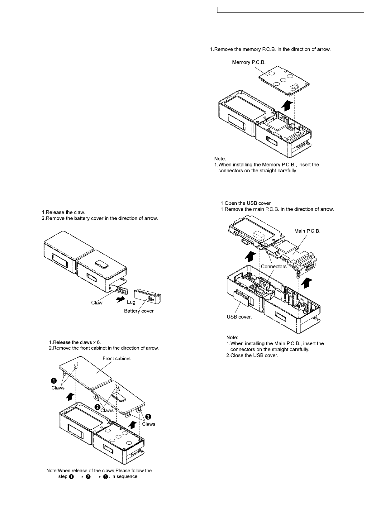
5.1. Removal of the battery cover
5.2. Removal of the front cabinet
5.3. Removal of the memory P.C.B.
5.4. Removal of the main P.C.B.
5.5. Removal of the battery terminal.
5.6. Removal of the LCD Ass 馳
5.7. Removal of the LCD Piece
5.8. Removal of the mode button and hold knob
5.9. Removal of the USB fix piece and USB cover
5.10. Removal of the REC button
5.11. Removal of the tuner P.C.B. and MIC ass 馳
6 Service Position
7 Service Mode
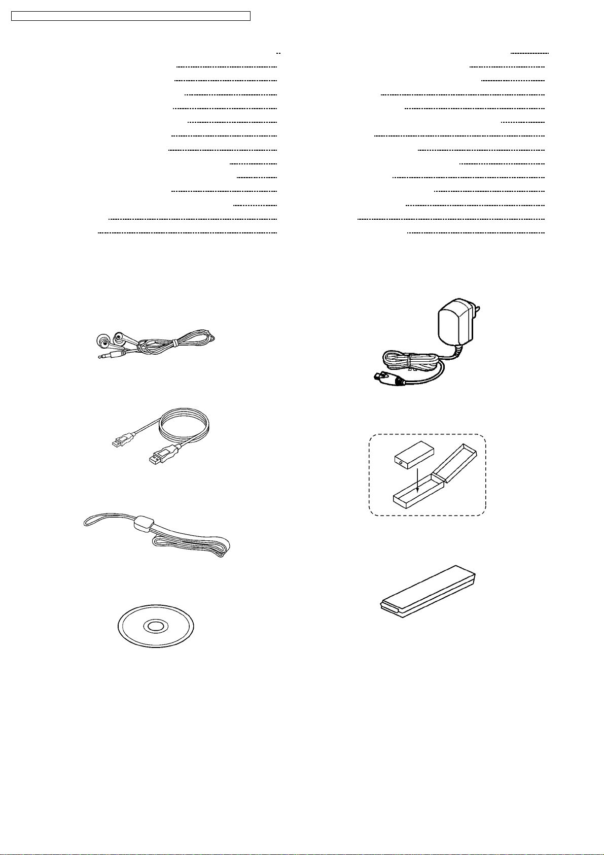
1 Accessories
· Stereo earphones
(L0BAB0000187) ............................................................ . 1pc.
7.1. Checking Procedures for IC3 C2DBGL000001 9
5
5
5
5
6
6
6
6
6
7
7
8
9
7.2. Checking Procedures for Fonttable
8 The Method of Download of DFU Software
9 Troubleshooting
10 Troubleshooting guide
11 Type Illustration of ICs, Transistors and Diodes
12 Block Diagram
13 Schematic Diagram Notes
14 Printed Circuit Board Diagram Notes
15 Schematic Diagram
16 Printed Circuit Board Diagram
17 Cabinet Parts Location
18 Packaging
19 Replaceme nt Parts List
10
11
15
15
16
17
22
22
23
28
32
33
34
· USB Cable
(K1HA05AD0003)............. ................................................ 1pc.
· Neck Strap
(RFAT0006-Q) .................................................. ................1pc.
· CD-ROM Driver
(RFE0164) ........................................................................ 1pc.
· Adaptor
(N0JECD000001) ...........................................................[GK].
(N0JECD000002) ...........................................................[GD].
(N0JECD000003) ...........................................................[GC].
(N0JECD000004) ...........................................................[GH].
(N0JECD000005) ...........................................................[GN].
· Battery Ass’y
(ZBRP-BP65HE)........................... .....................................1pc.
· Battery Case
(RFCT0005-H) .................................................. .......... 1pc.
2
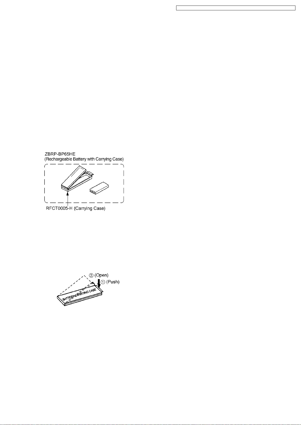
2 Supply of Rechargeable
Battery as Replacement
Parts
· Please take note of the following points relating to Carrying
Case to be used for protection of Rechargeable Battery
from shorting.
Replacement Parts:
· Rechargeable Battery (ZBRP-BP65HE) to be supplied will
be provided with Carrying Case (RFCT0005-H).
· No replacement parts will be supplied for Rechargeable
Battery without Case.
· Replacement parts will be supplied for Carrying Case
(RFCT0005-H) without Rechargeable Battery.
· To your customers, delivery Rechargeable Battery together
with Carrying Case to prevent shorting accidents that may
occur when Rechargeable Battery is carried about without
Carrying Case.
SV-MP500VGK / SV-MP500V GH / SV-MP500VGC / SV-MP500VGD / SV-MP50 0VGN
3 Caution in Use of
Rechargeable Battery
· Take Rechargeable Battery out of Carrying Case and use
iy. Be sure to carry Rechargeable Battery in this Carrying
Case. If not, may either head or ignite by shorting with a
metal.
3
SV-MP500VGK / SV-MP500V GH / SV-MP500VGC / SV-MP500VGD / SV-MP50 0VGN
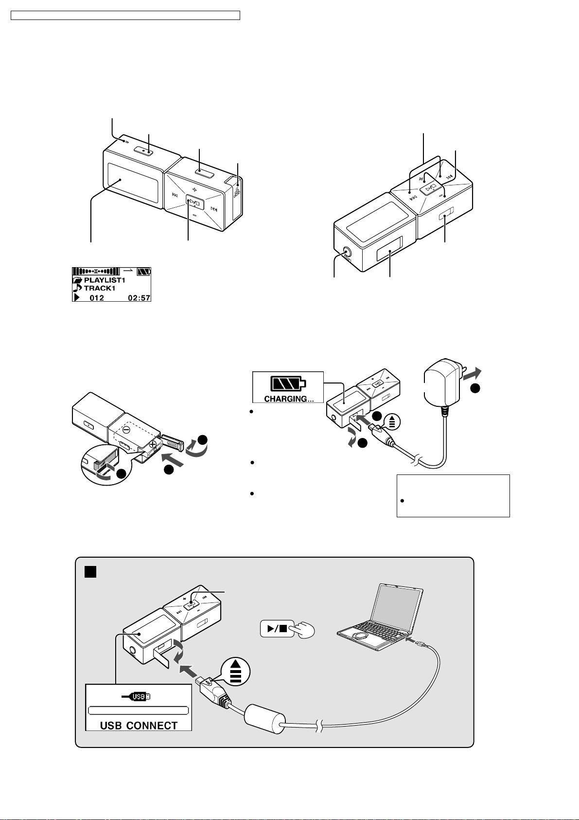
4 Location of Controls
Location of Controls
Microphone
REC/STOP
DMODE
Battery lid
Skip/search
Volume
Display
Example:MUSIC
Rechargeable battery (included)
Insert the
1
rechargeable battery.
1
Turn on, off (Press and hold)/
Play/Stop
2
"CHARGING"
3
2
Earphones jack
(3.5 mm stereo)
Charge before initial use
Charge the battery.
appears on the
display after
connecting the
adaptor.
Recharging also takes place when
the player is connected to a
computer's USB port.
Operation cannot be guaranteed if you
use a USB hub or extension cable.
AC
1
USB port
AC Adaptor
Insert so
2
the arrow
is facing
upwards
Recharging time:
The display will turn off when
recharging is complete.
HOLD
switch
3
To a
household
mains
socket
Approx. 6 hours
Connecting to a computer and downloading files
Connection
Press and hold
Turn the unit on.
1
¡÷into mode select
frame .
4
To USB
port
2
In s ert s o th e
3
arrow is fac in g
upwa rds.
4
Small end to
player, large
end to PC
SV-MP500VGK / SV-MP500V GH / SV-MP500VGC / SV-MP500VGD / SV-MP50 0VGN
5 Operation Checks and
Component Replacement
Procedures
1. This section describes procedures for checking the
operation of the major printed circuit boards and replacing
the main components.
2. For reassembly after operation checks or replacement,
reverse the respective procedures special ressembly
procedures are described only when required.
3. Select item from the following index when checks or
replacement are required.
Contents
1. Checking for the main P.C.B.
2. Checking for the memory P.C.B.
3. Checking for the tuner P.C.B.
4. Checking for the LCD ass’y.
5. Checking for the prevent electrostatic discharge.
5.1. Removal of the battery cover
5.3. Removal of the memory P.C.B.
5.4. Removal of the main P.C.B.
5.2. Removal of the front cabinet
5
SV-MP500VGK / SV-MP500V GH / SV-MP500VGC / SV-MP500VGD / SV-MP50 0VGN
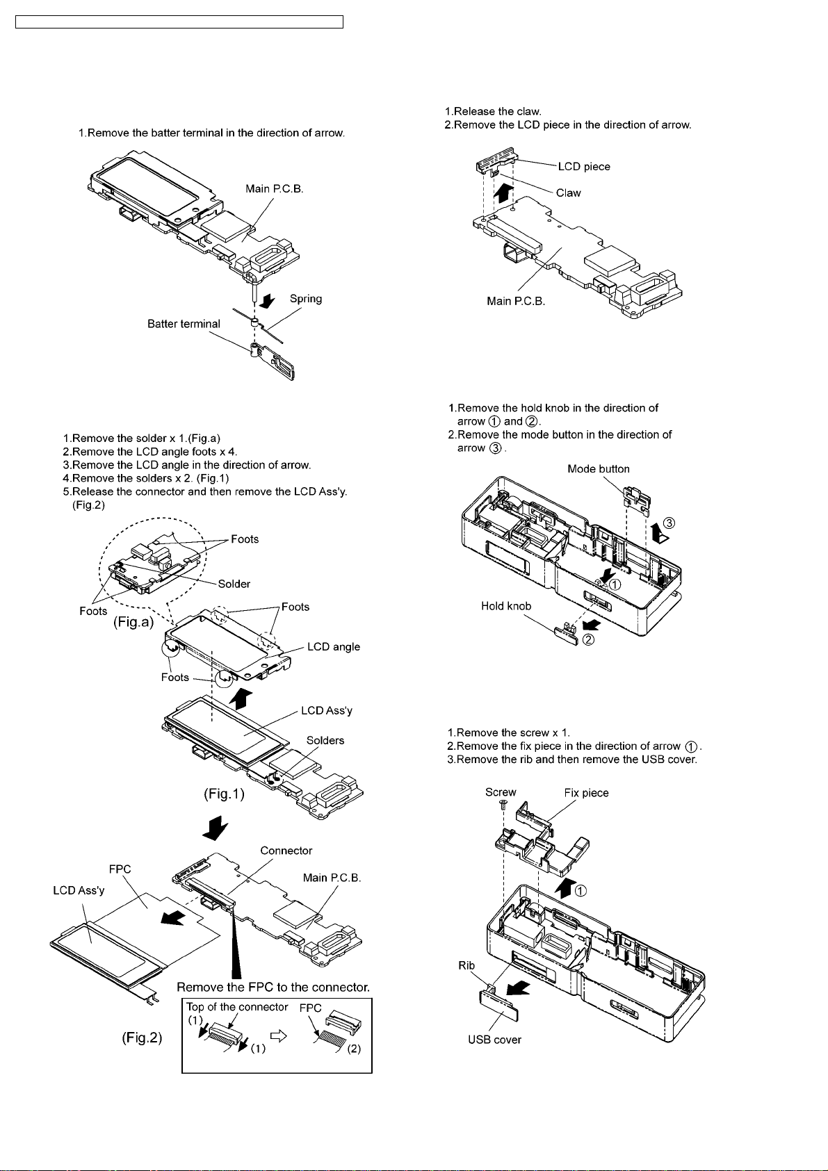
5.5. Removal of the battery
terminal.
5.6. Removal of the LCD Ass’y
5.7. Removal of the LCD Piece
5.8. Removal of the mode button
and hold knob
5.9. Removal of the USB fix piece
and USB cover
6
SV-MP500VGK / SV-MP500V GH / SV-MP500VGC / SV-MP500VGD / SV-MP50 0VGN
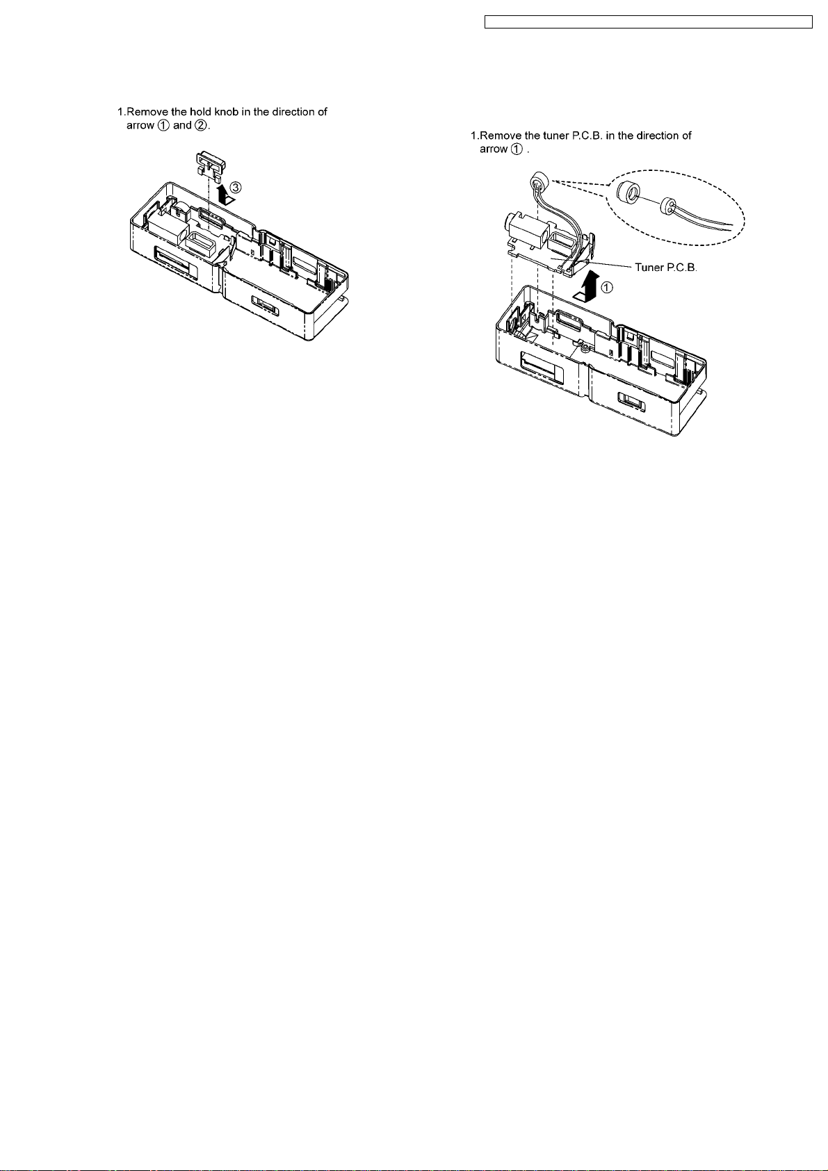
5.10. Removal of the REC button 5.11. Removal of the tuner P.C.B.
and MIC ass’y
7
SV-MP500VGK / SV-MP500V GH / SV-MP500VGC / SV-MP500VGD / SV-MP50 0VGN
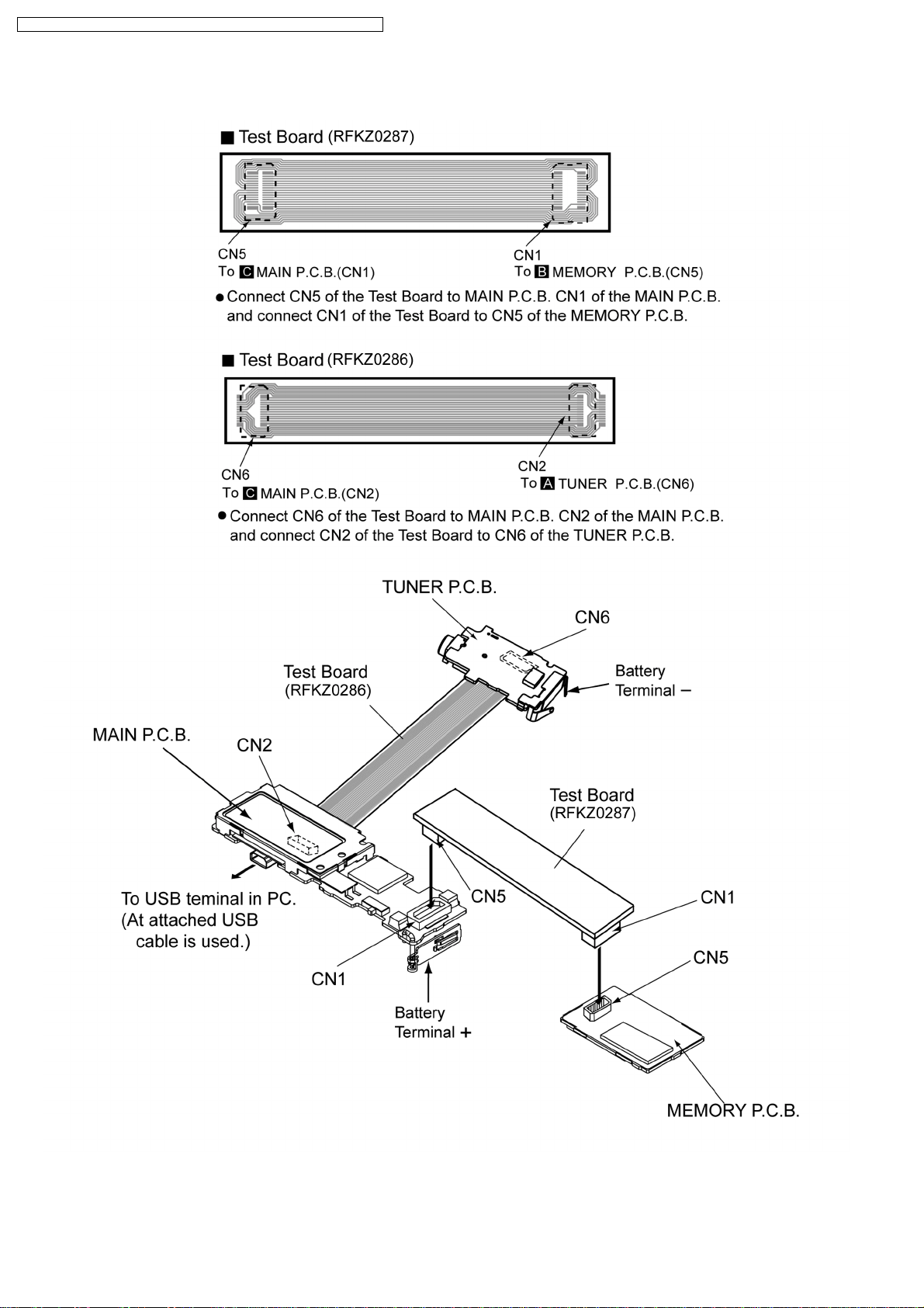
6 Service Position
8
SV-MP500VGK / SV-MP500V GH / SV-MP500VGC / SV-MP500VGD / SV-MP50 0VGN
7 Service Mode
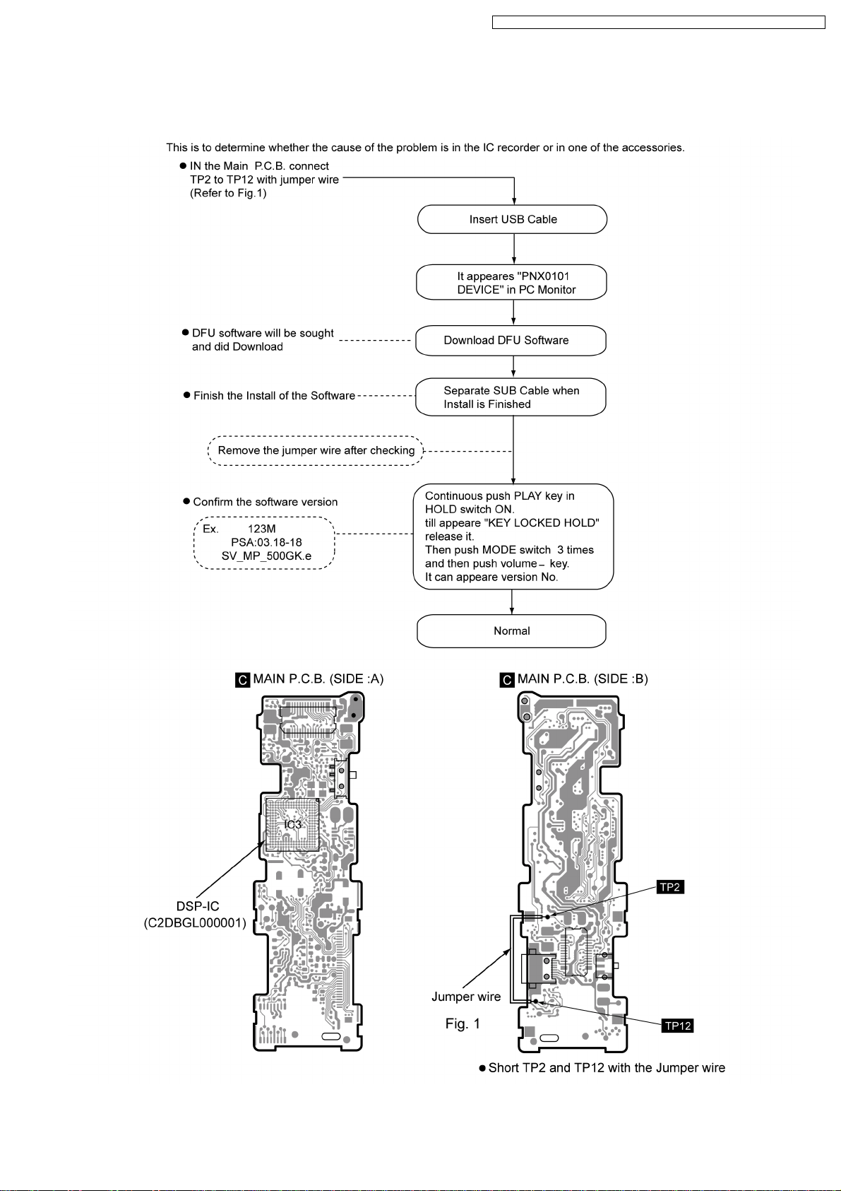
7.1. Checking Procedures for IC3 C2DBGL000001
9
SV-MP500VGK / SV-MP500V GH / SV-MP500VGC / SV-MP500VGD / SV-MP50 0VGN
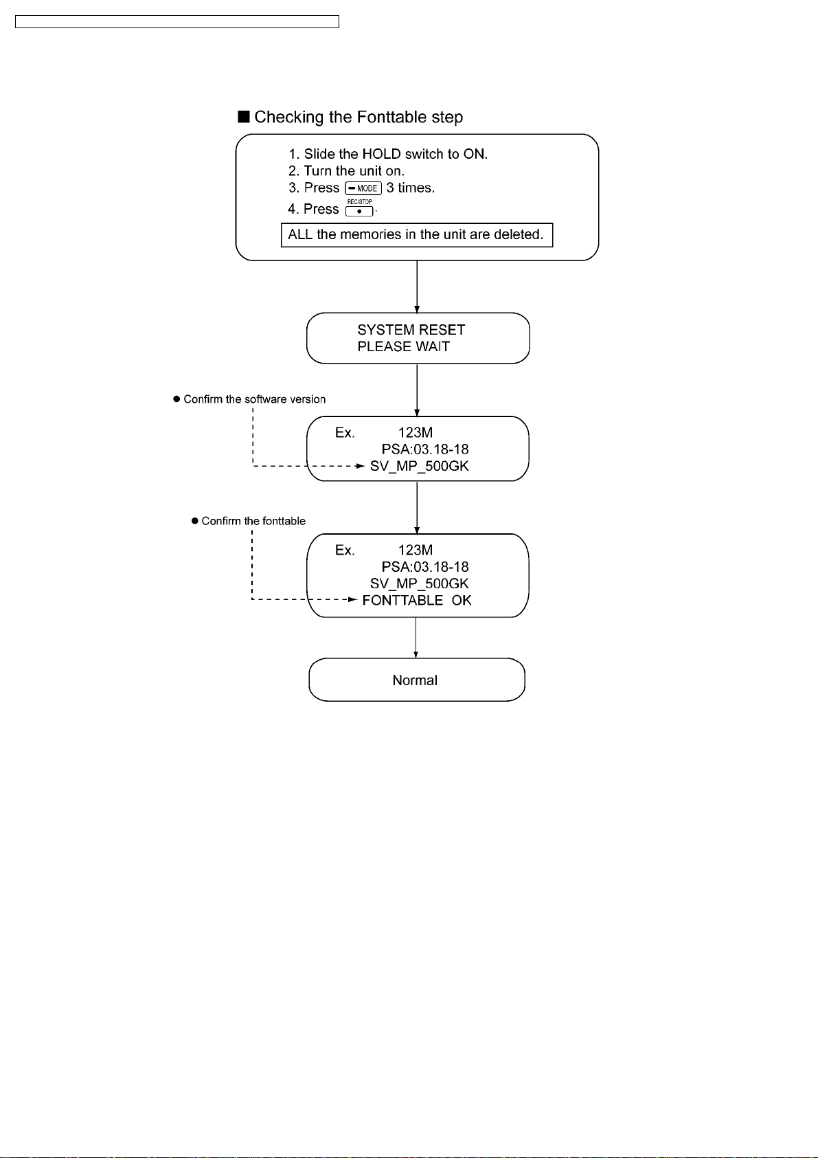
7.2. Checking Procedures for Fonttable
10
SV-MP500VGK / SV-MP500V GH / SV-MP500VGC / SV-MP500VGD / SV-MP50 0VGN
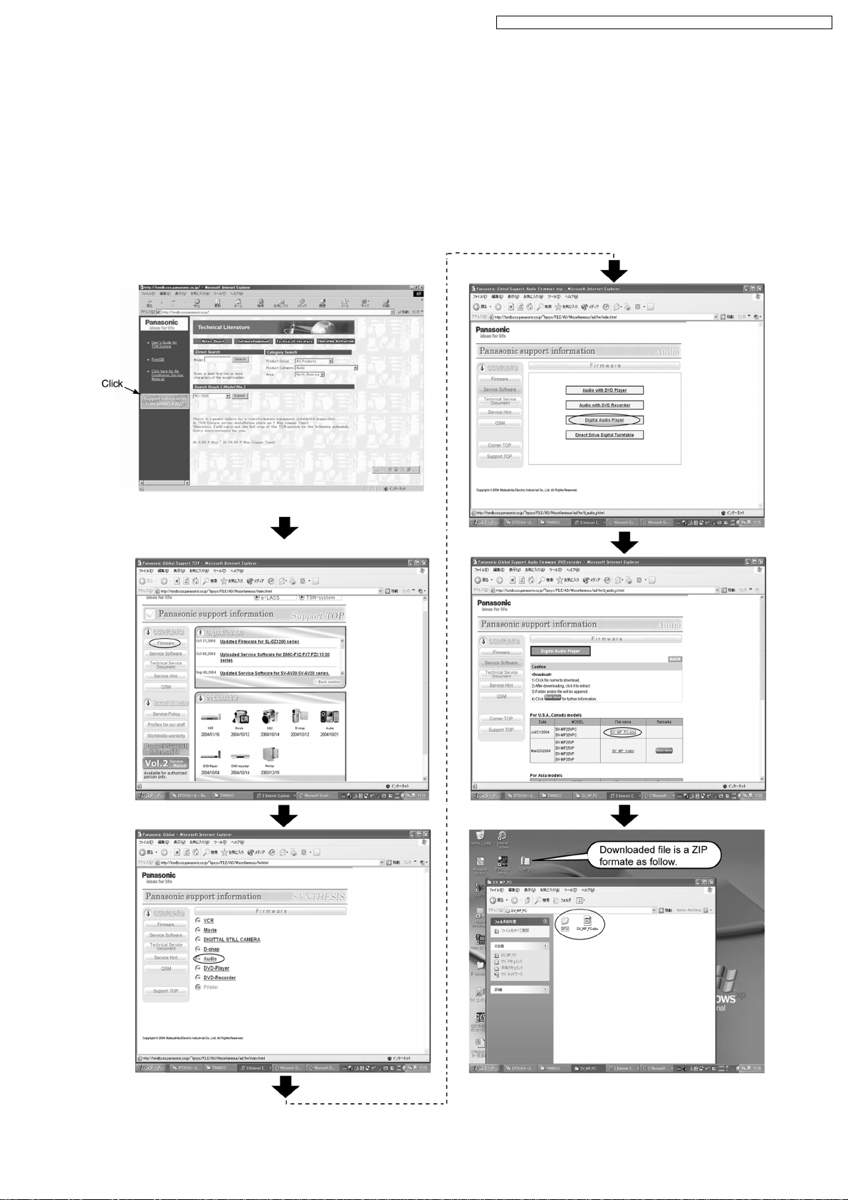
8 The Method of Download of DFU Software
1. The “DFU Applications” is downloaded from TSN SYSTEM.
a. TSN SYSTEM (URL---http://tsndb.css.panasonic.co.jp) is opened.
b. “<Support Information from NWBG-PAVC>” is clicked.Fig.1
c. “↓CONTENTS <Firmware>” is clicked.
d. “→AUDIO” is clicked.
e. “Digital Audio Player” is clicked.
f. Following, please download according to directions of a screen.
Fig.1
11
 Loading...