

Panasonic SR-GA281, SR-GA721 service manual
Service Manual
Order No. PHAT070510C3
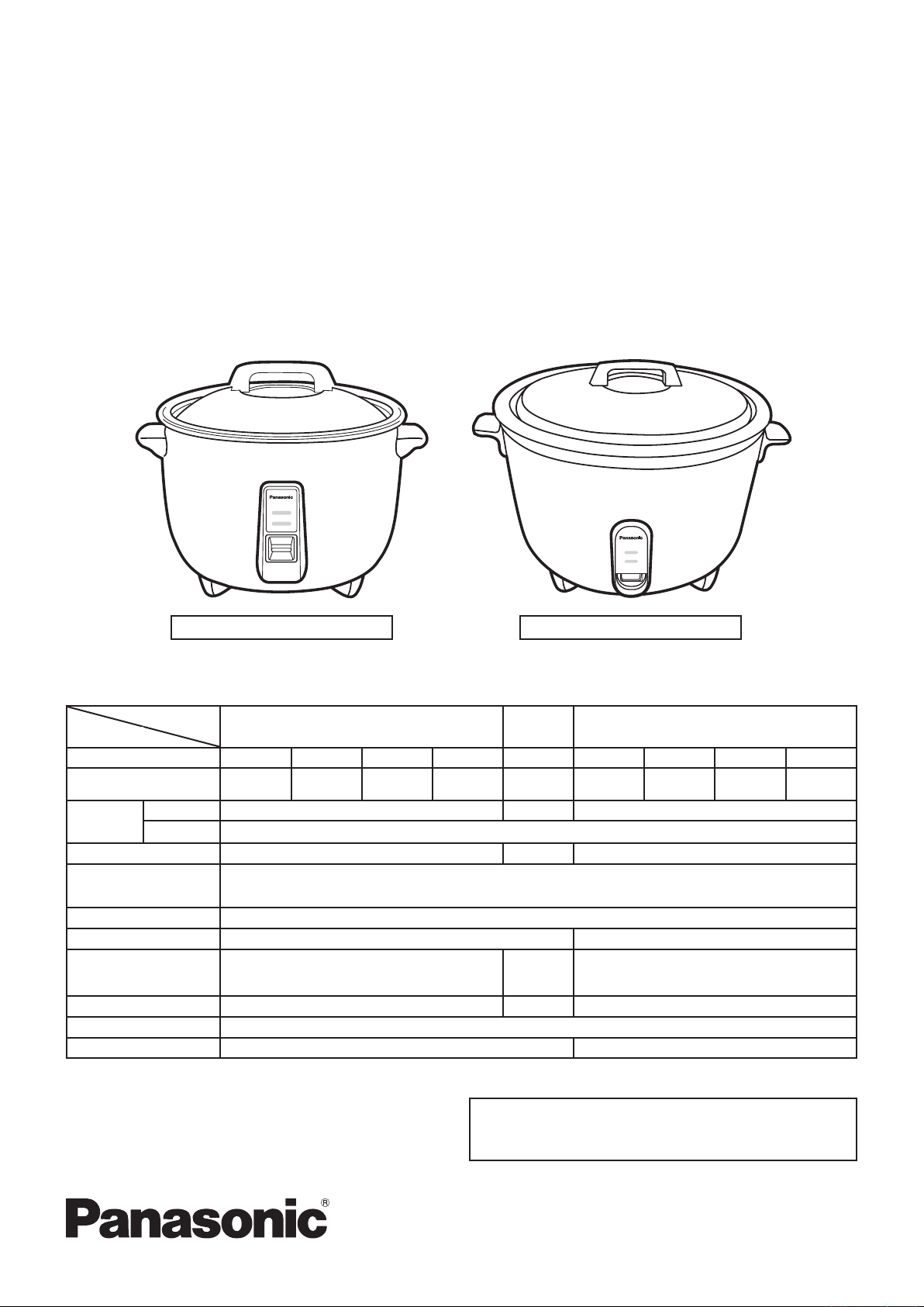
Automatic Rice Cooker
SR-GA421/SR-GA281/SR-GA721
EXPORT
© 2007 Panasonic Home Appliance (Thailand) Co.,Ltd
All rights reserved. Unauthorized copying and distrbution
is a violation of law.
Specification
Specification subject to change without notice.
Model
SR-GA421 SR-GA281 SR-GA721
Detail
Country HK SIN-DBD SIN-RBD MALAYSIA HK MALAYSIA SIN-DBD SIN-RBD USA
Power Source
220 V / 50 Hz 230 V / 50 Hz 220 V / 50 Hz 240 V / 50 Hz 220 V / 50 Hz 240 V / 50 Hz 230 V / 50 Hz 220 V / 50 Hz 208 V / 50 Hz
Power
consumption
Cooking 1400 W 950 W 2500 W
Warming
47.5 W
Cooking capacity 5 ~ 23 L 5 ~ 15 L 3 ~ 7 L
Center thermostat
working temperature
140 °C
Keep warm temperature More than equal to 80 °C (After 1 Hr. keep warm)
Thermal fuse specification 113
169 °C
Dimension (mm)
Width x Depth x Height 429 x 369 x 300
367
x 295
x 305
248 x 247 x 255
Weight
5.5 kg 3.6 kg 10.1 kg
Power Cord (approx.) 1.0 m
Accessories Measuring cup, Steaming basket Rice scoop
COOK
WARM
Rice Cooking
Keep Warm
SR-928
SR-GA421/SR-GA281 SR-GA721
2
SR-GA421/SR-GA281/SR-GA721
WARNING
This service information is designed for experienced repair technicians only and is not designed for use by the general public.
It does not contain warnings or cautions to advise non-technical individuals of potential dangers in attempting to service a product.
Products powered by electricity should be serviced or repaired only by experienced professional technicians. Any attempt to service or
repair the product or products dealt with in this service information by anyone else could result in serious injury or death.
There are special components used in this equipment which are important for safety. These parts are marked by
in the Schematic
Diagrams, Circuit Board Diagrams, Exploded Views and Replacement Parts List. It is essential that these critical parts should
be replaced with manufacturer’s specified parts to prevent shock, fire or other hazards. Do not modify the original design without
permission of manufacturer.
IMPORTANT SAFETY NOTICE
CONTENTS
1.SCHEMATIC DIAGRAM & WIRING DIAGRAM .....................................................................3-4
2.FUNCTION OF CENTER THERMOSTAT AND THERMAL FUSE .........................................
5-6
3.TROUBLE SHOOTING GUIDE ...............................................................................................7-8
4.TESTING PROCEDURE .........................................................................................................9-10
5.EXPLODED VIEW & PACKING VIEW (SR-GA421/SR-GA281) ............................................11-12
6.REPLACEMENT OF PARTS LIST & PACKING LIST
(SR-GA421/SR-GA281) ....................13-14
7.EXPLODED VIEW & PACKING VIEW (SR-GA721) ..............................................................15-16
8.REPLACEMENT OF PARTS LIST & PACKING LIST
(SR-GA721) .......................................17-18
Page
3
SR-GA421/SR-GA281/SR-GA721
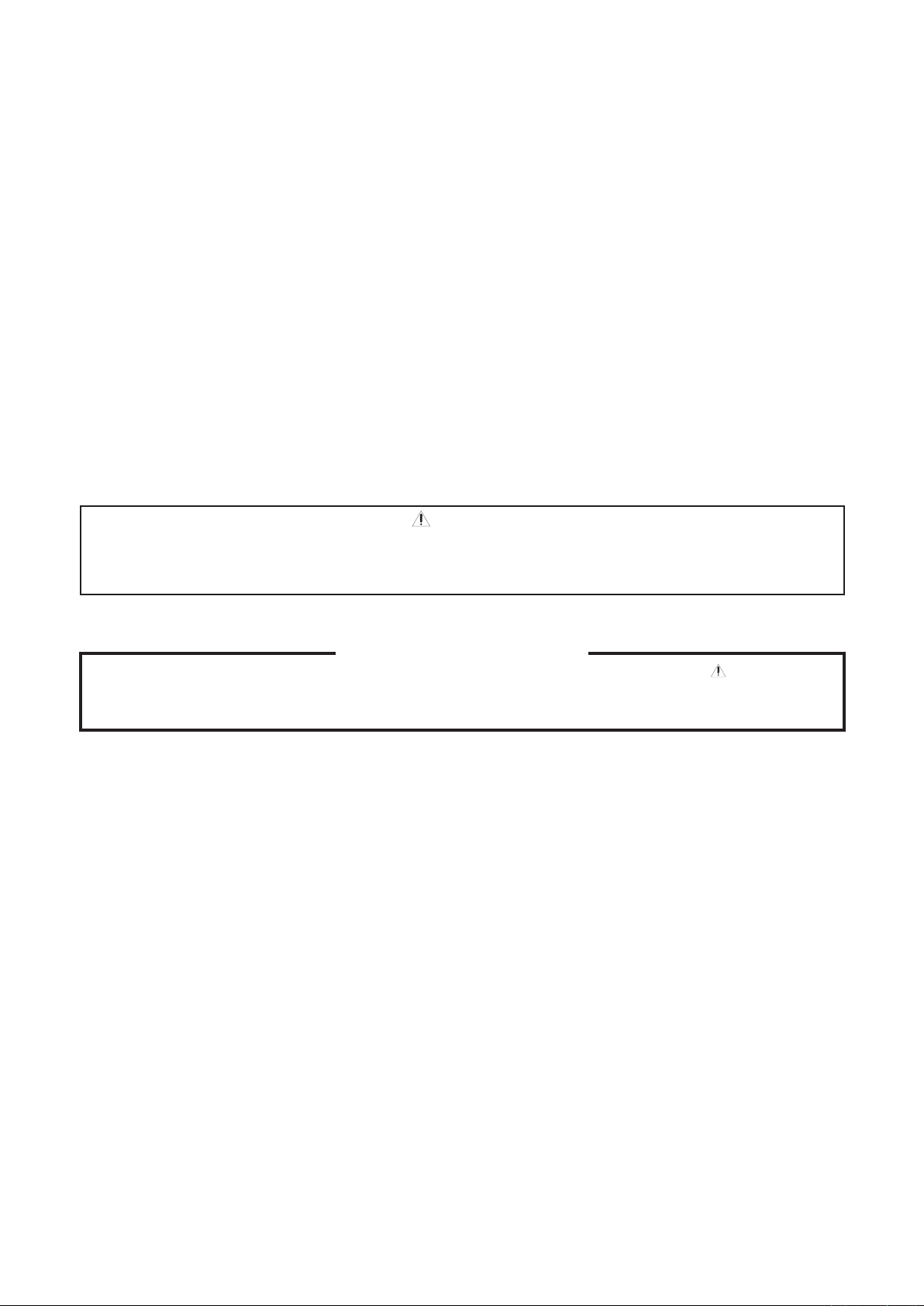
L
N
MICA HEATER ASS’Y
CAST HEATER
LAMP RESIST
.
T.F.
INPUT
SWITCH
LAMP RESIST.
KEEP WARM NEON LAMP
(BIG)
(SMALL
)
E
Green
RICE COOKING NEON LAMP
Lamp Lead Wire A (Orange)
Lead Wire (Orange)
Lamp Lead Wire C (Brown)
Twist one time
Lamp Lead Wire B (Gray)
Lever Earth Lead Wire (Green)
Silicone Tube (Blue)
N
Twist two time
Thermal Fuse Wire (Gray)
Switch Lead Wire (Blue)
Cord Wire Earth (Green)
Silicone Tube (Green)
Silicone Tube (Brown)
Cord Bush
1
0
˚
±
5
˚
Thermal Fuse Wire (Brown)
N
Cord Bush
Silicone Tube (Blue)
Silicone Tube (Brown)
After ass’y, Mica Heater Ass’y must not overlie
the Outer Case of Center Thermostat
.
Water guard
Cord Wire Earth (Green)
Silicone Tube (Green)
Thermal Fuse Wire (Blue)
Lever Earth Lead Wire (Spiral Green)
Wiring Lead Wire (Brown
)
Lamp Lead Wire A (Red
)
Lamp Lead Wire C (Brown
)
Twist one time
Thermal Fuse Wire (Gray)
Lamp Lead Wire B (Gray)
After assembly Mica Heater case
Must no touch the terminal of cast heat
.
Glass tape 20 x 20 mm
.
After as
s’y, gap between terminal and mica heater case must be more than 4 mm.
1
0
˚
±
5
˚
Cast Heater
Lamp Resistor
Lamp Resistor
Switch
Keep Warm Neon Lamp
Rice Cooking Neon Lam
p
Gra
y
Input
Blue
Brown
N
L
E
Gree
n
Mica Heater Ass’y
T.F. T.F.
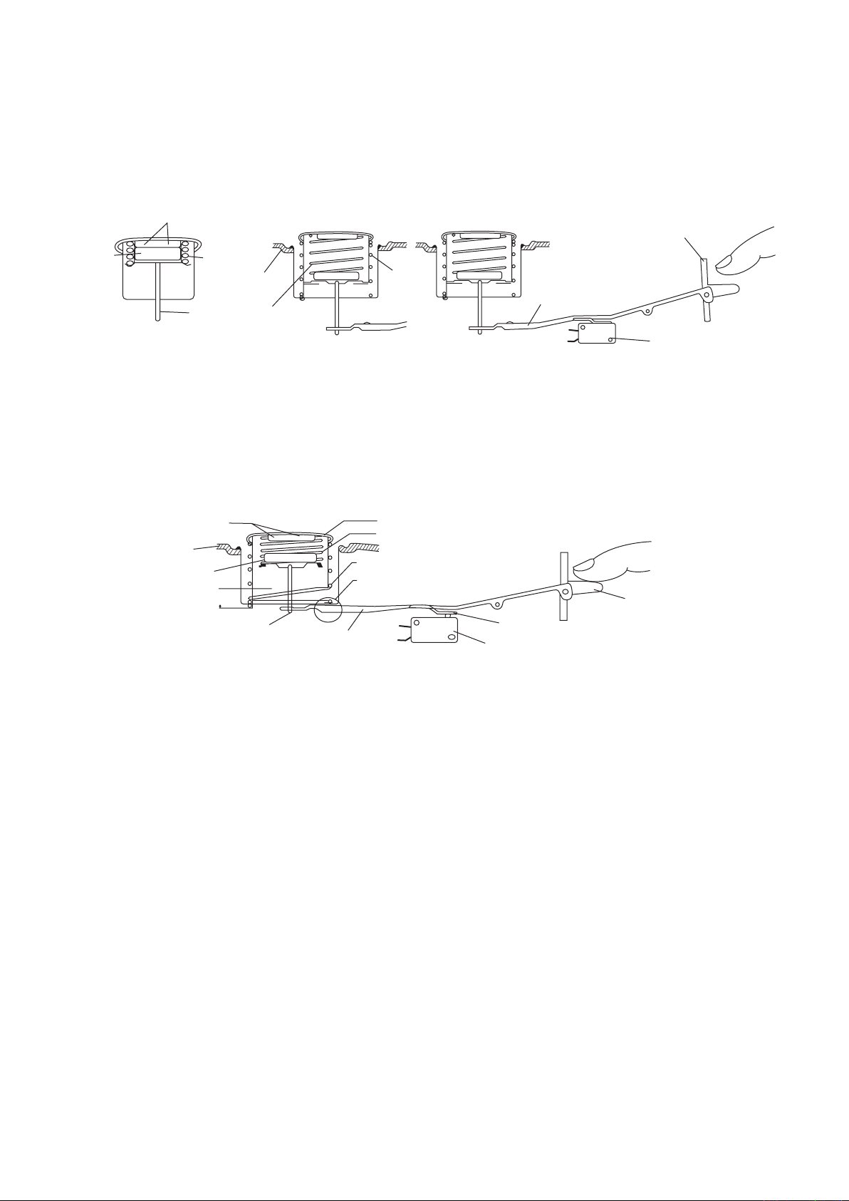
1. SCHEMATIC DIAGRAM & WIRING DIAGRAM
SCHEMATIC DIAGRAM (SR-GA421) WIRING DIAGRAM (SR-GA421)
SCHEMATIC DIAGRAM
(SR-GA281) WIRING DIAGRAM (SR-GA281)
4
SR-GA421/SR-GA281/SR-GA721
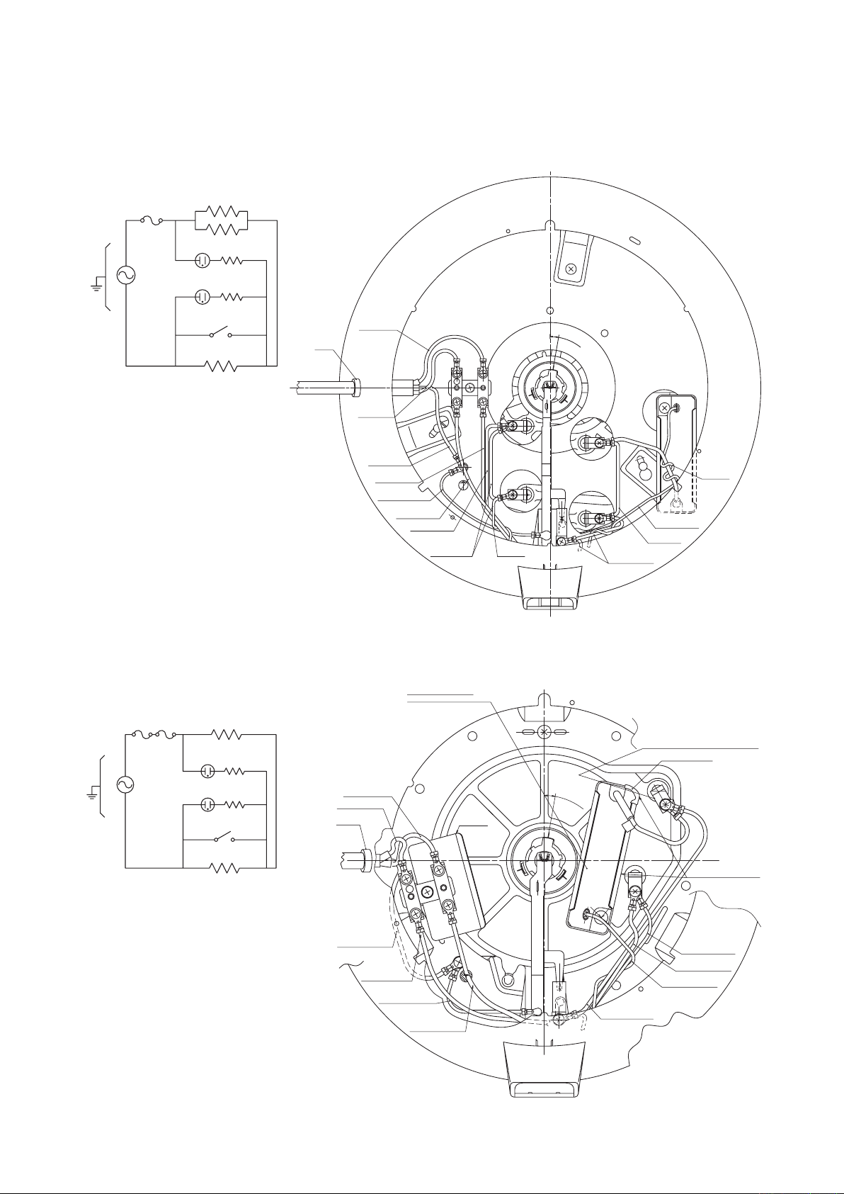
Cord Wire Earth (Green)
Cord Wire Blue (N)
Cord Wire Brown (L)
Heater lead wire B (grey)
Thermal fuse lead wire (Blue)
Thermal fuse lead wire (Grey
)
User positio
n
Heater lead wire C (Brown
)
Heater lead wire A (Red)
Grey
Brown
Red
Cathode lead wire (Brown
)
Keep warm lamp lead (Red
)
1
0
˚
±
5
˚
MICA HEATER ASS’Y
CAST HEATER
LAMP RESIST.
SWITCH
LAMP RESIST.
KEEP WARM NEON LAMP
RICE COOKING NEON LAMP
(SMALL)
(MIDDLE)
(BIG)
E
Green
INPUT
L
N
Brown
Blu
e
1
.
F.
T2.
F
.
T
1. SCHEMATIC DIAGRAM & WIRING DIAGRAM
SCHEMATIC DIAGRAM (SR-GA721)
WIRING DIAGRAM (SR-GA721)
5
SR-GA421/SR-GA281/SR-GA721
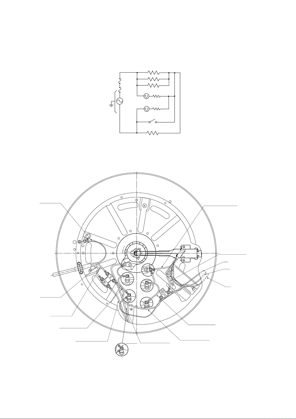
2.
FUNCTION OF CENTER THERMOSTAT AND THERMALFUSE
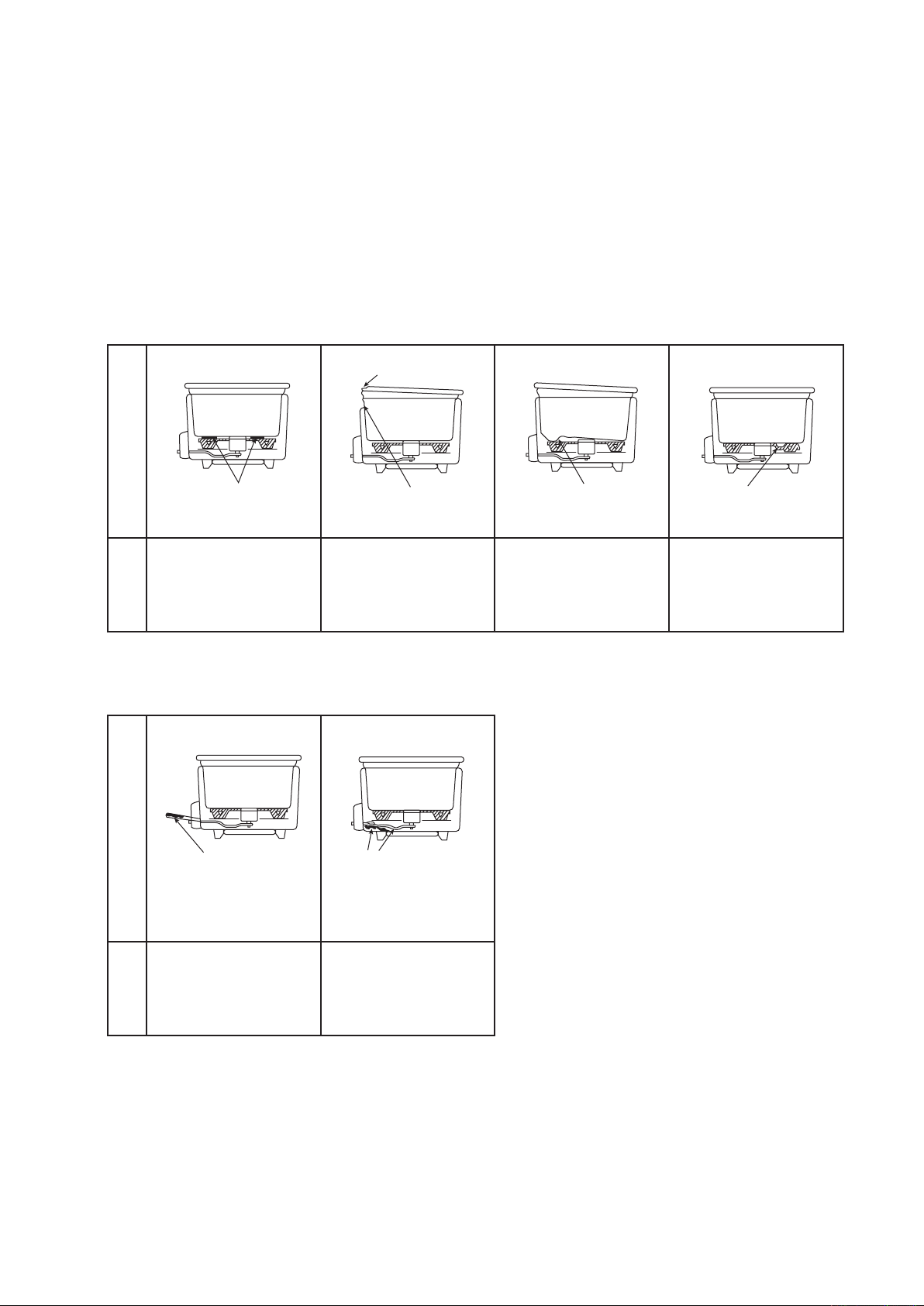
A. Center Thermostat
The center thermostat senses when the bottom of the rice cooker pan reach 134°C ± 6°C.
And it’s action turns off the cooking cycle, and starts the warming cycle.
Refer to these figures showing the center thermostat construction and cooking position. As
the metal is heated, its ability to be attracted by the magnet decreases.
Finally, the inner spring pressure becomes stronger than the magnetic pull and the metal
and magnet will pop apart. The rod activates the switch lever which causes the auxiliary lever to
press the micro-switch button into the warming cycle.
B. Switch-On Preventive System
This is design to prevent the rice cooker from being turned on without the pan placed into
position.
1) Normally when the pan is inserted properly into the rice cooker, the pan will depress the
center thermostat. The center thermostat outer spring will be compressed. In this case when
the switch button is depressed, the following will happen:
a. The auxiliary lever will release the micro-switch button. This puts the micro-switch in the
cook position.
b. The switch lever will push the rod which will allow the magnet to meet with the metal.
c. When the rice is cooked and the proper temperature has been reached 134°C ± 6°C, the
metal and magnet will pop apart as described in the center thermostat operation above.
d. The rod will push the switch lever and cause the auxiliary lever to depress the micro-
switch button. This puts the micro-switch in the warming position.
2) When the pan is not in place within the rice cooker, the center thermostat is not depressed.
a. In this condition, the outer spring is not compressed within the center thermostat
preventing the metal from reaching its normal operating position.
b. When the switch button is depressed, the switch lever and auxiliary lever work as above
but the magnet cannot come in contact with the metal to hold the switch lever in the cook
position. This happens because the switch lever hits the thermostat case and cannot push
the rod, with the magnet attached, all they way up to meet with the metal.
c. When the pressure is taken off the switch button, the switch lever releases immediately to
the open or warm positions.
Metal
Magnet
Inner spring
Cooking heater
Rod
10mm
Outer spring
Switch lever
Cook switch button
Micro switch
Thermostat case
Thermostat surface
Auxiliary lever
Metal
Magnet
Inner spring
Cooking heater
Rod
Inner spring
Outer
spring
Switch lever
Cook switch button
Micro switch
NC
C
Center thermostat construction
(Cooking Position) (Warming or Off Position)
Figure 1
6
SR-GA421/SR-GA281/SR-GA721
C. Thermal Fuse
The thermal fuse is used to open the circuit to the cooking heater when the temperature has
gone unusually high. This happens in cases such as incomplete contact between the heater
and pan or if the switch buttons is forced to stay on keeping the heater energized abnormally.
This fuse is not a resetting device and must be replaced after openning.
Whenever replacing the fuse make sure the protective cover is placed over all exposed wiring.
Cause of Fusion
[A] Improper contract between heater and pan
2.
FUNCTION OF CENTER THERMOSTAT AND THERMALFUSE
[B] Forced application of current
Cause
Pan collar or deformed
Foreign matter adhering Body dented or deformed Pan bottom dented or
deformed
Heater surface deformed
or corroded
Remedy
Remove foreign matter
by of (-) screw-driver,
etc., and then polish with
= 320 water paper while
wetting it with water.
Repair or replace body.
Replace pan. Replace cooking heater.
Cause
Chopstick, wooden
piece, etc. inserted onto
cooking button. (continuous application of current)
Switch lever deformed
or maladjusted, causing
continuous application of
current.
Remedy
Inserted to prevent earlier turning off? Refer to
cause in (a) above.
Repair or replace parts.
When fusion takes place, check the cause, set right the faulty section, and be sure to use
replacement parts.
 Loading...