

Page 1
© Copyright 1999 American Fibertek, Inc.
Table of Contents
SR-20, SR-20 R,
PSR-1, PSR-1M, PSR-1S
Sub-Rack, Power Supply
Instruction Manual
Page 2
Specifications................................................................................... 3
SR-20, SR-20R
PSR-1, PSR-1M, PSR-1S
Warranty............................................................................................ 3
SR-20, SR-20R Installation And Operation..................................... 4
Functional Description
System Compatibility
Installation
Power Supply
Service Information
PSR-1, PSR-1M, PSR-1S Installation and Operation..................... 5
System Compatibility
Line Voltage
Installation
Options
Controls and Indicators
Redundant Operation
Service Information
Specifications SR-20, SR-20R
Plug-in Cards SR-20 14
2
Page 3

Plug-in Cards SR-20R 11
Size 19” x 5 ¼” x 9”
Weight 4 ½ lbs.
Specifications PSR-1, PSR-1M, PSR-1S
Min Typ. Max
Line Voltage 115VAC 108 115 128 Volts AC
Line Voltage 230VAC 207 230 253 Volts AC
Current 115VAC 0.80 A
Current 230VAC 0.40 A
Frequency 47 63 Hz
Power 100 Watts
Operating Temperature 0 to 50 °C
Operating Humidity 0 to 90% non Condensing
Weight 10 lbs.
LIFETIME WARRANTY INFORMATION
American Fibertek, Inc warrants that at the time of delivery the products delivered will be
free of defects in materials and workmanship. Defective products will be repaired or
replaced at the exclusive option of American Fibertek. A Return Material Authorization
(RMA) number is required to send the products back in case of return. All returns must
be shipped prepaid. This warranty is void if the products have been tampered with. This
warranty shall be construed in accordance with New Jersey law and the courts of New
Jersey shall have exclusive jurisdiction over this contract. EXCEPT FOR THE
FOREGOING WARRANTY, THERE IS NO WARRANTY OF MERCHANTABILITY OR
FITNESS FOR A PARTICULAR PURPOSE OR OTHERWISE, EXPRESSED OR
IMPLIED, WHICH EXTENDS BEYOND THE WARRANTY SET FORTH IN THIS
AGREEMENT. In any event, American Fibertek will not be responsible or liable for
contingent, consequential, or incidental damages. No agreement or understanding,
expressed or implied, except as set forth in this warranty, will be binding upon American
Fibertek unless in writing, signed by a duly authorized officer of American Fibertek.
INSTALLATION AND OPERATION INSTRUCTIONS
SR-20, SR-20R Sub-rack Frame
FUNCTIONAL DESCRIPTION
3
Page 4

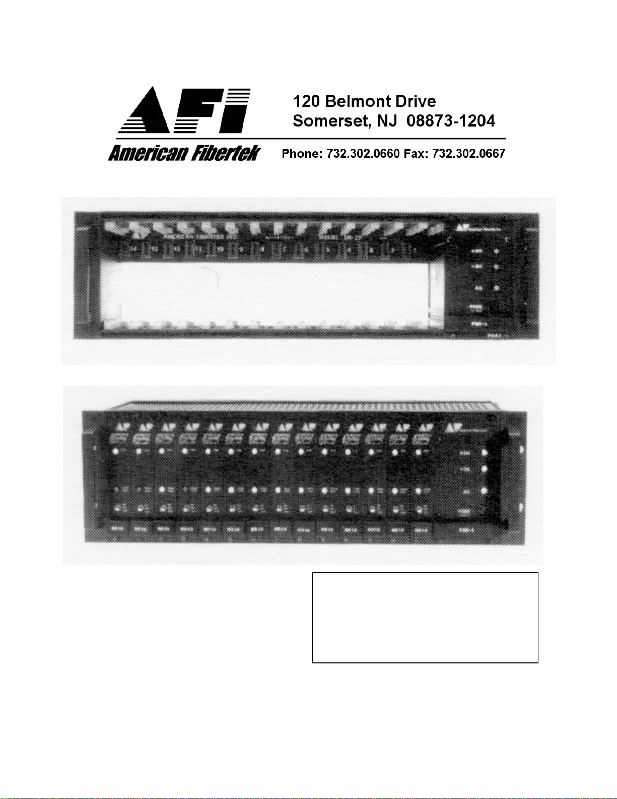
The SR-20 sub-rack is a standard 19" x 5.25" frame designed to accommodate up to
fourteen fiber optic plug-in cards along with a PSR-1 series power supply. the SR-20R
Redundant Power Supply frame can accommodate up to eleven plug-in cards.
SYSTEM COMPATIBILITY
Any plug in card with the model number beginning with the letter "R" can be inserted into
any of the fourteen application slots on the left-hand side of the SR-20. (Eleven slots for
the SR-20R.)
INSTALLATION
THIS INSTALLATION OF THIS UNIT SHOULD BE MADE BY A QUALIFIED SERVICE
PERSON(S) AND MUST CONFORM TO ALL LOCAL CODES.
The SR-20 may be mounted, using standard hardware, in an upright position, with the
backplane upward, inside the cabinet (see diagram below). It is important, as with any
electronic equipment, to provide sufficient airflow to prevent over heating in the cabinet.
At least 1 7/8" (1RU) of space should be allowed above and below the SR-20 to provide
air flow. If more than one SR- 20 is installed, forced airflow may be necessary depending
upon the number of plug-in cards used in the over-all installation. It is necessary to add
a 1RU fan unit at the top of every three SR-20 sub-racks with 1U spacing between them.
All applications cards are inserted in a similar manner. Any card may be used in any slot.
Insert the card all the way until the edge fingers meet the internal bus connector and the
front panel is even with the front of the sub-rack. Then secure the ¼ turn fasteners by
pushing with a small screwdriver, turning the screw 90 degrees clockwise and releasing
pressure.
POWER SUPPLY
The far right hand position of the SR-20 is only compatible with a PSR-1 series plug in
power supply. Please refer to PSR-1 instructions. The SR-20R allows for two power
supplies operating as automatic takeover redundant supply configuration. A PSR-1
Master and PSR-1 Slave are required for this feature. For details, see the PSR-1
instructions or consult the factory.
SERVICE INFORMATION
Please refer all service inquiries to:
AMERICAN FIBERTEK,INC
120 Belmont Drive
Somerset, NJ 08873
Phone (732) 302-0660
FAX (732) 302-0667
E-mail techinfo@americanfibertek.com
INSTALLATION AND OPERATION INSTRUCTIONS
PSR-1, PSR-1M, PSR-1S Plug-in Power Supplies
SYSTEM COMPATIBILITY
Up to fourteen plug in cards can be powered by the PSR-1.
LINE VOLTAGE
4
Page 5

The input line voltage should be a nominal 115 VAC or 230 VAC, 47 - 63 Hz power
source, properly grounded and conforming to all local codes. A universal power
connector is provided on the rear of the unit to facilitate connection to the power mains.
INSTALLATION
This installation should be made by a qualified service person. All wiring methods should
be in accordance with the National Electric Code, ANSI/NFPA 70. Before inserting the
PSR-1 the line voltage selector switch must be set to the proper line setting. A small
screwdriver may be used. The unit slides in and is locked into place by four ¼ turn
fasteners. The line cord is then plugged in from the rear. Be sure that the power switch is
in the off (O) position before connecting the power source.
OPTIONS
Optional features include redundant supplies with automatic take-over. An SR-20R is
required for this feature. Also two supplies (master and slave) are required. The Master
supply powers the system as the Slave monitors the power bus. In the event of an over
voltage or under voltage condition, the Slave supply will disconnect the Master from
the bus.
CONTROLS AND INDICATORS
Front panel LEDs indicate positive (+DC) and negative (-DC) voltages and the AC line
(AC) being present.
Also available on the front panel, is the line fuse. A 5 X 20 millimeter fast blow type
should be used. There is a spare fuse behind the front handle. It is accessible by
removing the supply and sliding the plate to either side. Insert the handle cover back to
the original position and replace the unit. Qualified personnel should only attempt fuse
replacement.
CAUTION: FOR CONTINUED PROTECTION AGAINST RISK OF FIRE, REPLACE
ONLY WITH THE SAME TYPE FUSE. For 115VAC operation a 1A fuse is required. For
230VAC operation a 0.5A fuse rating is required.
The ON/OFF switch is located on the rear of the unit. Be sure the switch is in the off (O)
position before connecting to the power source. Please note that this supply is intended
5
Page 6

to be used with, and only when inserted into, an SR-20 or SR-20R sub-rack frame. Even
though the output connector is recessed, there is potential for high current at the output.
The sub-rack SR-20 is supplied with a three-conductor power cord. The Ground
conductor is directly connected to the chassis. See safety instructions.
REDUNDANT OPERATION
A Master supply will not function without a Slave supply present. The Master and Slave
supplies may be inserted into either of the two power supply slots provided by the SR20R (See INSTALLATION section). Due to the space required for the second PSR, the
SR-20R will only accommodate eleven plug-in applications cards.
To turn the system "ON" it is necessary to turn the master supply on first. The slave
supply is then powered and will monitor the master supply output.
Linear voltage sensing in the slave supply monitors both polarities of the master output.
In the event of master supply failure, the slave supply will take over, disconnecting the
master supply from the distribution bus in the rear of the sub rack frame.
When the slave supply takes over its LED indicators will illuminate. The LED indicators
on the master supply may or may not have its LEDs on.
Upon replacing a failed master or to reset the system the following steps are to be taken:
1. Be sure both master and slave are properly inserted into
the sub rack frame.
2. Apply power to the master supply.
3. Turn slave "OFF" for 5 (five) seconds.
4. Apply power to the slave supply. (The LEDs should not
illuminate.)
SERVICE INFORMATION
In the event of required service to this unit; please direct all inquiries to:
American Fibertek, Inc. Phone: (732) 302-0660
120 Belmont Drive FAX (732) 302-0667
Somerset, NJ 08873 E-mail: techinfo@americanfibertek.com
GRAPHICAL SYMBOLS
6
Page 7

7
 Loading...