

Panasonic SQ4-C11 Installation Manual
INSTRUCTION MANUAL
Controller for Safety Liquid Leak Sensor SQ4-A Series
SQ4-C11
© Panasonic Electric Works SUNX Co., Ltd. 2010 MJE-SQ4C11 No.0017-23V

(MEMO)
1 © Panasonic Electric Works SUNX Co., Ltd. 2010 MJE-SQ4C11 No.0017-23V
Thank you for purchasing Panasonic Electric Works SUNX’s controller SQ4-C11 for safety liquid
leak sensor SQ4-Asereis.
Read this instruction manual carefully and thoroughly for the correct and optimum use of this
device.
Kindly keep this manual in a convenient place for quick reference.
This device is a special controller of safety liquid leak sensor SQ4-Asereis.
This manual has been written for the following personnel who have undergone suitable training
safety
and have knowledge of
liquid leak sensors, as well as, safety systems and standards.
● who are responsible for the introduction of this device
● who design the system using this device
● who install and connect this device
● who manage and operate a plant using this device
Notes
1) All the contents of this instruction manual are the copyright of the publishers, and may
not be reproduced (even extracts) in any form by any electronic or mechanical means
(including photocopying, recording, or information storage and retrieval) without permission in writing from the publisher.
2) The contents of this instruction manual may be changed without prior notice for further
improvement of the device.
3) Though we have carefully drawn up the contents of this instruction manual, if there are
any aspects that are not clear, or any error that you may notice, please contact our local
Panasonic Electric works SUNX offi ce of the nearest distributor.
4) English and Japanese are original instructions.
© Panasonic Electric Works SUNX Co., Ltd. 2010 MJE-SQ4C11 No.0017-23V
2

Contents
Chapter 1 Introduction ·····················································································4
1-1 Attention Marks ····························································································· 4
1-2 Safety Precautions ························································································ 4
1-3 Applicable Standards / Regulations ······························································ 7
1-4 Confi rmation of Packed Contents ································································· 7
Chapter 2 Before using this device ································································8
2-1 Features ········································································································ 8
2-2 Parts Description ·························································································· 8
2-3 Mounting / Removal ·····················································································11
2-3-1 Mounting / Removal of Controller ··························································11
2-4 Wiring ·········································································································· 13
2-4-1 Power Supply Unit ················································································ 13
2-4-2 I/O Circuit Diagrams ············································································· 14
2-4-3 Connecting to the Terminal Block of the Controller ······························ 16
2-4-4 Connection / Removal of Controller and Safety Liquid Leak Sensor
SQ4-A Series
Chapter 3 Functions ······················································································20
3-1 Self-diagnosis Function ·············································································· 20
3-2 Interlock Function ······················································································· 20
3-2-1 Manual Reset ······················································································· 20
3-2-2 Auto Reset ···························································································· 21
3-3 Test Input Function ····················································································· 22
3-4 Safety Input Function ·················································································· 23
3-5 Auxiliary Output Function (Non-safety Output) ··········································· 26
3-6 Lockout Cancel Function ··········································································· 26
··························································································· 17
Chapter 4 Maintenance ·················································································· 27
4-1 Daily Inspection ·························································································· 27
4-2 Periodic Inspection (Every Six Months) ······················································ 27
4-3 Inspection after Maintenance ······································································ 27
Chapter 5 Troubleshooting ···········································································28
Chapter 6 Specifi cations / Dimensions ························································ 30
6-1 Specifi cations ······························································································ 30
6-2 Options ······································································································· 32
6-3 Dimensions ································································································· 33
Chapter 7 Others ····························································································34
7-1 Glossary ······································································································ 34
7-2 CE Marking Declaration of Conformity ······················································· 35
3 © Panasonic Electric Works SUNX Co., Ltd. 2010 MJE-SQ4C11 No.0017-23V
Introduction
Chapter 1 Introduction
1-1 Attention Marks
This instruction manual employs the following attentions marks , , depending on
the degree of the danger to call operator’s attention to each particular action. Read the following
explanation of these marks thoroughly and observe these notices without fail.
If you ignore the advice with this mark, death or serious injury could result.
If you ignore the advice with this mark, injury or material damage could result.
<Reference> It gives useful information for better use of this device.
1-2 Safety Precautions
■ Use this device as per its specifi cations. Do not modify this device since its functions and ca-
pabilities may not be maintained and it may malfunction.
■ This device has been developed / produced for industrial use only.
■ This device is suitable for indoor use only.
■ Use of this device under the following conditions or environments is not presupposed.
Consult us if there is no other choice but to use this device in such an environment.
1) Operating this device under conditions or environments not described in this manual.
2) Using this device in the following fi elds: nuclear power control, railroad, aircraft, automo-
biles, combustion facilities, medical systems, aerospace development, etc.
■ When this device is to be used for enforcing protection of a person from any danger occurring
around an operating machine, the user should satisfy the regulations established by national
or regional security committees (Occupational Safety and Health Administration: OSHA, the
European Standardization Committee, etc.). Contact the relative organization(s) for details.
■ In case of installing this device to particular machine, follow the safety regulations in regard
to appropriate usage, mounting (installation), operation and maintenance. The users including the installation operator are responsible for the introduction of this device.
■ Note that this device may be broken with strong impact including drop.
■ Use this device by installing suitable protection equipment as a countermeasure for failure,
damage, or malfunction of this device.
■ Before using this device, check whether the device performs properly with the functions
and capabilities as per the design specifi cations.
■ In case of disposal, dispose this device as industrial waste.
© Panasonic Electric Works SUNX Co., Ltd. 2010 MJE-SQ4C11 No.0017-23V
4
Introduction
♦ Machine designer, installer, employer and operator
● The machine designer, installer, employer and operator are solely responsible to ensure
that all applicable legal requirements relating to the installation and the use in any application are satisfi ed and all instructions for installation and maintenance contained in the
instruction manual are followed.
● Whether this device functions as intended to and systems including this device comply
with safety regulations depends on the appropriateness of the application, installation,
maintenance and operation. The machine designer, installer, employer and operator are
solely responsible for these items.
♦ Engineer
● The engineer would be a person who is appropriately educated, has widespread knowl-
edge and experience, and can solve various problems which may arise during work,
such as a machine designer, or a person in charge of installation or operation etc.
♦ Operator
● The operator should read this instruction manual thoroughly, understand its contents,
and perform operations following the procedures described in this manual for the correct
operation of this device.
● In case this device does not perform properly, the operator should report this to the per-
son in charge and stop the machine operation immediately. The machine must not be
operated until correct performance of this device has been confi rmed.
♦ Environment
● Since this product is not an explosion-proof type, it cannot be used in an explosive at-
mosphere.
● Do not use a mobile phone or a radio phone near this device.
● Do not install this device in the following environments.
1) Areas with high humidity where condensation is likely to occur
2) Areas exposed to corrosive or explosive gases
3) Areas exposed to vibration or shock of levels higher than that specifi ed
4) Areas exposed to contact with water
5) Areas exposed to too much steam or dust
♦ Installation
● Install this device in the control panel. In installation, provide clearance between the up-
per / lower parts of this device and the structure or parts to have good ventilation and to
ease maintenance.
● Be careful not to have wire offal or cutting chips in this device.
Otherwise, fi re, failure or malfunction may occur.
● Do not disassemble or modify this device. Otherwise, failure, malfunction, injury or fire
may occur. If repair or modifi cation is performed not by Panasonic Electric Works SUNX,
the warranty is not applied.
● Do not touch a conductive part of this device. Otherwise, malfunction or failure may occur.
● Since the case of this device is plastic, do not give strong impact including drop. Other-
wise, it may be broken.
♦ Machine for installation
● This product start the operation after 2 seconds from turning ON the power. Thus, set
the control system properly works with the timing.
5
© Panasonic Electric Works SUNX Co., Ltd. 2010 MJE-SQ4C11 No.0017-23V
Introduction
♦ Wiring
● Be sure to carry out the wiring in the power supply OFF condition.
● All electrical wiring should conform to the regional electrical regulations and laws.
The wiring should be done by engineer(s) having the special electrical knowledge.
● Do not run the sensor wires together with high-voltage lines or power lines or put them
together in the same raceway. This can cause malfunction due to induction.
● In case of extending the cable of sensor safety liquid sensor SQ4-A series, use the cab
tire cable of 0.3mm
less.
● Do not control the device only at one control output 1 / 2 (OSSD 1 / 2).
● In order that the output is not turned ON due to earth fault of the control output 1 / 2
(OSSD 1 / 2) terminal, be sure to ground to 0V side (PNP output) / +24V side (NPN output).
♦ Maintenance
● When replacement parts are required, always use only genuine supplied replacement
parts. If substitute parts from another manufacturer are used, the device may not come
to detect, resulting in death or serious injury.
● The periodical inspection of this device must be performed by an engineer having the
special knowledge.
● After maintenance or adjustment, and before starting operation, test this device following
the procedure specifi ed in “Chapter 4 Maintenance.”
● Clean this device with a clean cloth. Do not use any volatile chemicals.
2
or more of conductor area and the total length should be 30m or
© Panasonic Electric Works SUNX Co., Ltd. 2010 MJE-SQ4C11 No.0017-23V
6
Introduction
1-3 Applicable Standards / Regulations
This device complies with the following standards / regulations.
<EU Directives>
EU Machinery Directive 2006/42/EC
EMC Directive 2004/108/EC
<European Standards>
EN 60947-5-2, EN 55011 Class A, EN 61000-6-2, EN 50178
EN ISO 13849-1: 2008 (Category 4, PLe), EN 61508-1 to 7 (SIL3)
<International Standards>
IEC 60947-5-2, ISO 13849-1: 2006 (Category 4, PLe)
IEC 61508-1 to 7 (SIL3), IEC 62061 (SIL3)
<Japanese Industrial Standards (JIS)>
JIS B 9705-1 (Category 4), JIS C 0508-1 to 7 (SIL3)
<Standards in U.S. / Canada>
ANSI/UL 508, UL 1998 (Class 2), UL991, CAN/CSA C22.2 No.14, CAN/CSA C22.2 No.0.8
<Regulations in Korea>
S1-G-1-2009, S2-W-5-2009
This product is pursuant to following standard.
<SEMI Standard>
SEMI-S2-0310a
Regarding EU Machinery Directive, a Notifi ed Body, TUV SUD, has certifi ed with the type ex-
amination certifi cate.
With regard to the standards in US / Canada, a TUV SUD has certifi ed for C-TUV US Mark.
The pursuant to SEMI for this device has been evaluated by TUV SUD JAPAN.
<Reference>
The conformity to JIS and ANSI for this device has been evaluated by ourselves.
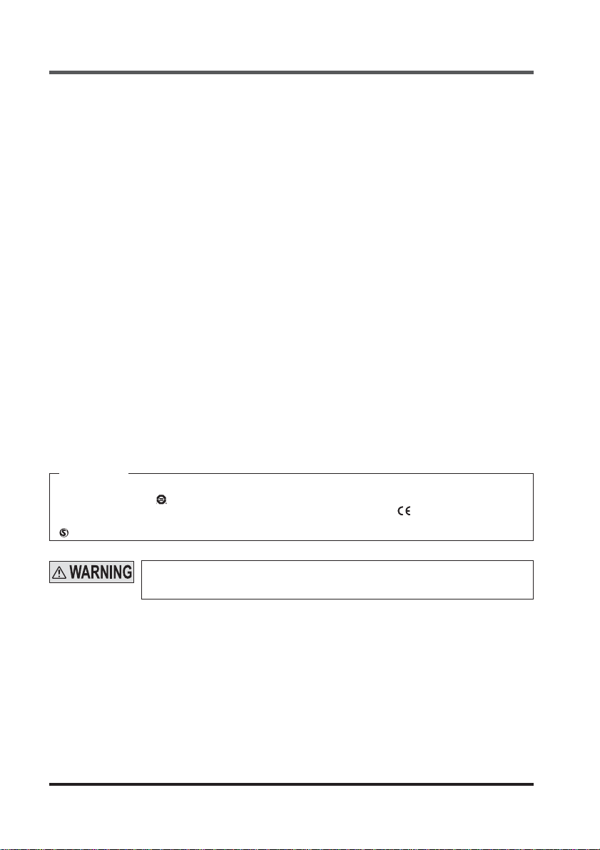
The C-TUV US Mark
This device conforms to the EMC Directive and the Machinery directive. The
cates that this device conforms to the EMC Directive.
mark marked on this device shows that this device has certifi ed with the type examination certifi cate.
indicates compliance with both CSA of Canada and US requirements.
mark on the product indi-
When this device is used in a place other than the places shown above, be sure
to confi rm the standards or regulations applicable in each region or country before
use.
1-4 Confi rmation of Packed Contents
□ Main device 1 unit
□ Instruction manual (this document) 1 pc.
□ Terminal blocks (6 poles) 2 pcs.
□ Terminal blocks (14 poles) 1 pc.
7
© Panasonic Electric Works SUNX Co., Ltd. 2010 MJE-SQ4C11 No.0017-23V
Before using this device
Chapter 2 Before using this device
2-1 Features
This device is the controller for safety liquid leak sensor with the following features:
● This device and safety liquid leak sensor SQ4-A series are combined for operation.
● Maximum of 4 safety liquid leak sensors can be connected to this device.
● With the output polarity selection switch of the controller, the control output 1 / 2 (OSSD 1 / 2)
can be switched to the PNP / NPN output. SQ4-A□-P PNP output type and SQ4-A□-N NPN
output type cannot be used together.
● Replacement of the relay is not required with the semi-conductor output.
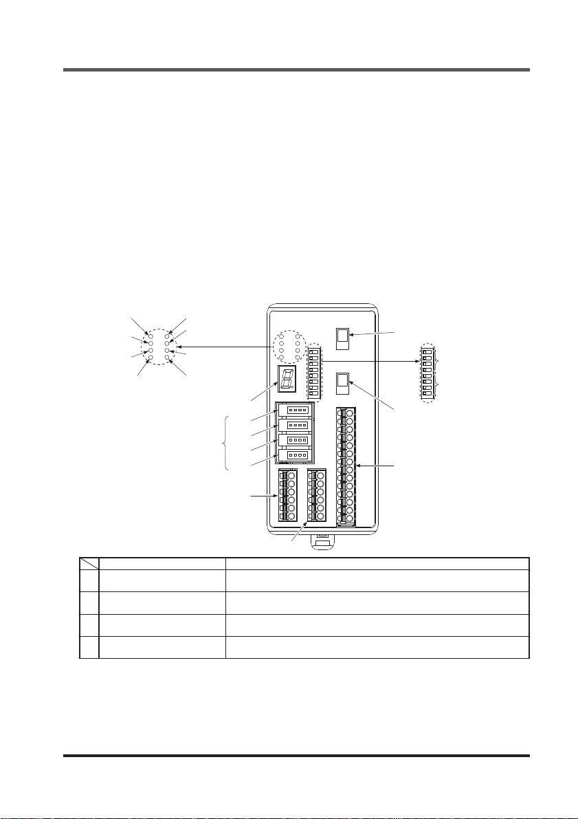
2-2 Names and Functions of Parts
1. OSSD output
indicator (Green)
2. OSSD output
indicator (Red)
3. Interlock
indicator (Yellow)
4. Test input
indicator (Orange)
9. Digital error indicator (Red)
10. Sensor connector
5.
Sensor monitor output
1 indicator (Orange)
6.
Sensor monitor output
2 indicator (Orange)
7.
Sensor monitor output
3 indicator (Orange)
8.
Sensor monitor output
4 indicator (Orange)
No. 1
No. 2
No. 3
No. 4
11. Control output polarity
selection switch
13. Safety input mode
setting switch
14.
Sensor connection
number setting switch
12. Non-safety output polarity
selection switch
15. I/O terminal block (14 poles)
17. Input terminal block (6 poles)
16. Input terminal (6 poles)
OSSD output indicator (Green)
1
[OSSD ON]
OSSD output indicator (Red)
2
[OSSD OFF]
Interlock indicator (Yellow)
3
[INLK]
Test input indicator (Orange)
4
[TEST]
Names Functions
Lights when control output 1/2 (OSSD1 / 2) is ON.
Lights when control output (OSSD 1 / 2) is OFF.
Lights for interlock goes OFF for an error or when control output 1 / 2
(OSSD 1 / 2) is ON.
Lights when test input terminal is open (effective).
© Panasonic Electric Works SUNX Co., Ltd. 2010 MJE-SQ4C11 No.0017-23V
8
Parts Description
Sensor monitor output 1 indicator
5
(Orange) [AUX1]
Sensor monitor output 2 indicator
6
(Orange) [AUX2]
Sensor monitor output 3 indicator
7
(Orange) [AUX3]
Sensor monitor output 4 indicator
8
(Orange) [AUX4]
9 Digital error indicator (Red)
10 Sensor connector
Control output polarity
11
selection switch
Non-safety output polarity
12
selection switch
Safety input mode setting switch
13
(Switch No. 1 to No. 4)
Sensor connection number
14
setting switch
(Switch No. 5 to No. 8)
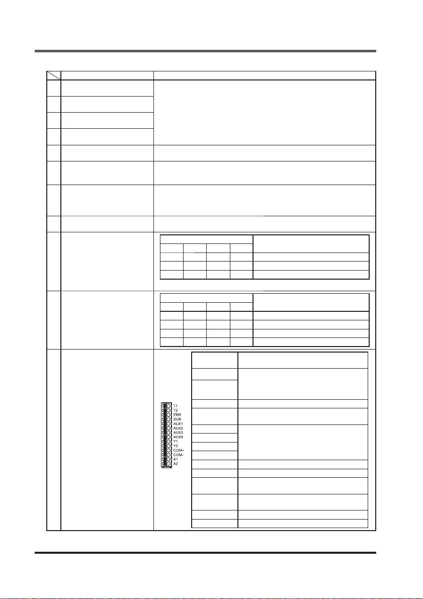
I/O terminal block
15
(14 poles)
Names Functions
Light up when auxiliary detection output of each sensor is ON.
Blink when sensor error is occurred. For details, refer to “Chapter 5 Trou-
bleshooting.”
It lights in 7 segments for an error.
For details, refer to “Chapter 5 Troubleshooting.”
Connect safety liquid leak sensor SQ4-A series. (Maximum 4)
To connect multiple sensors, use the connector from No. 1.
PNP output type and NPN output type cannot be used together.
The polarities of control output 1 / 2 (OSSD 1 / 2) are set to the PNP output
or the NPN output mode.
The polarities of safety input 1 / 2 are set to the PNP input or the NPN input
mode.
Polarities of non-safety output ERR, SUB, AUX1 to 4 are set to the PNP
output or the NPN output.
Switch No.
1234
ON OFF ON OFF Invalid
OFF ON OFF ON Valid: Semiconductor input mode
OFF OFF OFF OFF Valid: Contact input mode
Settings other than above become lockout status.
Switch No.
5678
ON ON ON ON 1 unit
ON OFF ON OFF 2 units
OFF ON OFF ON 3 units
OFF OFF OFF OFF 4 units
Terminal
names
ERR Lockout output
SUB
AUX1
AUX2
AUX3
AUX4
COM+
COM-
Test input terminal (for contact only)
T1
Open: Test input valid
[Control output 1 / 2 (OSSD 1 / 2) OFF]
T2
Short circuit: Test input invalid
Output for negative logic output of control
output 1 / 2 (OSSD 1 / 2)
Sensor monitor output 1 to 4
Monitor output corresponding to the detection auxiliary output of sensors No. 1 to 4
Y1 Control output 1 (OSSD 1)
Y2 Control output 2 (OSSD 2)
Common terminal for control output 1 / 2
(OSSD 1 / 2) return in NPN output
Common terminal for control output 1/2
(OSSD 1 / 2) return in PNP output
A1 +24V
A2 0V
Safety input 1 / 2
No. of connecting sensors
Description
9
© Panasonic Electric Works SUNX Co., Ltd. 2010 MJE-SQ4C11 No.0017-23V
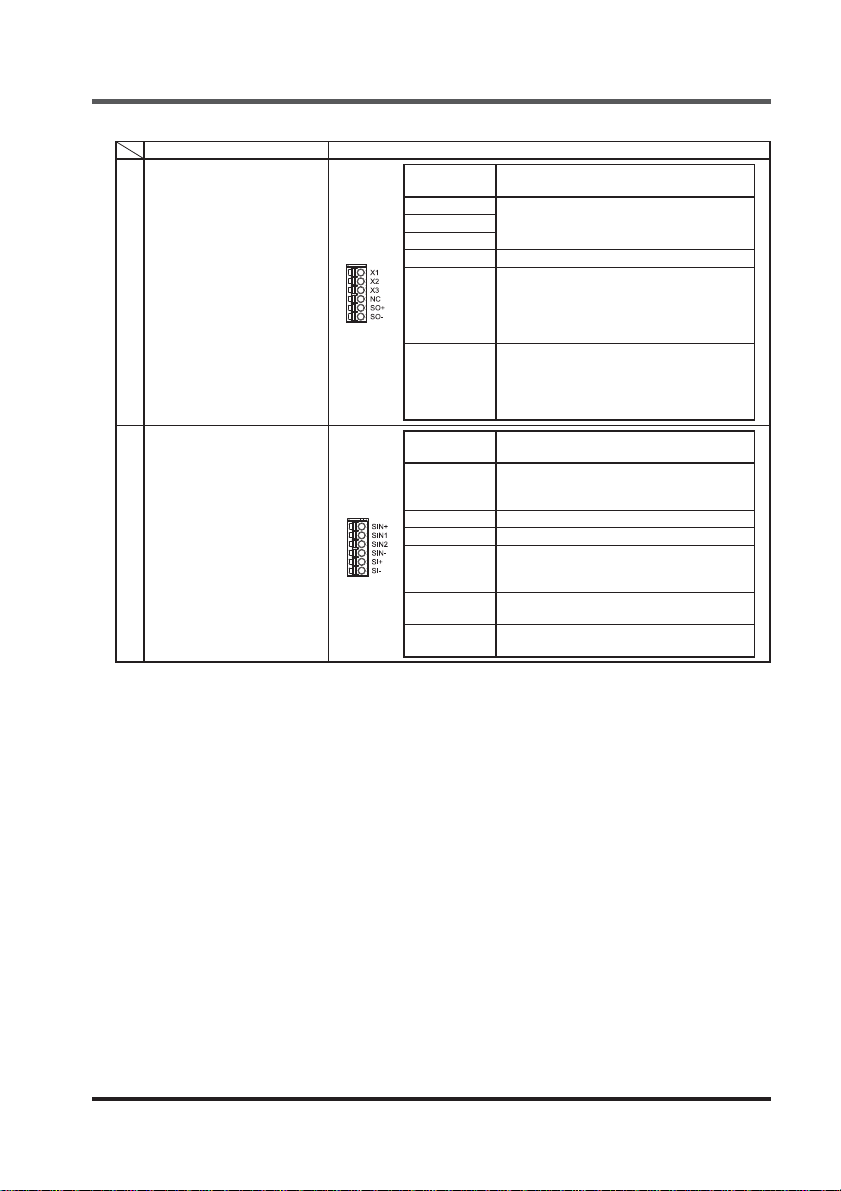
Names Functions
16 Input terminal block (6 poles)
17 Input terminal block (6 poles)
Terminal
names
X1
Reset input terminal
X1 - X2 connection: Manual reset
X2
X1 - X3 connection: Auto reset
X3
NC Not used
SO+
SO-
Terminal
names
SIN+
SIN1 Safety input 1
SIN2 Safety input 2
SIN-
SI+
SI-
When the safety input 1 / 2 is in contact
mode, it is connected to the SI+ terminal
for power supply.
When safety input mode is invalid and it is
in semiconductor input mode, not used.
When the safety input 1 / 2 is in contact
mode, it is connected to the SI- terminal for
power supply.
When safety input mode is invalid and it is
in semiconductor input mode, not used.
Common terminal when the safety input 1
/ 2 is the semiconductor input mode and in
the NPN output.
Common terminal when the safety input 1
/ 2 is the semiconductor input mode and in
the PNP output.
It is connected to the SO+ terminal when the
safety input
It is connected to the SO- terminal when the
safety input
Parts description
Description
Description
1 / 2
is in the contact mode.
1 / 2
is in the contact mode.
© Panasonic Electric Works SUNX Co., Ltd. 2010 MJE-SQ4C11 No.0017-23V
10
Mounting / Removal
2-3 Mounting / Removal
2-3-1 Mounting / Removal of Controller
The controller can be mounted on the 35mm width DIN rail.
<Mounting method>
Step 1 Fit the tab on the opposite side of the DIN rail stopper into the 35mm width DIN rail.
Step 2 Press down the tab on the other side against the 35mm width DIN rail to fi t it.
DIN rail stopper
1
2
3
35mm width DIN rail
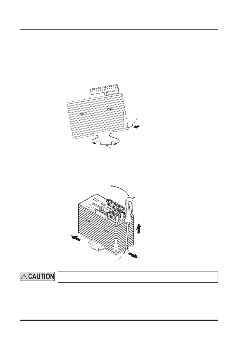
<Removing method>
Insert a fl athead screwdriver to the groove on the DIN rail stopper and pull out the stopper.
Step 1
Step 2 Push the controller to the other side of the DIN rail stopper.
Step 3 While maintaining the condition in the procedure 2, lift up the controller to remove it.
1
Flathead screwdriver
3
2
1
DIN rail stopper
Take care that if the controller is lifted with the stopper remained inside, the tabs
crack
11
© Panasonic Electric Works SUNX Co., Ltd. 2010 MJE-SQ4C11 No.0017-23V
 Loading...