

Panasonic SC-PM18, SC-PM18E User Manual
CD Stereo System
Operating Instructions
Model No. SC-PM18
E
EB GN
Note:
“EB” on the packaging indicates the United
Kingdom.
Before connecting, operating or adjusting this
product, please read these instructions completely.
Please keep this manual for future reference.
RQT6686-1B

Dear customer
Thank you for purchasing this product.
For optimum performance and safety, please read these
instructions carefully.
Table of contents
Before use
These operating instructions are applicable to the following
system.
System SC-PM18
Main unit SA-PM18
Speakers SB-PM18
Before use
Side of
product
Supplied accessories ................................................. 3
Safety precautions ...................................................... 3
Caution for AC Mains Lead ........................................ 4
The remote control ..................................................... 5
Placement of speakers ............................................... 5
Connections ................................................................ 6
Front panel controls ................................................... 8
Listening operations
The radio: manual tuning .......................................... 9
The radio: preset tuning ............................................ 11
CDs ............................................................................... 12
Cassette tapes ............................................................. 17
Recording operations
Before recording ......................................................... 18
Recording from the radio ........................................... 19
Recording CDs ............................................................ 20
Timers and others
Using the built-in sound quality settings ................. 21
Enhancing the sound quality ..................................... 21
Using an external unit ................................................ 21
Auto-off function ......................................................... 22
Turning the demo function off ................................... 22
Setting the time ........................................................... 23
Convenient functions ................................................. 23
Using the timers .......................................................... 24
Inside of product
Tuotteen sisällä
Produktets innside
Reference
Troubleshooting guide ............................................... 26
Specifications .............................................................. 27
Maintenance ................................................................ 27
When moving the unit ................................... Back cover
This product may receive radio interference caused by mobile telephones during use. If such interference is apparent,
please increase separation between the product and the
mobile telephone.
THIS UNIT IS INTENDED FOR USE IN MODERATE
CLIMATES.
TÄMÄ LAITE ON TARKOITETTU KÄYTETTÄVÄKSI
LEUDOSSA ILMASTOSSA.
DETTE APPARATET ER BEREGNET TIL BRUK
UNDER MODERATE KLIMAFORHOLD.
2
RQT6686

Supplied accessories
Safety precautions
Please check and identify the supplied
accessories.
Use numbers indicated in parentheses
when asking for replacement parts.
AC mains lead . . . . . . . . . . . . . . . . . . . . . . . 1 pc.
For the United Kingdom
(VJA0733)
For Continental Europe
(RJA0019-2K)
AM loop antenna . . . . . . . . . . . . . . . . . . . . 1 pc.
(RSA0033A-1)
FM indoor antenna . . . . . . . . . . . . . . . . . . . .1 pc.
For Europe For Others
(RSA0007-L) (RSA0006-L)
For Australia
and N.Z.
(RJA0035-X)
Placement
Set the unit up on an even surface away from direct
sunlight, high temperatures, high humidity, and excessive
vibration. These conditions can damage the cabinet and
other components, thereby shortening the unit’s service life.
Place it at least 15 cm away from wall surfaces to avoid
distortion and unwanted acoustical effects.
Do not place heavy items on the unit.
Voltage
Do not use high voltage power sources. This can
overload the unit and cause a fire.
Do not use a DC power source. Check the source
carefully when setting the unit up on a ship or other place
where DC is used.
AC mains lead protection
Ensure the AC mains lead is connected correctly and not
damaged. Poor connection and lead damage can cause fire
or electric shock. Do not pull, bend, or place heavy items on
the lead.
Grasp the plug firmly when unplugging the lead. Pulling
the AC mains lead can cause electric shock.
Do not handle the plug with wet hands. This can cause
electric shock.
Foreign matter
Do not let metal objects fall inside the unit. This can cause
electric shock or malfunction.
Do not let liquids get into the unit. This can cause electric
shock or malfunction. If this occurs, immediately disconnect
the unit from the power supply and contact your dealer.
Do not spray insecticides onto or into the unit. They
contain flammable gases which can ignite if sprayed into the
unit.
Before use
Remote control transmitter . . . . . . . . . . . . . 1 pc.
(EUR7711020)
Remote control batteries . . . . . . . . . . . . . . 2 pcs.
R6, AA, UM-3
Antenna plug adaptor . . . . . . . . . . . . . . . . . 1 pc.
For the United Kingdom only
(SJP9009)
Service
Do not attempt to repair this unit by yourself. If sound is
interrupted, indicators fail to light, smoke appears, or any
other problem that is not covered in these instructions
occurs, disconnect the AC mains lead and contact your
dealer or an authorized service center. Electric shock or
damage to the unit can occur if the unit is repaired,
disassembled or reconstructed by unqualified persons.
Extend operating life by disconnecting the unit from the
power source if it is not to be used for a long time.
For the United Kingdom and Republic of Ireland
shop@
www.panasonic.co.uk (for UK customers only)
• Order accessory and consumable items for your product with
ease and confidence by telephoning our Customer Care Centre
Mon–Friday 9:00 am–5:30 pm.
(Excluding public holidays.)
• Or go on line through our Internet Accessor y ordering application.
• Most major credit and debit cards accepted.
• All enquiries transactions and distribution facilities are provided
directly by Panasonic UK Ltd.
• It couldn’t be simpler!
Customer Care Centre
For UK customers: 08705 357357
For Republic of Ireland customers: 01 289 8333
Technical Support
For UK customers: 0870 1 505610
This Technical Support Hot Line number is for Panasonic PC
software related products only.
For Republic of Ireland, please use the Customer Care Centre
number listed above for all enquiries.
For all other product related enquiries, please use the
Customer Care Centre numbers listed above.
3
RQT6686
Caution for AC Mains Lead
(For United Kingdom)
(“EB” area code model only)
For your safety, please read the following text
carefully.
This appliance is supplied with a moulded
three pin mains plug for your safety and
convenience.
A 5-ampere fuse is fitted in this plug.
Before use
Should the fuse need to be replaced please
ensure that the replacement fuse has a rating
of 5-ampere and that it is approved by ASTA or
BSI to BS1362.
Check for the ASTA mark m or the BSI mark
o on the body of the fuse.
If the plug contains a removable fuse cover you
must ensure that it is refitted when the fuse is
replaced.
If you lose the fuse cover the plug must not be
used until a replacement cover is obtained.
A replacement fuse cover can be purchased
from your local dealer.
WARNING: DO NOT CONNECT EITHER
WIRE TO THE EARTH TERMINAL WHICH IS
MARKED WITH THE LETTER E, BY THE
EARTH SYMBOL
GREEN OR GREEN/YELLOW.
THIS PLUG IS NOT WATERPROOF—KEEP
DRY.
nn
n OR COLOURED
nn
Before use
Remove the connector cover.
How to replace the fuse
The location of the fuse differ according to the
type of AC mains plug (figures A and B).
Confirm the AC mains plug fitted and follow the
instructions below.
Illustrations may differ from actual AC mains
plug.
1. Open the fuse cover with a screwdriver.
Figure A
4
RQT6686
CAUTION!
IF THE FITTED MOULDED PLUG IS
UNSUITABLE FOR THE SOCKET
OUTLET IN YOUR HOME THEN THE
FUSE SHOULD BE REMOVED AND THE
PLUG CUT OFF AND DISPOSED OF
SAFELY.
THERE IS A DANGER OF SEVERE
ELECTRICAL SHOCK IF THE CUT OFF
PLUG IS INSERTED INTO ANY 13-AMPERE SOCKET.
If a new plug is to be fitted please observe the
wiring code as stated below.
If in any doubt please consult a qualified
electrician.
IMPORTANT
The wires in this mains lead are coloured in
accordance with the following code:
Blue: Neutral, Brown: Live.
As these colours may not correspond with the
coloured markings identifying the terminals in
your plug, proceed as follows:
The wire which is coloured Blue must be
connected to the terminal which is marked with
the letter N or coloured Black or Blue.
The wire which is coloured Brown must be
connected to the terminal which is marked with
the letter L or coloured Brown or Red.
Figure B
2. Replace the fuse and close or attach the
fuse cover.
Figure A
Figure B
Fuse cover
Fuse
(5 ampere)
Fuse
(5 ampere)

A
The remote control
B
Remote control
signal sensor
Transmission
window
R6, AA, UM-3
About 7 meters in
front of the signal
sensor.
A Battery installation
Use of batteries
• Align the poles (+ and –) properly when inserting the
batteries.
• Do not mix old and new batteries or different types of
batteries.
• Do not recharge ordinary dry cell batteries.
• Do not heat or disassemble the batteries. Do not allow
them to contact flame or water.
• Remove the batteries if the unit is not to be used for a long
time.
• Do not keep together with metallic objects such as
necklaces.
• Do not use rechargeable type batteries.
• Do not use batteries if the covering has been peeled off.
Mishandling of batteries can cause electrolyte leakage
which can damage items the fluid contacts and may cause a
fire.
If electrolyte leaks from the batteries, consult your dealer.
Wash thoroughly with water if electrolyte comes in contact
with any part of your body.
B Correct method of use
Operation notes
• Do not place obstacles between the remote control signal
sensor and remote control unit.
• Do not expose the remote control signal sensor to direct
sunlight or to the bright light of a fluorescent light.
• Take care to keep the remote control signal sensor and
the end of the remote control unit free from dust.
• If this system is installed in a rack with glass doors, the
glass doors’ thickness or color might make it necessary to
use the remote control unit a shorter distance from the
system.
Before use
C
To prevent damage
• Do not place heavy items on the remote control.
• Do not disassemble or reconstruct.
• Do not spill water or other liquids on the remote control.
C
Placement of speakers
Speakers are designed identically so that no left or right
channel orientation is necessary.
Notes
• Keep your speakers at least 10 mm away from the system
for proper ventilation.
• These speakers do not have magnetic shielding. Do not
place them near televisions, personal computers or other
devices easily influenced by magnetism.
• To avoid damage to the speakers, do not touch the
speaker cones if you have taken the nets off.
5
RQT6686
Before use
R
L
LOW (6
)
HIGH (6
)
Appliance inlet
Connector
Approx. 3.5 mm
1
2
AM loop antenna
For Europe
For Europe
1
(R)
Connections
• Plug the AC mains lead into a household mains socket
only after all other connections have been made.
1
2
(L)
• To prepare the AM loop antenna wire and speaker cords,
twist the vinyl cover tip and pull off.
3
1 Connect the FM indoor antenna.
Tape the antenna to a wall or column, in a position
To household
mains socket
4
For Others
Adhesive
tape
FM indoor
antenna
1
2
For Others
1
2
2
where radio signals are received with the least amount
of interference.
Note
For the best reception:
An FM outdoor antenna is recommended. (\ page 7)
2 Connect the AM loop antenna.
Stand the antenna up on its base. Keep loose antenna
cord away from other wires and cords.
3 Connect the speaker cables.
A Confirm the colors of the tags on the ends of the
cords.
B For White tags:
Connect cords to grey terminals.
For Blue, Black and Red tags:
Connect cords so tag colors match the terminal
colors.
Cords with white and blue tags are for high frequency.
Cords with red and black tags are for low frequency.
Incorrect connection can damage the unit.
Caution
Use only the supplied speakers.
The combination of the main unit and speakers provide
the best sound. Using other speakers can damage the
unit and sound quality will be negatively affected.
Caution
• Use the speakers only with the recommended
system.
Failure to do so may lead to damage to the
amplifier and/or the speakers, and may result
in the risk of fire. Consult a qualified service
person if damage has occurred or if you
experience a sudden change in performance.
• Do not attach these speakers to walls or
ceilings.
6
RQT6686
3
B
Grey (+)
Red (+)
A
4 Connect the AC mains lead.
White
Blue
Black
Red
1
3
2
FOR THE UNITED KINGDOM ONLY
READ THE CAUTION FOR THE AC MAINS
LEAD ON PAGE 4 BEFORE CONNECTION.
Insertion of Connector
Even when the connector is perfectly inserted,
depending on the type of inlet used, the front part of the
connector may jut out as shown in the drawing.
However there is no problem using the unit.
Note
The included AC mains lead is for use with this unit
only. Do not use it with other equipment.
A
1
B
For Europe
For Europe
For Others
FM outdoor antenna
(not included)
(Only for United Kingdom)
FM outdoor antenna
(not included)
2
AM outdoor antenna
(not included)
5-12m
AM loop antenna
(included)
Use the antenna
plug adaptor
(included).
Shield braid
Core wire
Connections
Optional antenna connections
You may need an outdoor antenna if you use this system in
a mountainous region or inside a reinforced-concrete
building, etc.
FM outdoor antenna
A
Disconnect the FM indoor antenna if an FM outdoor
antenna is installed.
Note
An outdoor antenna should be installed by a qualified
technician only.
AM outdoor antenna
B
Connect the outdoor antenna without removing the AM loop
antenna. Run 5 to 12 m of vinyl-covered wire horizontally
along a window or other convenient location.
Note
When the unit is not in use, disconnect the outdoor antenna
to prevent possible damage that may be caused by
lightning. Never use an outdoor antenna during an electrical
storm.
External unit connections
• Make sure that the power supply for all components has
been turned off before making any connections.
• For details, refer to the operating instructions of the unit
which is to be connected.
• All peripheral components and cables sold separately.
Before use
For Others
AM outdoor antenna
(not included)
C
"LINE OUT"
position
Analogue player (not included)
5-12m
AM loop antenna
(included)
(R)
(L)
AUX
Rear panel of this unit
Connecting analogue equipment
C
This example shows how to connect an analogue player
with a PHONO OUT/LINE OUT switch.
When units other than those described are to be connected,
please consult your audio dealer.
Note
• Only an analogue player with a built-in phono equalizer
can be connected.
• Set the switch to the “LINE OUT” position at the back of
the analogue player.
L
R
7
RQT6686

Before use
3
4
5
6
7
8
1
OPEN
AC IN
2
9
!
AUX REC
S.SOUND EQ
FF
STOP
DEMO
REW
CD 1 CD 2 CD 3 CD 4 CD 5
CD CHECK
TUNER BANDCDTAPE
VOLUME
DOWN
UP
OPEN/CLOSE
CD CHANGE
"
#
$
%
&
PHONES
(
)~+,
Front panel controls
Main unit
Cassette lid
1
2
Cassette open button (c OPEN) ............................ 17
3
AC supply indicator (AC IN)
This indicator lights when the unit is connected to the AC
mains supply.
4
Standby/on switch ( )
Press to switch the unit from on to standby mode or vice
versa. In standby mode, the unit is still consuming a
small amount of power.
5
Aux button (AUX) ..................................................... 21
6
CD skip/search, tape fast-forward/rewind/TPS, tune/
preset channel select, time adjust buttons
33
(f
3 /FF, g
33
7
CD check button (CD CHECK) ................................ 13
8
CD trays
9
Tape indicator
This indicator changes in the following manner:
a
Orange (when no cassette is inserted.)
b
Green (when cassette is inserted.)
c
Red (when in recording mode.)
Ä
Display
Å
Recording start/pause button ([/ J REC) .............. 19
Ç
Super sound EQ button (S.SOUND EQ) ................. 21
É
Volume control (VOLUME DOWN, UP) ......... 9, 12, 17
Ñ
CD tray open/close button (c OPEN/CLOSE) ....... 12
Ö
CD change button (c CD CHANGE) ....................... 13
Ü
Headphone jack (PHONES) ..................................... 21
á
Stop/program clear and demonstration button
(STOP L, –DEMO) .................................. 12, 16, 17, 22
à
Tuner/band select button (TUNER/BAND) ............. 10
â
Cassette play button (TAPE -) .............................. 17
ä
CD play/pause button (CD -/ J) ............................. 12
ã
Disc direct play buttons (CD 1~CD 5) .................... 12
44
4/REW) .............. 9, 11, 12, 16, 18, 23
44
8
RQT6686
STOP
DEMO
CD 1 CD 2 CD 3 CD 4 CD 5
TUNER BANDCDTAP E
-
CLOCK
TIMER
REC
DISC
PLA
Y MODE
REW
S.SOUND EQ
DIMMER
DISPLAYPRESET EQ
PRESET EQ
FF
PGM
VOL
VOL
CD
AUX
TUNER/
BAND
APE
CLEAR
4
CLOCK
TIMER
REC
UTO OFF
DISC
PLA
Y MODE
MUTING
REW
S.SOUND EQ
DIMMER
DISPLAYPRESET EQ
PRESET EQ
FF
PGM
VOL
VOL
CD
AUX
TUNER/
BAND
APE
CLEAR
.
/
:
;
~
5
<
#
=
DISC
PLA
Y MODE
TUNER/
BAND
MUTING
S.SOUND EQ
AUTO OFF
VOL
SLEEP
1
4
7
PGM
CD
CLEAR
AUX
PLPLAY
CLOCK
REC
TIMER
23
65
89
10
0
TAPE
VOL
FF
REW
DIMMER
DISPLA
>
?
@
,
+
[
$
6
\
]
Front panel controls
Remote Control
Buttons such as 4 function in exactly same way as the
buttons on the main unit.
å
Sleep timer/auto off button
(SLEEP, –AUTO OFF) ........................................ 22, 25
ç
Disc button (DISC) ................................................... 14
é
Play mode select button
(PLAY MODE) ......................................... 10, 14, 15, 19
Use this for selecting repeat mode, CD play mode, tune
mode, FM mode, AM beat proof function.
è
CD Program/clear, tuner preset button
(PGM) .................................................................. 11, 16
ê
Muting button (MUTING) ........................................ 23
ë
Preset EQ select button (PRESET EQ) ................. 21
í
Play timer/recording timer button
˚˚
(
˚PLAY/REC) ........................................................... 24
˚˚
ì
Clock/timer button (CLOCK/TIMER) ........... 23, 24, 25
î
Numeric buttons ( 10, 1–9, 0) ........................... 11, 15
ï
Stop/program clear button (L CLEAR) ..... 12, 16, 17
ñ
Dimmer button (DIMMER) ....................................... 23
ó
Display button (DISPLAY) ................................. 10, 15
Before use
Before use
Listening operations
1
2
3
2
DISC
PLA
Y MODE
TUNER/
MUTING
S.SOUND EQ
TUNER BAND
PLAY MODE
REW
3
PLPLAY
CLOCK
SLEEP
REC
AUTO OFF
TIMER
23
1
65
4
89
7
10
PGM
0
CD
CLEAR
TAPE
BAND
AUX
VOL
VOL
FF
REW
DIMMER
DISPLA
1
4
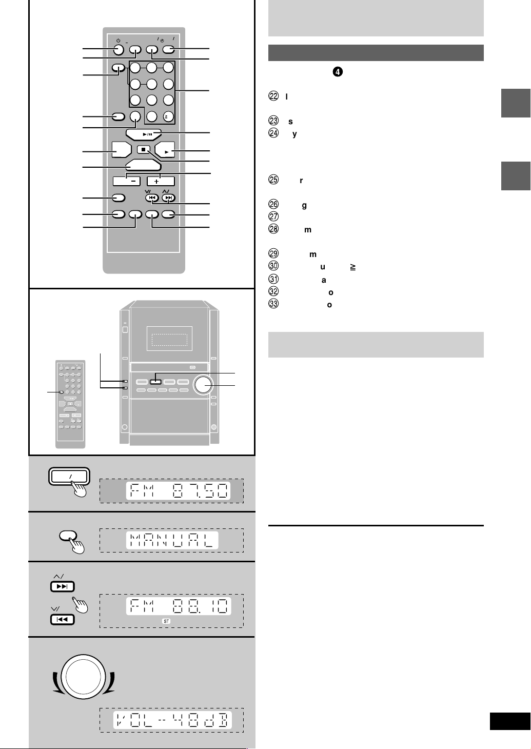
The radio: manual tuning
1 Press [TUNER/BAND] to select “FM” or “AM”.
The unit comes on automatically.
Every time you press the button:
FM ↔ AM
2 Press [PLAY MODE] on the remote control to
select “MANUAL”.
Every time you press the button:
MANUAL ↔ PRESET
3 Press [g
44
4/REW] or [f
44
33
3 /FF] to select
33
the frequency of the required station.
“ST” is displayed when a stereo FM broadcast is being
received.
4 Adjust the volume.
Auto tuning
Press and hold [g
until the frequency starts changing rapidly. The unit begins
FF
auto tuning, stopping when it finds a station.
• Auto tuning may not function when there is excessive
interference.
• To cancel auto tuning, press [g
once again.
44
4/REW] or [f
44
44
4/REW] or [f
44
33
3 /FF] for a moment
33
33
3 /FF]
33
4
VOLUME
DOWN
UP
9
RQT6686
 Loading...