

Panasonic SC-HT40 User Manual
Operating Instructions
For Canada only: The word "Participant" is used in
place of the word "Partner".
1
1
Table of contents
Home Theater Audio System
Model No. SC-HT40
Dear customer
Thank you for purchasing this product.
Please read these instructions carefully before connecting,
operating or adjusting this product.
Please keep this manual for future reference.
If you have any questions, contact 1-800-211-PANA (7262)
in the U.S.A. or 1-800-561-5505 in Canada.
P
PC
Before use
IMPORTANT SAFETY INSTRUCTIONS .........2
Supplied accessories ....................................3
Listening caution ...........................................3
The remote control .........................................3
Step 1
Step 2
Speaker setup
4
Home theater
connections
6
Step 3
Antenna and AC power
supply connections
7
Step 4
Settings
8
Operations
Basic operations ..........................................10
Control guide ................................................11
Making a recording ......................................13
The RESET function .....................................13
MENU operation ...........................................14
The radio ....................................................... 15
Sound field ....................................................
Other functions ............................................17
Other settings ...............................................18
Remote control operation guide .................19
Product service ............................................20
16
Reference
Specifications ...............................................
Warranty (U.S.A.) ..........................................22
Warranty (Canada) .......................................23
Troubleshooting guide .................Back cover
Maintenance ..................................Back cover
21
RQTV0105-2P
IMPORTANT SAFETY INSTRUCTIONS
Read these operating instructions carefully before using the unit. Follow the safety instructions on the unit and the applicable safety
instructions listed below. Keep these operating instructions handy for future reference.
1) Read these instructions.
2) Keep these instructions.
10) Protect the power cord from being walked on or pinched
particularly at plugs, convenience receptacles, and the
point where they exit from the apparatus.
3) Heed all warnings.
4) Follow all instructions.
5) Do not use this apparatus near water.
6) Clean only with dry cloth.
7) Do not block any ventilation openings. Install in accordance
with the manufacturer’s instructions.
8) Do not install near any heat sources such as radiators, heat
registers, stoves, or other apparatus (including amplifiers)
that produce heat.
9) Do not defeat t he safety purpose o f the po la rized or
grounding-type plug. A polarized plug has two blades with
one wider than the other. A grounding-type plug has two
blades and a third grounding prong. The wide blade or the
third prong are provided for your safety. If the provided
IMPORTANT SAFETY INSTRUCTIONS
plug does not fit into your outlet, consult an electrician for
replacement of the obsolete outlet.
CAUTION
RISK OF ELECTRIC SHOCK
DO NOT OPEN
CAUTION: TO REDUCE THE RISK OF ELECTRIC
SHOCK, DO NOT REMOVE SCREWS.
NO USER-SERVICEABLE PARTS
INSIDE.
REFER SERVICING TO QUALIFIED
SERVICE PERSONNEL.
The lightning flash with arrowhead symbol,
within an equilateral triangle, is intended
to a l e r t th e us e r to th e pr e s e n c e of
uninsulated “dangerous voltage” within the
product's enclosure that may be of sufficient
magnitude to constitute a risk of electric
shock to persons.
The exclamation point within an equilateral
triangle is intended to a le rt the us er to
the presence of important operating and
maintenance (servicing) instructions in the
literature accompanying the appliance.
WARNING:
TO REDUCE THE RISK OF FIRE, ELECTRIC SHOCK
OR PRODUCT DAMAGE, DO NOT EXPOSE THIS
APPARATUS TO RAIN, MOISTURE, DRIPPING OR
SPLASHING AND THAT NO OBJECTS FILLED WITH
LIQUIDS, SUCH AS VASES, SHALL BE PLACED ON
THE APPARATUS.
RQTV0105
The socket outlet shall be installed near the equipment and
easily accessible or the mains plug or an appliance coupler
2
shall remain readily operable.
11) On ly use att ach men ts/ acc essor ies spe cif ied b y t he
manufacturer.
12) Us e onl y with the c ar t, stand , tri pod,
br a c k e t , o r ta bl e spe c i f i e d b y th e
manufacturer, or sold with the apparatus.
When a cart is used, use caution when
moving the cart/apparatus combination to
avoid injury from tip-over.
13) Unplug this apparatus during lightning storms or when
unused for long periods of time.
14) Refer all servicing to qualified service personnel. Servicing
is required when the apparatus has been damaged in any
way, such as power-supply cord or plug is damaged, liquid
has been spilled or objects have fallen into the apparatus,
the apparatus has been exposed to rain or moisture, does
not operate normally, or has been dropped.
THE FOLLOWING APPLIES ONLY IN THE U.S.A.
FCC Note:
This equipment has been tested and found to comply with the
limits for a Class B digital device, pursuant to Part 15 of the
FCC Rules.
These limits are designed to provide reasonable protection
against harmful interference in a residential installation. This
equipment generates, uses and can radiate radio frequency
energy and, if not installed and used in acc ordance with
the instructions, may cause harmful interference to radio
co mmu nicat ion s. How eve r, the re is no gua rante e t ha t
interference will not occur in a particular installation. If this
equipm en t doe s cause harmf ul int er fe rence to radio or
television reception, which can be determined by turning the
equipment off and on, the user is encouraged to try to correct
the interference by one or more of the following measures:
Reorient or relocate the receiving antenna.
•
In cr ease the sep ar ation b et ween the equ ipment and
•
receiver.
Connect the equipment into an outlet on a circuit different
•
from that to which the receiver is connected.
Consult the dealer or an experienced radio/TV technician
•
for help.
Any unauthorized changes or modifications to this equipment
would void the user’s authority to operate this device.
This device complies with Part 15 of the FCC Rules. Operation
is subject to the following two conditions: (1) This device
may not cause harmful interference, and (2) this device must
accept any interference received, including interference that
may cause undesired operation.
Responsible Party:
Panasonic Corporation of North America
One Panasonic Way
Secaucus, NJ 07094
Telephone No.: 1-800-211-7262
3
RQTV0105
System SC-HT40
(K2CB2CB00018)
(N2QAYB000009)
(RSA0007-L)
(N1DAAAA00002)
(RQCAV0006)
3
2
2
1
VOLUME
TV/VIDEO
MUTIN
G
VOLUME
SUBWOOFER
1
2 3
708
9
10
4 5
6
>
=
^
AV
SYSTEM
RECEIVER
DVR/DVD-P
TUNER
BAND
TV
TV
^
POWER
INPUT SELECTOR
TUNE
MENU
RETURN
SETUP
MUSIC PORT
VOLUME
ENTER
SURROUND
MUSIC
EST. 192 4
AV Control Receiver SA-HT40
Front speakers SB-PF40
Surround speakers SB-PS40
Center speaker SB-PC40
Subwoofer SB-W40
Supplied accessories
Please check and identify the supplied accessories.
CAUTION!
DO NOT INSTALL OR PLACE THIS UNIT IN A BOOKCASE,
BUILT-IN CABINET OR IN ANOTHER CONFINED SPACE.
ENSURE THE UNIT IS WELL VENTILATED. TO PREVENT
RI SK OF E LECTR IC S HOCK OR FIR E HAZAR D DUE
TO O VER HEATI NG, E NSU RE THA T CUR TAINS AN D
AN Y O THE R M ATE RIA LS DO N OT OBST RUC T T HE
VENTILATION VENTS.
CAUTION!
Do not place anything on top of this unit or block the heat
radiation vents in any way. In particular, do not place tape
decks or CD/DVD players on this unit as heat radiated from it
can damage your software.
1 AC power supply cord
1 FM indoor antenna
1 AM loop antenna 1 Remote control
2 Batteries 1 speaker sticker sheet
Use the numbers indicated in parentheses when asking for
replacement parts. (As of January 2006)
In the U.S.A. : To order accessories, refer to “Accessory
Purchases” on page 22.
In Canada : To order acce ssories, call the de aler from
whom you have made your purchase.
Listening caution
Selecting fine audio equipment such as the unit you’ve just
purchased is only the start of your musical enjoyment. Now it’s
time to consider how you can maximize the fun and excitement
your equipment offers. This manufacturer and the Electronic
Industries Association’s Consumer Electronics Group want you
to get the most out of your equipment by playing it at a safe
level. One that lets the sound come through loud and clear
without annoying blaring or distortion-and, most importantly,
without affecting your sensitive hearing.
If you see this symbol-
Information on Disposal in other Countries outside the
European Union
This symbol is only valid in the European Union.
If you wish to discard this product, please contact
your local authorities or dealer and ask for the correct
method of disposal.
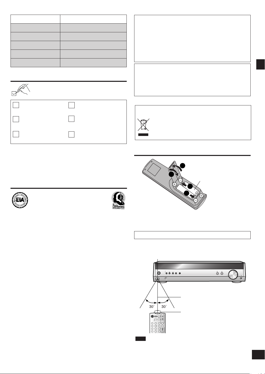
The remote control
R6/LR6, AA, UM-3
Ins ert so the poles (+ and -) match those in the remote
•
control.
Do not use rechargeable type batteries.
•
Use
Aim at the sensor, avoiding obstacles, at a maximum range of
7 m (23 feet) directly in front of the unit.
Remote control signal sensor
Supplied accessories/Listening caution/The remote control
We recommend that you avoid prolonged exposure to excessive
noise.
Sound can be deceiving. Over time your hearing “comfort level”
adapts to higher volumes of sound. So what sounds “normal”
can actually be loud and harmful to your hearing.
Guard against this by setting your equipment at a safe level
BEFORE your hearing adapts.
To establish a safe level:
Start your volume control at a low setting.
•
Slowly increase the sound until you can hear it comfortably
•
and clearly, and without distortion.
Once you have established a comfortable sound level:
•
Set the dial and leave it there.
Taking a minute to do this now will help to prevent hearing
damage or loss in the future. After all, we want you listening for
a lifetime.
7 meters (23 feet)
Transmission window
Note
•
Keep the transmission window and the unit's sensor free from
dust.
Operation can be affected by strong light sources, such as
•
direct sunlight, and the glass doors on cabinets.
2
1
2
3
4
5
6
1
FRONT
L
FRONT
L
FRONT
R
FRONT
R
SURROUND
L
SURROUND
L
SURROUND
R
SURROUND
R
C
(center)
1
FRONT
L
FRONT
L
2
FRONT
R
FRONT
R
SURROUND
L
SURROUND
L
SURROUND
R
SURROUND
R
C
(center)
C
(center)
C
(center)
SUB
(subwoofer)
SUB
(subwoofer)
SUB
(subwoofer)
SUB
(subwoofer)
3344556
6
1
2 3 4 5 6
1
2
3
45612
Step
1
1
2
3
4
5
6
FRONT
L
FRONT
L
FRONT
R
FRONT
R
SURROUND
L
SURROUND
L
SURROUND
R
SURROUND
R
C
(center)
1
FRONT
L
FRONT
L
2
FRONT
R
FRONT
R
SURROUND
L
SURROUND
L
SURROUND
R
SURROUND
R
C
(center)
C
(center)
C
(center)
SUB
(subwoofer)
SUB
(subwoofer)
SUB
(subwoofer)
SUB
(subwoofer)
3344556
6
1
2 3 4 5 6
1
2
3
456
1
2
FRONT
L
FRONT
L
1
1
FRONT
L
1
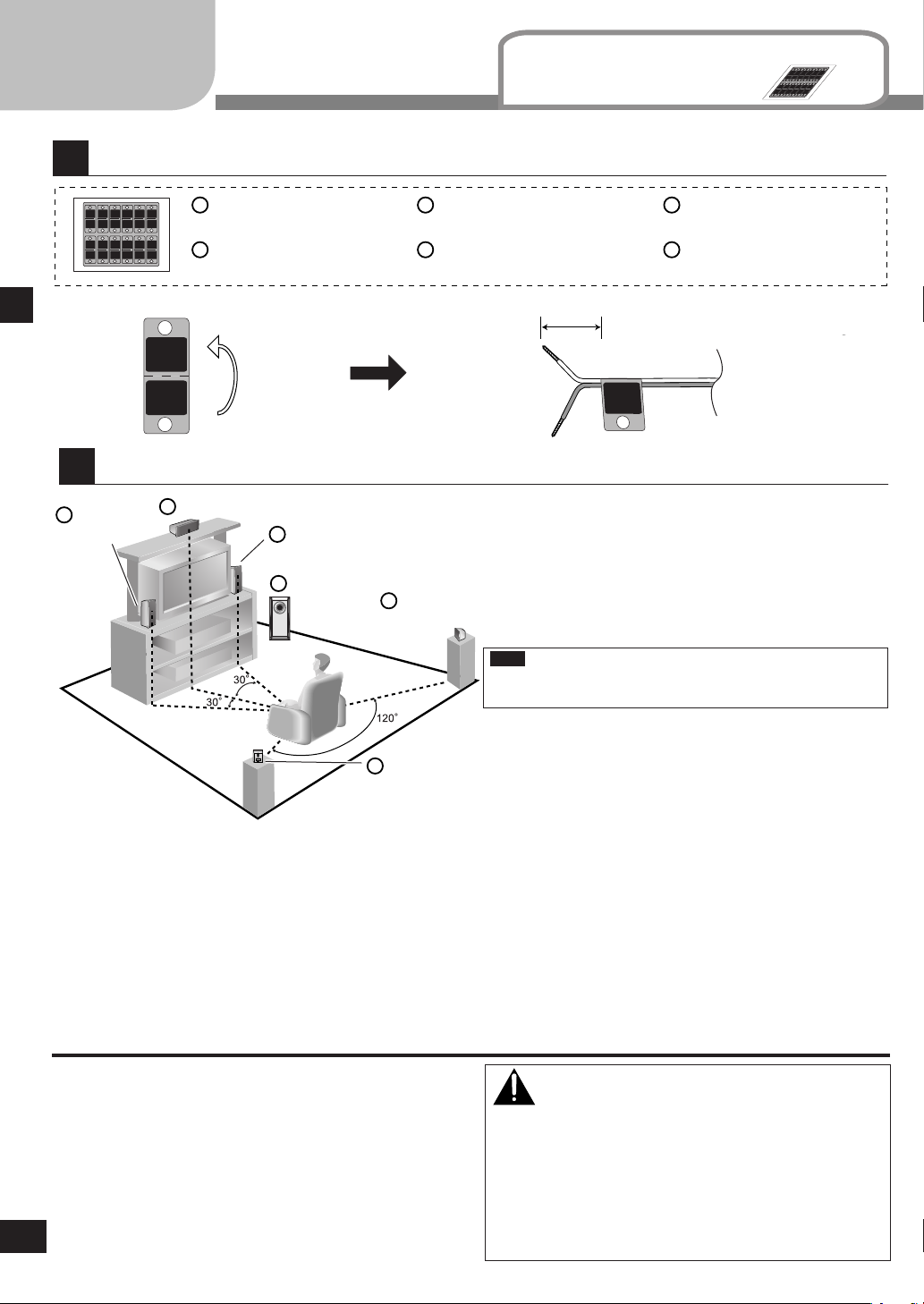
Speaker setup
Attach the stickers to the speaker cables.
Supplied
Sticker sheet
accessories
Step 1
Speaker setup
Placement of speakers.
Front
speaker (L)
Front speaker (L)
(SB-PF40)
Front speaker (R)
(SB-PF40)
Center speaker
Front speaker (R)
Subwoofer
Surround speaker (L)
(SB-PS40)
Surround speaker (R)
(SB-PS40)
Positioning for best effect
How you set up your speakers can affect the bass and the
sound field.
Note the following points.
•
Surround
•
speaker (R)
Center speaker
(SB-PC40)
Subwoofer
(SB-W40)
About 10 cm (4")
Place speakers on flat secure bases.
Placing speakers too close to floors, walls, and corners can
result in excessive bass. Cover walls and windows with a
thick curtain.
Note
Keep your speakers at least 10 mm (
13
/32") away from the
system for proper ventilation.
Surround
speaker (L)
Place the front, center, and surround speakers at approximately the same distance from the seating position.
The angles in the diagram are approximate.
Front speakers (left, right)
Place on the left and right of the TV at seated ear height so that there is good coherency between the picture and sound.
Center speaker
Place underneath or above the center of the TV. Aim the speaker at the seating area.
Surround speakers (left, right)
Place on the side of or slightly behind the seating area, higher than ear level.
Subwoofer
The subwoofer can be placed in any position as long as it is at a reasonable distance from the TV.
Note that some experimentation can yield the smoothest low frequency performance. Placement near a corner can increase the
apparent output level, but can result in unnatural bass.
If irregular coloring occurs on your television
The supplied speakers are designed to be used close to a
television, but the picture may be affected with some televisions
and setup combinations.
If this occurs, turn the television off for about 30 minutes.
The television's demagnetizing function should correct the
problem. If it persists, move the speakers further away from the
television.
RQTV0105
4
Caution
The main unit and supplied speakers are only to be
•
used as indicated in this manual. Failure to do so may
lead to damage to the receiver and/or the speakers, and
may result in the risk or fire. Consult a qualified service
person if damage has occurred or if you experience a
sudden change in performance.
Do not attempt to attach these speakers to walls using
•
methods other than those described in this manual.
5
RQTV0105
SUB
SPEAKERS (HAUT-PARLEURS)
R
C SURROUND FRONT
R L L
6Ω 4Ω
6 5 4 3 2 1
CENTER
SURROUND
L
SURROUND R
SUBWOOFER
FRONT R
FRONT L
3
FRONT
L
1
FRONT
R
SURROUND
L
SURROUND
R
C
(center)
SUB
(subwoofer)
2
34
5
6
Connect the speakers to the receiver.
7.5 - 9.4 mm
3.0 - 4.0 mm
FM
ANT
AM
ANT
75 Ω
LOOP
EXT
TV
AUDIO
LOOP
ANT
GND
DVR/DVD-P
L R L
R R
L
OPT 2 OPT 1
COAXIAL
DVR/DVD-P
TV
DIGITAL IN
DIGITAL
TRANSCEIVER
IN OUT IN
White cord
White cord with blue stripe
Other speaker setup options
Attaching to a wall
Center speaker
Front speakers
Note
Neve r short -c ircuit
p o s it i v e (+ ) a n d
negative (-) speaker
wires.
Speaker setup Step 1
Fitting optional speaker stands
e.g. Front speakers
30 - 35 mm
(1 3/16" - 1 3/8")
7 - 9 mm (9/32" - 11/32")
(19/64" - 3/8")
200 mm
(7 7/8")
Wall or pillar
Surround speakers
Screw
(1/8" - 5/32")
(not included)
The wall or pillar on which the speakers are to be attached
sho uld be capable of supportin g 1 0 k
Con sult a qua lified b uilding contractor when attachin g the
speakers to wall. Improper attachment may result in damage to
the wall and speakers.
DIGITAL
TRANSCEIVER
slot
g (22 lb.) per screw.
5mm, Pitch 0.8 mm
60 mm
(2 23/64")
•
Use the same distance between the two screws for center
speaker.
Use the same screw type for center and surround speakers.
•
The stands must be able to support over 10 kg (22 lb.).
•
The stands must be stable even if the speakers are in a high
•
position.
Attach the SH-FX60 digital transceiver for wireless surround sound.
Set your sound free with Panasonic’s
wireless receiver and speaker systems
You can also connect your portable audio equipment to the wireless
system.
For details, refer to the operating instructions for SH-FX60.
2
Step
FM
ANT
AM
ANT
75 Ω
LOOP
EXT
AUDIO
LOOP
ANT
GND
AC IN
~
DIGITAL
TRANSCEIVER
SUB
SPEAKERS (HAUT-PARLEURS)
R
C SURROUND FRONT
R L L
6
Ω
4
Ω
6 5 4 3 2 1
AC IN
~
TV
DVR/DVD-P
L R L
R R
L
IN OUT IN
OPT 2 OPT 1
COAXIAL
DVR/DVD-P
TV
DIGITAL IN
DIGITAL AUDIO
OUT
DIGITAL AUDIO
OUT
VIDEO OUT
VIDEO IN
VIDEO OUT
DIGIT
AL A
UDIO OUT
FRONT (L, R)
AUDIO OUT
VIDEO IN
AUDIO IN
AUDIO OUT
OPT 2
DVR/DVD-P
OPT 2
DVR/DVD-P
COAXIAL
L
R R
L
OUT IN
DVR/DVD-P
R
L
IN
DVR/DVD-P
FM
ANT
AM
ANT
75 Ω
LOOP
EXT
AUDIO
LOOP
ANT
GND
AC IN
~
DIGITAL
TRANSCEIVER
SUB
SPEAKERS (HAUT-PARLEURS)
R
C SURROUND FRONT
R L L
6
Ω
4
Ω
6 5 4 3 2 1
AC IN
~
TV
DVR/DVD-P
L R L
R R
L
IN OUT IN
OPT 2 OPT 1
COAXIAL
DVR/DVD-P
TV
DIGITAL IN
DIGITAL AUDIO
OUT
AUDIO OUT
TV
L
R
IN
OPT 1
TV
Home theater connections
Other
accessories
Stereo connection cable
(not included)
Left
Optical fiber cable
(not included)
Right
Turn off all components before making any connections.
To connect equipment, refer to the appropriate operating instructions.
Changing the digital input settings
You can change the input settings for the digital terminals if
necessary. Note the equipment you have connected to the
terminals, then change the settings. One of the terminals will
remain unused, whatever the setting. (➡ page 8)
•
Note
Use digital connection to enjoy Dolby Digital or DTS.
•
Do not bend the optical fiber cable.
•
Step 2 Home theater connections
DVR/DVD-P
Coaxial cable
(not included)
Notes on digital input
This unit can decode the following signals:
Dolby Digital, DTS
•
PCM, including PCM with sampling frequencies of 96 or
•
88.2 kHz
It cannot decode:
Other digital signals, such as MPEG
•
Dolby Digital RF signals from a laser disc player
•
Connect the
video cable
d i r e c tl y to
the TV.
6
TV (input source)
RQTV0105
DVR or DVD
player
TV
DVR
TV
(Monitor)
Connect the
vi d eo cabl e
directly to the
TV.
or
DVD player
TV
TV
(Monitor)
7
RQTV0105
FM
ANT
AM
ANT
75
Ω
LOOP
EXT
TV
AUDIO
LOOP
ANT
GND
DVR/DVD-P
L R L
R R
L
OPT 2 OPT 1
COAXIAL
DVR/DVD-P
TV
DIGITAL IN
AC IN
~
DIGITAL
TRANSCEIVER
IN OUT IN
SUB
SPEAKERS (HAUT-PARLEURS)
R
C SURROUND FRONT
R L L
6
Ω
4
Ω
6 5 4 3 2 1
AC IN
~
LOOP
ANT
GND
2
3
1
1
2
FM
ANT
AM
ANT
75 Ω
LOOP
EXT
AC IN
~
3
(x 1)
(x 1)
(x 1)
Step
Antenna and AC power supply connections
Supplied
accessories
FM indoor antenna
(included)
Adhesive tape
Fix the end of the antenna where
reception is best.
AC power supply cord FM indoor antenna
For best reception
FM outdoor antenna (not
included)
Disconnect the FM indoor
•
antenna.
The an t e n n a sho u l d be
•
inst al led by a co mpetent
technician.
Black
White
Red
Keep the antenna cord away from DVD players and other cords.
AM loop antenna
FM outdoor antenna
75 Ω coaxial cable Antenna plug
AM loop antenna (included)
Click!
Step 3
The cooling fan operates at high power output levels only.
AC power supply cord (included)
Connect this cord after all other cables are
Household AC outlet
connected.
(AC 120 V/60 Hz)
Conserving power
The unit consumes 1 W even when it is turned off with [8, POWER]. To save power when the unit is not to be
used for a long time, unplug it from the household AC outlet. You will need to reset some memory items after
plugging in the unit.
Note
The included AC power supply cord is for use with this unit only. Do not use it with other equipment.
•
Do not use an AC power supply cord from any other type of equipment with this unit.
•
Antenna and AC power supply connections
T E S T L
TUNE
TUNE
D I S TA N C E
D I G I N PU T
L C R SR SL SUBW
MENU
RETURN
SETUP
ENTER ENTER ENTER
-LEVEL
TEST
4
Step
Change the settings to suit your equipment to the environment in which you are using it. Before making any changes, read the
descriptions of the settings, note the factory settings and ranges, and refer to the equipment's instructions.
Settings
DISTANCE
Enter the distance
of the front, center
a n d s u r r o u n d
speakers from the
seating position.
DIG INPUT
(digital
input)
Step 4Settings
Change the distance so that the
sound from all the speakers (except
for the subwoofer) reaches you at
the same time.
You can select distances between 3
and 30 feet.
The factory settings are:
LR (front):
C (center):
S (surround):
Change th e digital input sett in gs
for TV or DVR/DVD-P to coaxial if
your equ ip ment does n’ t hav e an
op tic al outp ut term ina l. (One o f
the termina ls will remain unused,
whatever the setting.)
The factory settings are:
TV:
DVR (DVR/DVD-P):
10 ft (feet)
10 ft (feet)
5 ft (feet)
OPT1
OPT2
Enter the setup mode.
Press and hold.
Select "DISTANCE".
Select "DIG INPUT".
Adjusting
speaker
output
level
RQTV0105
8
C (center), SR (surround right) and SL (surround left) can be adjusted
between -10 dB and +10 dB, with 0 dB being the level of the front
speakers. Adjust center and surround output to the same apparent
level of the front speakers.
For SUBW (subwoofer), you can select "SUBW - - -" so there is no
output, "SUBW MIN" for minimum output, a level between 1 and 19,
or "SUBW MAX" for maximum output. Adjust subwoofer output so it is
balanced with the front speakers.
Subwoofer output is easily influenced by the source. You can also
change its level while playing something for better effect (➡ page 16).
Output the signal.
Press and hold.
 Loading...