

EB EG GN
Operating Instructions
Home Theater Audio System
Model No. SC-ALL70T
Thank you for purchasing this product.
Please read these instructions carefully before using this product,
and save this manual for future use.
Included Installation Instructions
The installation work should be done by a qualified installation specialist. (> 13 to 18)
Before commencing work, carefully read these installation instructions and the operating instructions
to ensure that installation is performed correctly.
(Please keep these instructions. You may need them when maintaining or moving this system.)
Model number suffix “EB” denotes UK model.
SQT0935-1

Safety precautions
WARNING CAUTION
Unit
≥ To reduce the risk of fire, electric shock or
product damage,
jDo not expose this unit to rain, moisture,
dripping or splashing.
jDo not place objects filled with liquids, such
as vases, on this unit.
jUse only the recommended accessories.
jDo not remove covers.
jDo not repair this unit by yourself. Refer
servicing to qualified service personnel.
≥ To prevent injury, this apparatus must be
securely attached to the wall in accordance
with the installation instructions.
AC mains lead
≥ To reduce the risk of fire, electric shock or
product damage,
j
Ensure that the power supply voltage
corresponds to the voltage printed on this unit.
j
Insert the mains plug fully into the socket outlet.
jDo not pull, bend, or place heavy items on
the lead.
jDo not handle the plug with wet hands.
jHold onto the mains plug body when
disconnecting the plug.
jDo not use a damaged mains plug or socket
outlet.
≥ The mains plug is the disconnecting device.
Install this unit so that the mains plug can be
unplugged from the socket outlet immediately.
Button-type battery (Lithium battery)
≥ Risk of fire, explosion and burns. Do not
recharge, disassemble, heat above 60
incinerate.
≥ Keep the Button-Type battery out of the reach
of children. Never put Button-Type battery in
mouth. If swallowed call your doctor.
o
C or
Small object
≥ Keep the screws out of reach of children to
prevent swallowing.
≥ Keep the button-type battery out of reach of
children to prevent swallowing.
Never put Button-Type battery in mouth.
If swallowed call your doctor.
SQT0935
2
Unit
≥ Do not place sources of naked flames, such
as lighted candles, on this unit.
≥ This unit may receive radio interference
caused by mobile telephones during use. If
such interference occurs, please increase
separation between this unit and the mobile
telephone.
≥ This unit is intended for use in moderate
climates.
≥ Product Identification Marking is located on
the bottom of the unit.
Placement
≥ Place this unit on an even surface.
≥ To reduce the risk of fire, electric shock or
product damage,
jDo not install or place this unit in a
bookcase, built-in cabinet or in another
confined space. Ensure this unit is well
ventilated.
jDo not obstruct this unit’s ventilation
openings with newspapers, tablecloths,
curtains, and similar items.
jDo not expose this unit to direct sunlight,
high temperatures, high humidity, and
excessive vibration.
Button-type battery (Lithium battery)
≥ Danger of explosion if battery is incorrectly
replaced. Replace only with the type
recommended by the manufacturer.
≥ Insert with poles aligned.
≥ Mishandling of batteries can cause electrolyte
leakage and may cause a fire.
jRemove the battery if you do not intend to
use the remote control for a long period of
time. Store in a cool, dark place.
jDo not heat or expose to flame.
jDo not leave the battery(ies) in a car
exposed to direct sunlight for a long period
of time with doors and windows closed.
≥ When disposing of the batteries, please
contact your local authorities or dealer and
ask for the correct method of disposal.
Precautions
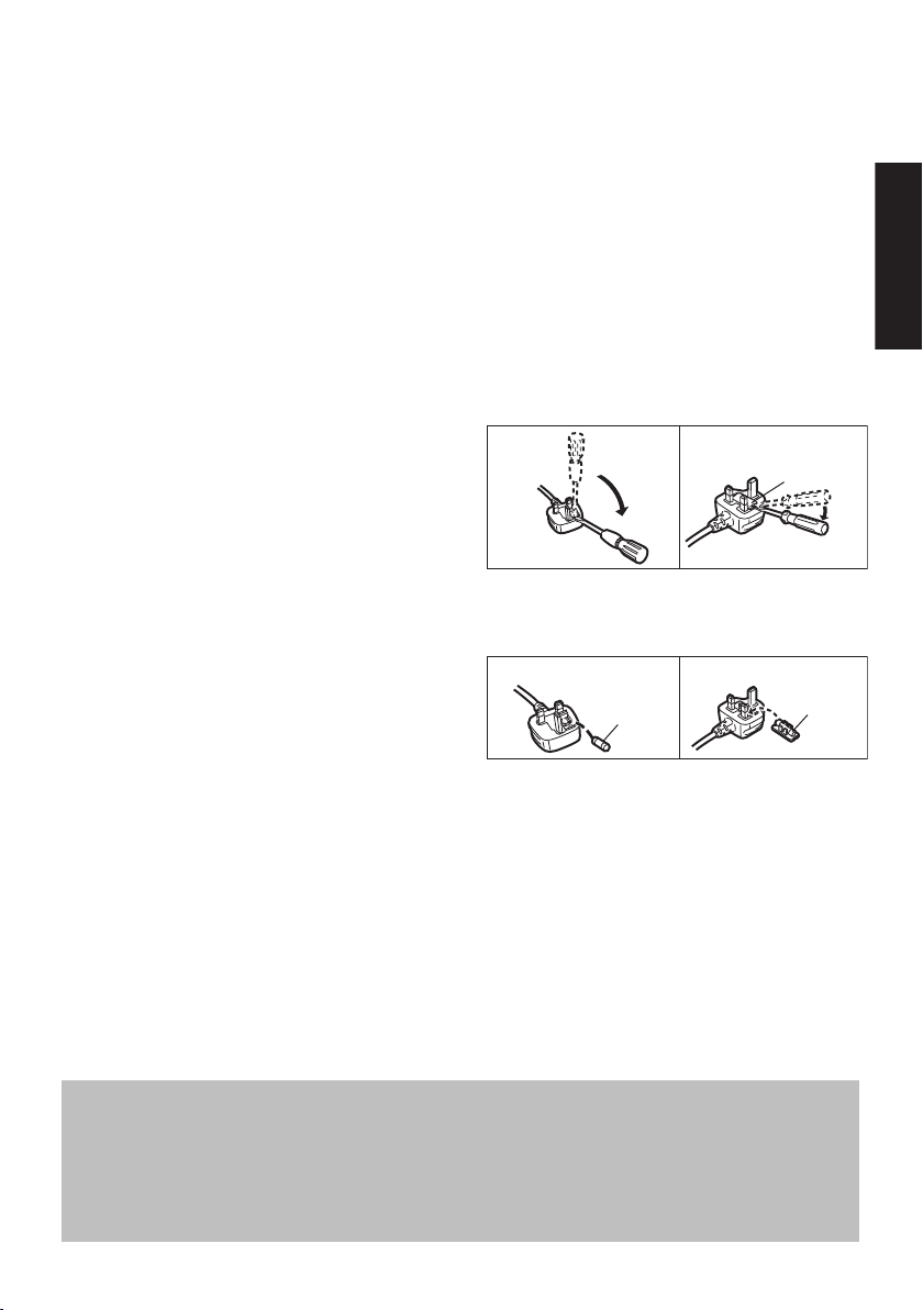
Caution for AC Mains Lead
Figure A
Figure B
Fuse cover
Figure A Figure B
Fuse
(10 ampere)
Fuse
(10 ampere)
About descriptions in these operating instructions
≥ Pages to be referred to are indicated as “> ±±”.
≥ Labels on this unit and the remote control are indicated as [±±] in these operating instructions.
≥ The illustrations shown may differ from your unit.
≥ These operating instructions are applicable to model SC-ALL70T for variety of regions. Unless otherwise indicated,
illustrations in these operating instructions are of the model for the United Kingdom and Ireland.
≥ Operations in this operating instructions are described mainly with the remote control, but you can perform the operations
on the main unit if the controls are the same.
(For the AC mains plug of three
pins)
For your safety, please read the following text
carefully.
This appliance is supplied with a moulded three
pin mains plug for your safety and convenience.
A 10-ampere fuse is fitted in this plug.
Should the fuse need to be replaced please
ensure that the replacement fuse has a rating of
10-ampere and that it is approved by ASTA or
BSI to BS1362.
Check for the ASTA mark Ï or the BSI mark Ì
on the body of the fuse.
If the plug contains a removable fuse cover you
must ensure that it is refitted when the fuse is
replaced.
If you lose the fuse cover the plug must not be
used until a replacement cover is obtained.
A replacement fuse cover can be purchased
from your local dealer.
Before use
Remove the connector cover.
How to replace the fuse
The location of the fuse differ according to the
type of AC mains plug (figures A and B).
Confirm the AC mains plug fitted and follow the
instructions below.
Illustrations may differ from actual AC mains
plug.
1. Open the fuse cover with a screwdriver.
2. Replace the fuse and close or attach the fuse
cover.
SQT0935
3

Table of contents
Safety precautions ........................................................................................... 2
Caution for AC Mains Lead ............................................................................. 3
Before use
Supplied items.................................................................................................. 5
Control reference guide................................................................................... 6
Getting started
Step 1 Connections ......................................................................................... 9
Step 2 Placement .......................................................................................... 13
Step 3 Active subwoofer wireless connection ........................................... 19
Step 4 Network settings ............................................................................... 19
Operations
Using this system .......................................................................................... 23
Streaming music over the network .............................................................. 24
Bluetooth
3D sound ......................................................................................................... 28
Sound menu ................................................................................................... 28
Setup menu ..................................................................................................... 30
Linked operations with the TV
(VIERA Link “HDAVI Control
®
operations ................................................................................... 27
TM
”) .............................................................. 33
Reference
Troubleshooting ............................................................................................. 35
About Bluetooth
Unit care .......................................................................................................... 41
Licenses .......................................................................................................... 41
Specifications ................................................................................................. 42
Limited Warranty (ONLY FOR AUSTRALIA) ................................................ 47
SQT0935
4
®
........................................................................................... 40
Getting started
Operations
Reference
Before use
Precautions
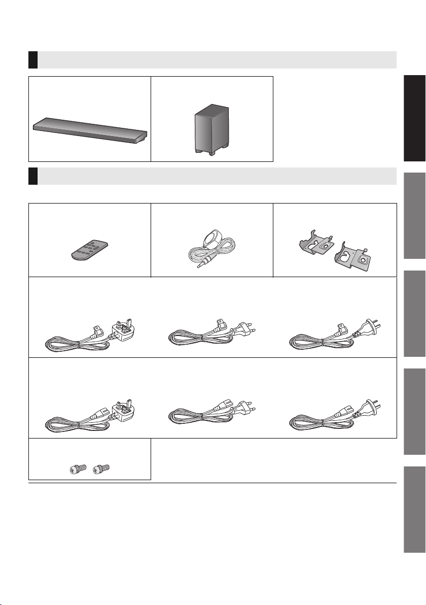
Supplied items
This system (SC-ALL70T)
Before use
∏ 1 Main unit (speaker)
(SU-ALL70T)
∏ 1 Active subwoofer
(SB-ALL70T)
Accessories
Check the supplied accessories before using this system.
∏ 1 Remote control
(with a battery)
(N2QAYC000098)
∏ 1 AC mains lead for the main unit
For the United Kingdom and Ireland
(SFQ0017)
∏ 1 AC mains lead for the active subwoofer
For the United Kingdom and Ireland
(SFQ0018)
∏ 1 IR Blaster
(SFQ0014)
For Continental Europe
(SFQ0015)
For Continental Europe
(SFQ0016)
∏ 2 Wall mount brackets
(RMQ2281A, RMQ2281B)
For Australia and New Zealand
(SFQ0021)
For Australia and New Zealand
(SFQ0022)
∏ 2 Screws
(XYN5+J14JK)
≥ Product numbers are correct as of April 2015. These may be subject to change.
≥ The supplied AC mains lead is for use with this system only.
Do not use it with other equipment. Also, do not use cords from other equipment with this system.
SQT0935
5
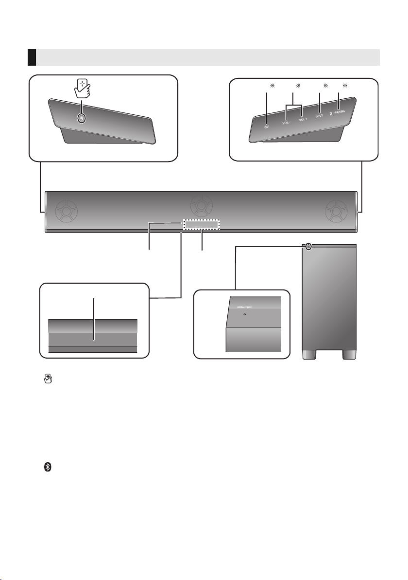
Control reference guide
8
9
7
1
6
3 42 5
Main unit
Active subwoofer
This system (Front)
1 [ ] NFC touch area (> 27)
2 [Í/I] Standby/on switch (Í/I)
Touch to switch the unit from on to standby
mode or vice versa. In standby mode, the
unit is still consuming a small amount of
power.
3[VOLj][VOLi] Adjust the volume of this
system (> 23)
4 [INPUT] Select the input source (> 23)
5 [ -PAIRING]
≥ Select the Bluetooth
source (> 23)
≥ Bluetooth
≥ Disconnecting a Bluetooth
®
pairing (> 27)
®
device as the
®
SQT0935
6
device (> 27)
6 Remote control signal sensor for table top
layout (> 8)
7 Remote control signal sensor for wall
mounting layout (> 8)
8 Display
9 WIRELESS LINK indicator (> 19)
§ These switches work just by touching the
marks. Each time you touch the switch,
there will be a beep sound.
The beep sound setting can be changed.
(> 30)
Before use
3
4
5
1
2
6
6
7
1
2
Main unit
Active subwoofer
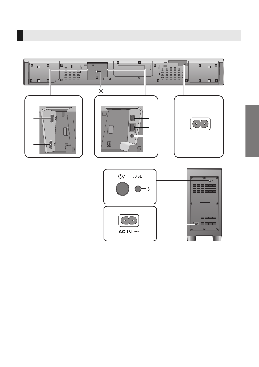
This system (Rear)
1 HDMI AV OUT (TV (ARC)) terminal (ARC
compatible) (> 9, 10)
2 HDMI AV IN (BD/DVD) terminal (> 11)
3 OPTICAL DIGITAL AUDIO IN (TV) terminal
(> 10)
4 LAN terminal (> 22)
5 Ir SYSTEM terminal (> 11)
6 AC IN terminal (> 12)
7[Í/I] Active subwoofer on/off button (> 19)
§1 USB port (for service use only)
§2 The I/D SET button is only used when the
main unit is not paired with the active
subwoofer. (> 39)
SQT0935
7
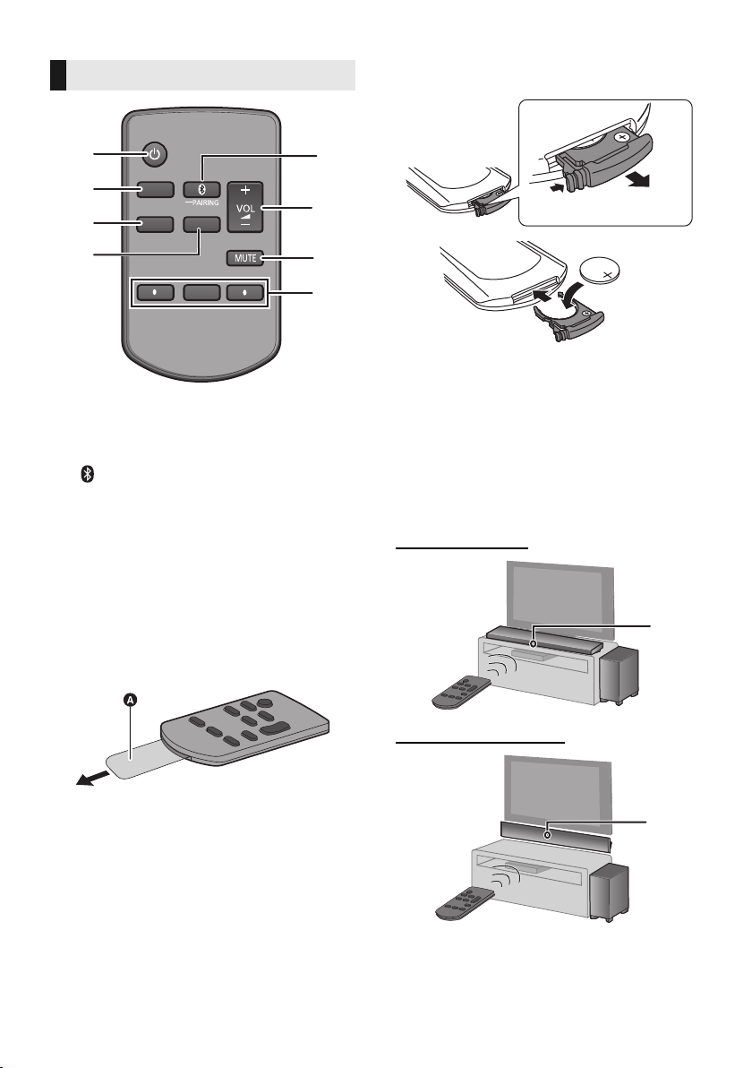
Remote control
SOUND
INPUT
SETUP
OK
1
5
6
7
8
2
3
4
∫ To replace a button-type battery
Battery type: CR2025 (Lithium battery)
≥ Set the button-type battery with its (i) mark
facing upward.
1[Í] Turn the main unit on or off (> 23)
2 [INPUT] Select the input source (> 23)
3 [SETUP] Select the setup menu (> 30)
4 [SOUND] Select the sound menu (> 28)
5 [ -PAIRING]
≥ Select the Bluetooth
source (> 23)
≥ Bluetooth
®
pairing (> 27)
®
device as the
≥ Disconnecting a Bluetooth
6[j VOL i] Adjust the volume of this system
(> 23)
7 [MUTE] Mute the sound (> 23)
8[4][OK][3] Select and confirm the option
∫ Before using for the first time
Remove the insulation sheet A.
≥ Dispose of the insulation sheet responsibly
after removing it.
®
device (> 27)
∫ About remote control signal sensor
The remote control signal sensor is located
on the main unit.
≥ Use the remote control within the correct
operation range.
Distance: Within approx. 7 m directly in front
Angle: Approx. 30
o
left and right
For table top layout
For wall mounting layout
B Remote control signal sensor for table top
layout
C Remote control signal sensor for wall
mounting layout
SQT0935
8

Getting started
Before use
Getting started
Step 1 Connections
≥ Turn off all equipment before connection and
read the appropriate operating instructions.
Do not connect the AC mains lead until all
other connections are completed.
∫ HDMI (High-Definition Multimedia
Interface)
≥ The HDMI connection supports VIERA Link “HDAVI
Control” (> 33) when used with a compatible
Panasonic TV.
≥ Use the ARC compatible High Speed HDMI Cables.
Non-HDMI-compliant cables cannot be utilised.
≥ It is recommended that you use Panasonic’s HDMI
cable.
∫ HDMI standby pass-through
Even if the main unit is in standby mode, the audio and/
or video signal from the device connected to the HDMI
AV IN terminal will be sent to the TV connected to the
HDMI AV OUT terminal (the sound will not be output
from this system).
∫ 3D compatibility
Compatible with FULL HD 3D TV and Blu-ray Disc
player.
≥ The main unit can pass-through the 3D video signal
from a 3D compatible Blu-ray Disc player to a FULL
HD 3D TV.
Connection with the TV
1 Verify if the TV’s HDMI terminal is
labelled “HDMI (ARC)”.
Connection differs depending on the label
printed next to the HDMI terminal.
Labelled “HDMI (ARC)”:
Connection [A]
Not Labelled “HDMI (ARC)”:
Connection [B]
∫ What is ARC?
ARC is an abbreviation of Audio Return Channel, also
known as HDMI ARC. It refers to one of the HDMI
functions. When you connect the main unit to the
terminal labelled “HDMI (ARC)” on the TV, the optical
digital audio cable that is usually required in order to
listen to sound from a TV is no longer required, and TV
pictures and sound can be enjoyed with a single HDMI
cable.
2 Make the connection.
∫ 4K/60p compatibility
Compatible with 4K Ultra HD TV and Blu-ray Disc
player.
≥ This system can pass-through the 4K content of a 4K
compatible equipment to a 4K Ultra HD TV.
≥ When connecting to 4K compatible equipment and
4K Ultra HD TV, use High Speed HDMI cables which
support 18 Gbps bandwidth.
SQT0935
9
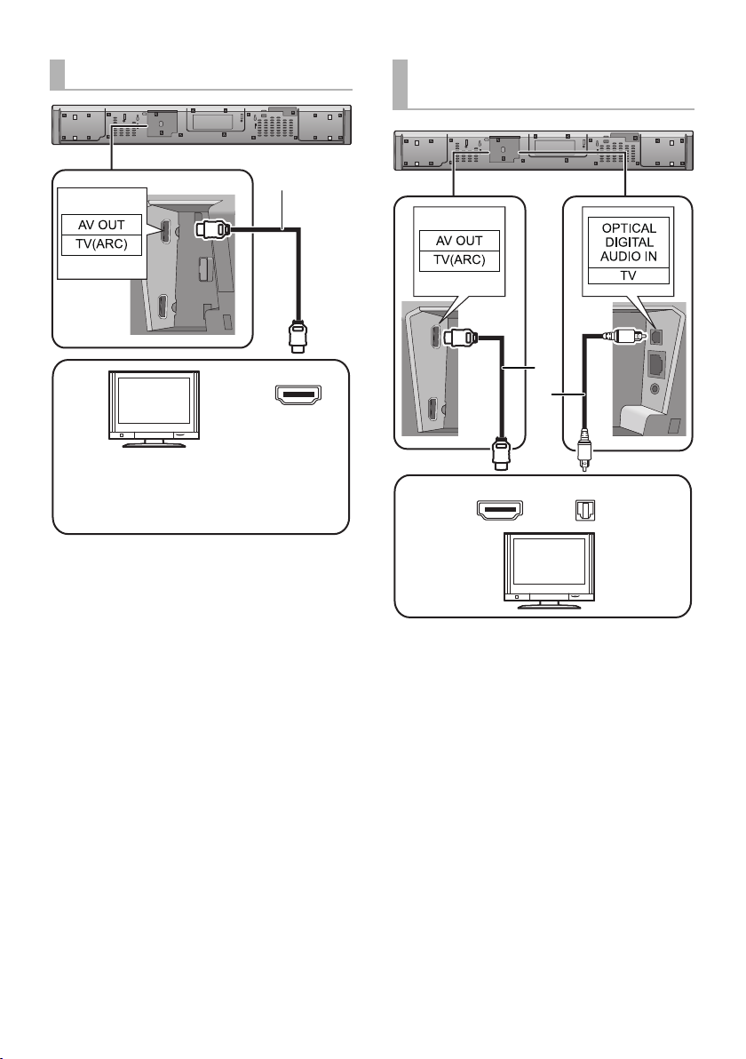
[A] Labelled “HDMI (ARC)”
HDMI IN (ARC)
TV
Be sure to connect to the TV’s ARC
compatible terminal. (Refer to the operating
instructions for the TV.)
TV
[B] Not Labelled “HDMI
(ARC)”
A HDMI cable
10
SQT0935
HDMI IN
A HDMI cable
B Optical digital audio cable
≥ When you use the optical digital audio cable, insert
the tip correctly into the terminal.
OPTICAL
OUT
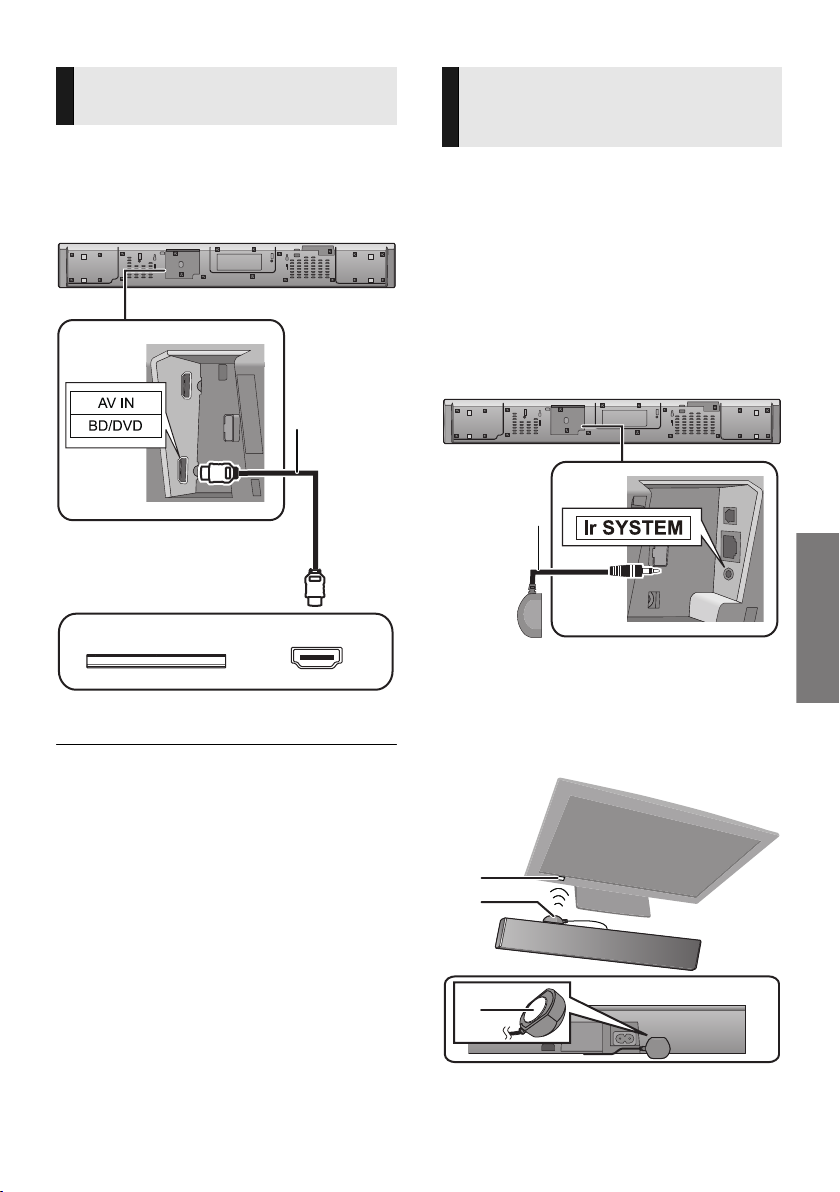
Getting started
Connection from an HDMI
e.g., Blu-ray Disc player
compatible device
You can direct the audio signal from the
connected Blu-ray Disc player, DVD player, Set
Top Box, etc. to this system.
Preparation
≥ Connect the main unit to the TV. (> 9)
HDMI OUT
A HDMI cable
≥ Refer to the operating instructions of the connected
HDMI compatible device for the necessary setting, to
output the video and audio signals.
≥ When connecting to 4K compatible equipment and 4K
Ultra HD TV, use High Speed HDMI cables which support
18 Gbps bandwidth.
Using the IR Blaster
(When the remote control does not
work properly)
Depending on how the main unit is setup, it may
block the TV’s remote control signal sensor,
stopping the TV’s remote control from working.
Use the supplied Ir system cable if this occurs.
The TV remote control signals received by the
main unit are sent to the TV to operate it.
≥ For the operation range, refer to page 8.
≥ Do not use any other IR Blaster except the
supplied one.
1 Connect the jack plug to the main
unit’s Ir SYSTEM terminal.
A IR Blaster (supplied)
2 Place the infrared emitter in sight of
the TV’s remote control signal sensor.
Placement example
On the rear of the main unit:
B TV remote control signal sensor
C Infrared emitter
D Adhesive tape
SQT0935
11
3 Aim the TV’s remote control at this
※
system’s remote control sensor and
operate the TV.
≥ For the location of the TV’s remote control signal sensor,
refer to the operating instructions for the TV.
≥ Select a location that suits the environment.
≥ Make sure to clean the surface, where the adhesive tape
is to be attached.
≥ If you peel off the adhesive tape, the surface may
become damaged and exposed adhesive may remain.
Once you have confirmed the TV is operating correctly,
secure it by attaching the adhesive tape.
≥ When the TV receives signals from both its remote
control and the IR Blaster, their signals may interfere with
each other, making it impossible for you to operate the
TV.
Try using the TV’s remote control from a different angle.
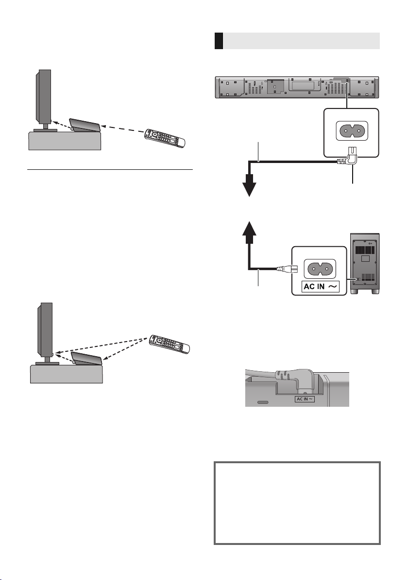
AC mains lead connection
≥ Connect only after all other connections
are completed.
A To a household mains socket
B AC mains lead for the main unit (supplied)
C AC mains lead for the active subwoofer
(supplied)
§ Insert the AC mains lead fully into the main
unit.
12
SQT0935
≥ This system consumes a small amount of AC
power (> 42) even when it is turned off. In the
interest of power conservation, if you will not
be using this system for a long time, unplug it
from the household mains socket.
Saving energy
The main unit is designed to conserve its
power consumption and save energy.
≥ The main unit will automatically switch to
standby mode when no signal is input and
no operation is performed for approx. 20
minutes. Refer to page 30, “AUTO
POWER DOWN” to turn this function off.
Getting started
Precautions
Step 2 Placement
Safety Precautions
Professional installation is required.
The installation should never be done by
any other than a qualified installation
specialist.
PANASONIC DISCLAIMS ANY PROPERTY
DAMAGE AND/OR SERIOUS INJURY,
INCLUDING DEATH RESULTING FROM
IMPROPER INSTALLATION OR
INCORRECT HANDLING.
≥ Be sure to install the main unit as indicated within this
operating Instructions.
≥ Attach using techniques suited to the structure and
materials of the installation location.
Caution
≥ This system is to be used only as indicated
in these instructions. Failure to do so may
lead to damage to the amplifier and/or the
speaker, and may result in the risk of fire.
Consult a qualified service person if
damage has occurred or if you experience
a sudden change in performance.
≥ Do not attempt to attach the main unit to a
wall using methods other than those
described in this manual.
≥ Do not hold the main unit in one hand to avoid injury,
you may drop the main unit when carrying it.
≥ To prevent damage or scratches, lay down a soft
cloth and perform the assembly on it.
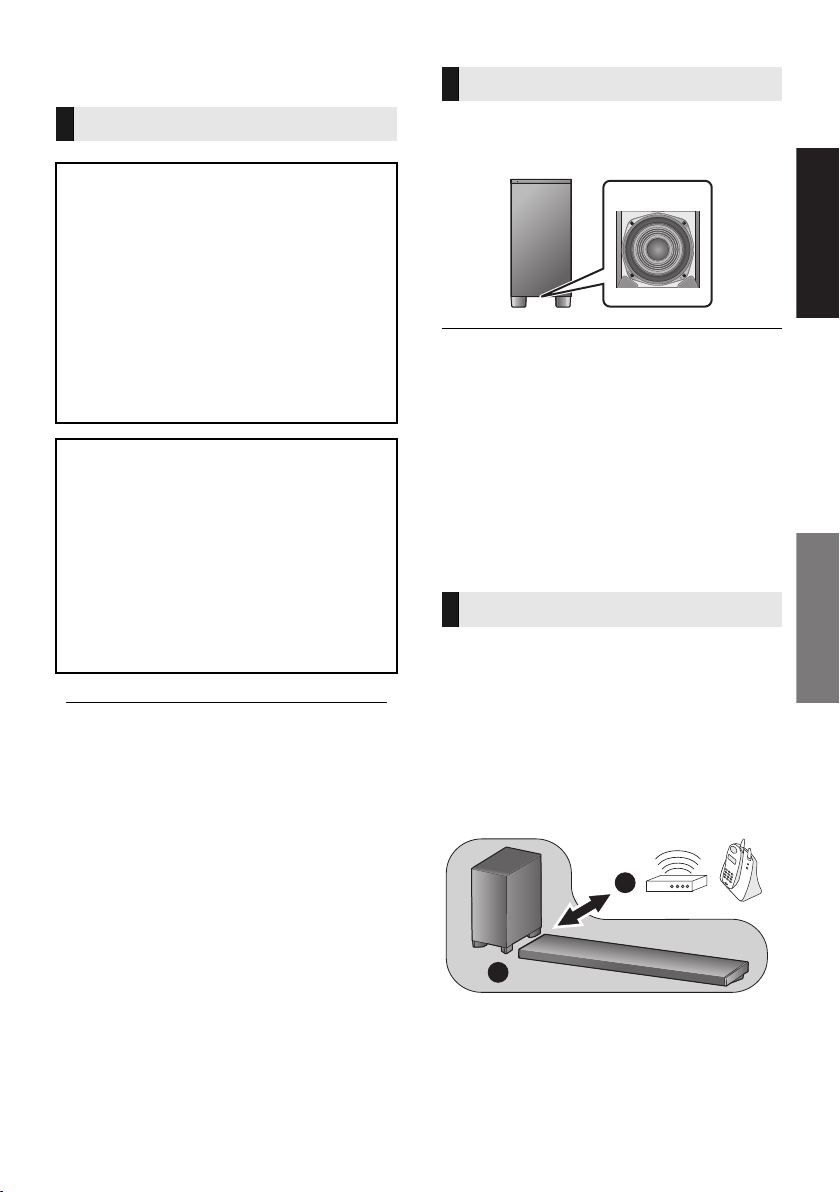
The active subwoofer
When carrying the active subwoofer
Take care not to damage the inside speaker
unit.
≥ The speaker protection cover is attached to the speaker
unit inside the subwoofer. Remove it before use.
≥ When the subwoofer is brought close to CRT TVs and
other display devices, the magnets in the speaker may
cause some colour irregularities or image distortion. If
this happens, move the active subwoofer to a place
where these symptoms do not occur.
≥ Interference may occur if the TV has wireless LAN
functionality, causing some communication problems
(sound is interrupted, sound skips, there is a lot of noise,
etc.). If this happens, move the active subwoofer to a
place where interference does not occur.
Wireless interference
Interference may occur if you are using other
devices (wireless LAN/microwave ovens/
cordless phones, etc.) that use the 2.4 GHz
frequency band, causing some communication
problems (sound is interrupted, sound skips,
there is a lot of noise, etc.).
If this happens, separate the other electronic
equipment from the main unit and active
subwoofer so that interference does not occur.
B
A
A Main unit/active subwoofer
B Wireless router, cordless phone and other
electronic devices
SQT0935
13
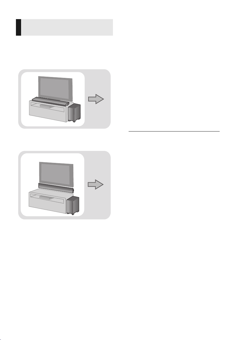
Selecting the placement
Page 15
Page 16
method
Choose a placement method that suits you best.
When placing the main unit in a rack or
on a table
≥ Place the main unit on a flat and horizontal
surface.
∫ When placing the main unit in front
of the TV
The main unit may block or interfere with the
TV’s various sensors (C.A.T.S. (Contrast
Automatic Tracking System) sensor, remote
control sensor, etc.) and the 3D Eyewear
transmitters on a 3D compatible TV.
≥ If interference occurs, move the main unit
further away from the TV. If the TV still does
not function correctly, try using it in a rack or in
the wall mount position.
∫ If the TV’s remote control sensor is
blocked by the main unit
Try using the TV’s remote control from a
different angle. If the problem persists, you can
use the supplied IR Blaster to relay the signal to
the TV. (> 11 )
When attaching the main unit to a wall
≥ Place the main unit on a flat and vertical
surface.
≥ Place the active subwoofer within a few meters of the
main unit and in a horizontal position with the top
panel facing upward.
≥ Do not use the main unit or the active subwoofer in a
metal cabinet.
≥ Placing the active subwoofer too close to the walls
and corners can result in excessive bass. Cover walls
and windows with thick curtains.
≥ Keep magnetised items away. Magnetised cards,
watches, etc., can be damaged if placed too close to
the main unit and active subwoofer.
14
SQT0935
Getting started
Precautions
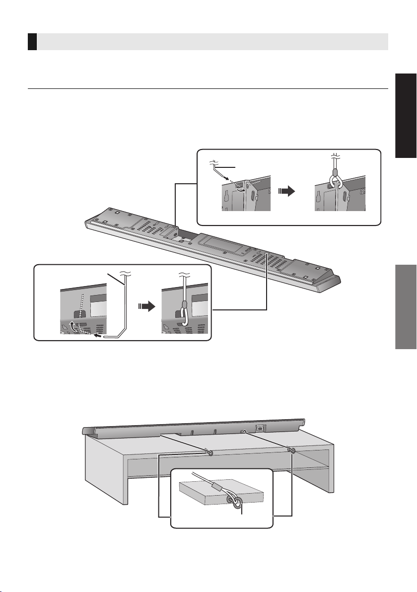
When placing the main unit in a rack or on a table
Additionally required accessories (commercially available)
≥ Fall prevention cord ..................................................................................................................... k 2
≥ Screw eyes (to attach the fall prevention cord) ............................................................................ k 2
≥ Use commercially available screws that are capable of supporting over 26 kg.
≥ Use a cord that is capable of supporting over 26 kg (with a diameter of about 1.5 mm).
≥ Lay the unit on a blanket or soft cloth for assembly.
1 Attach the cord to the main unit.
A Cord
§ If the cord cannot be threaded through the holes, try bending the cord in 2 locations,
§
about 5 mm apart from the tip, at an angle of 45
o
(as illustrated above).
2 Place the main unit in the desired position and attach each cord onto the rack or table.
≥ Make sure that the slack of the cord is minimal.
≥ Do not lean the main unit against the TV or wall.
B Screw eye
≥Attach at a position capable of supporting over 26 kg.
≥Depending on the placement of the main unit, the screwing position of the screw eye may differ.
SQT0935
15
 Loading...