

Panasonic SBZT-1-PP, SBZT-2-PP, SCZT-2-PP, SUZT-2-PP Service manual
PSG1003022CE
Home Theater Audio System
Model No. SC-ZT2PP
SU-ZT2PP
SB-ZT1PP
SB-ZT2PP
Product Color: (K)...Black Type (SC-ZT2/SU-ZT2)
(KA)...Black Type (SU-ZT2)
(K1)...Black Type (SB-ZT2)
(S)...Silver Type (SC-ZT2)
(S1)...Silver Type (SB-ZT1)
A6
© Panasonic Corporation 2010. All rights reserved.
Unauthorized copying and distribution is a violation of
law.

TABLE OF CONTENTS
PAG E PAG E
1 Safety Precautions -----------------------------------------------3
1.1. General Guidelines ----------------------------------------3
1.2. Before Repair and Adjustment--------------------------4
1.3. Caution for Fuse Replacement -------------------------4
1.4. Protection Circuitry-----------------------------------------4
1.5. Safety Part Information -----------------------------------4
2Warning--------------------------------------------------------------6
2.1. Prevention of Electro Static Discharge (ESD)
to Electrostatically Sensitive (ES) Devices ----------6
2.2. Service caution based on Legal restrictions---------7
3 Service Navigation------------------------------------------------8
3.1. Service Information ----------------------------------------8
4 Specifications ------------------------------------------------------9
4.1. Main Unit (SU-ZT2) ----------------------------------------9
4.2. Speaker Unit (SB-ZT1/2) ---------------------------------9
5 Location of Controls and Components------------------ 10
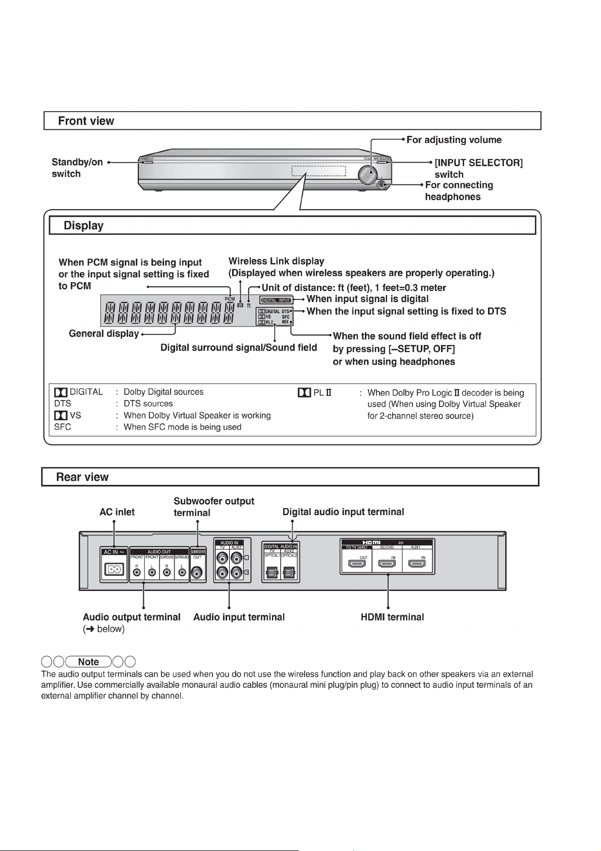
5.1. Main Unit (SU-ZT2) -------------------------------------- 10
5.2. Speaker Unit (SB-ZT1/2) ------------------------------- 11
5.3. Remote Control ------------------------------------------- 11
6 Installation--------------------------------------------------------- 12
6.1. Basic Connections --------------------------------------- 13
6.2. AC power supply connection ------------------------- 17
7 Speaker setting (SB-ZT1/2) ---------------------------------- 18
7.1. Setting the speakers (Front and Surround
speakers)--------------------------------------------------- 18
7.2. Setting surround speakers ----------------------------- 20
7.3. Initialize the Speaker Setting -------------------------- 21
8 Self-diagnostic and special mode setting --------------22
8.1. Activating Service Mode-------------------------------- 22
8.2. Activating Doctor Mode --------------------------------- 22
8.3. Error Codes Display List-------------------------------- 22
8.4. Inspection Mode ------------------------------------------ 23
8.5. Returning to Normal Display -------------------------- 24
9 Troubleshooting------------------------------------------------- 25
9.1. HDMI Checking Method -------------------------------- 25
9.2. Troubleshooting Flow Chart --------------------------- 27
10 Disassembly and Assembly Instructions --------------- 31
10.1. Caution------------------------------------------------------ 31
10.2. Main Parts Location Diagram ------------------------- 33
10.3. Disassembly flow chart ---------------------------------35
10.4. Main Unit (SU-ZT2) -------------------------------------- 37
10.5. Speaker Unit (SB-ZT1/2) ------------------------------- 48
11 Service Position ----------------------------------------------- 106
11.1. Main Unit (SU-ZT2) ------------------------------------ 106
11.2. Speaker Unit (SB-ZT1/2) ----------------------------- 108
12 Voltage Measurement & Waveform Chart------------- 11 6
12.1. Main Unit (SU-ZT2) -------------------------------------116
12.2. Speaker Unit (SB-ZT2) ------------------------------- 126
12.3. Waveform Chart ---------------------------------------- 128
13 Illustration of IC’s, Transistors and Diodes ---------- 131
14 Overall Simplified Block ------------------------------------ 133
14.1. Signal Flow (SU-ZT2) --------------------------------- 133
15 Block Diagram ------------------------------------------------- 134
15.1. Main Unit (SU-ZT2) ------------------------------------ 134
15.2. Speaker Unit (SB-ZT1/2) ----------------------------- 141
16 Wiring Connection Diagram ------------------------------- 145
16.1. MAIN UNIT (SU-ZT2) --------------------------------- 145
16.2. Speaker Unit (SB-ZT1/2) ----------------------------- 146
17 Schematic Diagram Notes ----------------------------------147
18 Schematic Diagram -------------------------------------------149
18.1. Main Unit (SU-ZT2) ------------------------------------ 149
18.2. Speaker Unit (SB-ZT1/2) ----------------------------- 163
19 Printed Circuit Board-----------------------------------------169
19.1. Main Unit (SU-ZT2) ------------------------------------ 169
19.2. Speaker Unit (SB-ZT1/2) ----------------------------- 173
20 Terminal Function of IC’s ----------------------------------- 177
20.1. IC8001 (RFKWMZT2PPK2) MICRO
PROCESSOR -------------------------------------------177
21 Exploded View and Replacement Parts List---------- 179
21.1. Exploded View and Mechanical Replacement
Parts List--------------------------------------------------179
21.2. Electrical Replacement Parts List ------------------185
2
1 Safety Precautions
1.1. General Guidelines
1. When servicing, observe the original lead dress. If a short circuit is found, replace all parts which have been overheated or
damaged by the short circuit.
2. After servicing, see to it that all the protective devices such as insulation barriers, insulation papers shields are properly
installed.
3. After servicing, carry out the following for leakage current checks to prevent the customer from being exposed to shock hazards.
1.1.1. Leakage Current Cold Check
1. Unplug the AC cord and connect a jumper between the two prongs on the plug.
2. Using an ohmmeter measure the resistance value, between the jumpered AC plug and each exposed metallic cabinet part on
the equipment such as screwheads, connectors, control shafts, etc. When the exposed metallic part has a return path to the
chassis, the reading should be between 1mW and 5.2mW. When the exposed metal does not have a return path to the chassis, the reading must be .
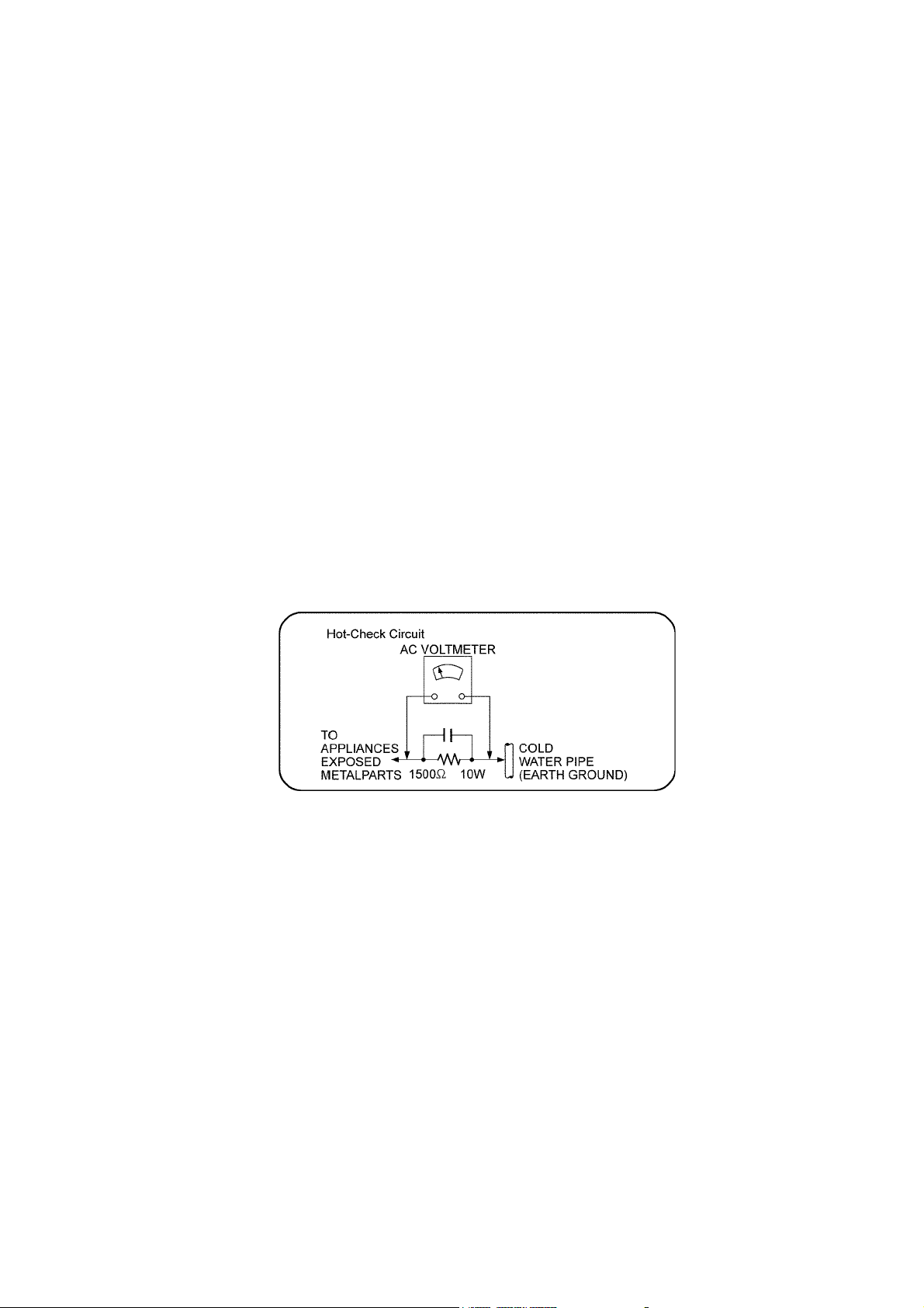
1.1.2. Leakage Current Hot Check
1. Plug the AC cord directly into the AC outlet. Do not use an isolation transformer for this check.
2. Connect a 1.5kW, 10 watts resistor, in parallel with a 0.15mF capacitors, between each exposed metallic part on the set and a
good earth ground such as a water pipe, as shown in Figure 1.
3. Use an AC voltmeter, with 1000 ohms/volt or more sensitivity, to measure the potential across the resistor.
4. Check each exposed metallic part, and measure the voltage at each point.
5. Reverse the AC plug in the AC outlet and repeat each of the above measurements.
6. The potential at any point should not exceed 0.75 volts RMS. A leakage current tester (Simpson Model 229 or equivalent)
may be used to make the hot checks, leakage current must not exceed 1/2 milliamp. should the measurement is outside of
the limits specified, there is a possibility of a shock hazard, and the equipment should be repaired and re-checked before it is
returned to the customer.
Fig. 1
3
1.2. Before Repair and Adjustment
Disconnect AC power, discharge Power Supply Capacitors for :
Main Unit (SU-ZT2)
(C5501, C5502, C5503, C5509) through a 10Ω, 1W resistor to ground.
Speaker Unit (SB-ZT1/2)
(C5701, C5703, C5704) through a 10Ω, 1W resistor to ground.
DO NOT SHORT-CIRCUIT DIRECTLY (with a screwdriver blade, for instance), as this may destroy solid state devices.
After repairs are completed, restore power gradually using a variac, to avoid overcurrent.
• Current consumption at AC 120 V, 60 Hz in NO SIGNAL mode should be 100~800 mA.
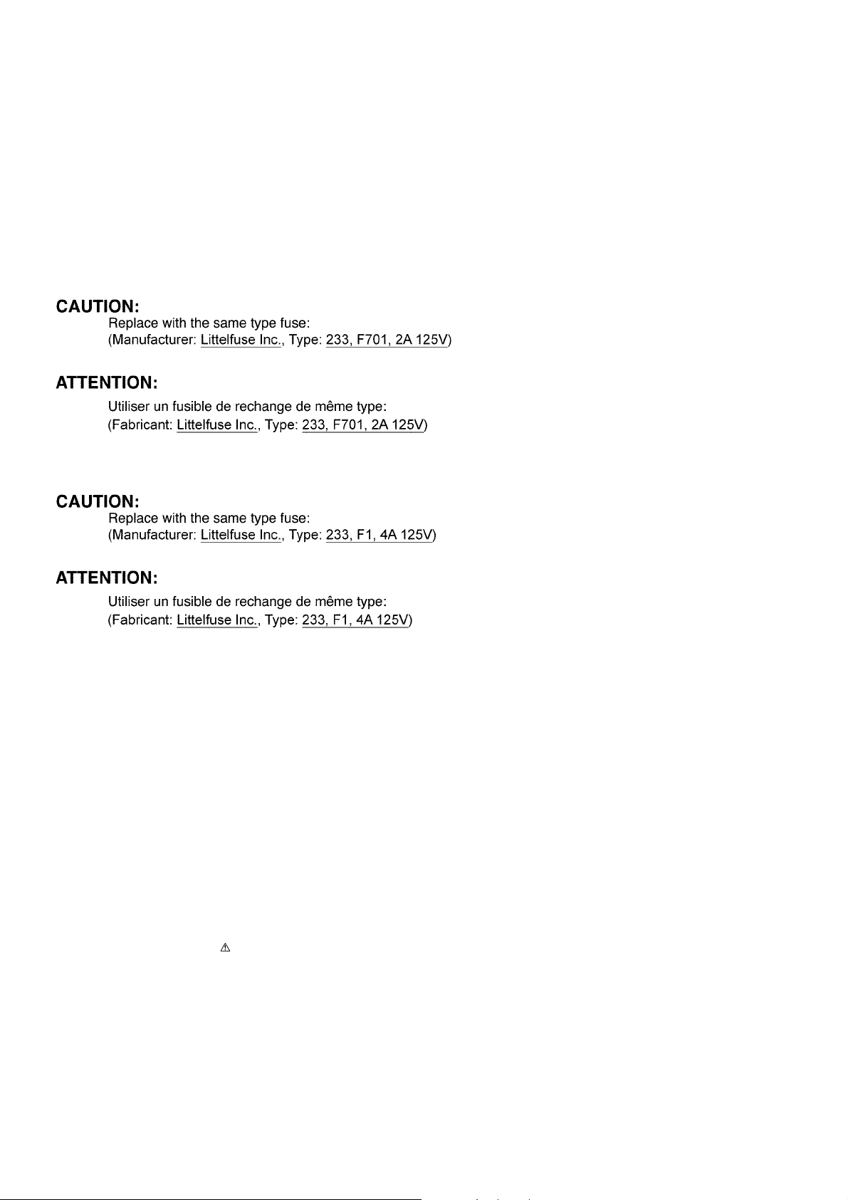
1.3. Caution for Fuse Replacement
Main Unit (SU-ZT2)
Speaker Unit (SB-ZT1/2)
1.4. Protection Circuitry
The protection circuitry may have operated if either of the following conditions are noticed:
• No sound is heard when the power is turned on.
• Sound stops during a performance.
The function of this circuitry is to prevent circuitry damage if, for example, the positive and negative speaker connection wires are
"shorted", or if speaker systems with an impedance less than the indicated rated impedance of the amplifier are used.
If this occurs, follow the procedure outlines below:
1. Turn off the power.
2. Determine the cause of the problem and correct it.
3. Turn on the power once again after one minute.
Note:
When the protection circuitry functions, the unit will not operate unless the power is first turned off and then on again.
1.5. Safety Part Information
Safety Parts List:
There are special components used in this equipment which are important for safety.
These parts are marked by in the Schematic Diagrams, Exploded View & Replacement Parts List. It is essential that these
critical parts should be replaced with manufacturer’s specified parts to prevent shock, fire or other hazards. Do not modify the
original design without permission of manufacturer.
4
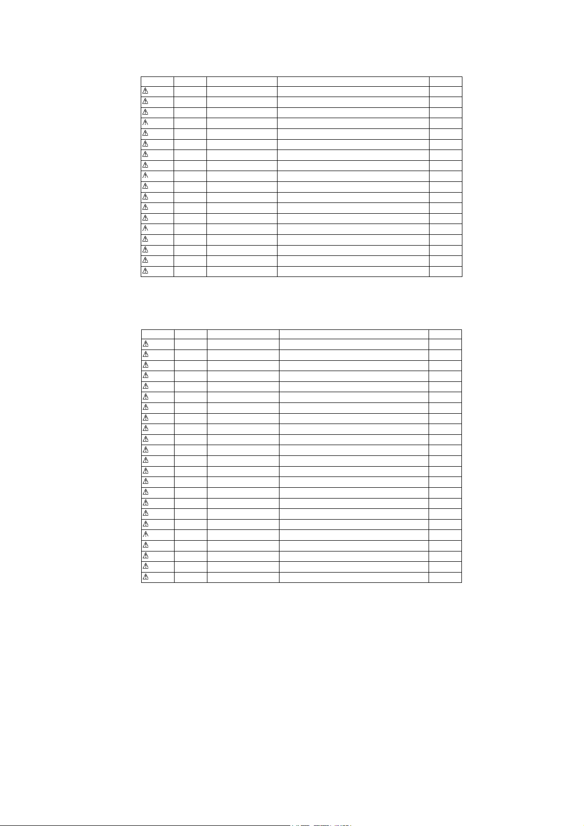
1.5.1. Main Unit (SU-ZT2)
Safety Ref. No. Part No. Part Name & Description Remarks
11 RGR0393A-H1 REAR PANEL
30 RKM0613-K TOP CABINET
A2 K2CB2CB00021 AC CORD
A3 VQT2T88 O/I (En/Cf)
A3 VQT2R70 O/I (En/Cf)
DZ5501 ERZV10V511CS ZNR
L5500 ELF18N005A LINE FILTER
L5501 ELF15N035AN LINE FILTER
T5501 ETS25AD1V6AG MAIN TRANSFORMER
T5551 G4D1A0000117 SWITCHING TRANSFORMER
PC5501 B3PBA0000402 PHOTO COUPLER
F701 K5D202APA008 FUSE
IP5501 K5H7512A0010 PROTECTOR
P5501 K2AB2B000007 AC INLET
C5501 ECQU2A104MLC 0.1uF
C5502 ECQU2A104MLC 0.1uF
C5503 F1BAF1020020 1000pF
C5509 F1BAF1020020 1000pF
1.5.2. Speaker Unit (SB-ZT1/2)
Safety Ref. No. Part No. Part Name & Description Remarks
100 REX1346-1 BLACK WIRE (SMPS-AC)
101 REX1356-1 RED WIRE (SMPS-AC)
113 RGN2979B-K1 SPEC LABEL S1
113 RGN2979H-K SPEC LABEL K1
114 RGN2980B-K1 WIRELESS LABEL S1
114 RGN2980H-K WIRELESS LABEL K1
PCB1 REP4527B-P SMPS P.C.B. (RTL)
PCB2 REP4527B-P AC INLET P.C.B. (RTL)
PCB6 REPX0679D RX P.C.B.
DZ5701 ERZV10V511CS ZNR
L5702 ELF19H010A LINE FILTER
T5701 ETS28BH145AC MAIN TRANSFORMER
T5751 ETS19AB2C6AG SUB TRANSFORMER
PC5701 B3PBA0000402 PHOTO COUPLER
PC5720 B3PBA0000402 PHOTO COUPLER
PC5799 B3QAZ0000062 PHOTO COUPLER
F1 K5D402APA008 FUSE
TH5702 D4CAA5R10001 THERMISTOR
P5701 K2AB2B000007 AC INLET
C5700 F1BAF2220023 2200pF
C5701 ECQU2A104MLC 0.1uF
C5703 ECQU2A224MLC 0.22uF
C5704 F1BAF1020020 1000pF
5

2Warning
2.1. Prevention of Electro Static Discharge (ESD) to Electrostatically Sensi-
tive (ES) Devices
Some semiconductor (solid state) devices can be damaged easily by static electricity. Such components commonly are called Electrostatically Sensitive (ES) Devices. Examples of typical ES devices are integrated circuits and some field-effect transistors and
semiconductor “chip” components. The following techniques should be used to help reduce the incidence of component damage
caused by electrostatic discharge (ESD).
1. Immediately before handling any semiconductor component or semiconductor-equiped assembly, drain off any ESD on your
body by touching a known earth ground. Alternatively, obtain and wear a commercially available discharging ESD wrist strap,
which should be removed for potential shock reasons prior to applying power to the unit under test.
2. After removing an electrical assembly equiped with ES devices, place the assembly on a conductive surface such as alumin-
ium foil, to prevent electrostatic charge build up or exposure of the assembly.
3. Use only a grounded-tip soldering iron to solder or unsolder ES devices.
4. Use only an anti-static solder remover device. Some solder removal devices not classified as “anti-static (ESD protected)” can
generate electrical charge sufficient to damage ES devices.
5. Do not use freon-propelled chemicals. These can generate electrical charges sufficient to damage ES devices.
6. Do not remove a replacement ES device from its protective package until immediately before you are ready to install it. (Most
replacement ES devices are packaged with leads electrically shorted together by conductive foam, aluminium foil or comparable conductive material).
7. Immediately before removing the protective material from the leads of a replacement ES device, touch the protective material
to the chassis or circuit assembly into which the device will be installed.
Caution:
Be sure no power is applied to the chassis or circuit, and observe all other safety precautions.
8. Minimize bodily motions when handling unpackaged replacement ES devices. (Otherwise harmless motion such as the
brushing together of your clothes fabric or the lifting of your foot from a carpeted floor can generate static electricity (ESD) suf-
ficient to damage an ES device).
6

2.2. Service caution based on Legal restrictions
2.2.1. General description about Lead Free Solder (PbF)
The lead free solder has been used in the mounting process of all electrical components on the printed circuit boards used for this
equipment in considering the globally environmental conservation.
The normal solder is the alloy of tin (Sn) and lead (Pb). On the other hand, the lead free solder is the alloy mainly consists of tin
(Sn), silver (Ag) and Copper (Cu), and the melting point of the lead free solder is higher approx.30 degrees C (86°F) more than that
of the normal solder.
Definition of PCB Lead Free Solder being used
The letter of “PbF” is printed either foil side or components side on the PCB using the lead free solder.
(See right figure)
Service caution for repair work using Lead Free Solder (PbF)
• The lead free solder has to be used when repairing the equipment for which the lead free solder is used.
(Definition: The letter of “PbF” is printed on the PCB using the lead free solder.)
• To put lead free solder, it should be well molten and mixed with the original lead free solder.
• Remove the remaining lead free solder on the PCB cleanly for soldering of the new IC.
• Since the melting point of the lead free solder is higher than that of the normal lead solder, it takes the longer time to melt the
lead free solder.
• Use the soldering iron (more than 70W) equipped with the temperature control after setting the temperature at 350±30 degrees
C (662±86°F).
Recommended Lead Free Solder (Service Parts Route.)
• The following 3 types of lead free solder are available through the service parts route.
RFKZ03D01K-----------(0.3mm 100g Reel)
RFKZ06D01K-----------(0.6mm 100g Reel)
RFKZ10D01K-----------(1.0mm 100g Reel)
Note
* Ingredient: Tin (Sn), 96.5%, Silver (Ag) 3.0%, Copper (Cu) 0.5%, Cobalt (Co) / Germanium (Ge) 0.1 to 0.3%
7

3 Service Navigation
3.1. Service Information
This service manual contains technical information which will allow service personnel’s to understand and service this model.
Please place orders using the parts list and not the drawing reference numbers.
If the circuit is changed or modified, this information will be followed by supplement service manual to be filled with original service
manual.
• Printed Circuit Boards:
This model supports to wireless speakers (SB-ZT1/2)
The TX Module P.C.B. and RX Module P.C.B. used for wireless signal transmission are supplied as an assembled module.
- TX Module P.C.B. (Part No.: REPX0678D)
- RX Module P.C.B. (Part No.: REPX0679D)
Note: Retention time limit applies.
• Micro-processor IC
This model uses BGA IC (IC6001). Please confirm function and operation before replacement to new part.
Part No. for IC6001 (RFKB4528AA-M)
8

4 Specifications
4.1. Main Unit (SU-ZT2)
Q PRE AMPLIFIER SECTION
Input sensitivity / Input Impedance
TV, AUX3 600 mV / 47 kΩ
S/N ratio (IHF A)
BD/DVD, TV, AUX1, AUX2 (Digital
Input)
Tone controls
BASS 50 Hz, +6 to -6 dB
TREBLE 20 kHz, +6 to -6 dB
Input / Output terminal
Audio Input
Analogue Input (TV, AUX3) 2
Optical Digital Input (TV, AUX2) 2
Audio Output
Audio Output (Front L/R, Surround
L/R)
Subwoofer Output 1
Headphone Output (16 to 64 Ω)1
Video/Audio
HDMI Input (BD/DVD, AUX1) 2
HDMI Output (TV) 1
This system supports “HDAVI Control 4” function.
Q MAIN UNIT GENERAL
Power supply AC 120 V, 60 Hz
Power consumption 16 W
In standby condition 0.5 W
In standby condition (HDMI off
mode)
Dimensions (WxHxD) 430mm x 59mm x 262mm
(16-15/16”x2-5/16”x10-5/16”)
Mass [Weight] Approx. 2 kg (4.4 lb.)
Operating temperature range 0°C to 40°C (32°F to 104°F)
Operating humidity range 20% to 80% RH (no condensa-
Q WIRELESS SECTION
Frequency of the using band 2.4000 GHz to 2.4835 GHz
Number of using channels 3
The reaching distance 15m (49ft)*1
*1 It is under the condition as follows.
At same room indoor, there is not an obstacle between the main unit
and the speaker.
And installing a main unit in the position with equal to or more than 50
cm height.
80 dB (IHF ‘66)
0.2 W
tion)
Mid High part 2.4 x 10 cm flat type x 4
Q SPEAKER GENERAL*2
Power supply AC 120 V, 60 Hz
Power consumption 20 W
Wireless link standby 0.8 W
In standby condition 0.1 W
Dimensions (WxHxD) 290mm x 1231mm x 290mm
Mass [Weight] Approx. 3.9 kg (8.6 lb.)
Operating temperature range 0°C to 40°C (32°f to 104°F)
Operating humidity range 20% to 80% RH (no condensa-
*2 : per 1 speaker
*3 : use 2 speakers
Note:
1. Specifications are subject to change without notice.
2. Total harmonic distortion is measured by the digital spectrum analyzer.
2. Total harmonic distortion is measured by using AES17 filter.
Q System : SC-ZT2PP-K Music center: SU-ZT2PP-K
4
Q System : SC-ZT2PP-S Music center: SU-ZT2PP-KA
(11-13/32”x48-15/32”x11-13/32”)
tion)
Speaker: SB-ZT2PP-K1
Speaker: SB-ZT1PP-S1
4.2. Speaker Unit (SB-ZT1/2)
Q POWER AMPLIFIER SECTION*2
RMS output power
10% total harmonic distortion
Woofer Speaker ch 60 W (100 Hz, 3 Ω)
Mid High Speaker ch 20 W (1 kHz, 8 Ω)
System Total Power*3 160 W (80 W x 2)
FTC output power
1.0% total harmonic distortion
50Hz - 250Hz Woofer Speaker ch 37 W (3 Ω)
250Hz - 20kHz Mid High Speaker
ch
System Total Power*3 100 W (50 W x 2)
Q SPEAKER SECTION*2
2 way 5 speakers system (Bass reflex type)
Woofer part 12 cm cone type x 1
13 W (8 Ω)
9
5 Location of Controls and Components
5.1. Main Unit (SU-ZT2)
10
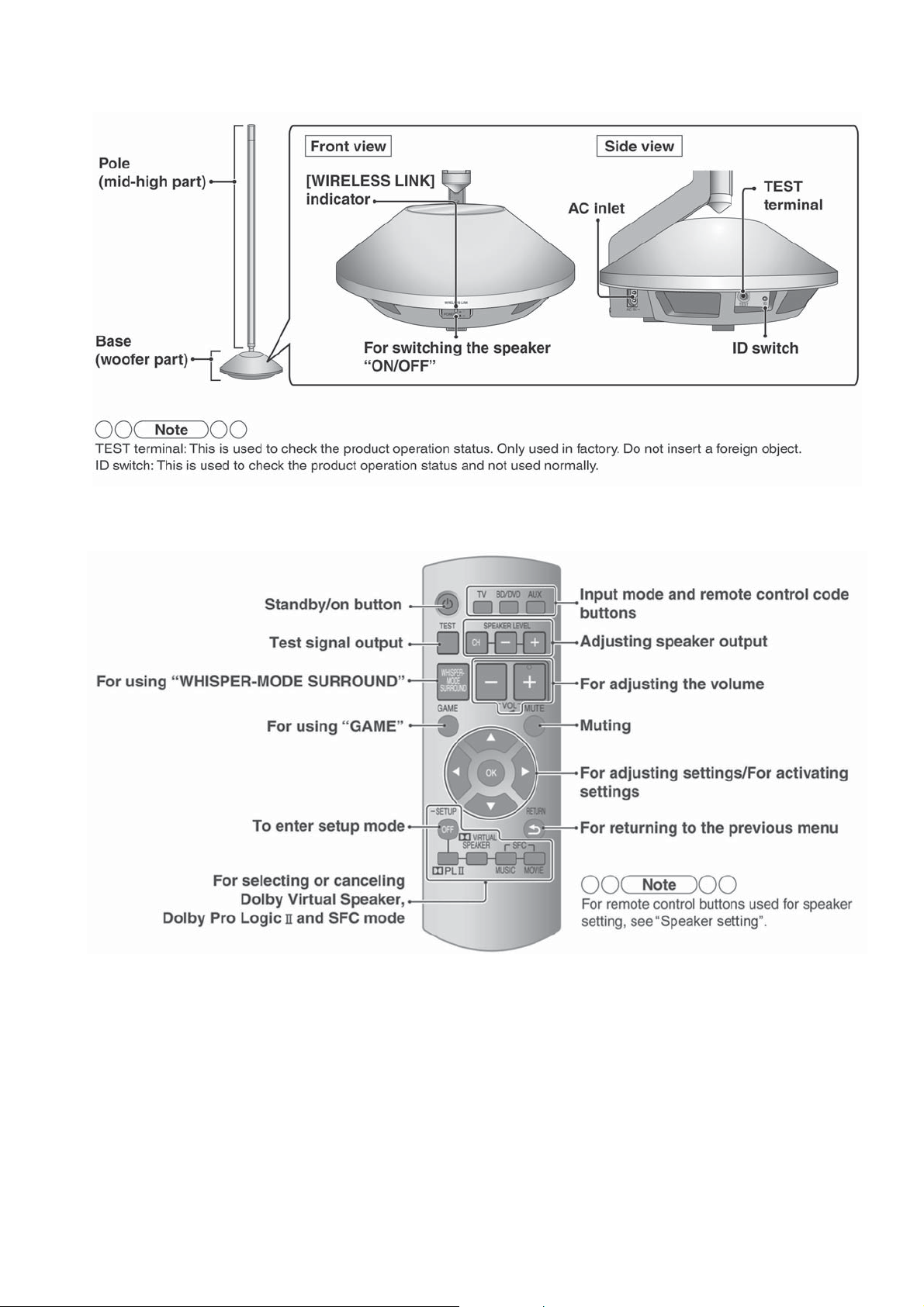
5.2. Speaker Unit (SB-ZT1/2)
5.3. Remote Control
11
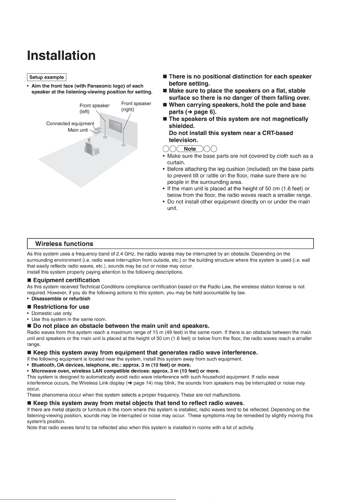
6Installation
12
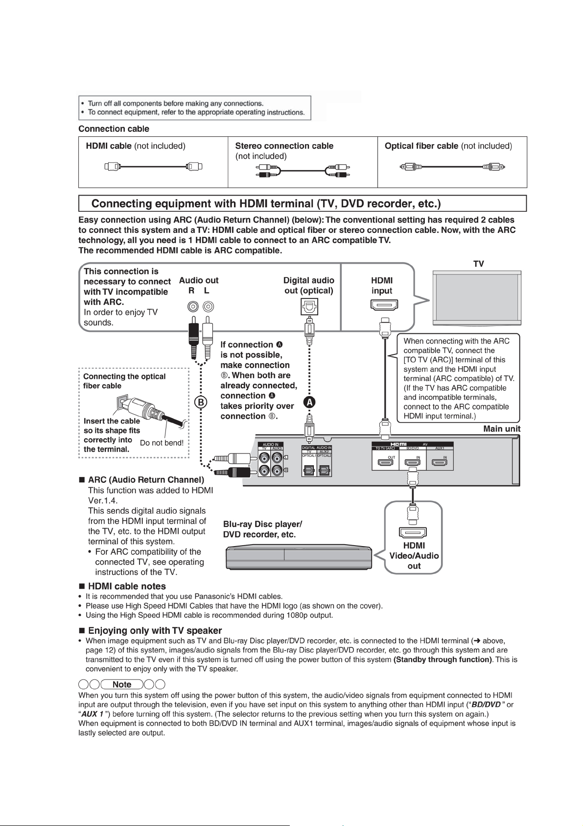
6.1. Basic Connections
6.1.1. Connecting equipment with HDMI terminal (TV, DVD recorder, etc.)
13
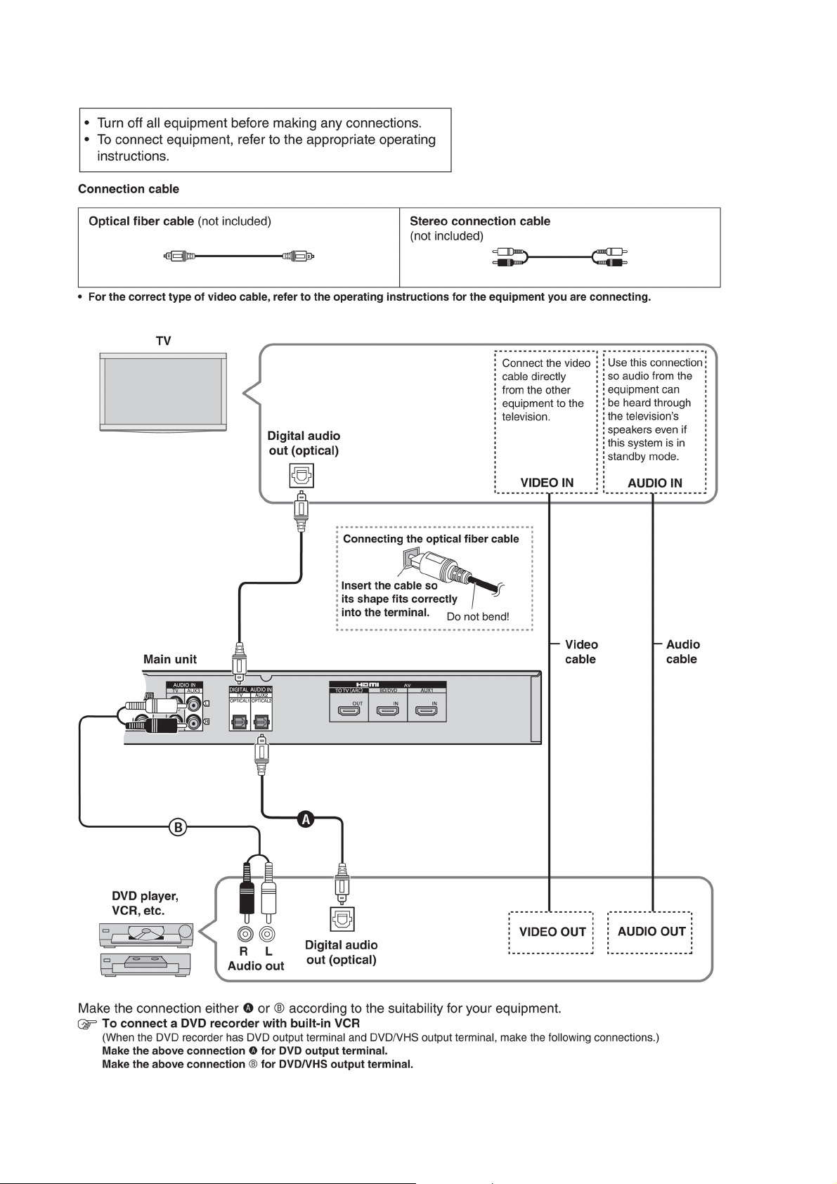
6.1.2. Connecting equipment without HDMI terminal (DVD player, VCR, etc.)
14
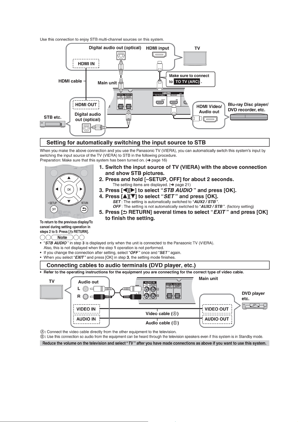
6.1.3. Connecting STB etc. and audio terminals (DVD player, etc.)
15
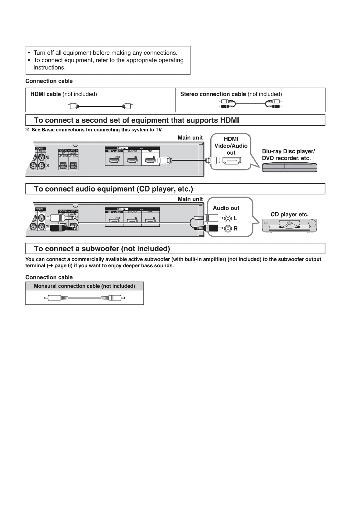
6.1.4. Other connections
16
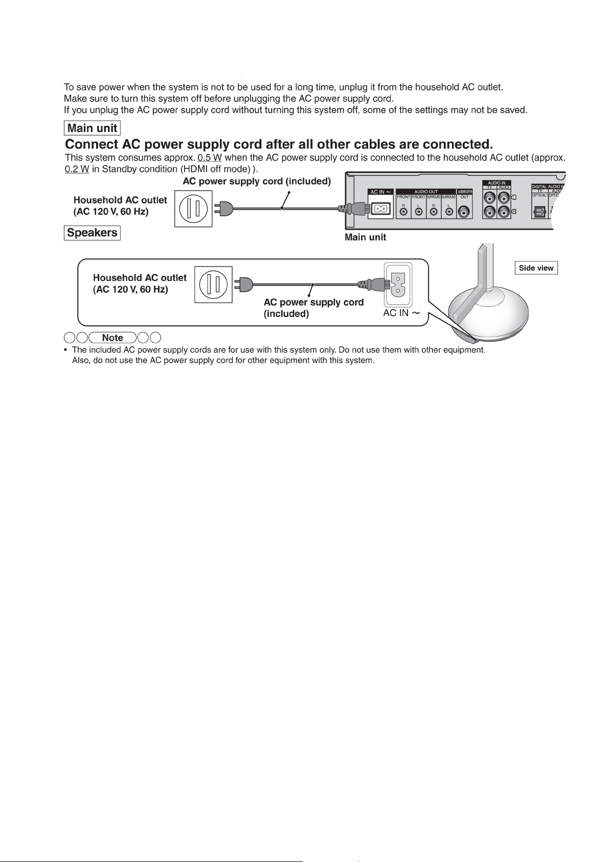
6.2. AC power supply connection
17
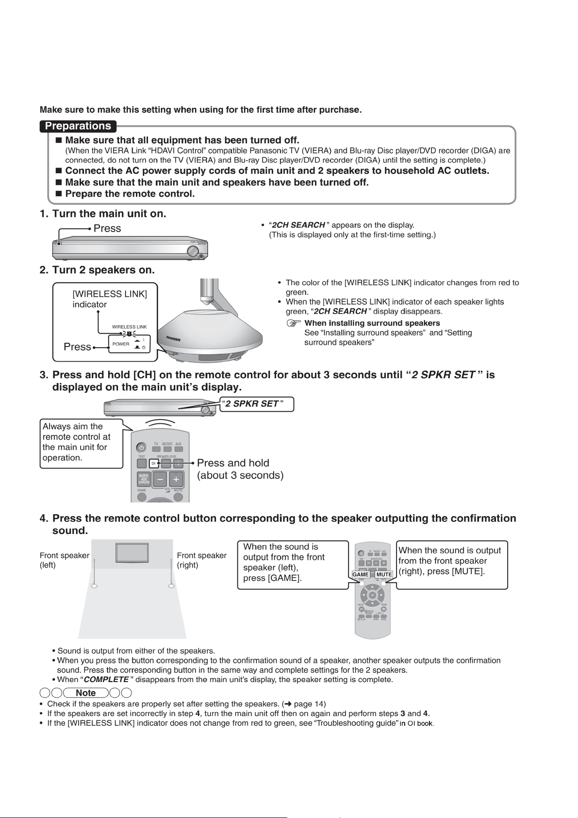
7 Speaker setting (SB-ZT1/2)
7.1. Setting the speakers (Front and Surround speakers)
18
19
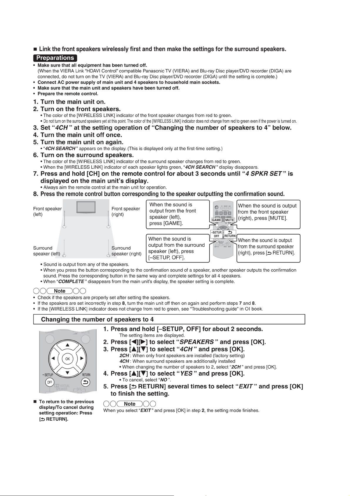
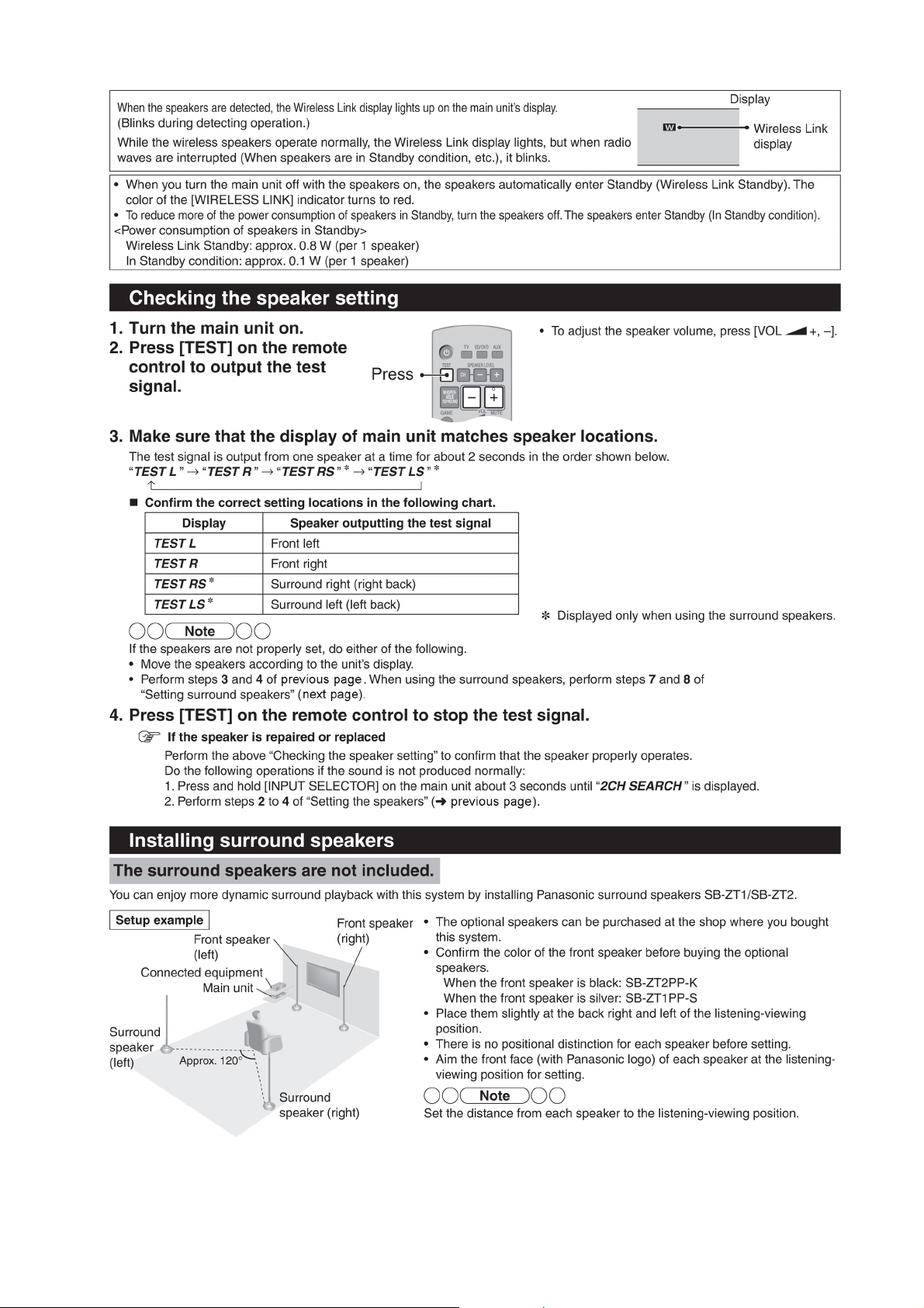
7.2. Setting surround speakers
20
7.3. Initialize the Speaker Setting
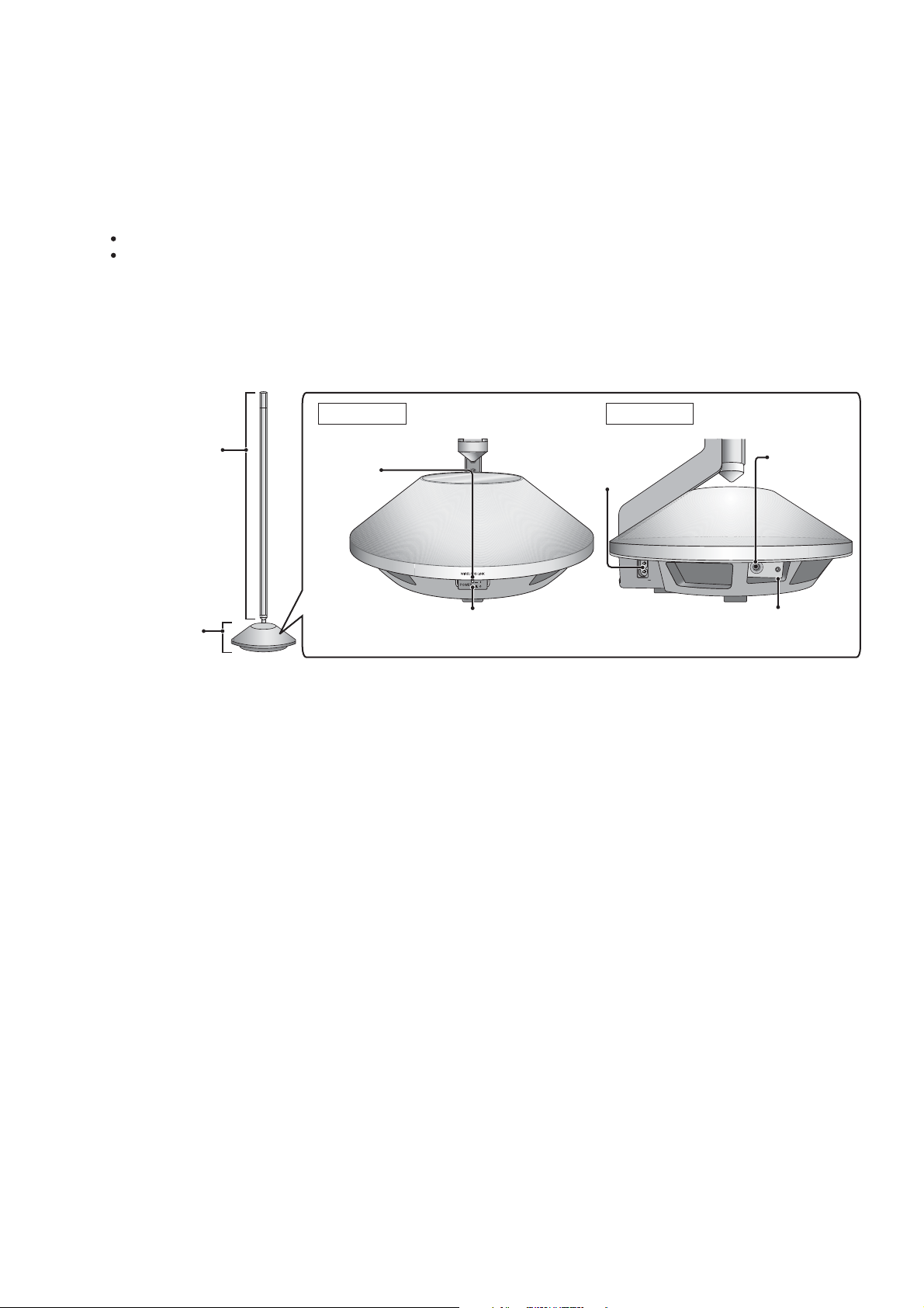
AC IN
TEST
ID
Pole
(mid-high part)
Base
(woofer part)
AC inlet
TEST
terminal
[WIRELESS LINK]
indicator
ID switch
For switching the speaker
“ON/OFF”
Front view
Side view
About the method of initializing the setting of the speaker.
Please initialize it when the main body of the speaker is changed or it added.
Please set the speaker after ID is reset.
Preparation:
Please connect the power supply code of the speaker.
Please confirm the power supply of the speaker cuts.
1. It keeps pushing the power switch for about five seconds with ID switch pushed.
(ID is reset.)
2. Please turn off power of the speaker.
21
8 Self-diagnostic and special mode setting
This unit is equipped with the self-diagnostic display function, which alarms faulty operation with error code. Use this function during
servicing.
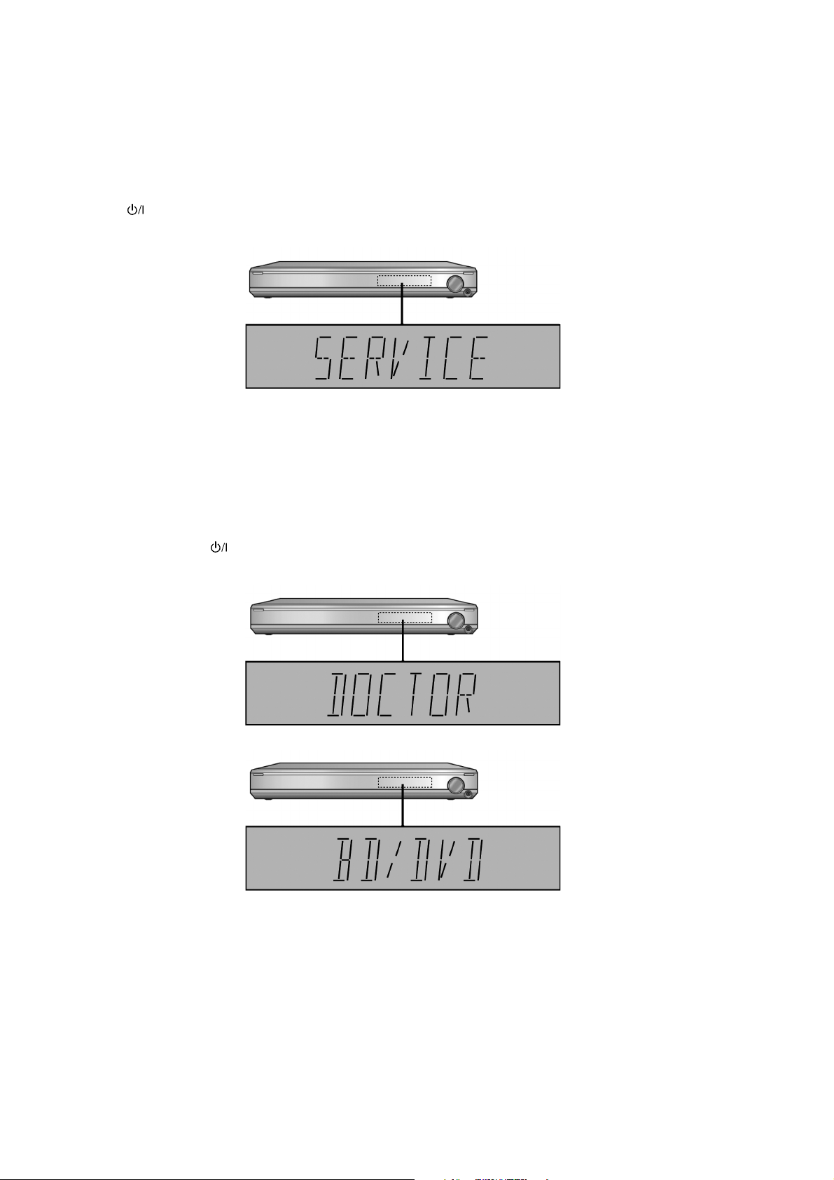
8.1. Activating Service Mode
This mode can be used during servicing.
1. Plug the AC adapter to the power source. Press and hold down the [VOL +] button and the [VOL -] button, and then press the
[POWER ] button at the same time.
2. The message, [SERVICE] appears on the display for three seconds, and then it will display the following. Refer to Fig. 1.
Fig. 1
3. To confirm the μP software version: When [VOL +] button is pressed, [M--- ****] is displayed [---] is current main micon version;
[****] is current checksum. If no ROM correction, [NO] is displayed.
When [VOL -] is pressed, display [H***], [***] is current version of HDMI micon.
8.2. Activating Doctor Mode
This mode can be used during servicing.
1. Plug the AC adapter to the power source. Press and hold down the [INPUT SELECTOR] button and the [VOL +] button, and
then press the [POWER ] button at the same time.
2. The message, “_DOCTOR_” appears on the display for three seconds, and then it will display the following. Refer to Fig. 2.
Fig. 2
8.3. Error Codes Display List
An error code automatically appears on the display (LCD) when faulty operation is detected. Refer to Fig. 3.
22
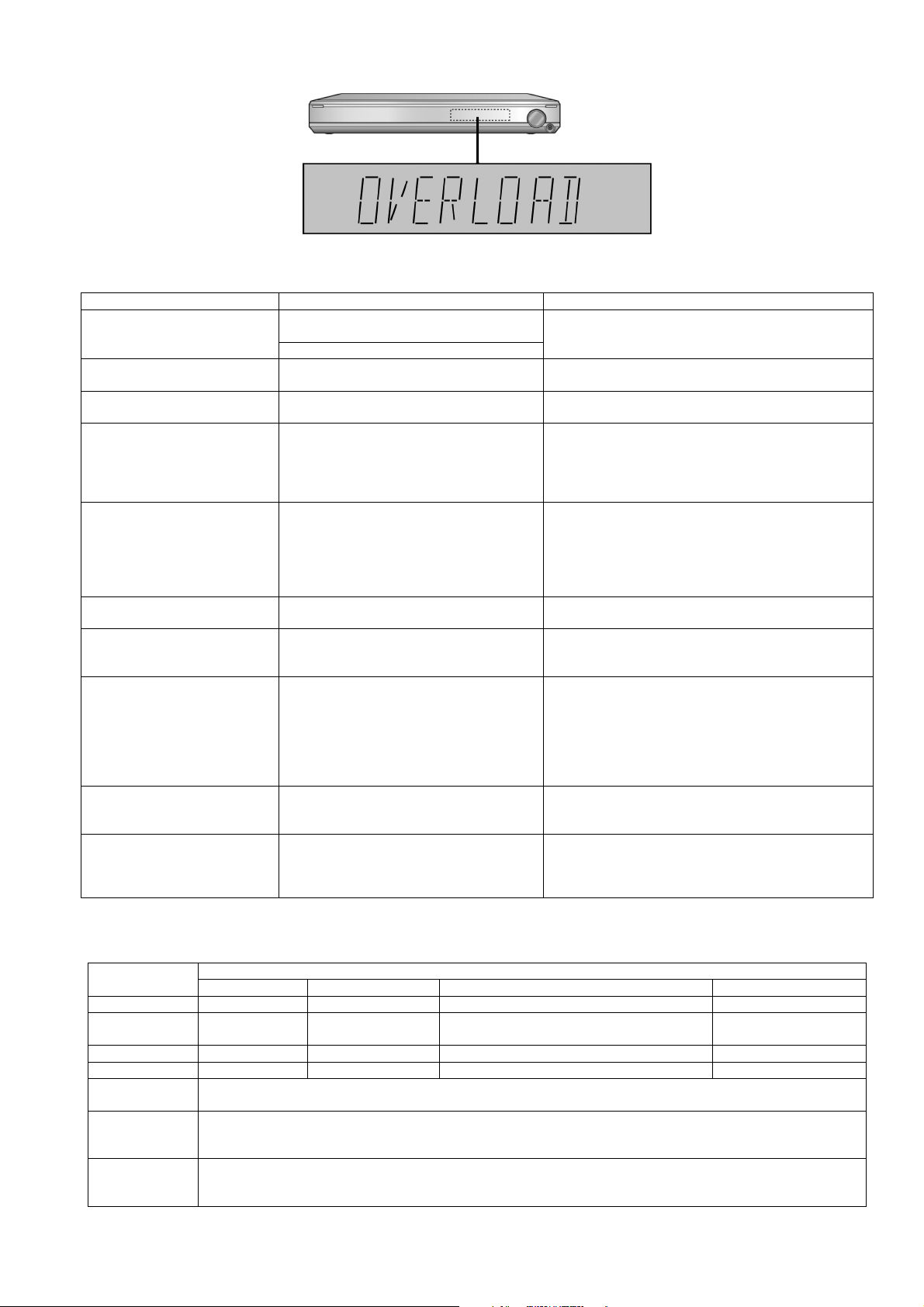
Fig. 3
FL display Symptom Cause and Remedy
F61/OVERLOAD Speaker short, amplifier failure, electrical over-
load etc.
Humidity protection activated
FANLOCK Fan stopped Failure fan and fan control circuits. Check for faulty parts
F70 Communication error between sub micro- pro-
F76 When the power is turned on, the unit power
Remote 2
Remote 1
U701 HDMI does not work properly. The equipment connected by the HDMI cable is not com-
U704 HDMI does not work properly. The system is receiving video signals that are incompatible
U703 A problem has occured with the HDMI connec-
NOT POSSIBLE FOR THIS INPUT
SOURCE
(Scrolling)
NOT POSSIBLE FOR THIS PCM
SOURCE
(Scrolling)
cessor and its peripheral LSI
automatically turns off; the power cannot be
turned on.
Main unit code setting problem with remote
control.
tion.
Input signals are automatically cancelled. You cannot use Dolby Virtual Speaker, Dolby Pro Logic II
Input signals are automatically cancelled. You cannot use Dolby Virtual Speaker, Dolby Pro Logic
Speaker short and failure in power amplifier, pre-amplifier
circuits. Check for faulty parts and replace with new parts if
necessary.
and replace with new parts if necessary.
Failure sub-micro processor and its peripherals LSI. Check
for faulty parts and replace with new parts if necessary.
Failure in the power circuit system of the unit. This may
happen when the direct current electricity is supplied to
speaker terminals. Check that the speaker wires are not
shorted (bare wire touching each other) or that the unit is in
a hot enviroment without proper ventillation.
Set the same remote control code for this system and
remote control.
• If “REMOTE 2” is displayed, set remote control code to
“2”.
• If “REMOTE 1” is displayed, set remote control code to
“1”.
patible with this system’s copyright protection technology.
with it through HDMI connection. Check the settings of the
connected equipment.
A problem has occurred with the HDMI connection. Try the
following to correct the problem. Consult your dealer if the
error code remains on the display.
• Turn the connected equipment off and on again.
• Disconnect the HDMI cable then reconnect it.
• Do not connect more than 2 equipment in series to the
output of this system.
and SFC for dual sounds.
and SFC effect with PCM signals with sampling frequency
over 48 kHz.
SFC is not available for multi-channel LPCM signal.
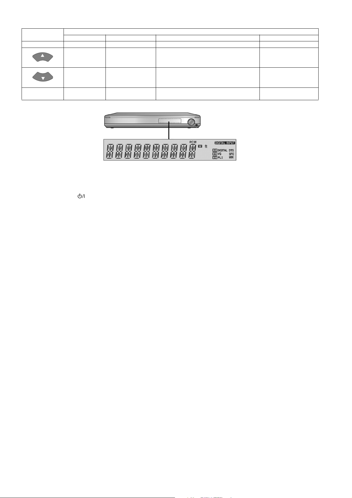
8.4. Inspection Mode
Remote Control Test Mode Function and settings
Selector Sound Mode Other settings Vol/Tone
SPEAKE LEVEL - AUX 4 STEREO Analog -18dB/0dB
SPEAKER LEVEL
CH
ENTER(OK) TV STEREO Digital (OPT1) -48dB/0dB
SFC MUSIC AUX 2 STEREO Digital (E2 : CAOX, Others : OPT2) -48dB/0dB
MUTE All indicators of FL are displayed. All LED are off.
VOL + Check Main μP software version.
VOL - Check HDMI uP software Version.
AUX 3 STEREO E2 : OPT2, Others : Analog -18dB/0dB
Note: After this setting, only “POWER” button or “Checker Command” code by the remote control can be entered.
Display [M---- ****]; ---- is current version; **** is current checksum. If no ROM correction, [NO] is displayed.
* Volume is still increased but not displayed.
Display [H---- ^^^^^]; ---- is current version.
* Volume is still increased but not displayed.
23
Remote Control Test Mode Function and settings
Selector Sound Mode Other settings Vol/Tone
TEST AUX 4 (Analog) — All CH output mode -18dB/0dB
TV (OPT1) STEREO Balance is set to leftmost. -18dB/0dB
TV (OPT1) STEREO Balance is set to rightmost. -18dB/0dB
VIRTUAL
SPEAKER
AUX 4 (Analog) DVS (REF <-> WIDE) Switch alternately -18dB/0dB
Fig. 4
8.5. Returning to Normal Display
1. Press the [POWER ] button on the unit to exit the function. The power is turned off.
24
9 Troubleshooting
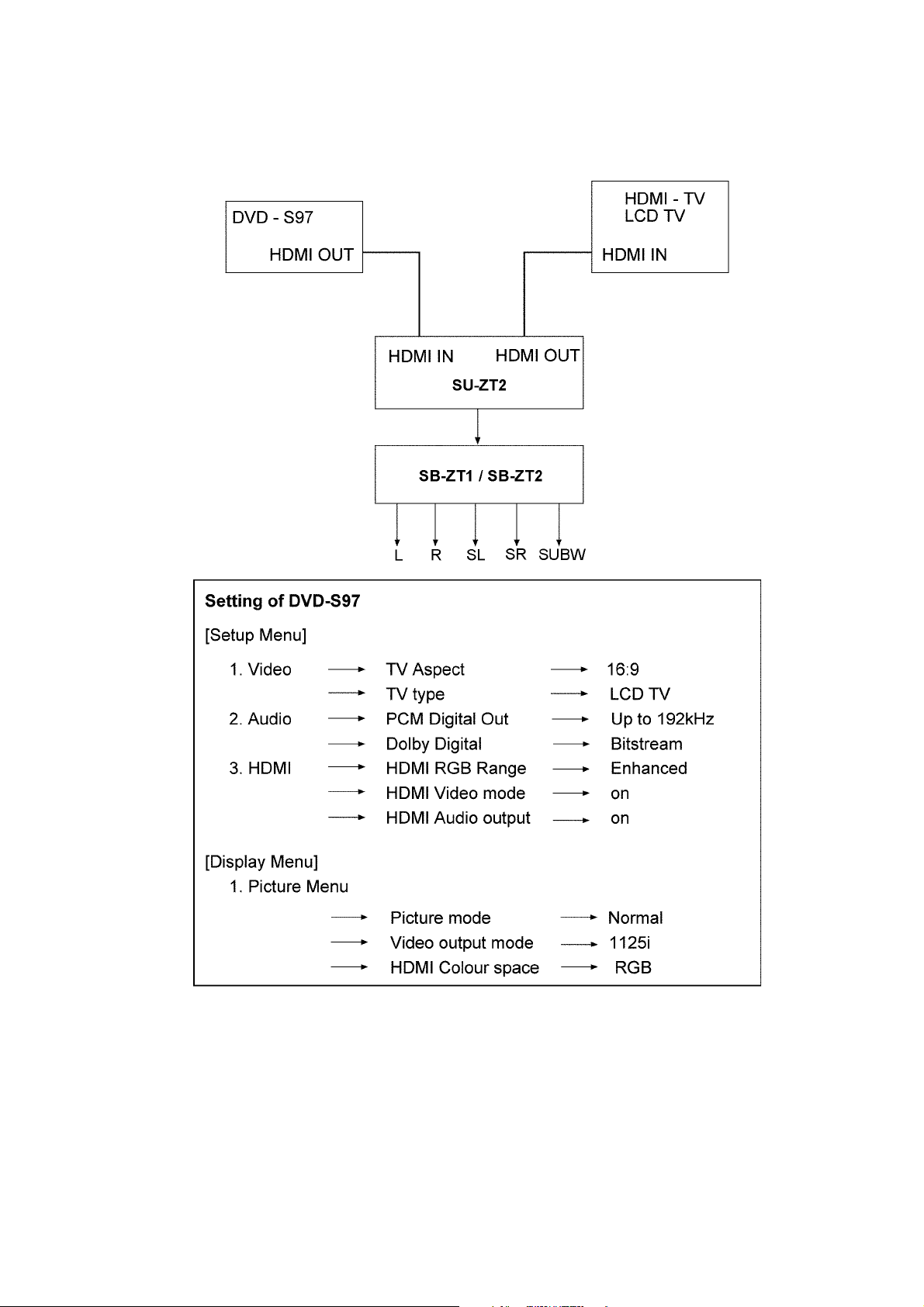
9.1. HDMI Checking Method
1. Connection of HDMI system
2. Check of HDMI Sound
a. Using the [DVD AUDIO TEST DISC V-612] and DVD-VIDEO disc with Dolby Digital signal.
b. [DVD AUDIO TEST DISC V-612] - Track No. 92 (96kHz, 5.1ch). Track No. 40 (Zero) Check the Level and Noise, output
from L / C / R / SL / SR / SW / speaker or pin.
c. [DVD AUDIO TEST DISC V-612] - Track No. 7 (192kHz, 2ch)
if this source can be reproduced, it is OK.
3. Check of HDMI Picture
a. The picture quality of TV is checked by watching that using [DVD TEST DISK S-20] or DVD disc with the colour bar signal.
b. [DVD TEST DISK S-20] - Track No. 2 (Flag of the rising sun)
[Colour bar disc] - Colour bar signal.
c. Make on DVD Setup Picture
25

Comfirmed that there are neither distortion nor a noise on the screen.
• If it is a picture quality equal when DVD was connected directly to TV, it is OK
1. Connect directly DVD player to TV.
2. Connect DVD player to set then connect it to TV.
3. Do the comparison for (1) and (2) if same, it is OK.
26
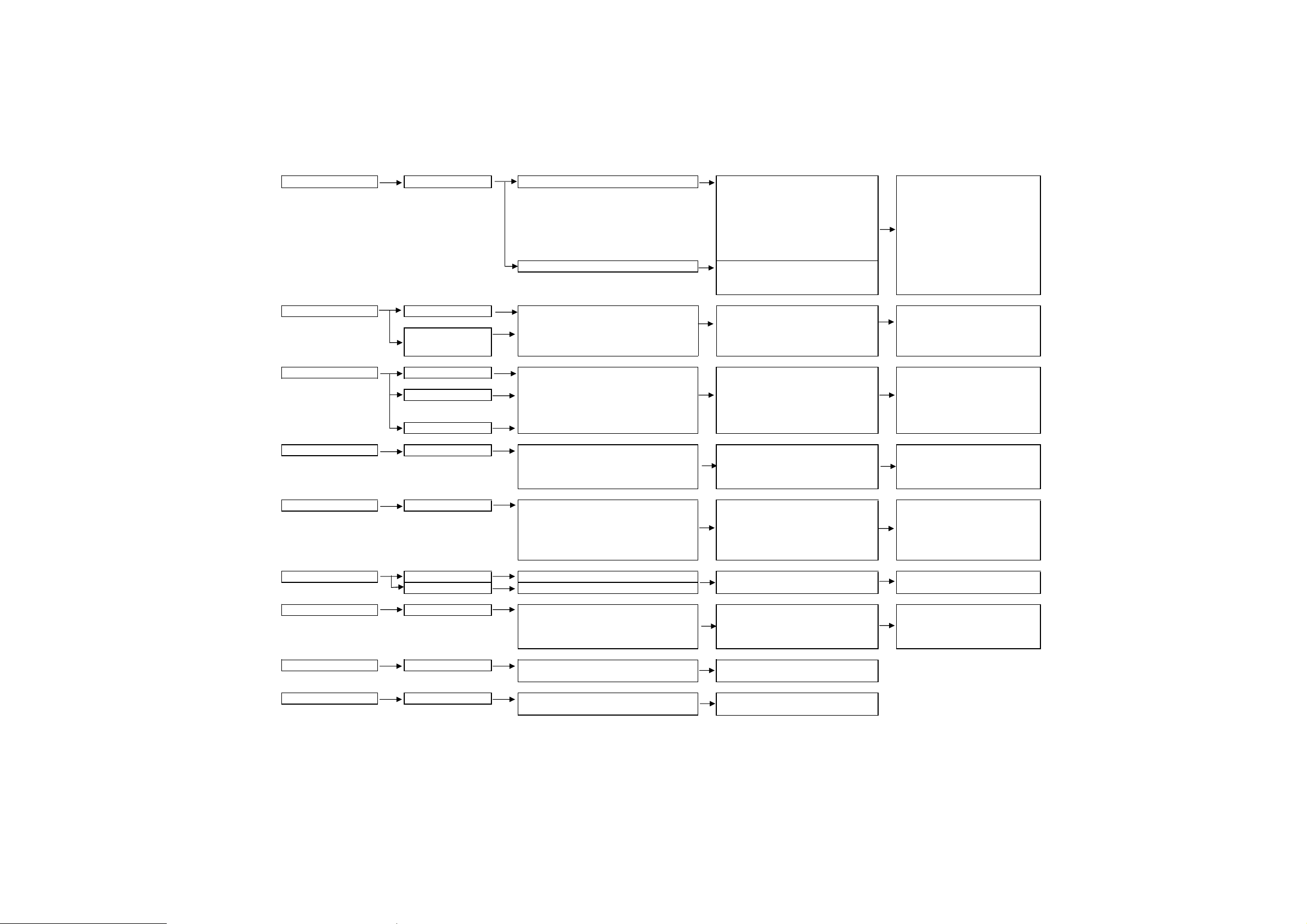
9.2. Troubleshooting Flow Chart
Power Supply
No power supply Primary Fuse (F701㧕check
Power source checking
Operation Switch No Operation
Operation Failure
HDMI Input No Picture
No Audio
HDMI Error appears
Optical Input No Audio
Audio Input No Audio
HDMI Output No picture Same as HDMI Input check
No audio Same as Audio output check
Audio Output No audio
Output (SW㧕
㧕
No audio
Headphone Output No audio
Audio output signal checking
ޓJK4003, JK4004, JK4005, JK4006
Headphone Output signal chec
k
ޓCN4601 ĺ JK4611
Main P.C.B chec
k
ޓIC4001, IC4304
SW output signal check
ޓJK4002
Main P.C.B chec
k
ޓIC4001, IC4303
Main P.C.B chec
k
ޓDSP output㧦IC4201㨪IC4203
ޓSelector Volume IC㧦IC4001
ޓAudio am
p
IC㧦IC4301, IC430
2
Wireless output line
ޓCN4701 ĺ Tx Module P.C.B
ޓMicro-processor IC㧦IC8001
Same as Audio Output check Same as Audio output check
Main P.C.B Chec
k
Selector
IC㧦IC4001
DSP P.C.B check
ޓIC1000, IC1001
ConnectorFFC checking
ޓOptical Input Jack㧦JK4501, JK4502
ޓCN4102 ĺ CN1002
Main P.C.B
ޓMicro-processor IC㧦IC8001
Main P.C.B
ޓMicro-processor IC㧦IC8001
Main P.C.B Check
ޓIC4001, IC4101, IC4102
ޓCN4101 (Pin 25,26),( Pin 28,29)
DSP P.C.B Check
ޓIC1000, IC1001
Power supply check (For audio circuit)
ޓ
ޓ
+7V㧦Q5507, -7V㧦Q5508
Input terminal signal checking
(JK4001ĺ
IC4001 Pin ԛԜԟԠ)
Switch P.C.B Check㧦S4601 ĺ
ޓޓޓޓMain P.C.B㧦IC8001-Pin 81
Main P.C.BޓPower circuit check
ޓD5502㧦Pin Ԙ,ԙ
ޓIC5501㧦Pin ԛ,Ԝ,ԟ
ޓIC5502㧦Pin Ԙ,Ԛ
ޓPC5501㧦Pin Ԙ,ԙ
Power Supply line checking:
ޓD5505 ĺ IC5571㧦Pin Ԙ
Main P.C.B
ޓMicro-processor IC
㧦IC8001
ޓReset IC 㧦IC8003
ޓPower Det IC㧦IC8004
Panel P.C.B Check
ConnectorFFC checking
Main P.C.B check
ޓFL Power Supply T5551㧦Pin
Ԛ,Ԝ,ԟ,Ԡ
ޓFFC connector (CN4601)
Main P.C.B
ޓMicro-processor IC㧦IC8001
HDMI Power Supply Checking
ޓJW4205 ĺ CN2005
ޓIC5561, IC5562, IC5563 (Main P.C.B)
ConnectorFFC checking
ޓCN2003, CN2004, CN4221
HDMI P.C.B Check
ޓIC2101, IC2201, IC2232
ޓHDMI Micro-processor IC:IC2002
DSP P.C.B Check
ޓIC1000, IC1001
Main P.C.B
ޓMicro-processor IC㧦IC8001
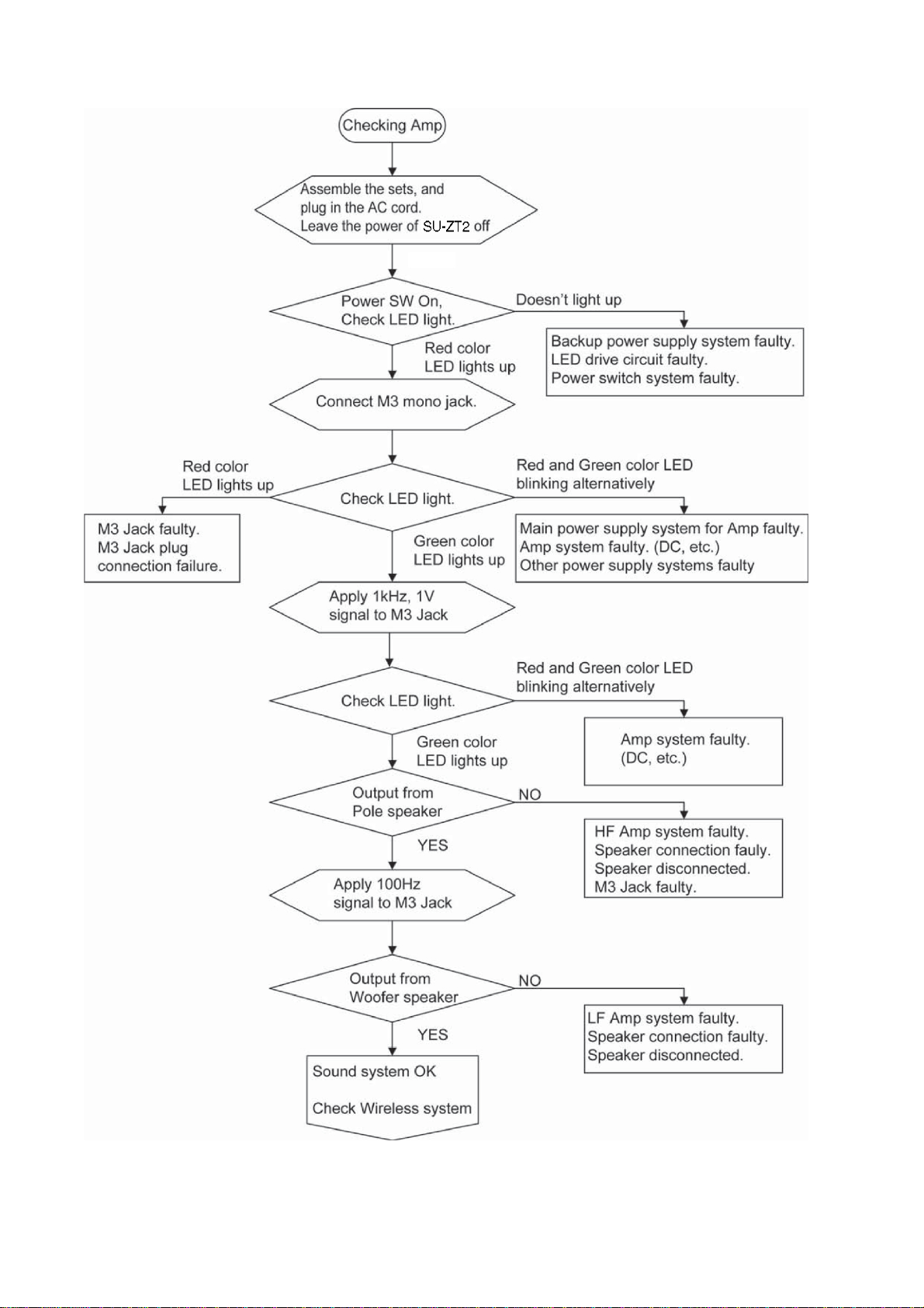
9.2.1. Main Unit (SU-ZT2)
27
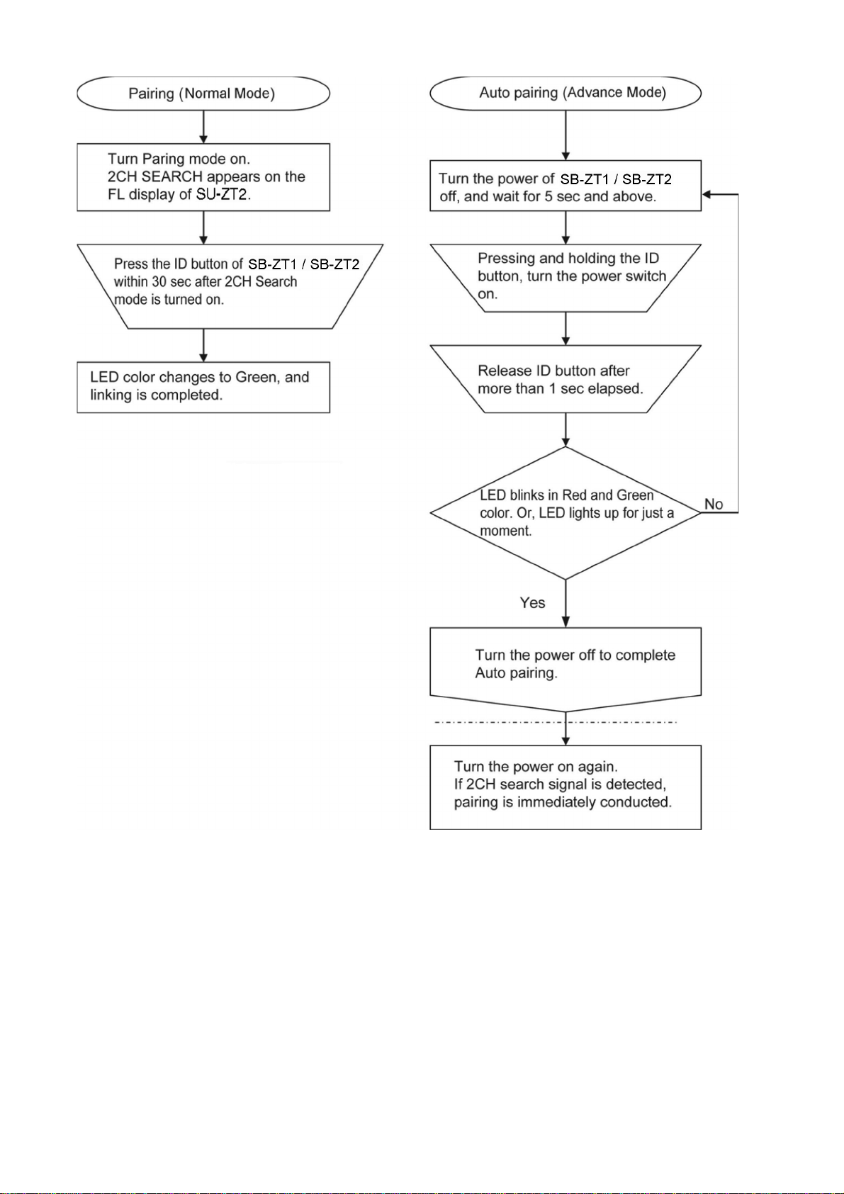
9.2.2. Speaker Unit (SB-ZT1/2)
28
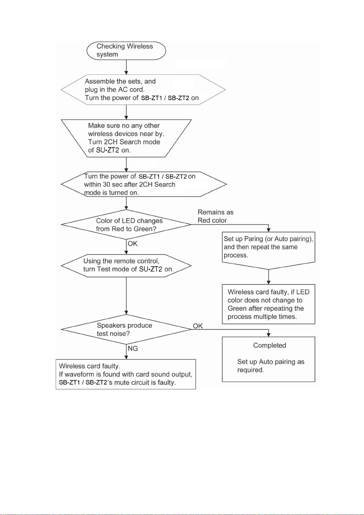
9.2.3. Speaker Unit (SB-ZT1/2) - Wireless Link
29
30
 Loading...