

T
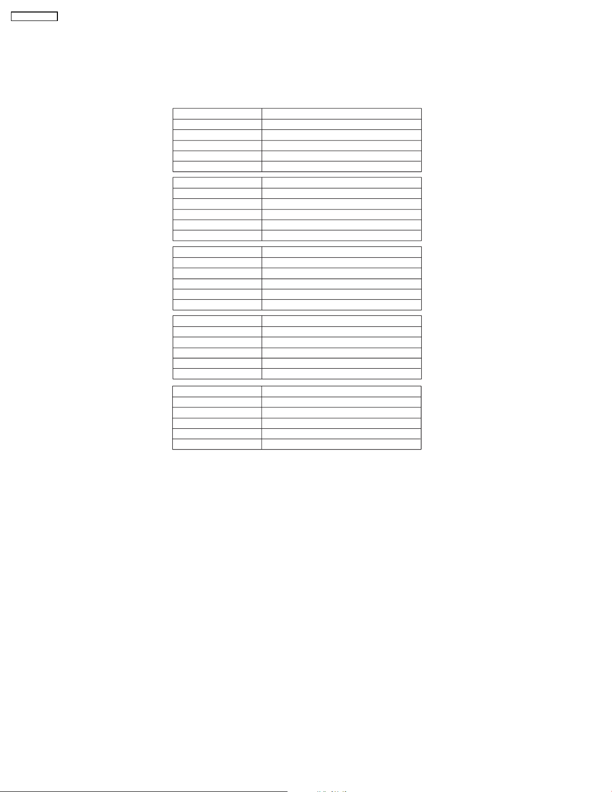
Specification
ORDER NO. MD0707037CE
Speaker System
SB-WVK860GC
SB-VK860GC
Colour
(K)... Black Type
ype 1 way, 2 speaker system (Bass reflex)
Speaker unit(s) Impedance 3 Ω
1. Woofer 16 cm Aluminum Cone type
2. Woofer 16 cm Aluminum Cone type
Input power (IEC) 110 W* (Max)
Output sound pressure 86 dB/W (1.0 m)
Frequencyrange 26 Hz to 310 Hz (-16 dB)
30 Hz to 250 Hz (-10 dB)
Dimensions (W x H x D) 200 mm x 429.5 mm x 359 mm
Mass 6.1 kg
Notes :
1. Specifications are subject to change without notice.
Mass and dimensions are approximate.
2. Total harmonic distortion is measured by the digital spectrum
analyzer.
* Rating with low-cut filter equipped amplifier.
© 2007 Matsushita Electric Industrial Co. Ltd.. All
rights reserved. Unauthorized copying and
distribution is a violation of law.
SB-WVK860GC
1 System Combination
1.1. System Breakdown
Note :
The tables below show the breakdown for speaker combinations used in main unit systems.
System SC-VK860GC-K
Music center SA-VK860GC-K
Front speakers
Surround speakers
Center speaker
Subwoofer
System SC-VK860EE-K
Music center SA-VK860EE-K
Front speakers
Surround speakers
Center speaker
Subwoofer
System SC-VK860GCSK
Music center SA-VK860GCSK
Front speakers
Surround speakers
Center speaker
Subwoofer
System SC-VK860GN-K
Music center SA-VK860GN-K
Front speakers
Surround speakers
Center speaker
Subwoofer
SB-PF860GC-K
SB-PS860GC-K
SB-PC860GC-K
SB-WVK860GC-K
SB-PF860GC-K
SB-PS860GC-K
SB-PC860GC-K
SB-WVK860GC-K
SB-PF860GC-K
SB-PS860GC-K
SB-PC860GC-K
SB-WVK860GC-K
SB-PF860GC-K
SB-PS860GC-K
SB-PC860GC-K
SB-WVK860GC-K
System SC-VK860GS-K
Music center SA-VK860GS-K
Front speakers
Surround speakers
Center speaker
Subwoofer
SB-PF860GC-K
SB-PS860GC-K
SB-PC860GC-K
SB-WVK860GC-K
1.2. Packaging information (SB-VK860GC-K)
Note: For more information on the complete packaging condition for speakers in SB-VK860GC-K, please refer to section 4.3 in
service manual of SB-PF860GC-K (Order no. MD0707036C E).
2
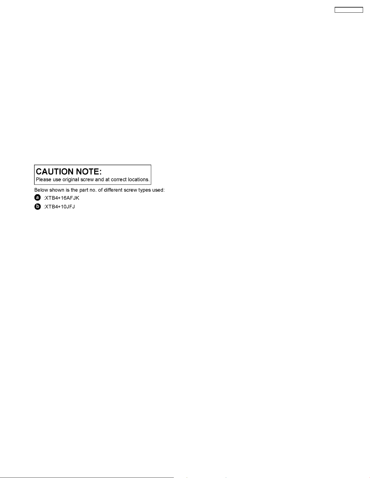
2 Assembling and Disassembling
“ATTENTION SERVICER”
Some chassis components may have sharp edges. Be careful when disassembling and servicing.
1. This section describes procedures for checking the operation and replacing the main components.
2. For reassembly after operation checks or replacement, reverse the respective procedures.
Special reassembly procedures are described only when required.
3. Select items from the following index when checks or replacement are required.
4. Refer to the Parts No. on the page of “Parts Locatio n and Replacement Parts List” (Section 5), if necessary.
Below is the list of disassembly sections
• Disassembly of Front Panel assembly
• Disassembly of Woofer 1 (SP1)
• Disassembly of Woofer 2 (SP1)
• Disassembly of Woofer 1 spacer
• Disassembly of Woofer 2 spacer
SB-WVK860GC
3
SB-WVK860GC
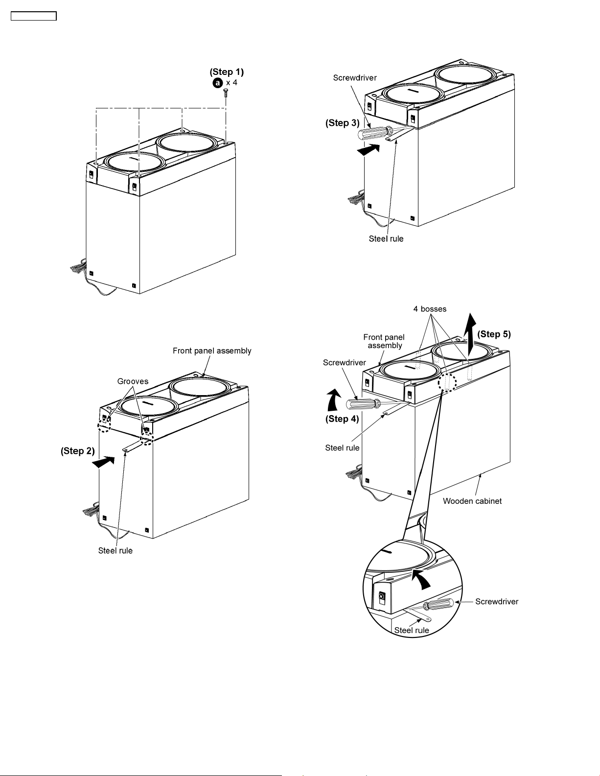
2.1. Disassembly of Front panel assembly
Step 3: Insert a flathea d screwdriver into the groove as shown.
Ensure that the screwdriver is above the steel rule.
Step 1: Remove 4 screws.
Step 2: Insert a small steel rule into the grooves of the front
panel assembly and lift up to make a gap allowance between
the front panel assembly and wooden cabinet as arrow shown.
Step 4: Apply light force along the sides of wooden cabinet to
push up the front panel assembly.
Step 5: Remove front panel assembly.
Caution:
Do not exert strong force as it may damage front panel
assembly.
4
 Loading...