

Panasonic SBWA-935-EE Service manual
Active Subwoofer System
SB-WA935EE
Colour
(S)... Silver Type
ORDER NO. MD0504115C3
Specification
n Active subwoofer
Type 1 way, 2 speaker system, Bass reflex
Speaker unit(s)
1. Woofer 15 cm Cone type
2. Woofer 15 cm Cone type
Output sound pressure 84 dB/W (1.0 m)
Frequency range 34 Hz-220 Hz (-16 dB)
38 Hz-190 Hz (-10 dB)
Dimensions (W x H x D) 202 x 410 x 500 mm
Mass 13.7 kg
n General
Power consumption 390 W
Power supply AC 230V, 50Hz
Note :
Specifications are subject to change without notice.
Mass and dimensions are approximate.
n System : SC-HT935(EE)
Music Center: SA-HT935(EE)
Satellite Speakers: SB-HT880(EB)
Active Subwoofer: SB-WA935(EE)
CONTENTS
Page Page
1 Safety Precautions
1.1. GENERAL GUIDELINES
2 Handling the Lead-free Solder
2.1. About lead free solder (PbF)
3 Before Repair and Adjustment
3
4 Protection Circuitry 4
3
5 Connection of the Speaker Cables
6 Disassembly Procedure
4
4
4
6.1. Disassembly flow chart
© 2005 Matsushita Electric Industrial Co. Ltd.. All
rights reserved. Unauthorized copying and
distribution is a violation of law.
5
6
6

SB-WA935EE
6.2. Disassembly of the Speaker Unit and Checking of the
P.C.B.
7 Voltage Measurement and Waveform Chart
7.1. Voltage Measurement
7.2. Waveform Chart
8 Block Diagram
9 Notes of Schematic Diagram
10 Schematic Diagram
10.1. Power Circuit
10.2. Transformer Circuit and AC Inlet Circuit
10.3. Amplifier Circuit
11 Printed Circuit Board
8
14
14
15
16
17
18
18
20
21
11.1. Power P.C.B.
11.2. AC Inlet P.C.B. and Transformer P.C.B.
11.3. Amplifier P.C.B.
12 Wiring Connection Diagram
13 Illustration of ICs, Transistors and Diodes
14 Parts Location and Replacement Parts List
14.1. Cabinet
14.2. Electrical Parts List
14.3. Packing Materials & Accessories Parts List
14.4. Packaging
22
22
24
25
26
27
28
29
32
35
35
2
SB-WA935EE
1 Safety Precautions
1.1. GENERAL GUIDELINES
1. When servicing, observe the original lead dress. If a short circuit is found, replace all parts which have been overheated or
damaged by the short circuit.
2. After servicing, ensure that all the protective devices such as insulation barriers, insulation papers shields are properly installed.
3. After servicing, check for leakage current to prevent from being exposed to shock hazards.
1.1.1. LEAKAGE CURRENT COLD CHECK
1. Unplug the AC cord and connect a jumper between the two prongs on the plug.
2. Using an ohmmeter measure the resistance value, between the jumpered AC plug and each exposed metallic cabine t part on
the equipment such as screwheads, connectors, control shafts, etc. When the exposed metallic part has a return path to the
chassis, the reading should be between 1MΩand 5.2Ω.
When the exposed metal does not have a return path to the chassis, the reading must be
.
Fig. 1
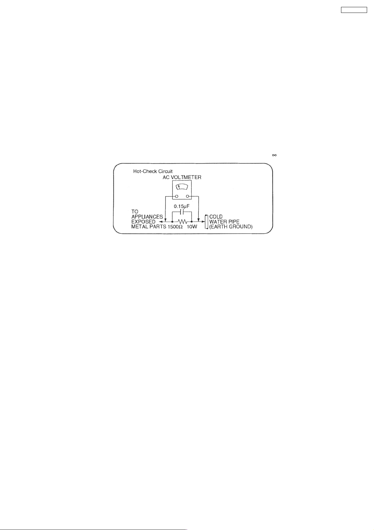
1.1.2. LEAKAGE CURRENT HOT CHECK (See Figure 1.)
1. Plug the AC cord directly into the AC outlet. Do not use an isolation transformer for this check.
2. Connect a 1.5kΩ, 10 watts resistor, in parallel with a 0.15µF capacitors, between each exposed metallic part on the set and a
good earth ground such as a water pipe, as shown in Figure 1.
3. Use an AC voltmeter, with 1000 ohms/volt or more sensitivity, to measure the potential across the resistor.
4. Check each exposed metallic part, and measure the voltage at each point.
5. Reverse the AC plug in the AC outlet and repeat each of the above measurements.
6. The potential at any point should not exceed 0.75 volts RMS. A leakage current tester (Simpson Model 229 or equivalent) may
be used to make the hot checks, leakage current must not exceed 1/2 milliamp. Should the measurement is outside of the limits
specified, there is a possibility of a shock hazard, and the equipment should be repaired and rechecked before it is returned to
the customer.
3

SB-WA935EE
2 Handling the Lead-free Solder
2.1. About lead free solder (PbF)
Distinction of PbF P.C.B. :
P.C.B.s (manufactured) using lead free solder will have a PbF stamp on the P.C.B.
Caution:
Pb free solder has a higher melting point than standard solder. Typically the melting point is 50 -
·
Please use a high temperature soldering iron. In case of the soldering iron with temperature control, please set it to 700 ± 20°F
(370 ± 10°C).
· Pb free solder will tend to splash when heated too high (about 1100°F/600°C).
· W hen soldering or unsoldering, please completely remove all of the solder on the pins or solder area, and be sure to heat the
soldering points with the Pb free solder until it melts enough.
70°F (30 - 40°C) higher.
3 Before Repair and Adjustment
Disconnect AC power, discharge Power Supply Capacitors C601~C604 through a 10 Ω, 1 W resistor to ground.
DO NOT SHORT-CIRCUIT DIRECTLY (with a screwdriver blade, for instance), as this may destroy solid state devices.
After repairs are completed, restore power gradually using a variac, to avoid overcurrent.
Current consum ption at AC 230 V, 50 Hz in NO SIGNAL mode should be ~1000 mA.
4 Protection Circuitry
The protection circuitry may have operated if either of the following conditions are noticed:
· No sound is heard when the power is turned on.
· Stops during a performance.
The function of this circuitry is to prevent circuitry damage if, for example, the positive and negative speaker connection wires are
“shorted”, or if speaker systems with an impedance less than the indicated rated impedance of the amplifier are used.
If this occurs, follow the procedure outlines below:
1. Turn off the power.
2. Determine the cause of the problem and correct it.
3. Turn on the power once again after one minute.
Note:
When the protection circuitry functions, the unit will not operate unless the power is first turned off and then on again.
4
SB-WA935EE
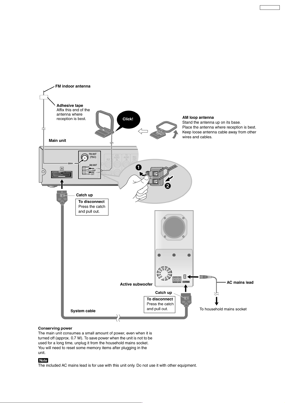
5 Connection of the Speaker Cables
· Be sure to connect speaker cables before connecting the AC power supply cord.
· The load impedance of any speaker used with this unit must be 4Ω.
· Be sure to connect the cable from the right speaker to the right terminal and the cable from the left speaker to the left terminal.
1. Strip off the outer covering, and twist the center conductor. Make sure the bare ends of the wires are not unravelled. (If they are,
twist them tight again.)
2. Insert the wire to the rear panel of the unit and close the lever.
5
SB-WA935EE
6 Disassembly Procedure
“ATTENTION SERVICER”
Some chassis components may have sharp edges.
Be careful when disassembling and servicing.
1. This section describes procedures for checking the operation of the major printed circuit boards and replacing the
main components.
2. For reassembly after operation checks or replacement, reverse the respective procedures.
Special reassembly procedures are described only when required.
3. Select items from the following index when checks or replacement are required.
· Disassembly of the Front Panel Unit
· Disassembly of Woofer Speaker Unit 1
· Disassembly of Woofer Speaker Unit 2
· Disassembly of the Power Amp Unit
· Disassembly of the Rear Panel and Fan Unit
· Disassembly and checking of the AC Inlet P.C.B. and Amplifier P.C.B.
· Disassembly and checking of the Power P.C.B. and Transformer P.C.B.
· Replace ment of Power ICs and Transistors
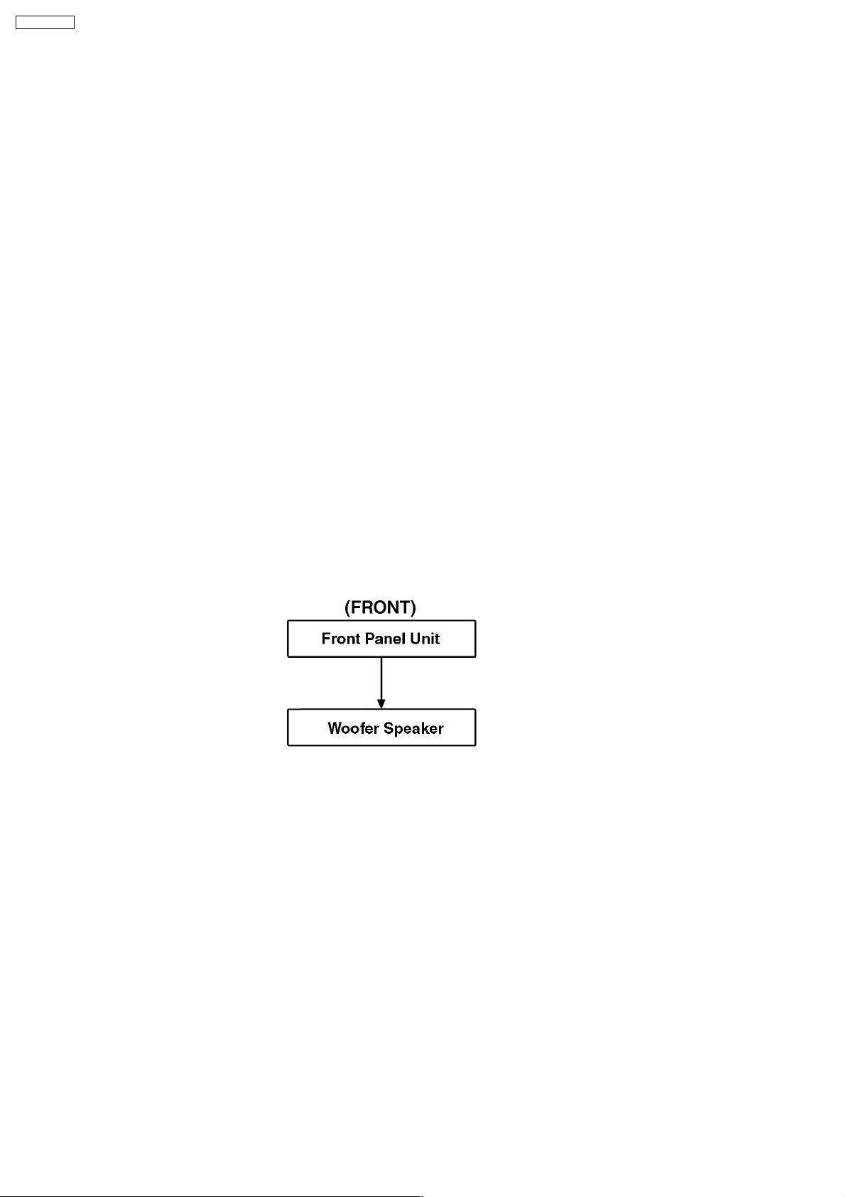
6.1. Disassembly flow chart
The following chart is the procedure for disassembling the casing and inside parts for internal inspection when carrying out the
servicing.
To assemble the unit, reverse the steps shown in the chart below.
6.1.1. Disassembly of Front Panel Assembly
6
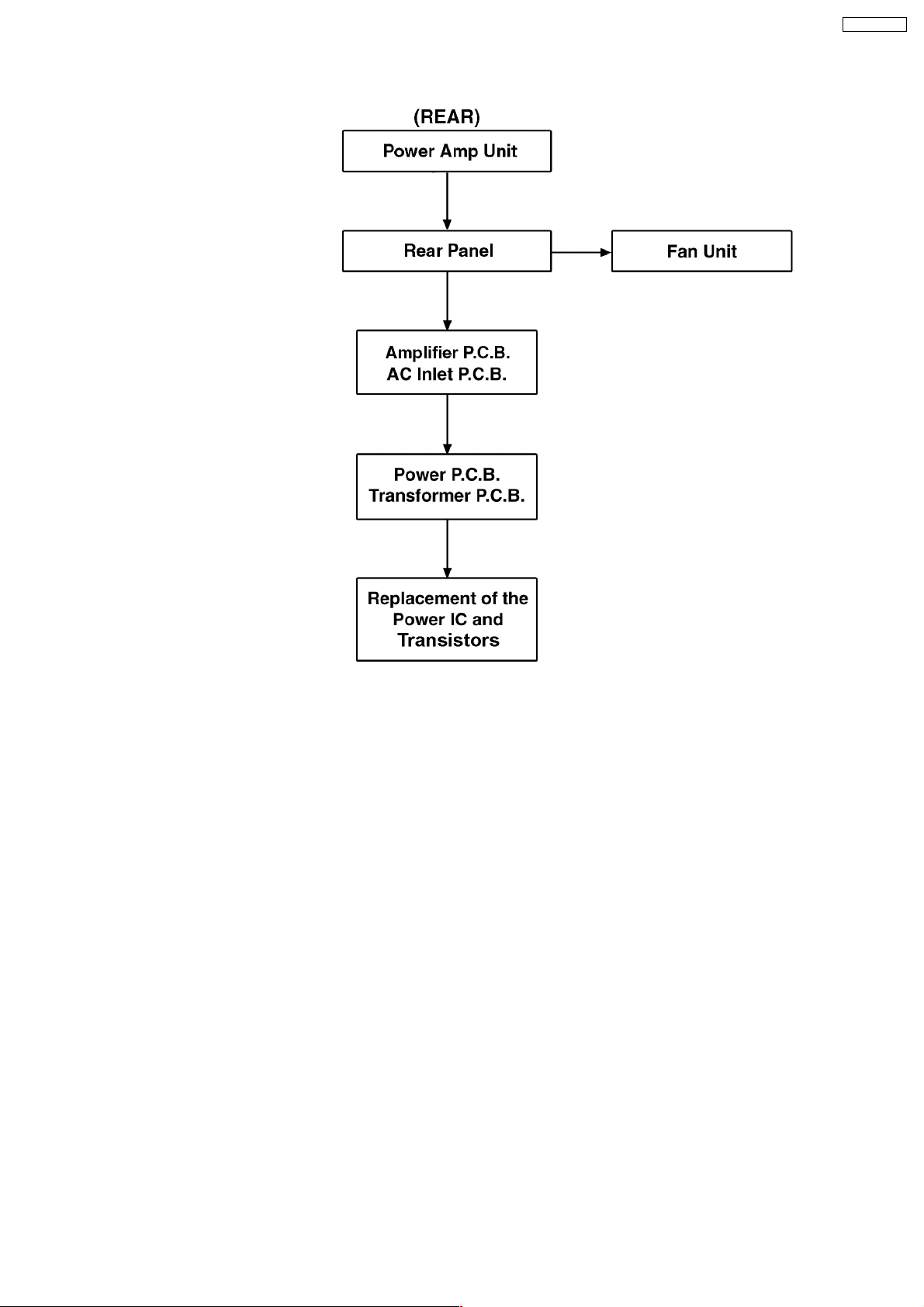
6.1.2. Disassembly of Rear Assembly
SB-WA935EE
7
SB-WA935EE
6.2. Disassembly of the Speaker Unit and Checking of the P.C.B.
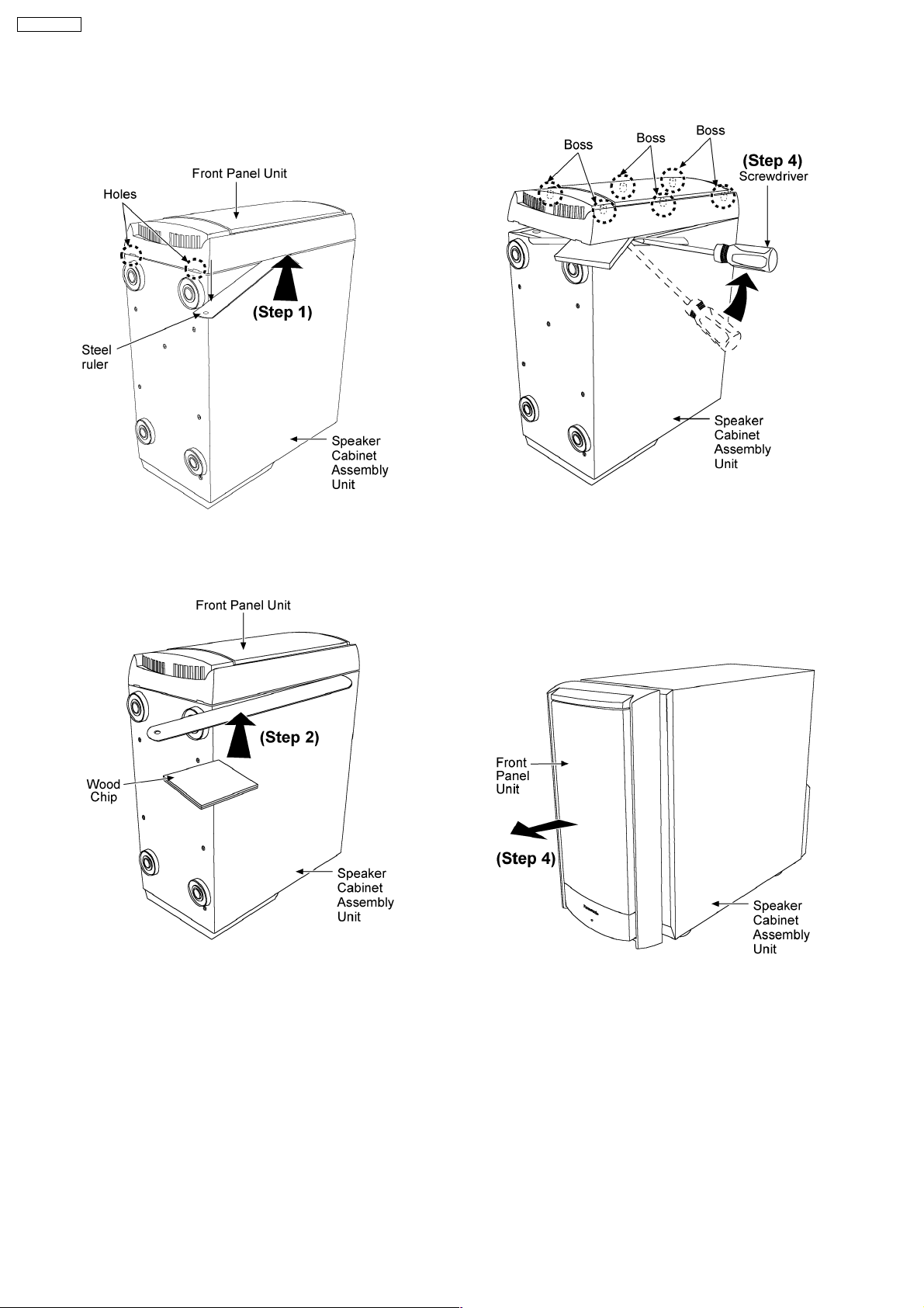
6.2.1. Disassembly of the Front Panel
Unit
Step 1: Slot in a steel ruler to give a gap between the Front
Panel Unit and the Speaker Cabinet Assembly as arrow shown.
Steps 2: Slot a piece of wood chip in between the Front Panel
Unit and the steel ruler as arrow shown.
Step 3: Use the screwdriver to slightly lift up the Front Panel
Unit as arrow shown.
Note:
Be careful with the bosses which are glued to the Speaker
Cabinet Assembly Unit.
Step 4: Remove the Front Panel Unit from the Speaker
Cabinet Assembly Unit as arrow shown.
8
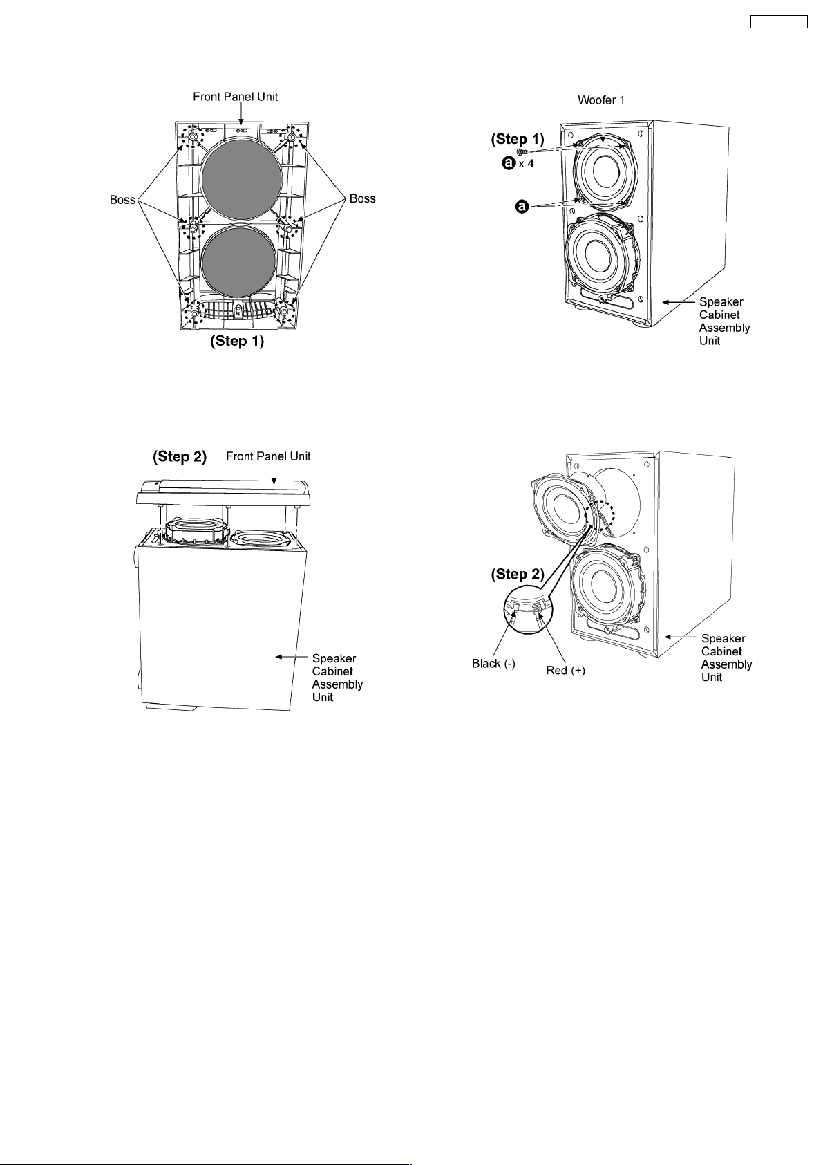
· Assembly of the Front Panel Unit.
Step 1: Clean up the remaining glue at the 6 bosses points
and replace with the normal glue.
SB-WA935EE
Step 1: Remove 4 screws.
Step 2: Replace the Front Panel Unit firmly back to the
Speaker Cabinet Assembly Unit.
6.2.2. Disassembly of the Woofer
Speaker 1
Follow Step (1) to Step (4) described in section 6.2.1.
Step 2: Remove the Woofer 1 by detaching the (+) red and (-)
black wires.
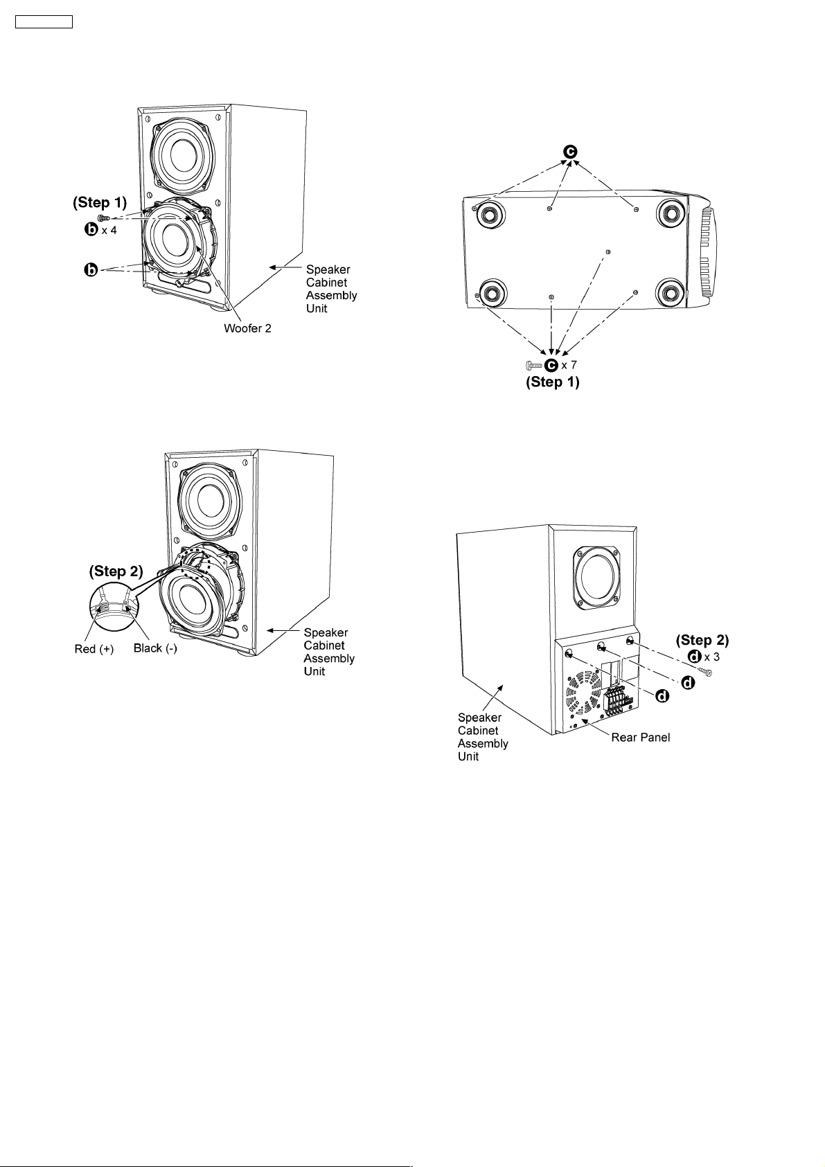
6.2.3. Disassembly of the Woofer
Speaker 2
Follow Step (1) to Step (4) described in section 6.2.1.
9
SB-WA935EE
Step 1: Remove 4 screws.
6.2.4. Disassembly of the Power Amp
Unit
Step 2: Remove the Woofer 2 by detaching the (+) red and (-)
black wires.
Step 1: Lay the speake r unit as shown. Remove 7 screws from
the bottom of the Speaker Cabinet Assembly Unit.
Step 2: Remove 3 screws from the rear panel.
10
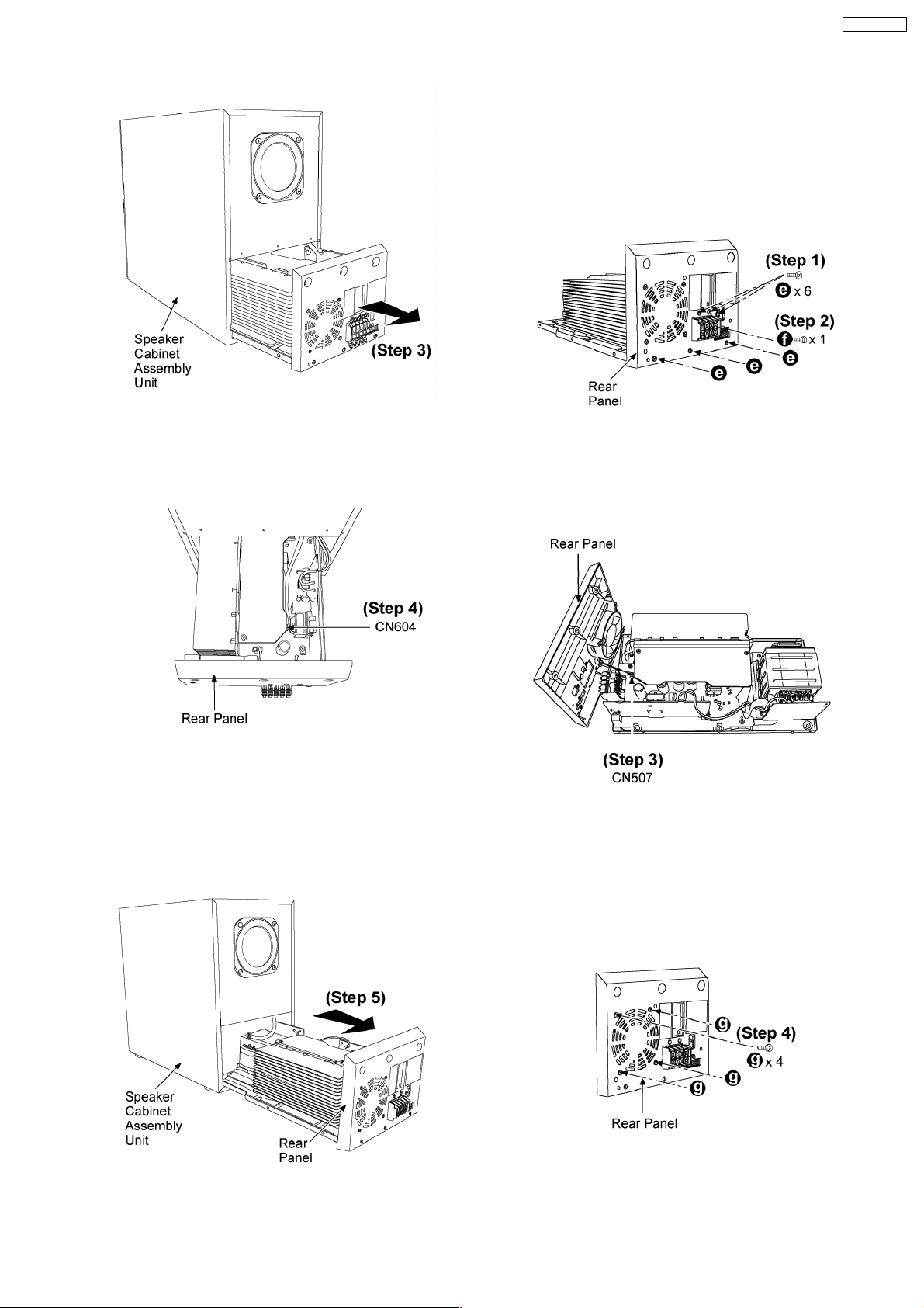
Step 3: Pull out the Power Amp Unit slightly as arrow shown.
SB-WA935EE
6.2.5. Disassembly of the Rear Panel and
Fan Unit
Follow Step (1) to Step (5) described in section 6.2.4.
Step 4: Disconnect the connector (CN604).
Steps 1 & 2: Remove 6 screws from the rear panel.
Step 3: Disconnect the connector (CN507) to detach the rear
panel.
Step 5: Pull out the entire Power Amp Unit.
Step 4: Remove 4 screws from the rear panel.
11
 Loading...