

Panasonic SAXR-55-PC Service manual
Specification
n AMPLIFIER SECTION
Rated minimum sine wave RMS power output
20 Hz-20 kHz both channels driven
0.09 % total harmonic distortion
1 kHz continuou s power output both channels driven
0.09 % total harmonic distortion 105 W per channel
Total harmonic distortion
rated power at 20 Hz-20 kHz 0.09 % (6 Ω)
Power bandwidth
both channels driven, -3 dB 4 Hz-88 kHz
Power output each channel driven
0.9 % total harmonic distortion at 1kHz
Front (L/R) 100 W (6 Ω)
Center 100 W (6 Ω)
Surround (L/R) 100 W (6 Ω)
Surround Back (L/R) 100 W (6 Ω)
Load impedance
Front (L/R)
Aor B
A and B
BI-WIRE 6-8 Ω
Center
Surround (L/R) 6-8 Ω
Surround Back (L/R) 6-8 Ω
Frequency response
CD, TAPE, TV, DVD, DVD RECORDER,
VCR1, VCR2
DVD 6CH 4 Hz-44 kHz, ±3 dB
100 W per channel
(6 Ω,0.9%)
4 Hz-88 kHz, ±3 dB
(6 Ω)
(6 Ω)
6-8 Ω
6-8 Ω
6-8 Ω
ORDER NO. MD0504178C1
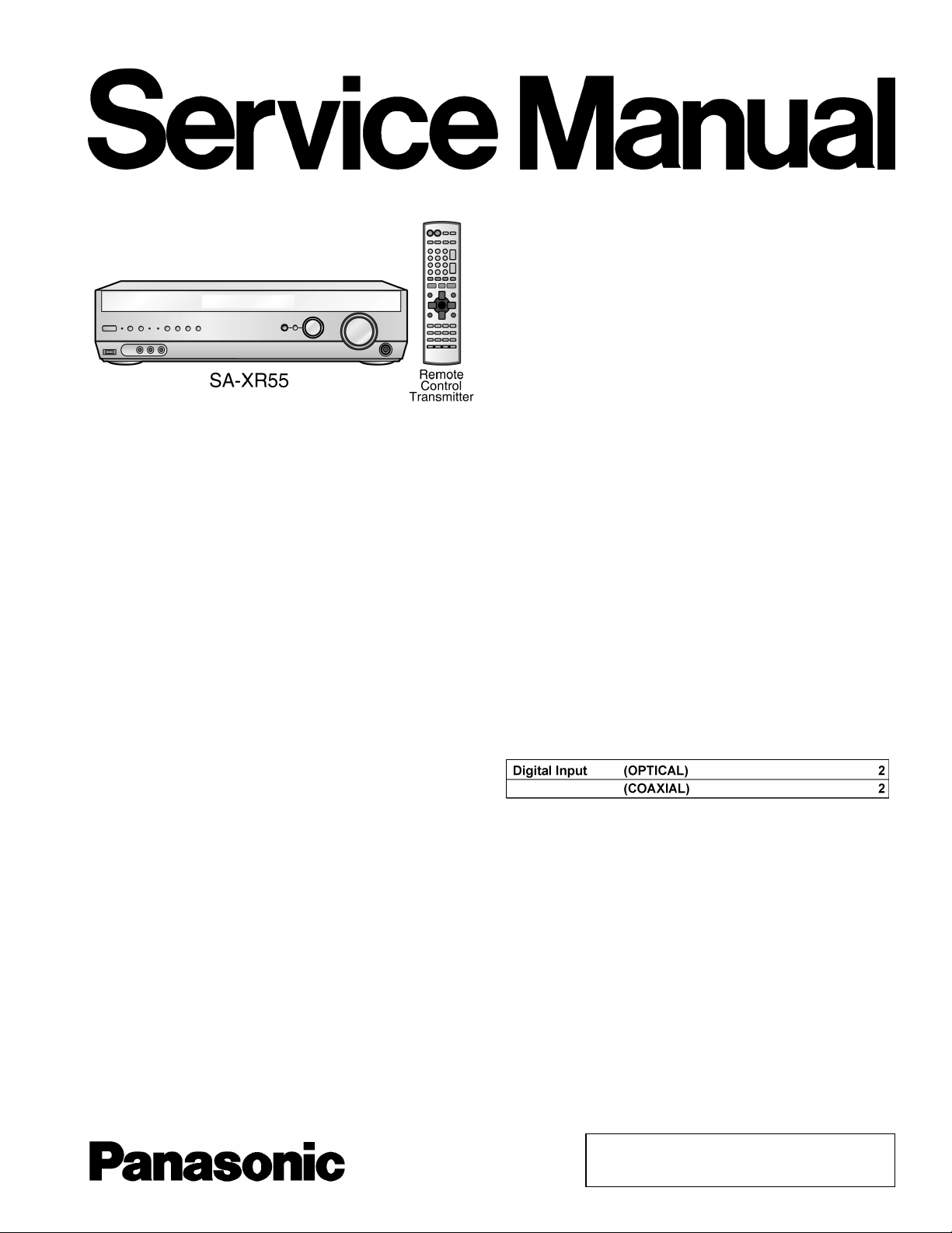
AV Control Receiver
SA-XR55P
SA-XR55PC
Colour
(S)...............Silver Type
(K)...............Black Type (P only)
Input sensitivity
CD, TAPE, TV, DVD, DVD RECORDER,
VCR1, VCR2
Input impedance
CD, TAPE, TV, DVD, DVD RECORDER,
VCR1, VCR2
S/N (IHF A)
CD, TV, DVD, DVD RECORDER
(Digital Input)
Tone controls
BASS
TREBLE
Subwoofer frequency response (-6 dB) 7 Hz-200 Hz
n FM TUNER SECTION
Frequency range
Sensitivity 11.2 dBf
50 dB quieting sensitivity
MONO 18.3 dBf
STEREO 38.3 dBf
Total harmonic distortion
MONO 0.2%
STEREO 0.3%
S/N
(200mV, IHF ’66)
(103 dB, IHF ’66)
50 Hz, +10 to -10 dB
20kHz,+10to-10dB
87.9-107.9 MHz
(4.5 µV, IHF ’58)
(45 µV, IHF ’58)
27 mV
22 kΩ
85 dB
(2 µV, IHF ’58)
A1
© 2005 Matsushita Electric Industrial Co. Ltd.. All
rights reserved. Unauthorized copying and
distribution is a violation of law.
SA-XR55P / SA-XR55PC
MONO 73 dB
STEREO 67 dB
Frequency response 20 Hz-15 kHz, +1 dB,
Alternate channel selectivity 65 dB
Capture ratio 1.5 dB
Image rejection at 98 MHz 40 dB
Spurious response rejection at 98 MHz 75 dB
AM suppression 50 dB
Stereo separation
1 kHz
10 kHz
Antenna terminal 75 Ω (unbalanced)
n AM TUNER SECTION
Frequency range 530-1710 kHz
Sensitivity 20 µV, 330 µV/m
Selectivity 55 dB
IF rejection at 1000 kHz 50 dB
n VIDEO SECTION
Output voltage at 1 V input (unbalanced) 1±0.1 Vp-p
Maximum input voltage
Input/output impedance
S-Video
-2 dB
40 dB
30 dB
1.5 Vp-p
75 Ω
Input TV, DVD, DVD
RECORDER
Output TV MONITOR
Component Video
Input TV, DVD, DVD
RECORDER
Output TV MONITOR
n GENERAL
Power supply AC 120 V, 60 Hz
Power consumption 135 W
Dimensions (W × H × D)
Mass 4.6 kg (10.1 lb.)
n DIN POWER
1 kHz, T.H. D 1%
Notes:
1. Specifications are subject to change without notice.
Mass and dimensions are approximate.
2. Total harmonic distortion is measured by the digital spectrum
analyzer.
430 mm × 107.5 mm ×
394 mm
(16-15/16” × 4-7/32” × 15-1/2”)
2 x 100 W (6 Ω)
CONTENTS
Page Page
1 SAFETY PRECAUTIONS 4
1.1. GENERAL GUIDELINES
2 Before Repair and Adjustment
3 Protection Circuitry
4 Handling the Lead-free Solder
4.1. About lead free solder (PbF)
5 Accessories
6 Operating Instructions
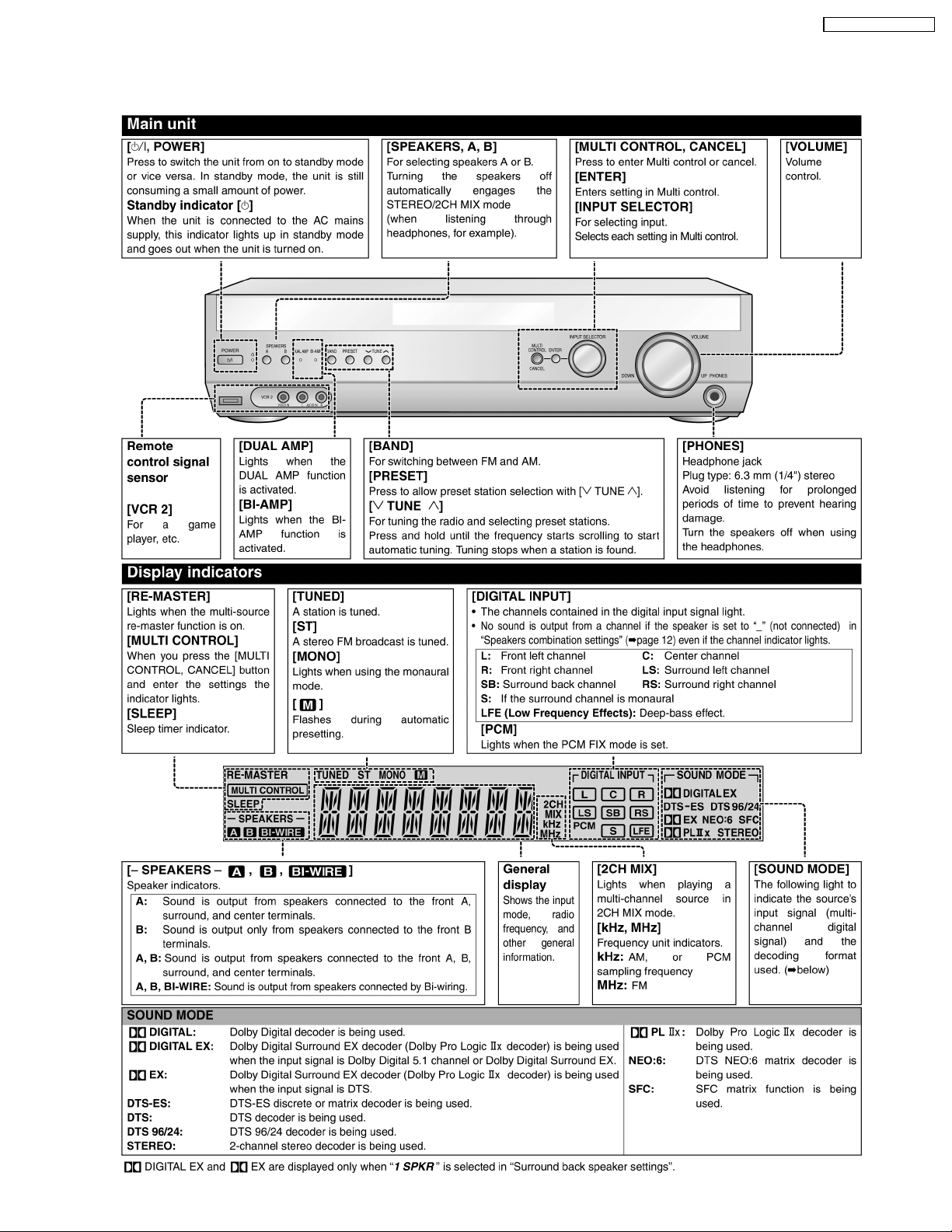
6.1. Main Unit
6.2. Remote Control
6.3. Home Theater Connections
6.4. Other Connections
7 Disassembly and Main Component Replacement Procedures
and Operational Check
7.1. Disassembly flow chart
7.2. P.C.B. Positions
7.3. Disassembly of Top Cabinet.
7.4. Checking for the DSP P.C.B. (Side A/B) and Main P.C.B.
(Side A).
14
17
17
18
18
19
4
5
5
5
5
6
7
7
8
9
7.5. Disassembly and Checking of Main P.C.B. (Side B)
7.6. Disassembly of Tuner Pack and Tuner Extent P.C.B.
7.7. Disassembly and Checking of Speaker P.C.B.
7.8. Disassembly and Checking of Component Video P.C.B.
7.9. Disassembly and Checking of Video & Optical P.C.B.
7.10. Disassembly of Rear Panel
7.11. Disassembly and Checking of Input P.C.B.
7.12. Disassembly of Front Panel
7.13. Disassembly and Checking of Panel P.C.B., Volume
P.C.B. and Headphone P.C.B.
7.14. Disassembly and Checking of Power P.C.B.
8 Self Diagnosis Display Function
8.1. Automatically Displayed Error Codes
8.2. Display Details
8.3. Returning to Normal Display
8.4. Overload/Shutdown Detection intenal Condition
8.5. Overload/Thermal Detection Display
8.6. Activating Self Diagnosis Function (Servicing Mode)
8.7. Analog 6.1 CH Output Check Method
20
20
21
21
22
22
23
24
25
26
27
27
27
27
27
27
27
28
2

8.8. Returning to Normal Display 28
8.9. Activating Self Diagnosis Function (Doctor Mode)
9 Voltage Measurement and Waveform Chart
9.1. Voltage Measurement
9.2. Waveform Chart
10 Block Diagram
11 Notes of Schematic Diagram
12 Schematic Diagram
12.1. DSP Circuit
12.2. Main Circuit
12.3. Input Circuit &Tuner Extent Circuit
12.4. Panel Circuit
12.5. Speaker Circuit, Headphone Circuit & Volume Circuit
12.6. Power Circuit
12.7. Video and Optical Circuit
12.8. Component Video Circuit
13 Printed Circuit Board
13.1. DSP P.C.B. (Side A & B)
28
30
30
37
39
51
52
52
57
75
80
82
83
87
90
13.2. Main P.C.B. (Side A & B)
13.3. Input P.C.B.
13.4. Tuner Extent P.C.B., Panel P.C.B. & Headphone P.C.B.
13.5. Volume P.C.B. & Speaker P.C.B.
13.6. Power P.C.B.
13.7. Video & Optical P.C.B. & Component Video P.C.B.
14 Wiring Connection Diagram
15 Type Illustration of ICエs, Transistors and Diodes
16 Terminal Function of ICs
16.1. IC6801 (C2BBGF000669): Microprocessor
17 Parts Location and Replacement Parts List
17.1. Cabinet Parts Location
17.2. Electrical Parts List
17.3. Packing Materials & Accessories Parts List
17.4. Packaging
91
SA-XR55P / SA-XR55PC
91
93
97
99
101
102
103
105
107
108
108
109
110
113
129
129
3
SA-XR55P / SA-XR55PC
1 SAFETY PRECAUTIONS
1.1. GENERAL GUIDELINES
1. When servicing. observe the original lead dress. If a short circuit is found, replace all parts which have been overheated or
damaged by the short circuit.
2. After servicing, see to it that all the protective devices such as insulation barriers, insulation papers shields are properly
installed.
3. After servicing, make the following leakage current checks to prevent the customer from being exposed to shock hazards.
(This “Safety Precaution” is applied only in U.S.A.)
1. Before servicing, unplug the power cord to prevent an electric shock.
2. When replacing parts, use only manufacturer’s recommended components for safety.
3. Check the condition of the power cord. Replace if wear or damage is evident.
4. After servicing, be sure to restore the lead dress, insulation barriers, insulation papers, shields, etc.
5. Before returning the serviced equipment to the customer, be sure to make the following insulation resistance test to prevent the
customer from being exposed to a shock hazard.
1.1.1. LEAKAGE CURRENT COLD CHECK
1. Unplug the AC cord and connect a jumper between the two prongs on the plug.
2. Measure the resistance value, with an ohmmeter, between the jumpered AC plug and each exposed metallic cabine t part on
the equipment such as screwheads, connectors, control shafts, etc. When the exposed metallic part has a return path to the
chassis, the reading should be between 1MΩand 5.2Ω.
When the exposed metal does not have a return path to the chassis, the reading must be
.
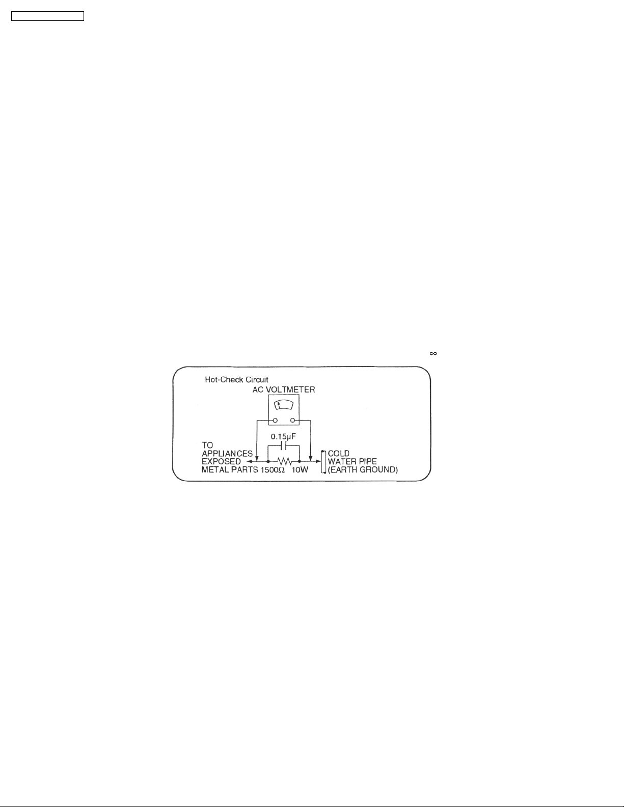
Fig. 1
1.1.2. LEAKAGE CURRENT HOT CHECK (See Figure 1.)
1. Plug the AC cord directly into the AC outlet. Do not use an isolation transformer for this check.
2. Connect a 1.5kΩ, 10 watts resistor, in parallel with a 0.15µF capacitors, between each exposed metallic part on the set and a
good earth ground such as a water pipe, as shown in Figure 1.
3. Use an AC voltmeter, with 1000 ohms/volt or more sensitivity, to measure the potential across the resistor.
4. Check each exposed metallic part, and measure the voltage at each point.
5. Reverse the AC plug in the AC outlet and repeat each of the above measurements.
6. The potential at any point should not exceed 0.75 volts RMS. A leakage current tester (Simpson Model 229 or equivalent) may
be used to make the hot checks, leakage current must not exceed 1/2 milliamp. In case a measurement is outside of the limits
specified, there is a possibility of a shock hazard, and the equipment should be repaired and rechecked before it is returned to
the customer.
4

SA-XR55P / SA-XR55PC
1.1.3. CAUTION FOR FUSE REPLACEMENT
2 Before Repair and Adjustment
Disconnect AC power, discharge Power Supply Capacitors C707, C717 and C718 through a 10Ω, 10 W resistor to ground. DO
NOT SHORT-CIRCUIT DIRECTLY (with a screwdriver blade, for instance), as this may destroy solid state devices.
After repairs are completed, restore power gradually using a variac, to avoid overcurrent.
· Current consumption at AC 120 V, 50/60 Hz in NO SIGNAL mode should be 200~800 mA.
3 Protection Circuitry
The protection circuitry may have operated if either of the following conditions are noticed:
· No sound is heard when the power is turned on.
· Sound stops during a performance.
The function of this circuitry is to prevent circuitry damage if, for example, the positive and negative speaker connection wires are
“shorted”, or if speaker systems with an impedance less than the indicated rated impedance of the amplifier are used.
If this occurs, follow the procedure outlines below:
1. Turn off the power.
2. Determine the cause of the problem and correct it.
3. Turn on the power once again after one minute.
Note :
When the protection circuitry functions, the unit will not operate unless the power is first turned off and then on again.
4 Handling the Lead-free Solder
4.1. About lead free solder (PbF)
Distinction of PbF P.C.B.:
P.C.B.s (manufactured) using lead free solder will have a PbF stamp on the P.C.B.
Caution:
· Pb free solder has a higher melting point than standard solder; Typically the melting point is 50 - 70°F (30 - 40°C) higher. Please
use a high temperature soldering iron. In case of soldering iron with temperature control, please set it to 700 ± 20°F (370 ±
10°C).
· Pb free solder will tend to splash when heated too high (about 1100°F/600°C).
· W hen soldering or unsoldering, please completely remove all of the solder on the pins or solder area, and be sure to heat the
soldering points with the Pb free solder until it melts enough.
5
SA-XR55P / SA-XR55PC
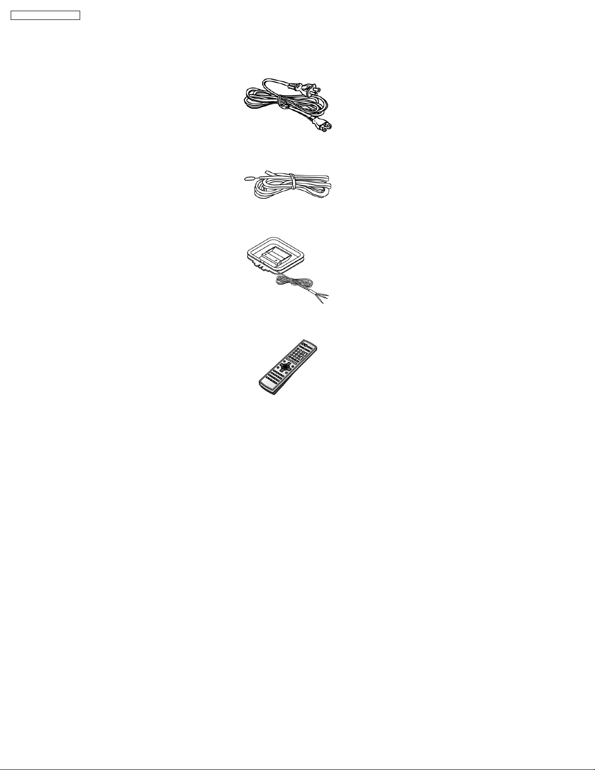
5 Accessories
Note : Refer to Packaging Materials & Accessories Part List (Section 17.3) for part number.
AC cord
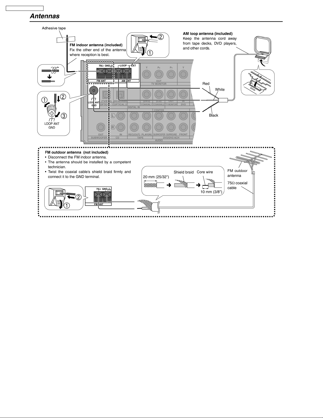
FM indoor antenna
AM loop antenna
Remote control
6
6 Operating Instructions
6.1. Main Unit
SA-XR55P / SA-XR55PC
7
SA-XR55P / SA-XR55PC
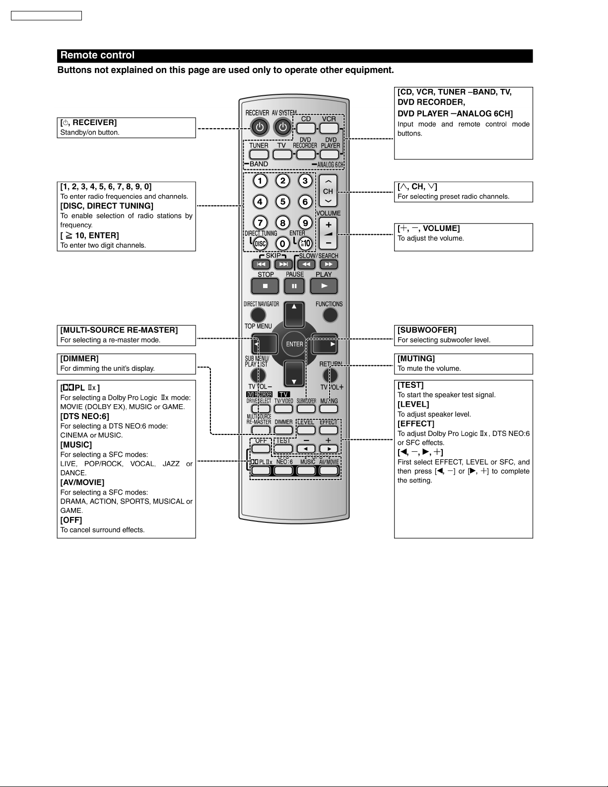
6.2. Remote Control
8
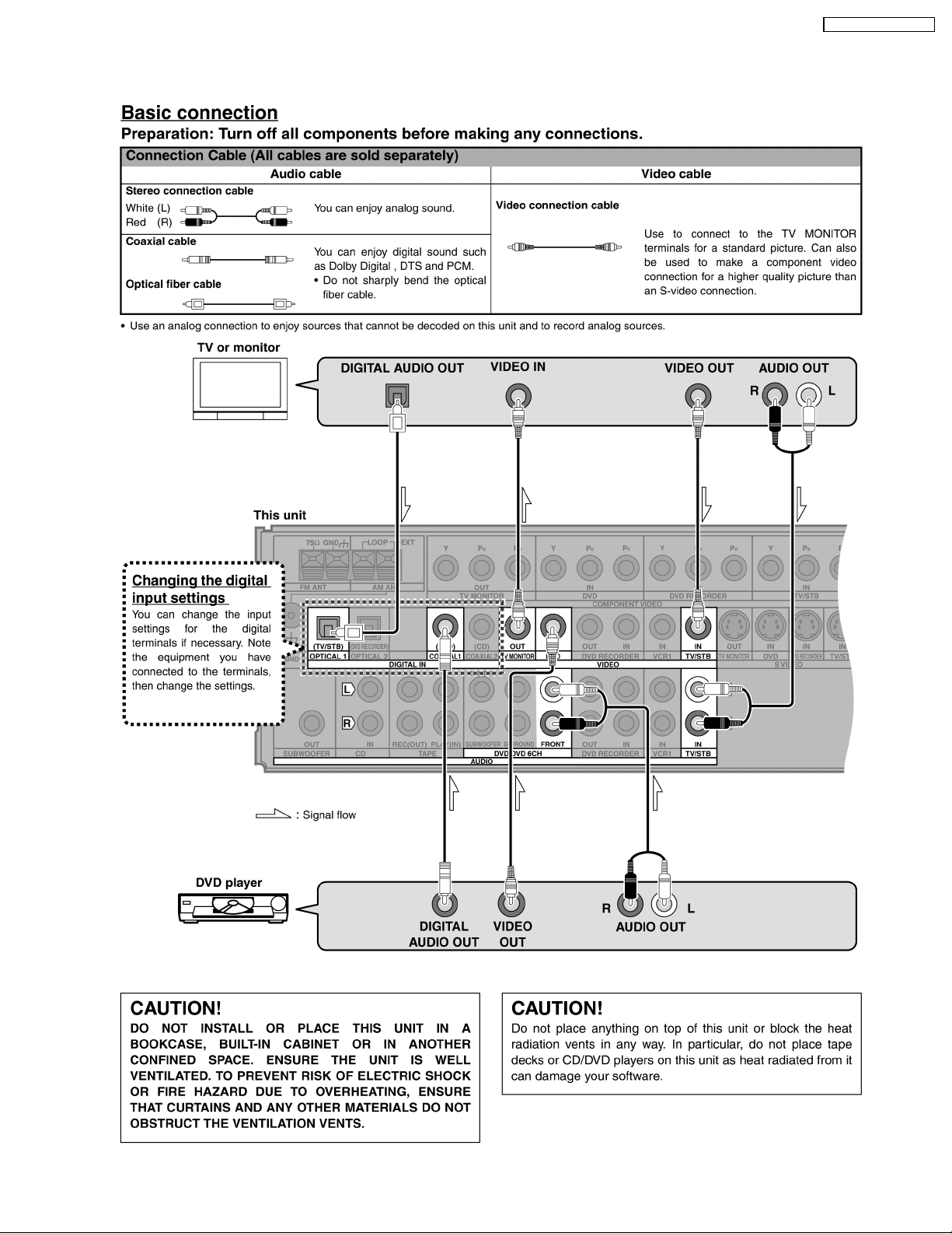
6.3. Home Theater Connections
6.3.1. TV and DVD Player
SA-XR55P / SA-XR55PC
9
SA-XR55P / SA-XR55PC
10
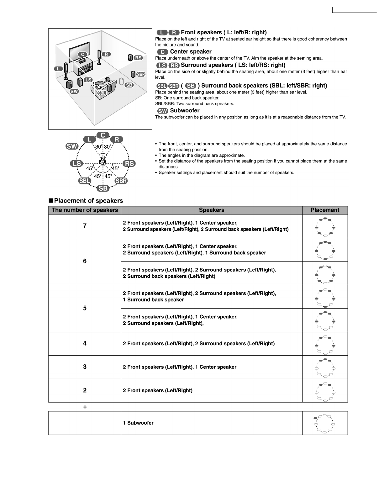
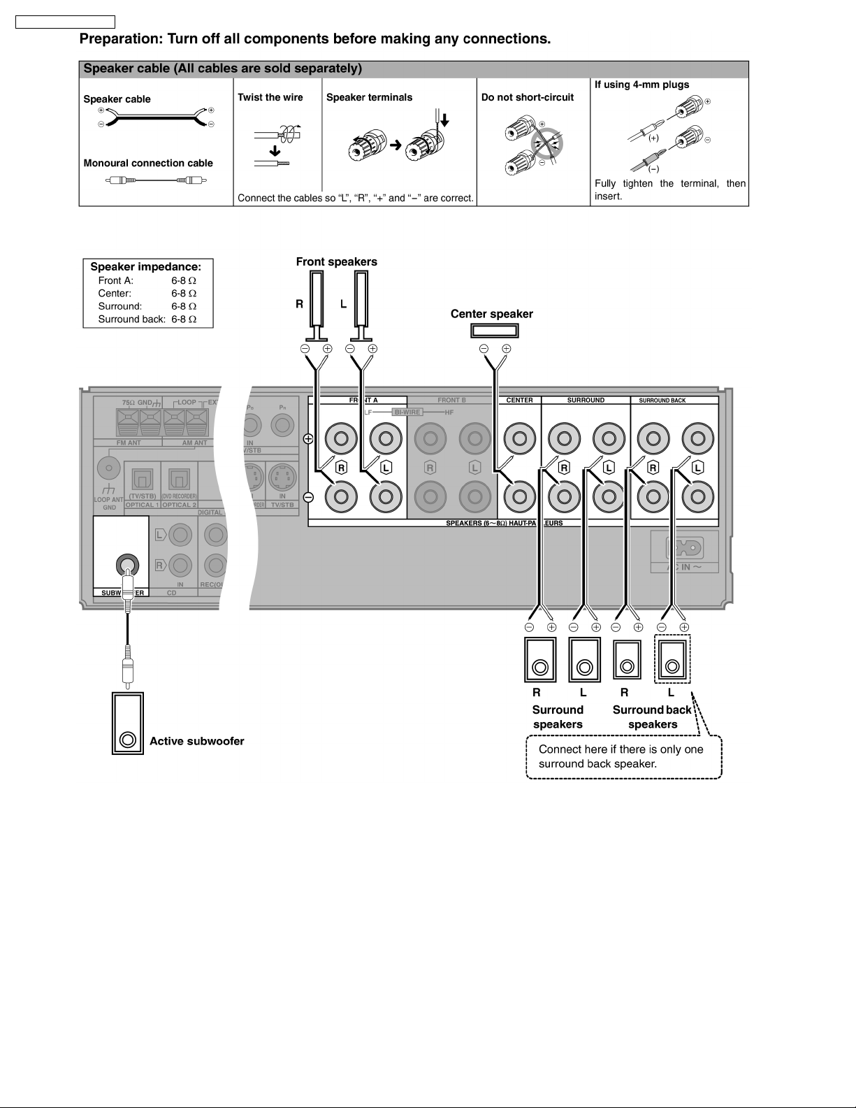
6.3.2. Speakers
SA-XR55P / SA-XR55PC
11
SA-XR55P / SA-XR55PC
12
SA-XR55P / SA-XR55PC
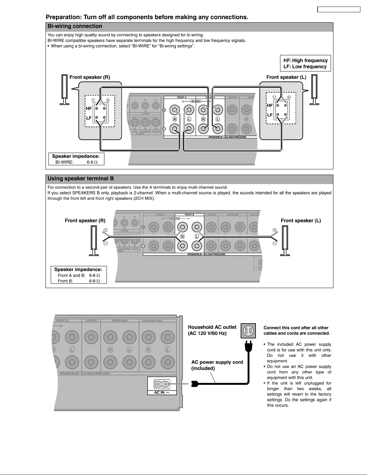
6.3.3. AC Power Supply Cord
13
SA-XR55P / SA-XR55PC
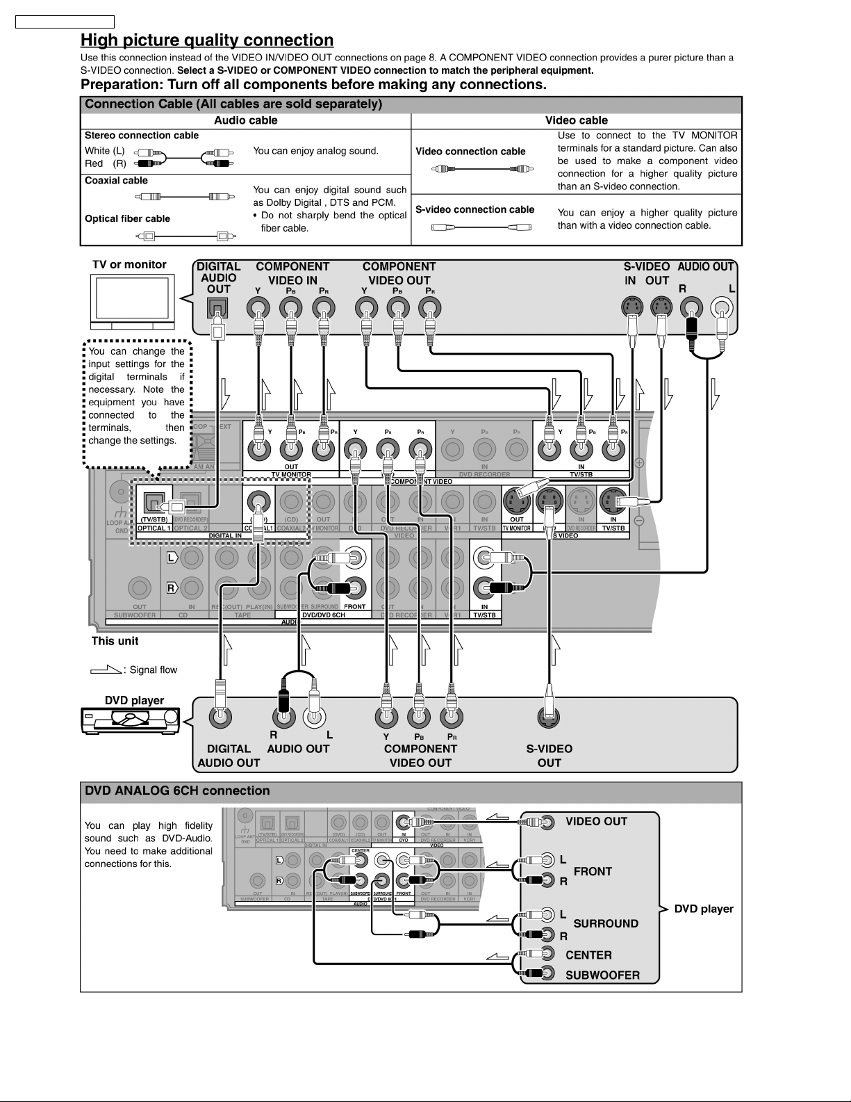
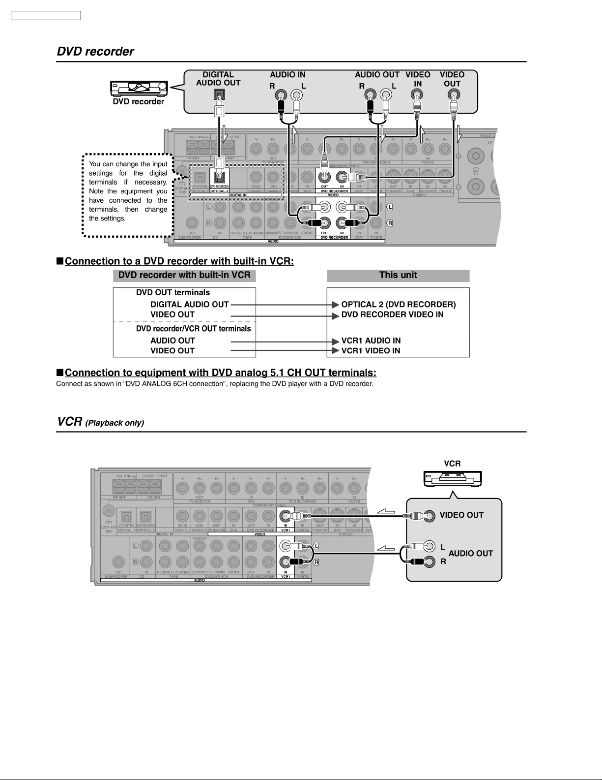
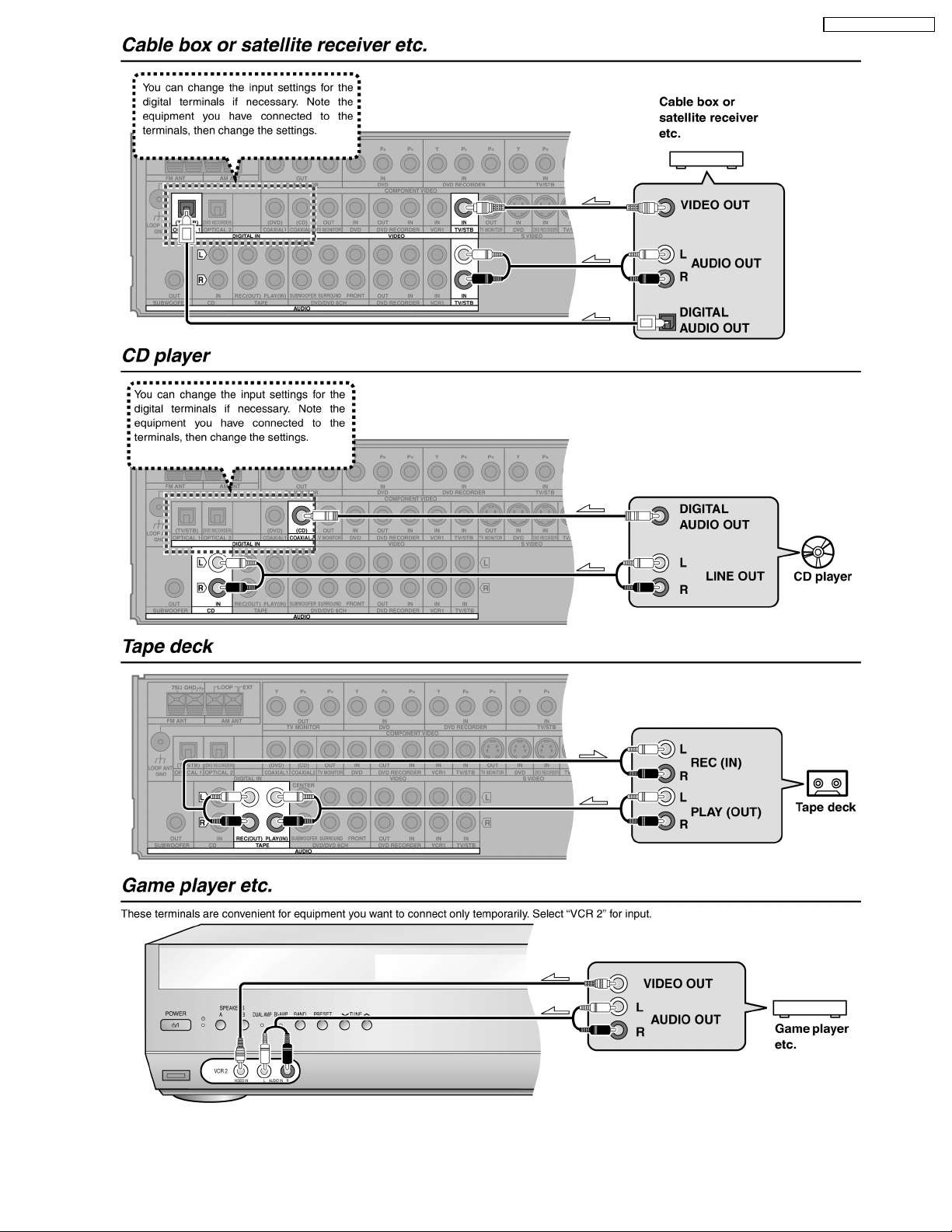
6.4. Other Connections
14
SA-XR55P / SA-XR55PC
15
SA-XR55P / SA-XR55PC
16
SA-XR55P / SA-XR55PC
7 Disassembly and Main Component Replacement
Procedures and Operational Check
“ATTENTION SERVICER”
Some chassis components may be have sharp edges. Be carefu l when disassembling and servicing.
1. This section describes procedures for checking the operation of the major printed circuit boards and replacing the main
components.
2. For reassembly after operation checks or replacement, reverse the respective procedures.
Special reassembly procedures are described only when required.
3. Select items from the following index when checks or replacement are required.
· Disassembly of Top Panel
· Checking for the DSP P.C.B. (Side A/B) and Main P.C.B. (Side A)
· Disassembly and checking of Main P.C.B. (Side B)
· Disassembly of Tuner Pack and Tuner Extent P.C.B.
· Disassembly and Checking of Speaker P.C.B.
· Disassembly and Checking of Component Video P.C.B.
· Disassembly and Checking of Video & Optical P.C.B.
· Disassembly of Rear Panel
· Disassembly of Checking of Input P.C.B.
· Disassembly of Front Panel
· Disassembly and Checking of Panel P.C.B., Volume P.C.B. and Headphone P.C.B.
· Disassembly and Checking of Power P.C.B.
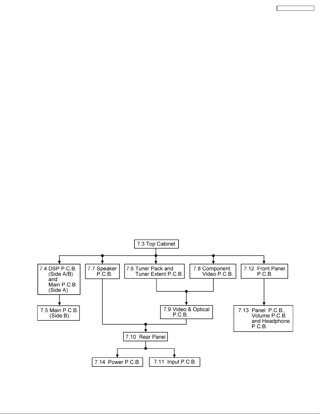
7.1. Disassembly flow chart
The following chart is the procedure for disassembling the casing and inside parts for internal inspection when carrying out the
servicing.
To assemble the unit, reverse the steps shown in the chart below.
17
SA-XR55P / SA-XR55PC
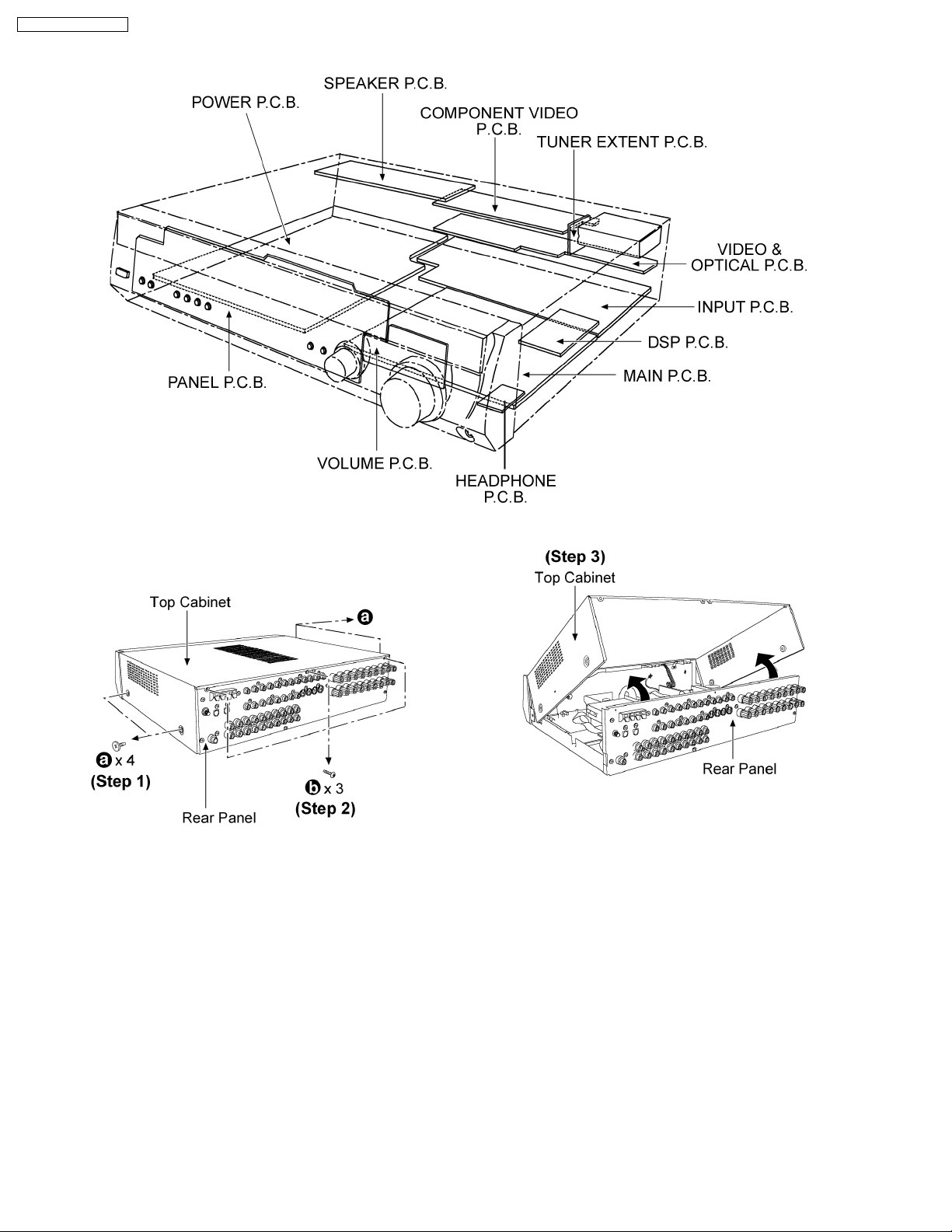
7.2. P.C.B. Positions
7.3. Disassembly of Top Cabinet.
Step 1 : Remove 4 screws from the top cabinet.
Step 2 : Remove 3 screws from the rear panel.
Step 3 : Lift up the top cabinet as arrow shown.
18
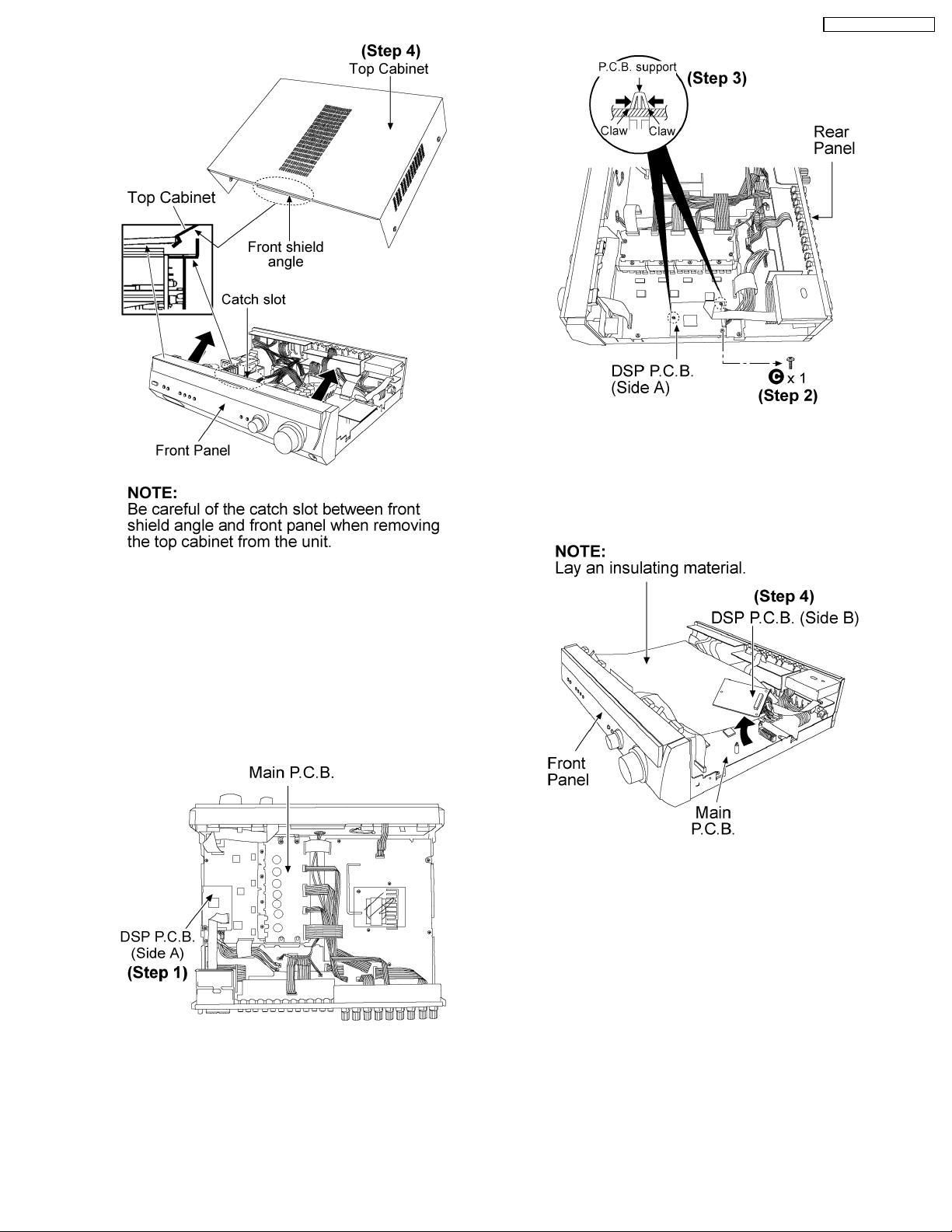
SA-XR55P / SA-XR55PC
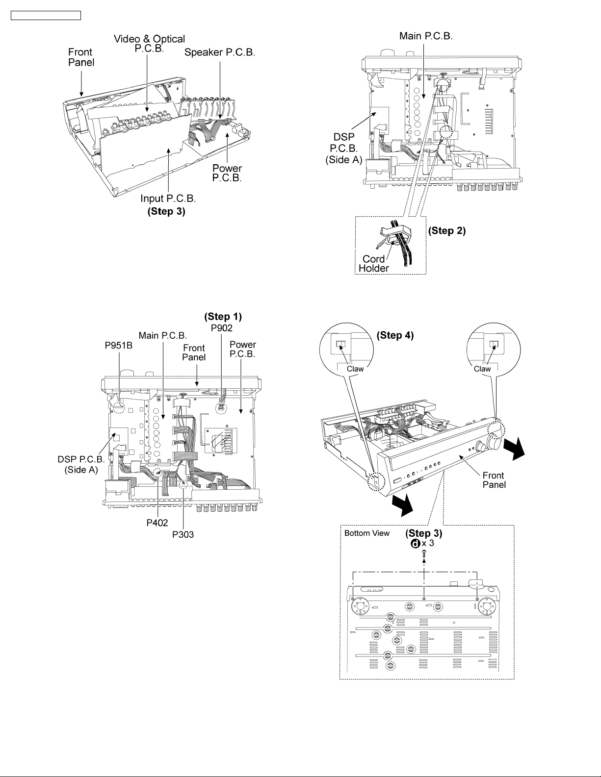
Step 2 : Remove 1 screw.
Step 3 : Release the claws of the P.C.B support then detach
the DSP. P.C.B.
Step 4 : Remove the top cabinet.
7.4. Checking for the DSP P.C.B.
(Side A/B) and Main P.C.B.
(Side A).
· Follow the (Step 1) - (Step 4) of item 7.3.
Step 4 : Flip over the DSP P.C.B. as arrow shown.
Step 1 : Check the DSP P.C.B. (Side A).
19
SA-XR55P / SA-XR55PC
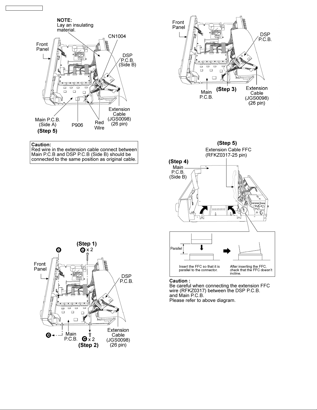
Step 3 : Detach the 25 pin FFC wire (REE1324) between
connectors P6501B (Main P.C.B.) and P6501A (Input P.C.B.)
Step 5 : Connect the DSP P.C.B. (Side B) and Main P.C.B.
(Side A) by using the extension cable then proceed with the
checking.
7.5. Disassembly and Checking of
Main P.C.B. (Side B)
· Follow the (Step 1) - (Step 4) of item 7.3.
· Follow the (Step 1) - (Step 5) of item 7.4.
Step 4 : Flip over the Main P.C.B. as arrow shown.
Step 5 : Check the Main P.C.B (Side B) by connecting the
extension cable (RFKZ0317-25 pin).
Steps 1 and 2 : Remove 4 screws altogether.
7.6. Disassembly of Tuner Pack
and Tuner Extent P.C.B.
· Follow the (Step 1) - (Step 4) of item 7.3.
20
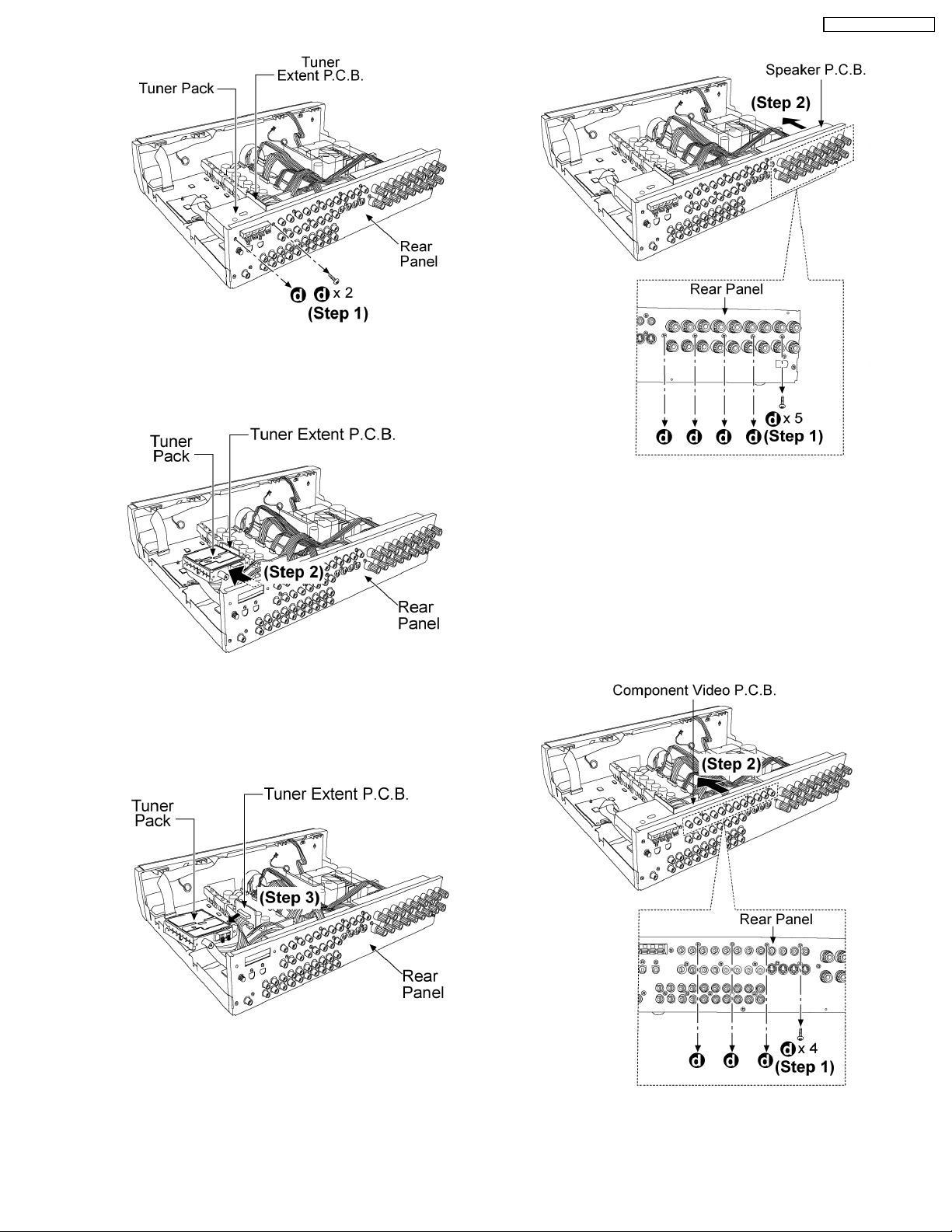
Step 1: Remove 2 screws.
SA-XR55P / SA-XR55PC
Step 2: Remove the tuner pack together with the Tuner Extent
P.C.B. from the rear panel as arrow shown.
Step 1: Remove 5 screws.
Step 2: Remove the Speaker P.C.B. from rear panel as arrow
shown for checking.
7.8. Disassembly and Checking of
Component Video P.C.B.
· Follow the (Step 1) - (Step 4) of item 7.3.
Step 3: Detach the tuner pack from the Tuner Extent P.C.B. as
arrow shown.
7.7. Disassembly and Checking of
Speaker P.C.B.
· Follow the (Step 1) - (Step 4) of item 7.3.
Step 1: Remove 4 screws.
Step 2: Remove the Component Video P.C.B. from rear panel
as arrow shown.
21
SA-XR55P / SA-XR55PC
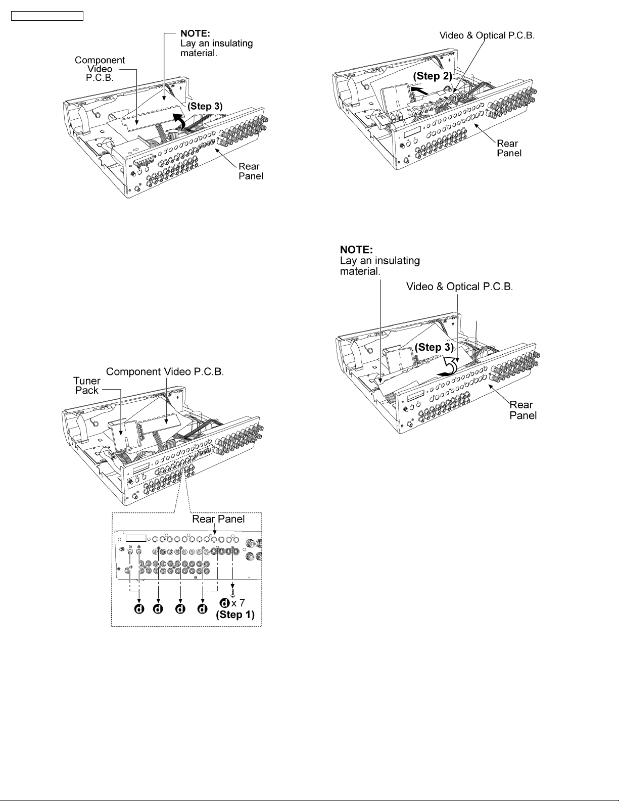
Step 3: Flip over the Component Video P.C.B. as arrow shown
for checking
7.9. Disassembly and Checking of
Video & Optical P.C.B.
· Follow the (Step 1) - (Step 4) of item 7.3.
· Follow the (Step 1) - (Step 2) of item 7.6.
· Follow the (Step 1) - (Step 3) of item 7.8.
Step 2: Remove the Video & Optical P.C.B. from rear panel as
arrow shown.
Step 1: Remove 7 screws.
Step 3: Flip over the Video & Optical P.C.B. as arrow shown for
checking
7.10. Disassembly of Rear Panel
· Follow the (Step 1) - (Step 4) of item 7.3.
· Follow the (Step 1) of item 7.6.
· Follow the (Step 1) of item 7.7.
· Follow the (Step 1) of item 7.8.
· Follow the (Step 1) of item 7.9.
22
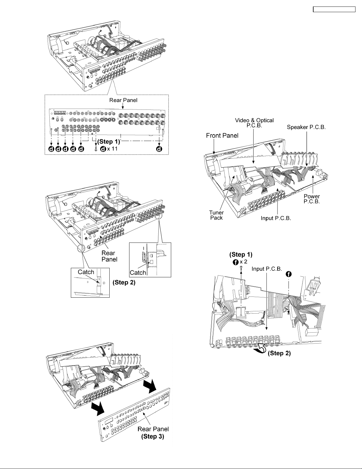
Step 1: Remove 11 screws.
SA-XR55P / SA-XR55PC
Step 3: Remove the rear panel as arrows shown.
7.11. Disassembly and Checking of
Input P.C.B.
· Follow the (Step 1) - (Step 4) of item 7.3.
· Follow the (Step 1) of item 7.6.
· Follow the (Step 1) of item 7.7.
· Follow the (Step 1) of item 7.8.
· Follow the (Step 1) of item 7.9.
· Follow the (Step 1) - (Step 3) of item 7.10.
Step 2: Be careful of the both side catches when remove the
rear panel.
Step 1: Remove 2 screws.
Step 2: Flip over the Input P.C.B. as arrow shown .
23
SA-XR55P / SA-XR55PC
Step 3: Proceed to check the Input P.C.B.
7.12. Disassembly of Front Panel
· Follow the (Step 1) - (Step 4) of item 7.3.
Step 2: Be careful when remove the wires from the cord holder.
Step 1: Disconnect all the connectors (P951B, P902, P402,
P303).
Step 3: Remove 3 screws.
Step 4: Release the both claws and remove the front panel as
arrows shown.
24
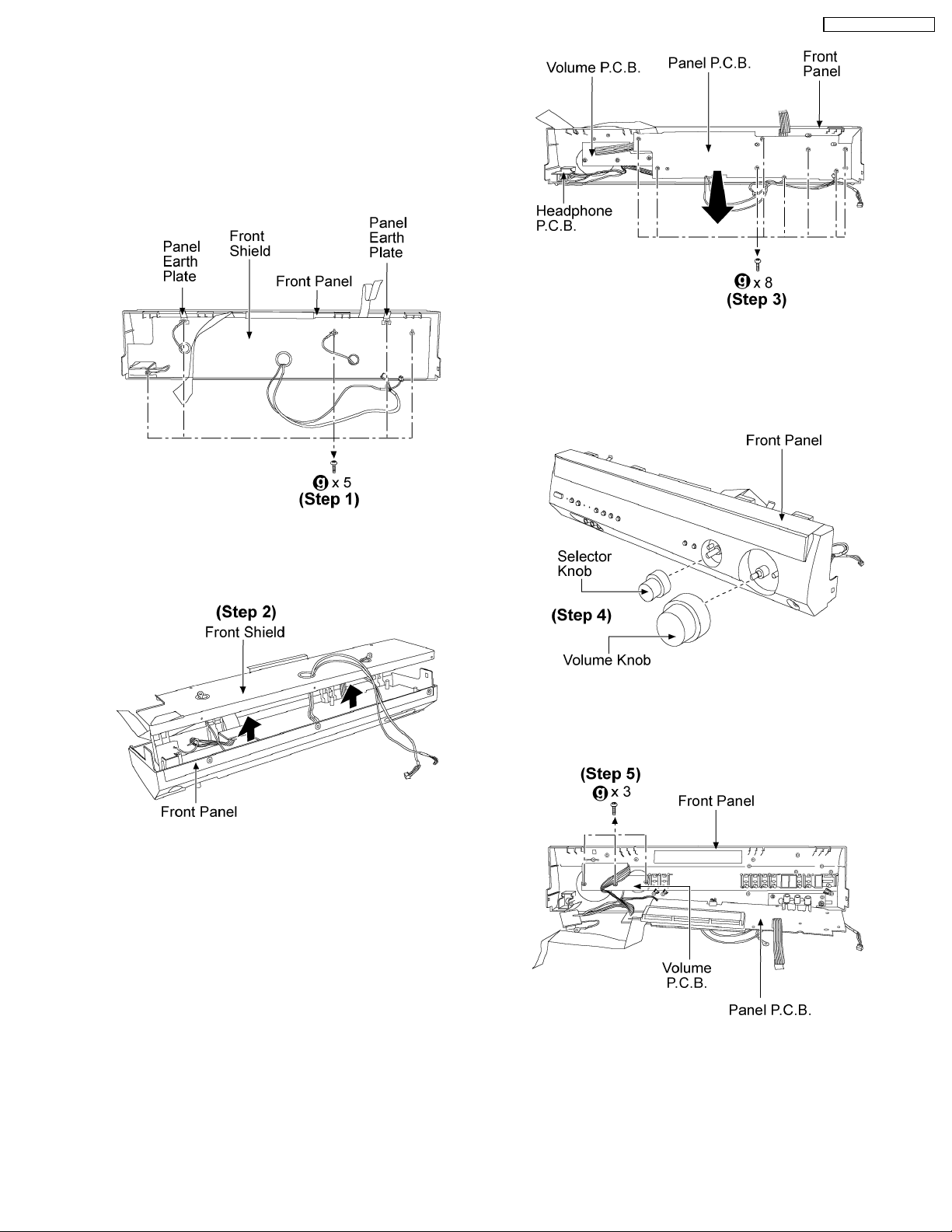
7.13. Disassembly and Checking of
Panel P.C.B., Volume P.C.B.
and Headphone P.C.B.
· Follow the (Step 1) - (Step 4) of item 7.3.
· Follow the (Step 1) - (Step 4) of item 7.12.
SA-XR55P / SA-XR55PC
Step 3: Remove 8 screws then remove the Panel P.C.B. as
arrow shown.
Step 1: Remove 5 screws.
Step 2: Remove the front shield from the front panel as arrows
shown
Step 4: Remove the Selector and Volume knobs.
Step 5: Remove 3 screws then remove the Volume P.C.B.
25
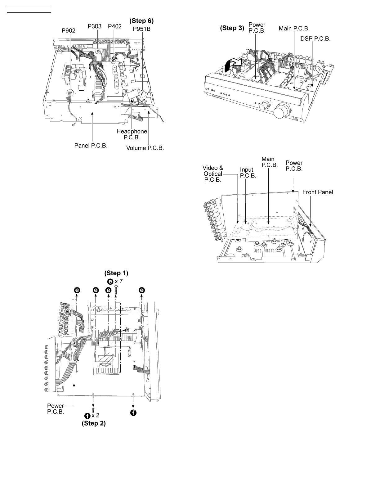
SA-XR55P / SA-XR55PC
Step 6: Reconnect all the connectors and checking for Volume
P.C.B., Panel P.C.B. and Headphone P.C.B.
7.14. Disassembly and Checking of
Power P.C.B.
Step 3: Flip over the Power Supply P.C.B. as arrow shown.
· Follow the (Step 1) - (Step 4) of item 7.3.
· Follow the (Step 1) of item 7.6.
· Follow the (Step 1) of item 7.7.
· Follow the (Step 1) of item 7.8.
· Follow the (Step 1) of item 7.9.
· Follow the (Step 1) - (Step 3) of item 7.10.
Step 4: Checking for Power P.C.B.
Steps 1 and 2: Remove 9 screws altogether.
26
SA-XR55P / SA-XR55PC
8 Self Diagnosis Display Function
This unit is equipped with the self diagnosis display function, which alarms faulty operation with error code. Use this function during
servicing.
8.1. Automatically Displayed Error Codes
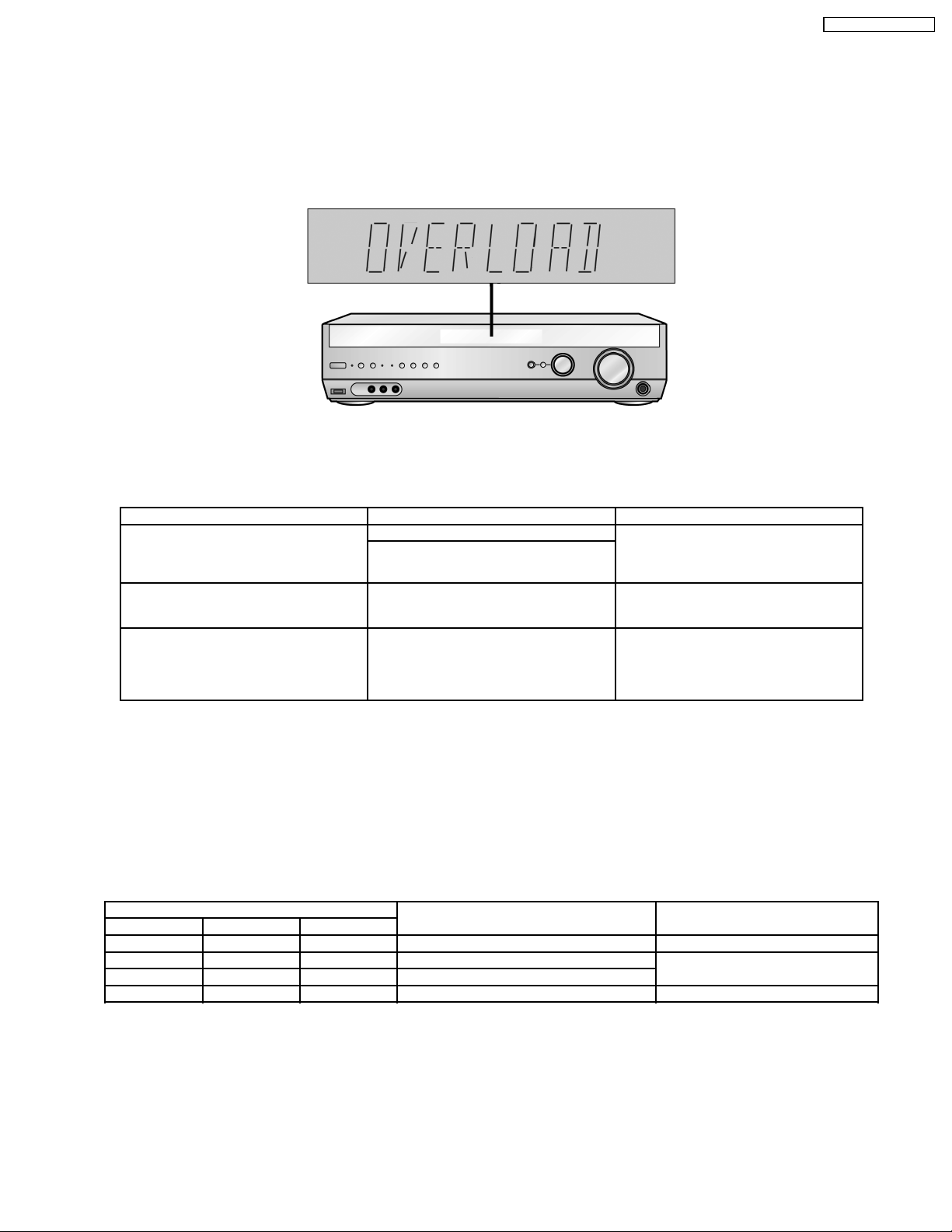
An error code automatically appears on the display (LCD) when faulty operation is detected. Refer to Fig. 8.1.
Fig. 8.1
8.2. Display Details
Refer to the following table.
LCD display Symptom Cause and Remedy
OVERLOAD Speaker short, amplifier failure Speaker short and failure in power
Humidity protection activated
F70 Communication error between sub micro-
processor and its peripheral LSI
F76 When the power is turned on, the unit
power automatically turns off; the power
cannot be turned on.
amplifier, pre-amplifier circuits. Check for
faulty parts and replace with new parts if
necessary.
Failure sub-micro processor and its
peripherals LSI. Check for faulty parts and
replace with new parts if necessary.
Failure in the power circuit system of the
unit. This may happen when the direct
current electricity is supplied to speaker
terminals. Check for the above and replace
with new parts if necessary.
8.3. Returning to Normal Display
Press the POWER button on the unit to exit the function. The power is turned off.
8.4. Overload/Shutdown Detection intenal Condition
It detects OVERLOAD, POWER MALFUNCTION with [THRM_DET], [SHORT_DET] and [DC_DET] input port. It detects the
following condition depending on the input of the port as below table.
(H: DC ± 5V / L: DC ± 0V)
PROT Detection of malfunction Display and operation
SHORT_DET THRM_DET DC_DET
H L H Normal -----
L L H Speaker Short, Malfunction of Amplifier [OVERLOAD] / POWER OFF
L H H Detection of THERMAL PROTECTION
- - L Detection of POWER MALFUNCTION [ _ _ _ F76 _ _ _ ] / POWER OFF
8.5. Overload/Thermal Detection Display
When overload is detected, automatic POWER OFF will occur. But if any key on the remote control other than the [POWER] key
is pressed before that (including the [HELP] key), the scroll display will show [SWITCH_OFF_POWER]. Then, 1 second after
display of message, [OVERLOAD] will be shown on the scroll display.
8.6. Activating Self Diagnosis Function (Servicing Mode)
This mode can be used during servicing.
27
SA-XR55P / SA-XR55PC
1. Plug the AC adapter to the power source. Press and hold down the [MULTI CONTROL] button and the [SPEAKERS A] button,
and then press the [POWER] button at the same time.
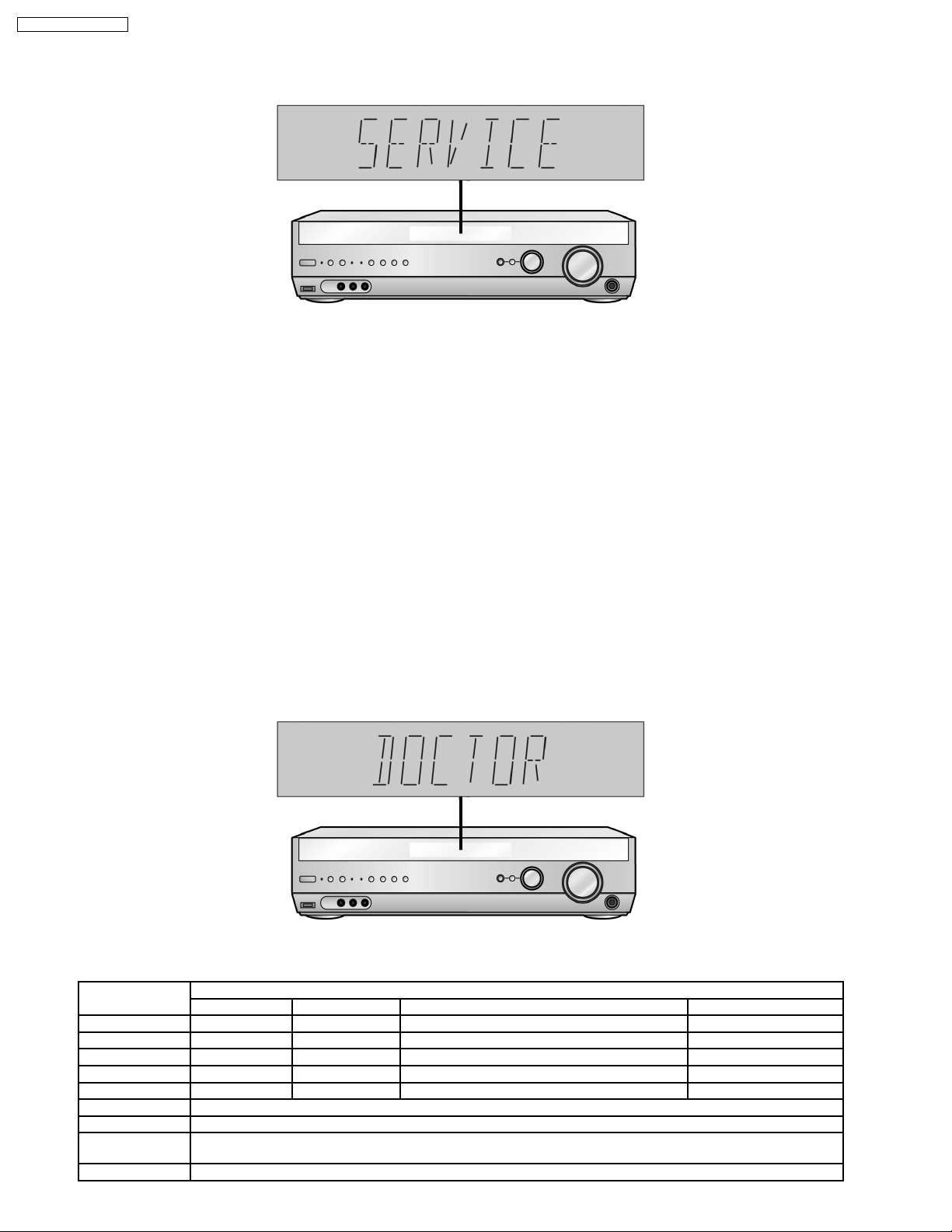
2. The message, [SERVICE] appears on the display for three seconds, and then disappears. Refer to Fig. 8.2.
Fig. 8.2
3. When the [TUNING DOWN] button is pressed, the current program filing number (ex. "M45_ ***" for MA123_45) appears. The
*** digit indicates the ROM checksum used for ROM collection, and if the unit is not loaded with ROM, "NO" appears.
When the TUNING UP button is pressed, the sub micro computer program filing number (ex. 523_***" for MA678_90) appears.
The *** digit indicates the ROM checksum used for ROM collection, and if the unit is not loaded with ROM, "NO" appears.
8.7. Analog 6.1 CH Output Check Method
When the [SUBWOOFER] button on the remote controller, the function is switched to "Input Inspection Mode", which output analog
input signals at L channe l of VCR analog input to all channels.
8.8. Returning to Normal Display
Press the POWER button on the unit to exit the function. The power is turned off.
8.9. Activating Self Diagnosis Function (Doctor Mode)
This mode can be used during servicing.
1. Plug the AC adapter to the power source. Press and hold down the MULTI-SOURCE RE-MASTER button and the SPEAKERS
A button, and then press the POWER button at the same time.
2. Initialize all the setting and set the frequency “99.7MHz” to Tuner.
The message, “_DOCTOR_” appears on the display for three seconds, and then disappears. Refer to Fig. 8.3.
Fig. 8.3
3. Doctor mode function at some remote control codes as below table.
Remote Control Test Mode Function and settings
Selector Sound Mode other settings Vol/Tone
CH 1 TUNER STEREO Frequency : FM min -48dB/0dB
CH 2 TUNER STEREO Frequency : FM max -48dB/0dB
CH 3 TUNER STEREO FM 98.3MHz -18dB/0dB
CH 4 TUNER STEREO Frequency : AM min -48dB/0dB
CH 5 TUNER STEREO Frequency : AM max -48dB/0dB
CH 8 If the input selector is TUNER, auto tuning function is started to upward on current frequency.
CH 9 If the input selector is TUNER, auto tuning function is started to downward on current frequency.
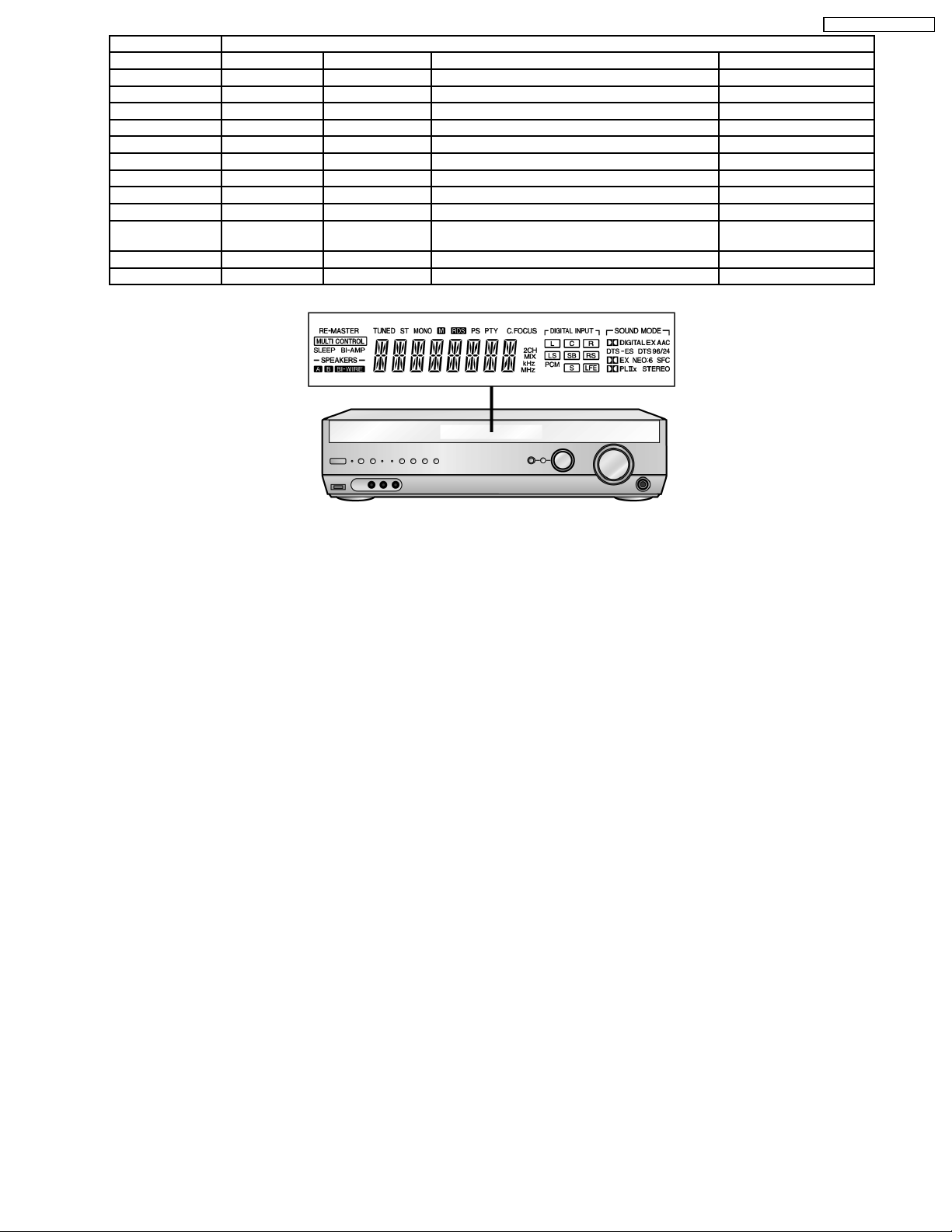
CH 0 All indicators of FL are displayed. All LED are off. Refer to Fig. 8.4.
CH UP Check Main µP software version.
Note : After this setting, only ‘POWER’ button or ‘Checker Command’ code by the remote control can be entered.
28
CH DOWN Check Sub µP software version.
SUBWOOFER VCR 1 (Analog) - All CH Output Mode -18dB/0dB
MUTING DVD 6CH - - -18dB/0dB
PLIIx CD STEREO Analog -18dB/0dB
NEO:6 TV STEREO Analog -18dB/0dB
RE-MASTER DVD STEREO Analog -18dB/0dB
LEVEL DVR/DVD_REC STEREO Analog -18dB/0dB
EFFECT CD STEREO Digital (COAX 2) -48dB/0dB
OFF TV STEREO Digital (OPT 1) -48dB/0dB
SFC AV/MOVIE DVD STEREO Digital (COAX 1) -48dB/0dB
SFC MUSIC DVR/DVD_REC STEREO Digital (OPT 2) -48dB/0dB
TEST No change SURROUND Scan the test noise output channel with 500ms
-18dB/0dB
intervals
-/L CD STEREO Balance is set to leftmost -18dB/0dB
+/R CD STEREO Balance is set to rightmost -18dB/0dB
SA-XR55P / SA-XR55PC
Fig. 8.4
29
SA-XR55P / SA-XR55PC
9 Voltage Measurement and Waveform Chart
Note:
· Indicated voltage values are the standard values for the unit measured by the DC electronic circuit tester (high-impedance)
with the chassis taken as standard.
Therefore, there may exist some errors in the voltage values, depending on the internal impedance of the DC circuit tester.
· Circuit voltage and waveform described herein shall be regarded as reference information when probing defect point
because it may differ from actual measuring value due to difference of Measuring instrument and its measuring condition
and product itself.
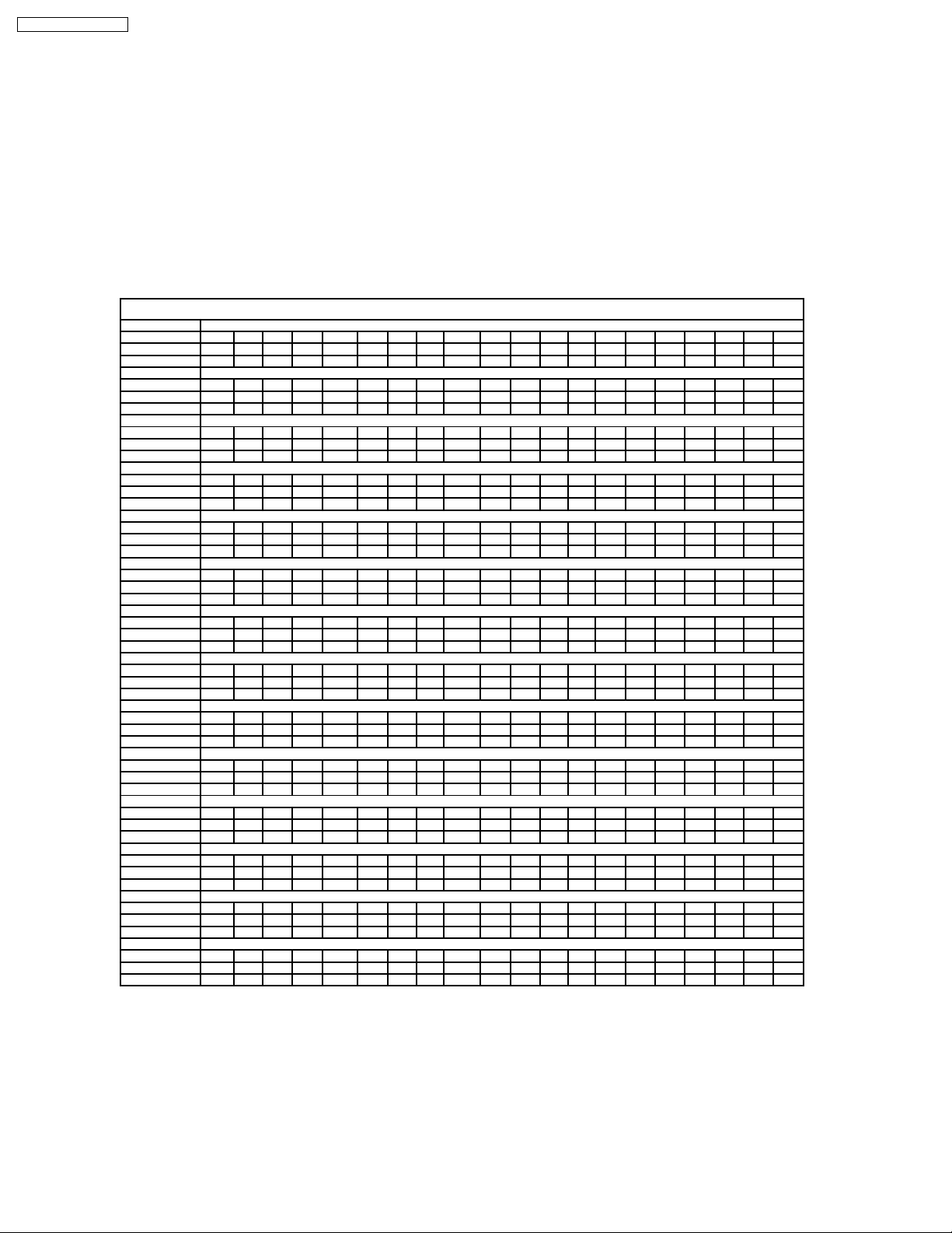
9.1. Voltage Measurement
9.1.1. DSP P.C.B.
DSP P.C.B.
Ref No.
MODE 1 2 3 4 5 6 7 8
CD PLAY 0 2.5 2.5 0 2.5 2.6 5.1 5.1
STANDBY 1.2 0.4 0.4 0 0.4 0.4 0.9 0.9
Ref No.
MODE 1 2 3 4 5
CD PLAY 0 0.1 0 0.2 0.2
STANDBY 0 0.2 0 0.1 0.1
Ref No.
MODE 1 2 3 4 5 6 7 8 9 10 11 12 13 14 15 16 17 18 19 20
CD PLAY 1.3 1.3 1.3 1.3 2.3 3.3 1.3 3.3 0 - 1.3 1.3 1.3 1.3 1.3 1.3 1.3 1.3 1.3 1.3
STANDBY 0 0 0 0 0 0 0 0 0 0 0 0 0 0000000
Ref No.
MODE 21 22 23 24 25 26 27 28 29 30 31 32
CD PLAY 0 0 0 0 0 0 0 0 0 0.8 1.3 0
STANDBY 0.1 0.1 0.1 0.1 0.1 0.1 0.1 0.1 0.1 0 0 0
Ref No.
MODE 1 2 3 4 5 6 7 8
CD PLAY 0.2 2.5 1.6 0 1.7 5.0 0 3.3
STANDBY 0.1 0.4 0 0 0 0 0 0
Ref No.
MODE 1 2 3 4 5 6 7 8
CD PLAY 2.5 1.6 1.6 0 1.6 3.3 3.3 3.3
STANDBY 0.4 0 0 0 0 0 0 0
Ref No.
MODE 1 2 3 4 5 6 7 8 9 10 11 12 13 14 15 16 17 18 19 20
CD PLAY 0 0 0 1.2 1.2 1.2 0 0 0 3.3 0 0 0 0 1.2 0 0 1.6 1.6 0
STANDBY 0 0 0 0 0 0 0 0 0 0 0 0 0 0000000
Ref No.
MODE 21 22 23 24 25 26 27 28 29 30 31 32 33 34 35 36 37 38 39 40
CD PLAY 0 1.2 1.2 0 0 0 1.2 1.2 1.2 1.6 1.6 1.6 3.3 1.7 0 1.2 1.6 1.7 1.2 0
STANDBY 0 0 0 0 0 0 0.1 0.1 0.1 0.1 0.1 0.1 0 1.4 0 0 1.4 1.4 0 0
Ref No.
MODE 41 42 43 44 45 46 47 48 49 50 51 52 53 54 55 56 57 58 59 60
CD PLAY 0 0 1.2 - 3.3 0 0 0 0 1.2 1.2 0 3.3 3.3 4.3 4.3 0 0 1.2 3.3
STANDBY 0 0 0 0 0 1.2 1.1 0 0 0 0 1.4 1.4 0 1.4 1.4 1.4 0 0 0
Ref No.
MODE 61 62 63 64 65 66 67 68 69 70 71 72 73 74 75 76 77 78 79 80
CD PLAY 0 0 1.2 1.2 1.3 1.3 1.3 2.3 0 1.2 1.2 1.2 - 1.2 1.2 1.2 0 0 1.2 1.2
STANDBY 0 0 0 0 0 0 0 0 0 0 0 0 0 0000000
Ref No.
MODE 81 82 83 84 85 86 87 88 89 90 91 92 93 94 95 96 97 98 99 100
CD PLAY 1.3 1.2 1.2 1.3 3.3 0 0 1.2 1.2 0 0 1.3 0 0 1.2 0 0 0 0 3.3
STANDBY 0 0 0 0 0 0 0 0 0 0 0 0 0 0 0 0.1 0 0 0 0
Ref No.
MODE 101 102 103 104 105 106 107 108 109 110 111 112 113 114 115 116 117 118 119 120
CD PLAY 0 0 0 0 0 0 1.2 1.2 0.8 1.3 2.3 0 0 000001.21.2
STANDBY 0 0 0 0.1 0 0 0 0 0 0 0 0 0 0000000
Ref No.
MODE 121 122 123 124 125 126 127 128 129 130 131 132 133 134 135 136 137 138 139 140
CD PLAY 3.3 3.3 0 0 0 3.3 1.2 1.2 0 0 3.3 0 0 3.3 3.3 3.3 1.2 1.2 0 0
STANDBY 0 0 0 0.1 0.1 0 0 0 0 0 0.1 0 0 0000000
Ref No.
MODE 141 142 143 144
CD PLAY 0 3.3 3.3 3.3
STANDBY 0 0 0 0
IC1001
IC1002
IC1003
IC1003
IC1005
IC1006
IC1007
IC1007
IC1007
IC1007
IC1007
IC1007
IC1007
IC1007
30
 Loading...