

Panasonic SAVK-950-EE Service manual
A
A
A
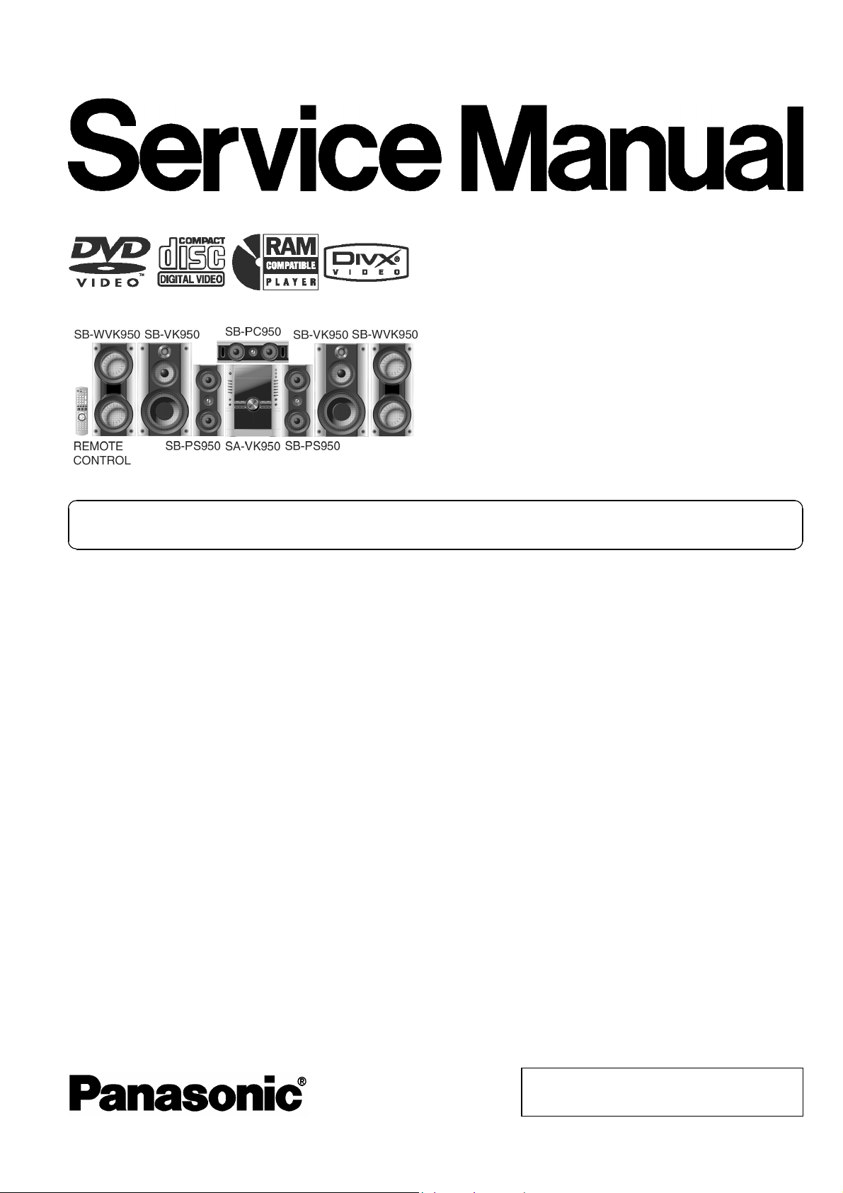
DVD Stereo System
SA-VK950EE
Colour
(S)... Silver Type
ORDER NO. MD0607237CE
Notes: This model’s DVD mechanism changer unit is CRS1D. Please refer to the original Service Manual
(Order No. MD0603065A3) for this mechanism.
Specifications
n AMPLIFIER SECTION
RMS Output Power: Dolby Digital Mode
Front - High Ch 110 W per channel (3 Ω ), 1 kHz,
10% THD
Front - Low Ch 55 W per channel (6 Ω ), 100 Hz,
10% THD
Surround Ch 110 W per channel (3 Ω ), 1 kHz,
10% THD
Center Ch 110 W per channel (3 Ω ), 1 kHz,
10% THD
Subwoofer Ch 110 W per channel (3 Ω), 100 Hz,
10% THD
Total RMS Dolby Digital mode
power
PMPO output power 10000 W
n FM/AM TUNER, TERMINALS SECTION
Preset stations FM 15 stations
Frequency Modulation (FM)
Frequency range 87.50 MHz to 108.00 MHz (50-kHz
Sensitivity 4.0 µV (IHF)
S/N 26 dB 2.2 µV
ntenna terminals 75 Ω (unbalanced)
880 W
AM 15 stations
step)
mplitude Modulation (AM)
Frequency range 522 kHz to 1629 kHz (9-kHz step)
M sensitivity S/N 20 dB at 999 kHz
1000 µV/m
Phone jack
Terminal Stereo, 3.5-mm jack
Mic jack
Sensitivity 0.7 mV, 600 Ω
Terminal Mono, 6.3-mm jack (2 system)
Music Port jack (Front)
Sensitivity 100-mV, 4.7 kΩ
Terminal Stereo, 3.5-mm jack
n CASSETTE DECK SECTION
Type Auto Reverse
Track system 4-Track, 2 Channel
Head Record/Playback Solid permalloy head
Erasure Double Gap Ferrite Head
Motor DC Servo Motor
Recording system AC Bias 100 kHz
Erase System AC Erase 100 kHz
Tape Speed 4.8 cm/s
Overall Frequency Response (+3, -6 dB) at DECK OUT
Normal 35 Hz to 14 kHz
© 2006 Matsushita Electric Industrial Co. Ltd.. All
rights reserved. Unauthorized copying and
distribution is a violation of law.
A
A
SA-VK950EE
S/N Ratio 50 dB (A weighted)
Wow and Flutter 0.18% (WRMS)
Fast Forward and Rewind Time Approx. 120 seconds with
C-60 cassette tape
n DISC SECTION
Disc played [8 cm or 12 cm]
(1) DVD (DVD-Video, DivX )
(2) DVD-RAM (DVD-VR, JPEG , MP3 , MPEG4 , DivX )
(3) DVD-R (DVD-Video, DVD-VR, JPEG , MP3 , MPEG4 ,
# 1,#2
DivX
)
#1,#2
#2,#3
#2,#4
#2,#3
#2,#4
#2,#5
#1,#2
#2,#5
(4) DVD-R DL (DVD-Video, DVD-VR)
(5) DVD-RW (DVD-Video, DVD-VR, JPEG , MP3 , MPEG4
2,#5
, DivX
# 1,#2
)
#2,#3
#2,#4
#
(6) +R/ +RW (Video)
(7) +R DL (Video)
#6
(8) CD,CD-R/RW [CD-DA, Video CD, SVCD , MP3 , WMA ,
JPEG
# 2,#3
, MPEG4
# 2,#5
, DivX
# 1,#2
, HighMAT Level 2 (Audio and
#2,#4
#2,#7
Image)]
#1
Plays all versions of DivX video (including DivX 6) with standard
®
®
playback of DivX®media files. Certified to the DivX Home Theater
Profile. GMC (Global Motion Compensation) is not supported.
#2
The total combined maximum number of recognizable audio,
picture and video contents and groups: 4000 audio, picture and video
contents and 400 groups.
#3
Exif Ver 2.1 JPEG Baseline files
Picture resolution: between 160 x 120 and 6144 x 4096 pixels
(Sub sampling is 4:0:0, 4:2:0, 4:2:2 or 4:4:4). Extremely long and
narrow pictures may not be displayed.
#4
MPEG-1 Layer 3, MPEG-2 Layer 3
#5
MPEG4 data recorded with the Panasonic SD multi cameras or
DVD video recorders.
Conforming to SD VIDEO specifications (ASF standard) / MPEG4
(Simple Profile) video system / G.726 audio system
#6
Conforming to IEC62107
#7
Windows Media Audio Ver. 9.0 L3
Not compatible with Multiple Bit Rate (MBR)
Pick up
Wavelength (DVD/CD) 662 nm/785 nm
Laser power (DVD/CD) CLASS 1 / CLASS 1M
udio output (Disc)
Number of channels (FL,FR,C,SL,SR,SW),5.1ch
udio performance (measurement at: Rec out terminal)
Frequency response (CD-Audio) 4Hzto20kHz
n VIDEO SECTION
Video system
Signal system PAL625/50, PAL525/60, NTSC
Composite video output
Output level 1Vp-p(75Ω)
Terminal Pin jack (1 system)
S-video output
Y output level 1Vp-p(75Ω)
C output level 0.3 Vp-p (75 Ω )(PAL)
0.286 Vp-p (75 Ω )(NTSC)
Terminal S terminal (1 system)
Component video output
[NTSC : 480p / 480i, PAL: 576p / 576i]
Y output level 1Vp-p(75Ω)
PBoutput level 0.7 Vp-p (75 Ω )
PRoutput level 0.7 Vp-p (75 Ω )
Terminal
Pin jack (Y: green, PB:blue,PR:red)(1system)
n GENERAL
Power supply AC 230 V, 50Hz
Power consumption 360 W
Power consumption in standby mode:
0.5 W (approximate)
Dimensions (W x H x D) 250 x 330 x 334.6 mm
Mass 5.5 kg
Operating temperatur e range +5to+35°C
Operating humidity range 5% to 90% RH (no condensation)
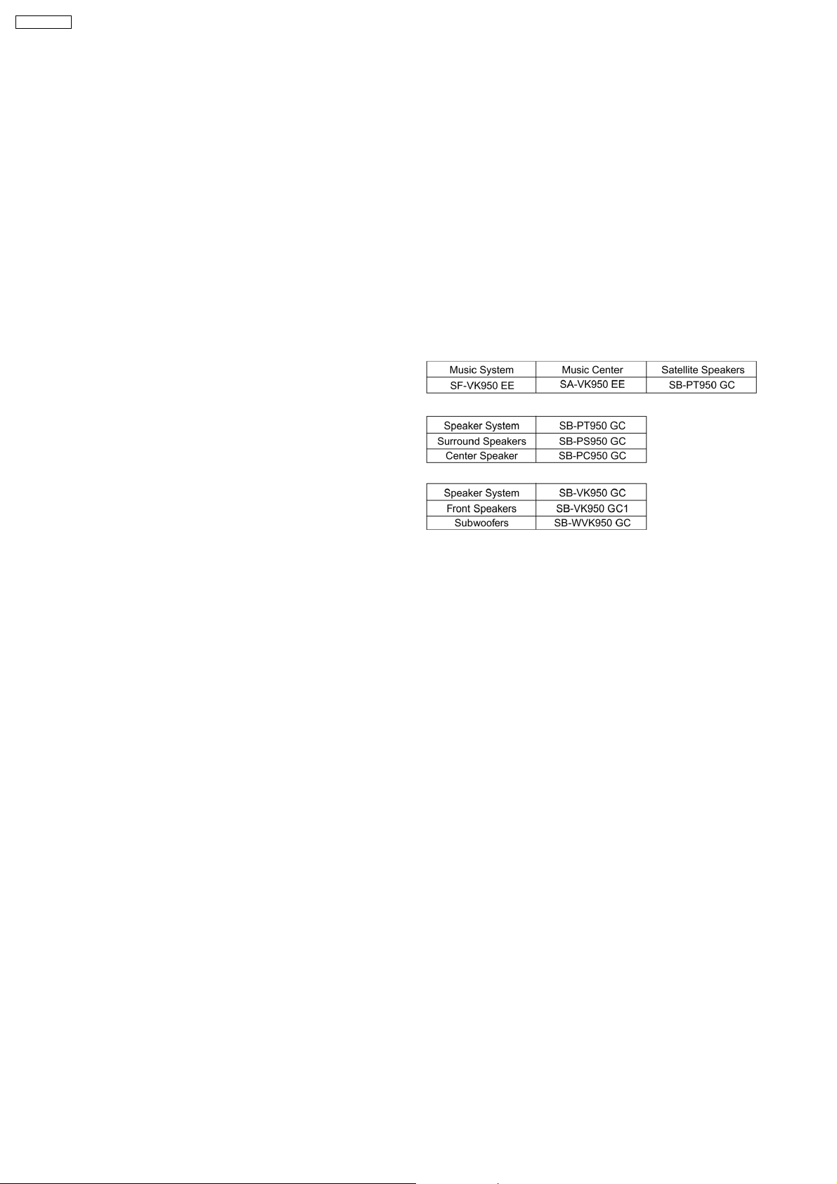
n SYSTEM
For information on speaker system, please refer to the original
Service Manual (Order No. MD0605195C3) for SB-VK950GC1-S,
(Order No. MD0605194C3) for SB-PC950GC-S, (Order No.
MD0605199C3) for SB-PS950GC-S & (Order No. MD0605200C3) for
SB-WVK950GC-S..
2
Notes:
1. Specifications are subject to change without notice.
Mass and dimensions are approximate.
2. Total harmonic distortion is measured by the digital spectrum
analyzer.
SA-VK950EE
3

SA-VK950EE
CONTENTS
Page Page
1 Safety Precautions 6
1.1. General Guidelines
1.2. Safety Precaution for AC Power Supply Cord
1.3. Before Repair and Adjustment
1.4. Protection Circuitry
2 Prevention of Electro Static Discharge (ESD) to
Electrostatically Sensitive (ES) Devices
3 Handling Precautions for Traverse Unit
3.1. Handling Optical Pickup
3.2. Replacing Precautions for Optical Pickup Unit
3.3. Grounding for Preventing Electrostatic Destruction
4 Precaution of Laser Diode
5 Warning
5.1. Service caution based on legal restrictions
6 Accessories
7 Operation Procedures
7.1. Main Unit Operation Control
7.2. Remote Control Operation Control
7.3. Disc Information
7.4. DivX VOD Content
8 New Features
8.1. CRS1D Mechanism Overview
8.2. Music Port
9 About HighMAT
9.1. What 痴 HighMAT?
9.2. Why take advantage of HighMAT?
9.3. Benefits of HighMAT?
10 Self diagnosis and special mode setting
10.1. Service Mode Summary Table
10.2. Service Mode Table 1
10.3. Special Mode Table 2
11 Assembling and Disassembling
11.1. Caution
11.2. Disassembly flow chart
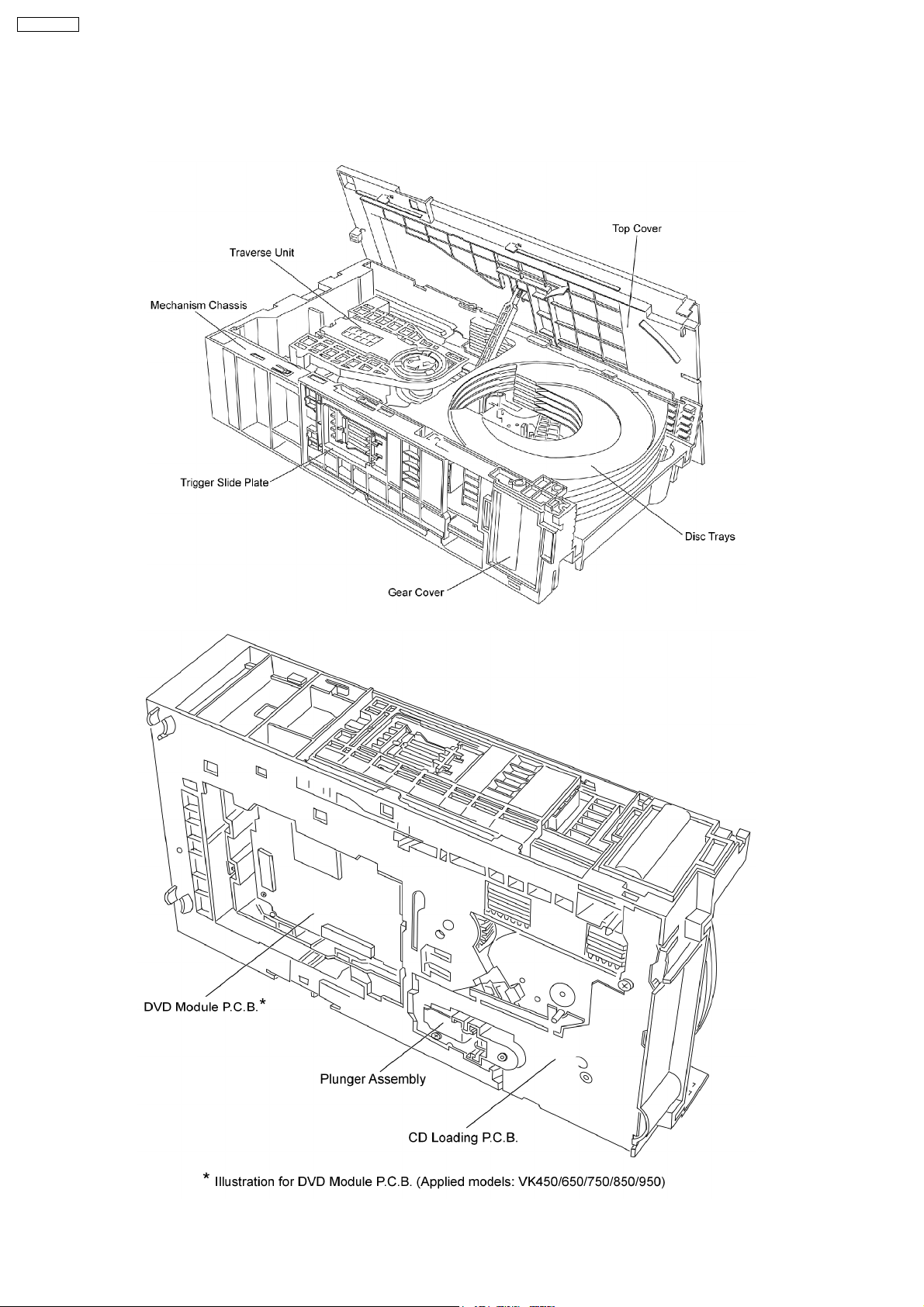
11.3. Main Parts Location
11.4. Disassembly of Top Cabinet
11.5. Disassembly of CD/DVD Changer Unit (CRS1D)
11.6. Disassembly of Rear Panel
11.7. Disassembly of Main P.C.B.
11.8. Disassembly of Front Panel Unit
11.9. Disassembly of SMPS P.C.B.
11.10. Replacement of Power Amp IC (SMPS P.C.B.)
11.11. Disassembly of Digital Amp P.C.B.
11.12. Replacement for Power Amp IC (Digital Amp P.C.B.)
10
11
11
12
13
13
14
15
17
18
18
20
21
21
21
22
25
25
25
33
41
41
42
43
44
44
45
46
46
47
47
48
48
6
7
7
7
8
9
9
9
9
11.13. Disassembly of Panel P.C.B., Mic P.C.B. & Tact Switch
P.C.B.
11.14. Disassembly of Deck mechanism unit
11.15. Disassembly of Deck P.C.B.
11.16. Disassembly of Traverse Unit
11.17. Disassembly of optical pickup unit (CD/DVD mechanism )
11.18. Disassembly of Deck Mechanism
11.19. Replacement for cassette lid
11.20. Rectification for tape jam problem
12 Service Fixture and Tools
13 Service Positions
13.1. Checking and Repairing of Main P.C.B.
13.2. Checking and Repairing of SMPS P.C.B. & Digital Amp
P.C.B.
13.3. Checking and Repairing of Panel, Deck & Deck
Mechanism P.C.B.
14 Adjustment Procedures
14.1. Cassette Deck Section
14.2. Tuner section
14.3. Alignment Points
15 Voltage and Waveform Chart
15.1. DVD Module P.C.B.
15.2. Main P.C.B.
15.3. Panel P.C.B.
15.4. Deck P.C.B. & Deck Mechanism P.C.B.
15.5. Damp P.C.B. & Mic P.C.B.
15.6. Waveform Chart
16 Wiring Connection Diagram
17 Block Diagram
18 Notes of Schematic Diagrams
19 Schematic Diagram
19.1. Optical Pickup Unit Circuit
19.2. (A) DVD Module (DV3.2) Circuit
19.3. (B) Main Circuit
19.4. (C) Panel Circuit
19.5. (D) Tact Switch Circuit & (E) Mic Circuit
19.6. (F) Damp Circuit
19.7. (G) Speaker Circuit
19.8. (H) SMPS Circuit
19.9. (I) Deck Circuit & (J) Deck Mechanism Circuit
20 Printed Circuit Board
20.1. (A) DVD Module P.C.B. (Side A & B )
20.2. (B) Main P.C.B.
20.3. (C) Panel P.C.B.
49
50
50
51
52
54
58
58
60
60
60
61
62
63
63
64
64
65
66
68
71
72
73
74
83
85
91
93
93
94
98
102
103
104
106
107
109
111
112
113
114
4

SA-VK950EE
20.4. (D) Tact Switch P.C.B., (E) Mic P.C.B., (I) Deck P.C.B. &
(J) Deck Mechanism P.C.B.
20.5. (F) Damp P.C.B. & (G) Speaker P.C.B.
20.6. (H) SMPS P.C.B.
21 Basic Troubleshooting Guide for Backend Module
21.1. Firmware and Key Download
21.2. Initialisation and Playability
22 Illustration of ICs, Transistors and Diodes
115
116
117
119
119
119
120
23 Terminal Function of IC
23.1. IC2600 (C2CBYY0 00269) System Microprocessor
24 Exploded Views
24.1. Cabinet Parts Location
24.2. Deck Mechanism Parts Location (RAA3413-1S)
24.3. Packaging
25 Replacement Parts List
121
121
123
123
125
126
129
5
SA-VK950EE
1 Safety Precautions
1.1. General Guidelines
1. When servicing, observe the original lead dress. If a short circuit is found, replace all parts which have been overheated or
damaged by the short circuit.
2. After servicing, see to it that all the protective devices such as insulation barriers, insulation papers shields are properly
installed.
3. After servicing, make the following leakage current checks to prevent the customer from being exposed to shock hazards.
1.1.1. Leakage Current Cold Check
1. Unplug the AC cord and connect a jumper between the two prongs on the plug.
2. Measure the resistance value, with an ohmmeter, between the jumpered AC plug and each exposed metallic cabinet part on
the equipment such as screwheads, connectors, control shafts, etc. When the expose d metallic part has a return path to the
chassis, the reading should be between 1MΩ and 5.2MΩ.
When the exposed metal does not have a return path to the chassis, the reading must be
.
Figure 1
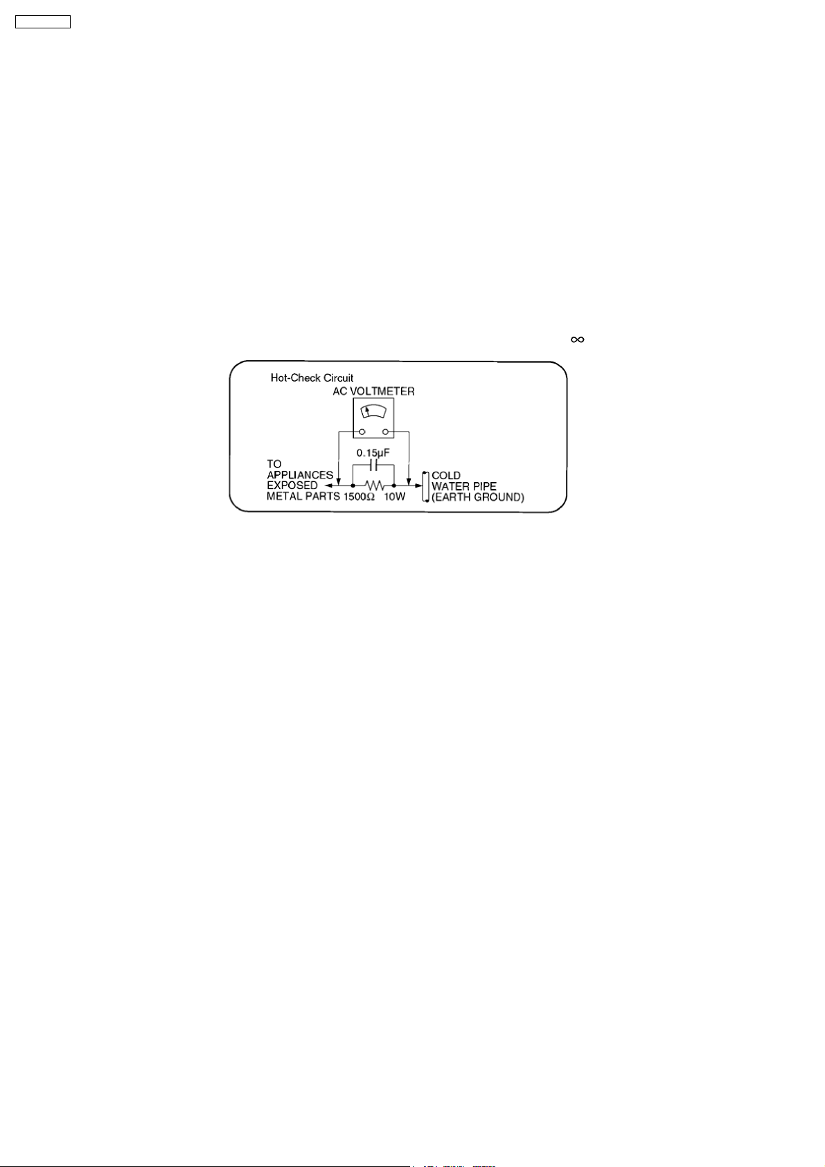
1.1.2. Leakage Current Hot Check
(See Figure 1)
1. Plug the AC cord directly into the AC outlet. Do not use an isolation transformer for this check.
2. Connect a 1.5kΩ, 10 watts resistor, in parallel with a 0.15µF capacitor, between each exposed metallic part on the set and a
good earth ground such as a water pipe, as shown in Figure 1.
3. Use an AC voltmeter, with 1000 ohms/volt or more sensitivity, to measure the potential across the resistor.
4. Check each exposed metallic part, and measure the voltage at each point.
5. Reverse the AC plug in the AC outlet and repeat each of the above measurements.
6. The potential at any point should not exceed 0.75 volts RMS. A leakage current tester (Simpson Model 229 or equivalent) may
be used to make the hot checks, leakage current must not exceed 1/2 milliamp. In case a measurement is out of the limits
specified, there is a possibility of a shock hazard, and the equipment should be repaired and rechecked before it is returned to
the customer.
6

1.2. Safety Precaution for AC Power Supply Cord
SA-VK950EE
1.3. Before Repair and Adjustment
Disconnect AC power, discharge Power Supply Capacitors C2254, C2256, C2288, C2289, C2632, C2721, C2725, C2811, C2815,
C2817, C5512, C5513 , C5514 , C5712 , C5713 , C5715, C5718 , C5790 , C5805 , C5806 , C5807 , C5914, C5916, C5917 , C5929 ,
C5930, C5971 and C5977 through a 10Ω, 5W resistor to ground.
DO NOT SHORT-CIRCUIT DIRECTLY (with a screwdriver blade, for instance), as this may destroy solid state devices.
After repairs are completed, restore power gradually using a variac, to avoid overcurrent.
Current consum ption at AC 230V, 50 Hz in NO SIGNAL (vol. min, at CD mode) should be ~500mA.
1.4. Protection Circuitry
The protection circuitry may have operated if either of the following conditions are noticed:
· No sound is heard when the power is turned on.
· Sound stops during a performance.
The function of this circuitry is to prevent circuitry damage if, for example, the positive and negative speaker connection wires are
“shorted”, or if speaker systems with an impedance less than the indicated rated impedance of the amplifier are used.
If this occurs, follow the procedure outlines below:
1. Turn off the power.
2. Determine the cause of the problem and correct it.
3. Turn on the power once again after one minute.
Note :
When the protection circuitry functions, the unit will not operate unless the power is first turned off and then on again.
7
SA-VK950EE
2 Prevention of Electro Static Discharge (ESD) to
Electrostatically Sensitive (ES) Devices
Some semiconducto r (solid state) devices can be damaged easily by electricity. Such components commonly are called
Electrostatically Sensitive (ES) Devices. Examples of typical ES devices are integrated circuits and some field-effect transistors and
semiconductor “chip” components. The following techniques should be used to help reduce the incidence of component damage
caused by electro static discharge (ESD).
1. Immediately before handling any semiconductor component or semiconductor-equipped assembly, drain off any ESD on your
body by touchin g a known earth ground. Alternatively, obtain and wear a commercially available discharging ESD wrist strap,
which should be removed for potential shock reasons prior to applying power to the unit under test.
2. After removing an electrical assembly equipped with ES devices, place the assembly on a conductive surface such as
aluminium foil, to prevent electrostatic charge build up or exposu re of the assembly.
3. Use only a grounded-tip soldering iron to solder or unsolder ES devices.
4. Use only an anti-static solder remover device. Some solder removal devices not classified as “anti-static (ESD protected)” can
generate electrical charge to damage ES devices.
5. Do not use freon-propelled chemicals. These can generate electrical charges sufficient to damage ES devices.
6. Do not remove a replacement ES device from its protective package until immediately before you are ready to install it. (Most
replacement ES devices are packaged with leads electrically shorted together by conductive foam, aluminium foil or
comparable conductive material).
7. Immediately before removing the protective material from the leads of a replacement ES device, touch the protective material
to the chassis or circuit assembly into which the device will be installed.
Caution
Be sure no power is applied to the chassis or circuit, and observe all other safety precautions.
8. Minimize body motions when handling unpackaged replacement ES devices. (Otherwise harmless motion such as the brushing
together of your clothes fabric or the lifting of your foot from a carpeted floor can generate static electricity (ESD) sufficient to
damage an ES device).
8
SA-VK950EE
3 Handling Precautions for Traverse Unit
The laser diode used inside optical pickup could be destroyed due to static electricity as a potential difference is caused by
electrostatic load discharged from clothes or human body. Handling the parts carefully to avoid electrostatic destruction during
repair.
3.1. Handling Optical Pickup
1. Do not impact on optical pickup as the unit structurally uses an extremely precise technology.
2. Short-circuit the flexible cable of optical pickup remove from the circuit board using a short-circuit pin or clip in order to prevent
laser diode from electrostatic destruction (Refer to Fig. 3.1 and Fig. 3.2)
3. Do not handle flexible cables forcibly as this may cause snapping. Handle the parts carefully (Refer to Fig. 3.1)
4. A new optical pickup is equipped with an anti-static flexible cable. After replacing and connecting to the flexible board, cut the
anti-static flexible cable. (Refer to Fig. 3.1)
Fig 3.1
3.2. Replacing Precautions for Optical Pickup Unit
CD/DVD Optical Pickup
The optical pickup by which part supply was carried out attaches the short clip to the flexible board for laser diode electrostatic
discharge damage prevention. Please remove the short clip and be sure to check that the short land is open, before connecting.
(Please remove solder, when the short land short-circuits.)
3.3. Grounding for Preventing Electrostatic Destruction
1. Human body grounding
Use the anti-static wrist strap to discharge the static electricity accumulated in your body. (Refer to Fig. 3.2)
2. Work place grounding
Place a conductive material (conductive sheet) or ironboard where optical pickup is placed. (Refer to Fig. 3.2)
Note :
Keep your clothes away from optical pickup as wrist strap does not release the static electricity charged in clothes.
Fig. 3.2
9
SA-VK950EE
4 Precaution of Laser Diode
Caution :
This product utilizes a laser diode with the unit turned "ON", invisible laser radiation is emitted from the pick up lens.
Wavelength : 785 nm(CD)/662 nm(DVD)
Maximum output radiation power from pick up : 100 µW/VDE
Laser radiation from pick up unit is safety level, but be sure the followings:
1. Do not disassemble the optical pick up unit, since radiation from exposed laser diode is dangerous.
2. Do not adjust the variable resistor on the pick up unit. It was already adjusted.
3. Do not look at the focus lens using optical instruments.
4. Recommend not to look at pick up lens for a long time.
CAUTION!
THIS PRODUCT UTILIZES A LASER.
USE OF CONTROLS OR ADJUSTMENTS OR PERFORMANCE OF PROCEDURES OTHER THAN THOSE SPECIFIED HEREIN MAY RESULT
IN HAZARDOUS RADIATION EXPOSURE.
n Use of Caution Labels
10

SA-VK950EE
5 Warning
5.1. Service caution based on legal restrictions
5.1.1. General description about Lead Free Solder (PbF)
The lead free solder has been used in the mounting process of all electrical components on the printed circuit boards used for this
equipment in considering the globally environmental conservation.
The normal solder is the alloy of tin (Sn) and lead (Pb). On the other hand, the lead free solder is the alloy mainly consists of tin
(Sn), silver (Ag) and Copper (Cu), and the melting point of the lead free solder is higher approx.30 degrees C (86°F) more than that
of the normal solder.
Definition of PCB Lead Free Solder being used
The letter of “PbF” is printed either foil side or components side on the PCB using the lead free solder.
(See right figure)
Service caution for repair work using Lead Free Solder (PbF)
· The lead free solder has to be used when repairing the equipment for which the lead free solder is used.
(Definition: The letter of “PbF” is printed on the PCB using the lead free solder.)
· To put lead free solder, it should be well molten and mixed with the original lead free solder.
· Remove the remaining lead free solder on the PCB cleanly for soldering of the new IC.
· Since the melting point of the lead free solder is higher than that of the normal lead solder, it takes the longer time to melt
the lead free solder.
· Use the soldering iron (more than 70W) equipped with the temperature control after setting the temperature at 350±30
degrees C (662±86°F).
Recommended Lead Free Solder (Service Parts Route.)
· The following 3 types of lead free solder are available through the service parts route.
RFKZ03D01K-----------(0.3mm 100g Reel)
RFKZ06D01K-----------(0.6mm 100g Reel)
RFKZ10D01K-----------(1.0mm 100g Reel)
Note
* Ingredient: Tin (Sn), 96.5%, Silver (Ag) 3.0%, Copper (Cu) 0.5%, Cobalt (Co) / Germanium (Ge) 0.1 to 0.3%
11
SA-VK950EE
6 Accessories
Remote
control
AC power supply cord
FM indoor antenna
AM loop antenna
Video cable
Mic
12

7 Operation Procedures
7.1. Main Unit Operation Control
SA-VK950EE
13
SA-VK950EE
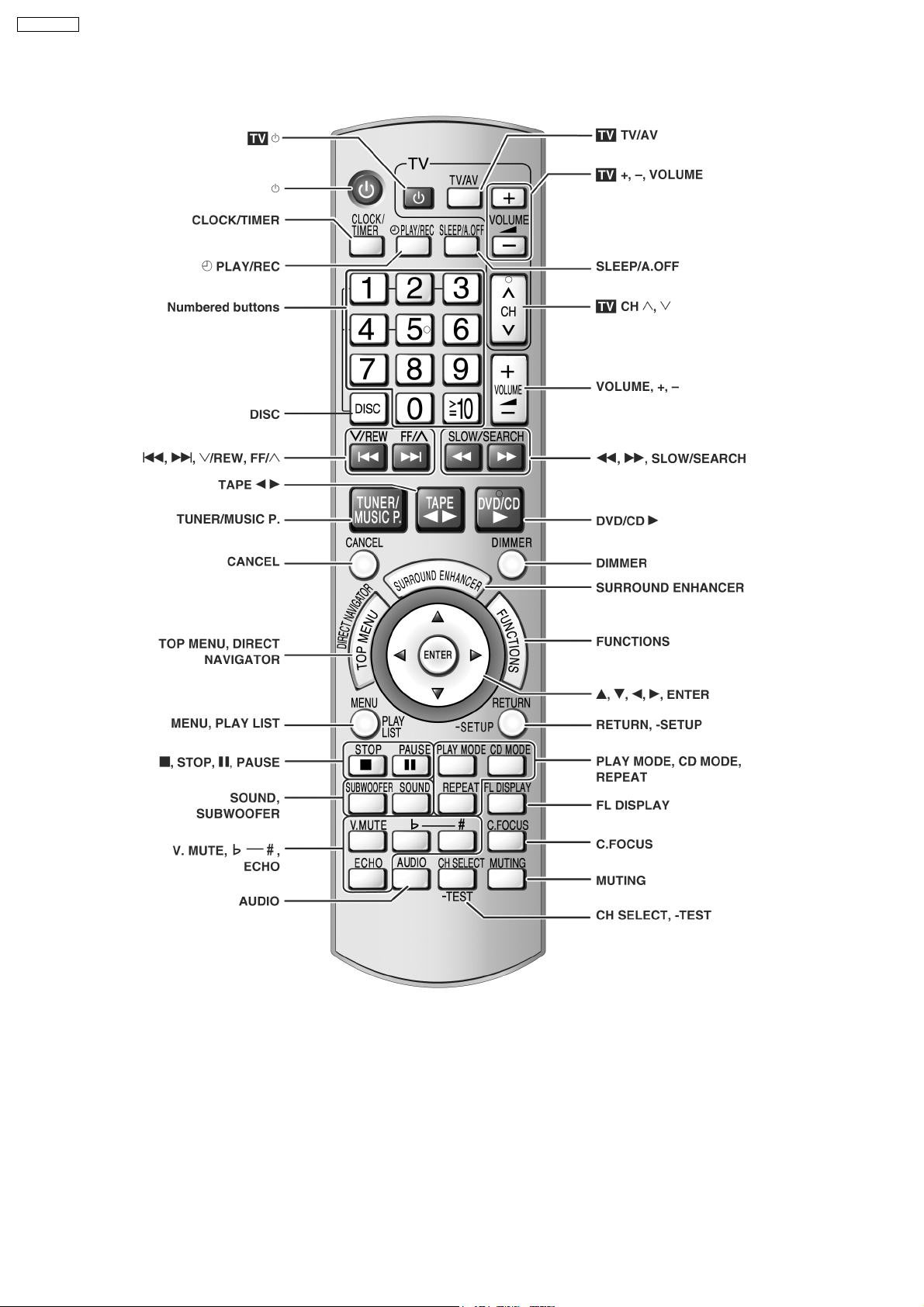
7.2. Remote Control Operation Control
14
7.3. Disc Information
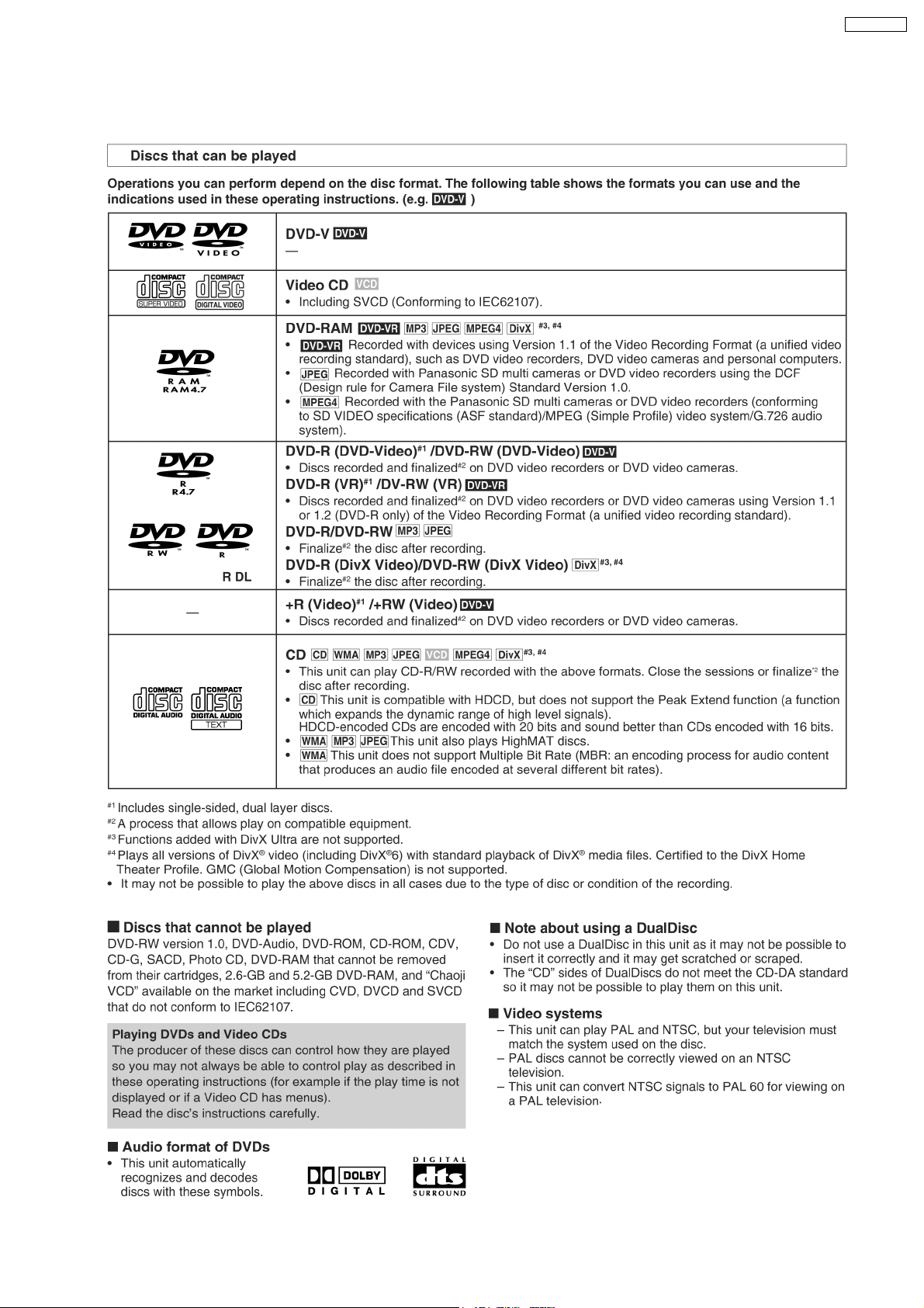
7.3.1. Disc Playability
SA-VK950EE
15
SA-VK950EE
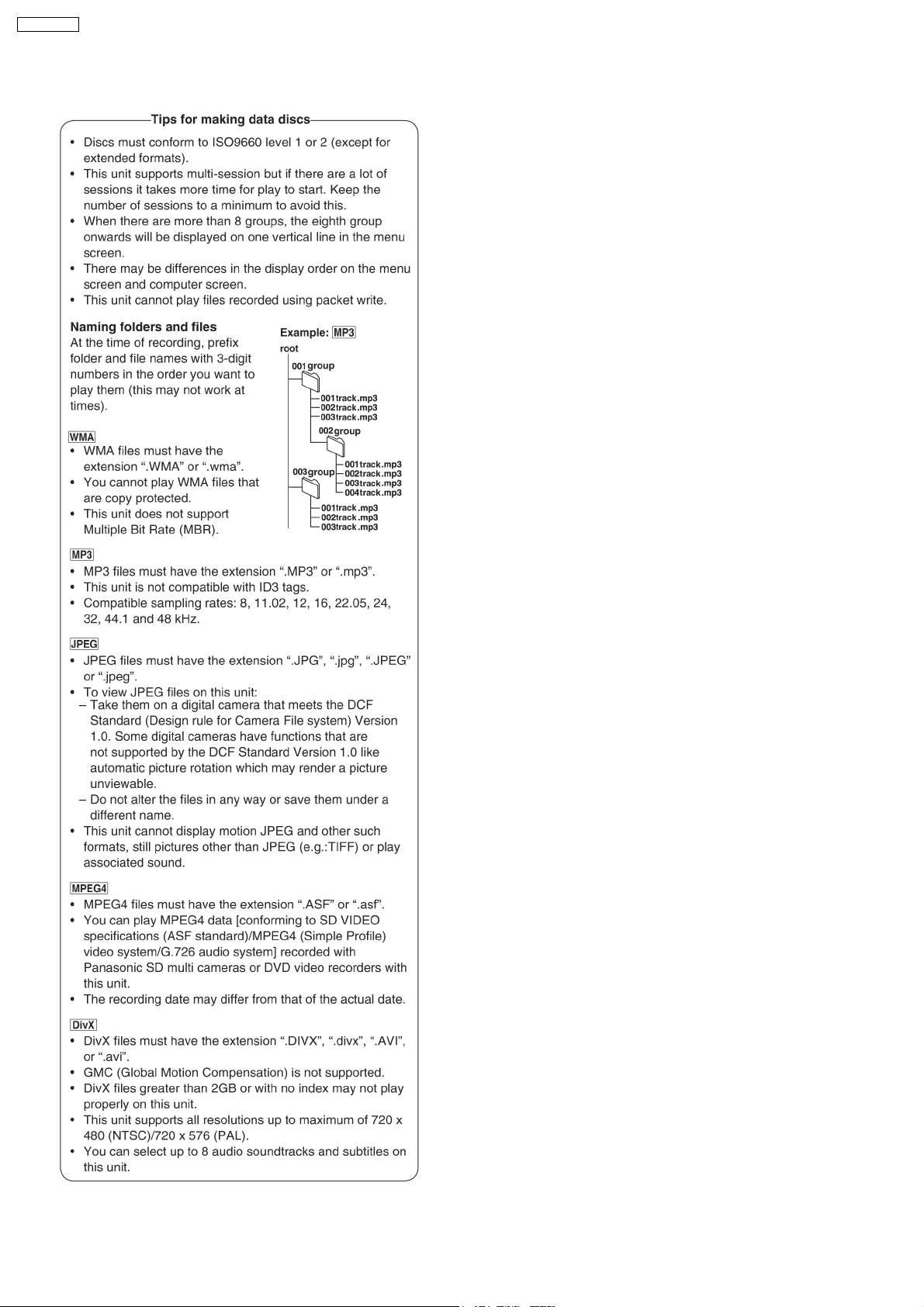
7.3.2. To Play MP3/ WMA and still Pictures (JPEG/ tiff)
16
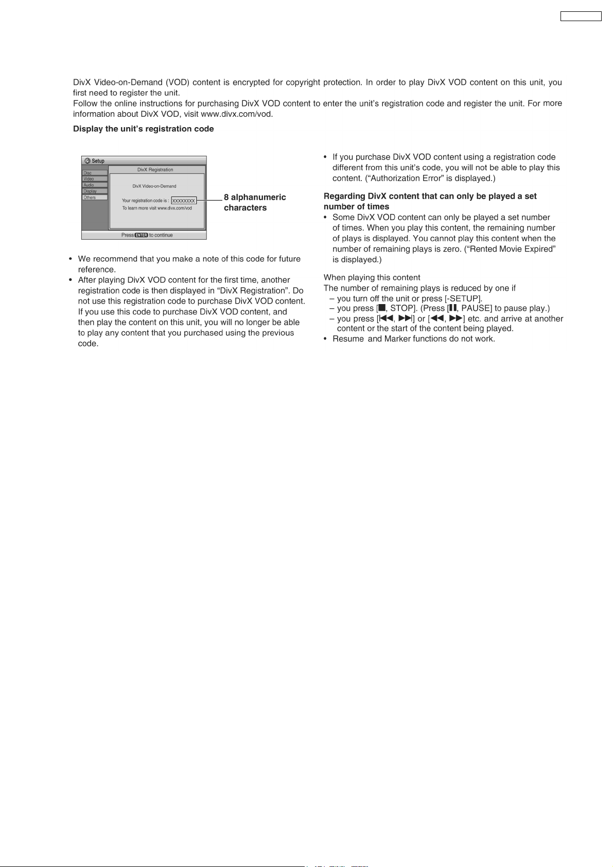
7.4. DivX VOD Content
SA-VK950EE
17
SA-VK950EE
8 New Features
8.1. CRS1D Mechanism Overview
18
SA-VK950EE
8.1.1. General Feature
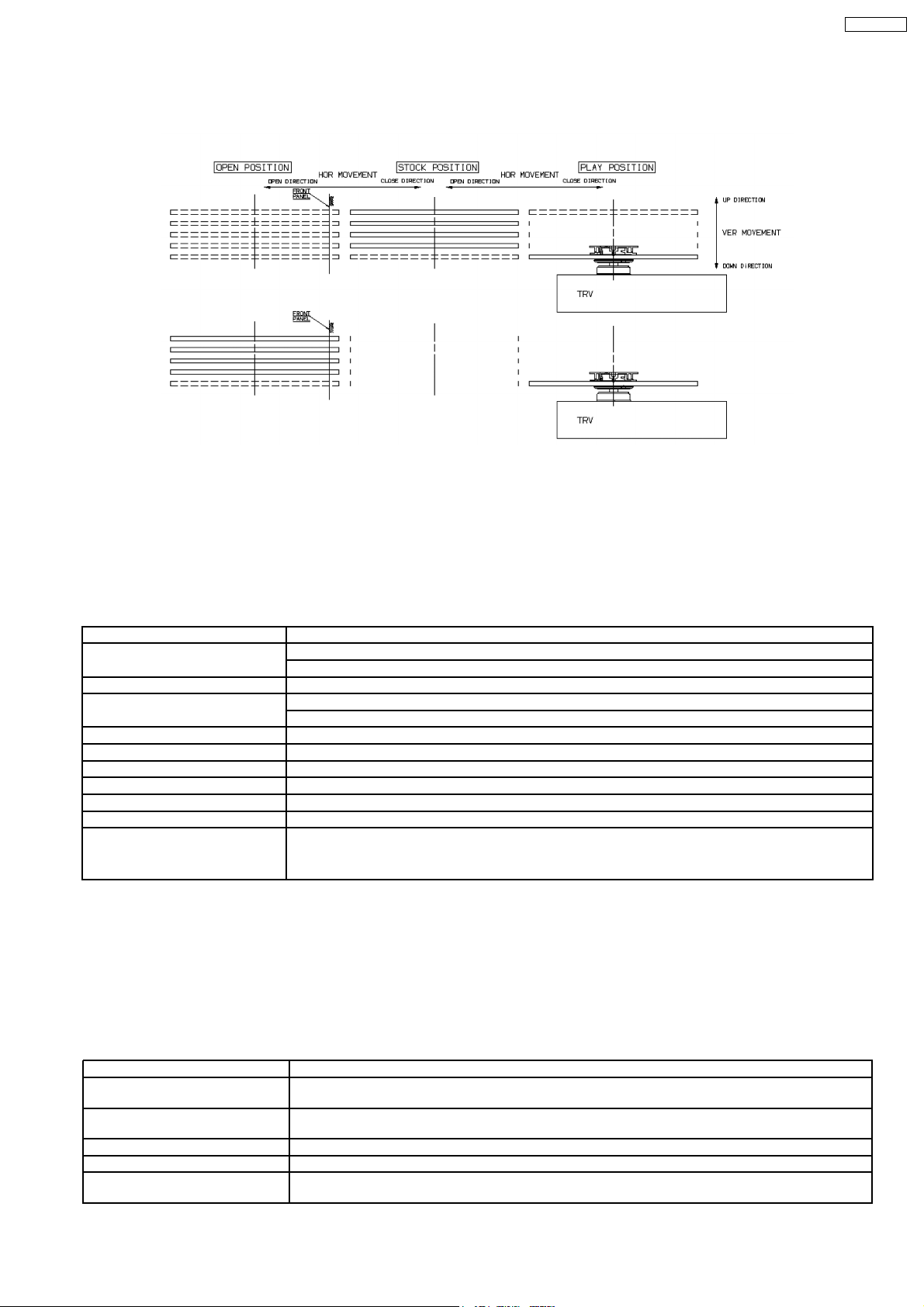
· This is a five disc changer mechanism for CD/DVD. The outline figure is shown below.
· The mechanism has "CHANGE WHILE PLAY" function. It open other trays for disc exchan ging while one tray is at PLAY
position performing recording or reproducing.
· The mechanism can quickly change all trays with "CHANGE ALL" function. All trays can be move to OPEN position with one
operation.
· There is no sensor to indicate presence of disc on any tray.
8.1.2. Hardware composition
· Below is the hardware components of the mechanism
Name Function
Open Switch (OPEN-SW) The switch is used to detect normal tray opening
The switch is used for detect tray being manually push/trigger when full open
Home Switch (HOME-SW) Is used to detect cam gear home position
Close Sensor (CLOSE-SENSOR) Used for normal single tray closing
Used to detect cam gear rotate to Play Driving position
Play Switch (PLAY-SW) Detect TRV clamping complete position
Stocking Switch (STOCK-SW) Detect tray completely transfer for play position to stocking position
UD Sensor (UD-SENSOR) Detect TRV vertical movement position
Top Switch (TOP-SW) Detect a default position of TRV vertical movement position
Driver IC To drive Motor
Motor Main driving source for changer
Plunger Switching the driving source from motor to:
1. Tray open/close
2. Drive tray to play/stock position and TRV vertical movement
8.1.3. Mechanism Operation
· This mechanism has the following state:
1. Driving of a tray to open/close
2. Up/down operation of a traverse performs a state changes of tray.
By using the plunger to lift/release of a switching gear, and the cam gear to lift/release the function gear the motor can be link
to several gear trains to perform various operations.
· The functions that can be perform in this mechanism are described as below:
Condition Explanation
Open current playing tray The state to change current playing disc. All tray will be open at once and current tray at PLAY position
Open All The state where all trays being driven to OPEN position. The disc can be taken in or out from tray to tray
Stock The state where the trays are stored in STOCK position
Play The state where one of the tray 5 trays is being driven to PLAY position and clamped by traverse unit
Play & Open Tray-* The state where one of the tray is in playing position performing recording or reproducing, other trays can
will be expose.
by close tray one by one from top to bottom.
be used (OPEN position) for disc exchanging without stopping the recording or reproducing process.
19
SA-VK950EE
Condition Explanation
Change The state when one of the opened tray being driven from OPEN position to STOCK position and other
Close All The state where all open trays will being driven from OPEN position to STOCK position, one by one from
Note: * represent tray number (from 1 ~ 5)
opened trays remain still at OPEN position.
top to bottom
8.1.4. New CD/DVD Mechanism (CRS1D)
Note:
This service manual does not contain the following information for the mention CD/DVD Mechanism drive:
· Schematic Diagram, Block Diagram and P.C.B. layout of CD/DVD Loading P.C.B.
· Part List for individual parts of the mechanism.
· Explode d View and Parts List for individual parts of the CD/DVD Mechanism drive.
Please refer to the original service manual (Order No. MD0603065A3) for the CD/DVD Mechanism Drive CRS1D.
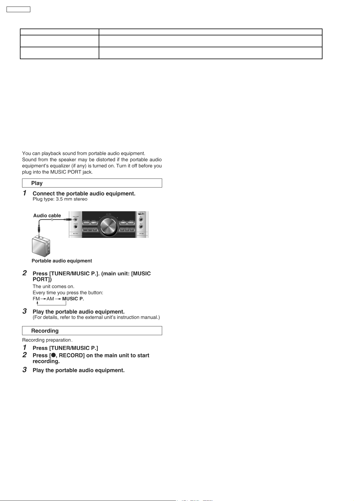
8.2. Music Port
With reference to page 31 of the operating instruction manual.
20

SA-VK950EE
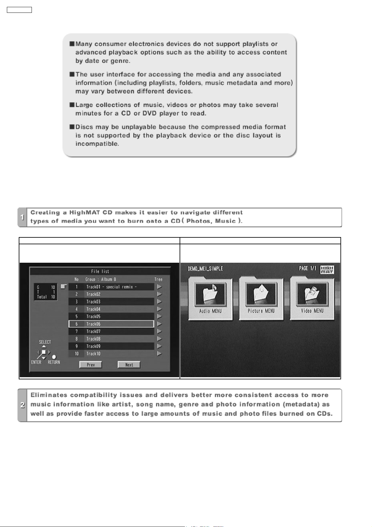
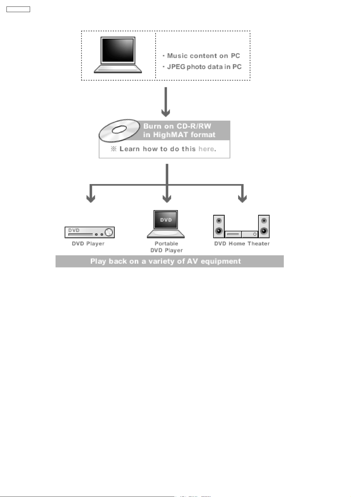
9 About HighMAT
9.1. What’s HighMAT?
Consumers worldwide are using PCs to create their own collections of music, photos and even video by burning them onto CDs.
But how these collections can be experienced across different devices can be confusing to navigate, time consum ing to access for
a DVD player, and be incomplete in terms of music information available to the customer.
HighMAT offers a solution to this growing consumer problem. HighMAT dramatically improves the digital media experience on
consumer electronic devices by delivering a simple, standardized approach that allows consumers who have created personal
collections of digital music, photography and video on their PC to:
>> Create a HighMAT CD or DVD which can be easily played back on consum er electronics devices such as CD and DVD players ,
and car stereos.
>> Move digital media files (using recordable media such as CD-R and CD-RW) between the PC and various playback devices
such as CD and DVD players.
A new standard for creating personal media on consumer electronic devices, HighMAT enable easier and more seamless
interoperability between Windows PCs and devices designed for your living room, or the car.
9.2. Why take advantage of HighMAT?
A Problem Defined:Toda y, when consumers create their own digital audio, video or photo collections on CD-R or other physical
formats, there are numerous, inconsistent ways that devices read the data. For the consumer, the playba ck experie nce can be
confusing:
21
SA-VK950EE
A Solution Created: HighMAT delivers a better digital media access experience by creating a standard approach for PCs to
structure digital media on various physical formats and for playback devices to read the data.
9.3. Benefits of HighMAT?
Conventional HighMAT
Even though DVD player is CD-R/RW compatible, the inconsistent ways
that various DVD players can read the music or photos files often leads
to a confusing and inconsistant playback experince.
HighMAT compatible products play content back with consistent
interface. This includes products which are JPEG compatible products
without HighMAT support.
22

SA-VK950EE
23
SA-VK950EE
HighMAT is now available for CD Burning and in Leading DVD PlayersHighMAT is a new technology that is now available in leading
software and consumer electronic devices to dramatically improve the digital media experience when you create homemade
CDsHighMAT delivers a simple, standardized way for PC software and consumer electronics devices to talk to each other and work
better together.
When you create your homemade CDs with software that supports HighMAT CD burning, and then play them back on a DVD
player that supports HighMAT, you get better, easier navigation. You get folders you can access with a single click of your DVD
player´s remote control. You can view important information about your music like full song names, artist titles, album names and
genre. And you can get faster startup on your home entertainment device.
To enjoy the benefits of HighMAT, all you need is software that supports HighMAT for CD burning of music or photos, as well as
a home entertainment device like a DVD player that supports HighMAT for playback. Always look for the HighMAT logo on your
software or home entertainment device to ensure it supports the HighMAT experience.
24
10 Self diagnosis and special mode setting
This unit is equipped with functions for checking and inspecting namely: Self-Diagnostic and Test Mode.
10.1. Service Mode Summary Table
The service modes can be activated by pressing various button combination on the player and remote control unit.
Below is the summary of major checking:
Player buttons Remote control unit buttons Application Note
STOP 0 Error code display (Refer to the section,
5 Jitter checking (Refer to the section
6 Region display and mode (Refer to the section
7 Micro-processor firmware version check
FUNCTIONS DVD laser drive current check
3 CD laser drive current check
Initial setting of laser drive current
“10.2.2 DVD Self
Diagnostic Function-Error
Code”).
“10.2.1 Service Mode
Table 1 for more
information”).
“10.2.1 Service Mode
Table 1 for more
information”).
SA-VK950EE
Initialization of the player (factory setting is restored.)
Used after replacement of micro-computer, FLASH ROM IC,
EEPROM and HDMI module.
8 Region and Firmware version display
ENTER DVD Module Reset (In Initialization Mode)
10.2. Service Mode Table 1
By pressing various button combin ations on the player and remote control unit can activate the various service modes for checking.
Special Note:
Due to the limitations of the no. characters that can be shown on FL Display, the “FL Display” button on the remote control unit
is used to show the following page. (Display 1 / Display 2).
10.2.1. Service Mode Table 1
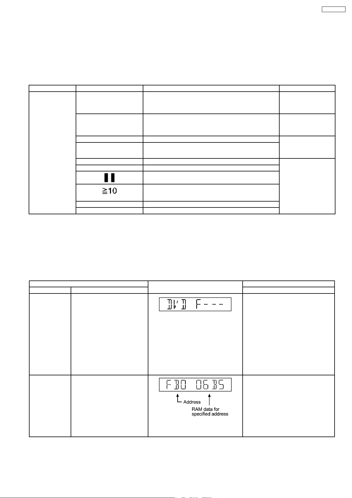
Item FL Display Key Operation
Mode Name Description Remote Control Key
Error code check Error code check.
ADSC internal
RAM data check
The latest error code stored in the
EEPROM IC is displayed.
ADSC internal RAM data check.
ADSC internal RAM data is read
out and displayed.
Error code (play_err) is expressed in the
following convention.
Error code = 0 x DAXX is expressed: DVDnn
UXX
Error code = 0 x DBXX is expressed: →
DVDnn HXX
Error code = 0 x DXXX is expressed: →
DVDnn FXXX
Error code = 0 x 0000 is expressed: →
DVDnn F--* “xx” denotes the error code →
In STOP (no disc) mode, press STOP
button on the player, and “0” button on the
remote control unit. *With pointing of cursor
up and down on display.
Cancelled automatically 5 seconds later.
To exit, press [POWER] button on main
unit or remote control.
In STOP (no disc) mode, press STOP
button on the player, and “1” or “2” button
on the remote control unit.
Press STOP or PLAY button to exit.
The value is shown in hexadecimal notation.
The above example shows the data in
ADSC address OFAh is 6901h.
25
SA-VK950EE
Item FL Display Key Operation
Mode Name Description Remote Control Key
CD laser drive
current
measurement
CD laser drive current
measurement.
CD laser drive current measured
and the result is displayed together
with the initial value stored in the
EEPROM IC.
1. For CD laser drive current mode
In STOP (no disc) mode, press STOP
button on the player, and “3” button on the
remote control unit.
Cancelled automatically 5 seconds later.
Press “FL Display” button on remote
control unit for next page (FL Display).
After the measurement, CD laser
emission is kept on. It is turned off
when POWER key is switched off.
(It is also turned off when POWER
button on the player is switched
2. The measurement Value (In decimal
notation)
off.)
Device Name Display the device name. 1.
2.
3.
Jitter check Jitter check.
1. For jitter measurement mode
Jitter rate is measured and
displayed.
Measurement is repeatedly done in
the cycle of one second. Read
error counter starts from zero upon
mode setting. When target block
data failed to be read out, the
counter advances by one
increment. When the failure is
caused by minor error, it may be
2.
corrected when retired to enable
successful reading. In this case,
the counter advances by one.
When the error persists even after
retry, the counter may jump by two
or more.
In STOP (no disc) mode, press STOP
button on the player, and “4” button on the
remote control unit. *With pointing of cursor
up and down on display.
Cancelled automatically 5 seconds later.
To exit, press [POWER] button on main
unit or remote control.
In STOP (no disc) mode, press STOP
button on the player, and “5” button on the
remote control unit.
Press STOP or OPEN button to exit.
Press “FL DISPLAY” button on remote
control unit for next page (FL Display).
Jitter rate is shown in decimal notation to
one place of decimal.
Focus drive value is shown in hexadecimal
notation.
Region display Region display & mode In STOP (no disc) mode, press STOP
button on the player, and “6” button on the
remote control unit.
Cancelled automatically 5 seconds later.
26
Item FL Display Key Operation
Mode Name Description Remote Control Key
Micro- processor
firmware version
display &
EEPROM
checksum display.
Micro-processor firmware version
display & EEPROM checksum
display.
In STOP (no disc) mode, press STOP
button on the player, and “7” button on the
remote control unit.
Cancelled automatically 5 seconds later.
Press “FL Display” button on remote
control unit for next page. (FL Display)
Refer to Section 10.3.1 for more
information.
SA-VK950EE
DVD module
firmware version
DVD module firmware version
display is on the FL Display.
display
Initialization Initialization.
User settings are cancelled and
player is initialized to factory
setting.
DVD Module
To reset DVD Module. In initialisation mode, press and hold STOP
Reset
DVD laser drive
current
measurement
DVD laser drive current
measurement.
DVD laser drive current is
measured and the result is
displayed together with the initial
value stored in the EEPROM IC.
After the measurement, DVD laser
emission is kept on. It is turned off
when POWER key is switched off.
(It is also turned off when POWER
button on the player is switched
off.)
1. For DVD laser drive current mode
2. The measurement value (In decimal
notation)
In STOP (no disc) mode, press STOP
button on the player, and “8” button on the
remote control unit.
Cancelled automatically 5 seconds later.
In STOP (no disc) mode, press STOP
button on the player, and
button
on the remote control unit.
button on the player followed by “Enter”
button on the remote control.
Cancelled automatically 5 seconds later.
In STOP (no disc) mode, press STOP
button on the player, and FUNCTIONS
button on the remote control unit.
Cancelled automatically 5 seconds later.
Press “FL Display” button on remote
control unit for next page (FL Display) on
values of DVD drive current.
Communication error display
Displays the frequency of
communication errors between
system control IC and mechanism
control IC.
The value denotes the current in decimal
notation.
The above example shows the initial current
is 20mA and the measured value is 20mA.
In STOP (no disc) mode, press STOP
button on the player, and “MENU” button
on the remote control unit.
Cancelled automatically 5 seconds later.
27
SA-VK950EE
Item FL Display Key Operation
Mode Name Description Remote Control Key
Initial setting of
laser drive current
Initial setting of laser drive current.
Initial current value for each of
DVD laser and CD laser is
separately saved in the EEPROM
IC.
1. For DVD/CD drive current mode
In STOP (no disc) mode, press STOP
button on the player, and PAUSE button on
the remote control unit.
Cancelled automatically 5 seconds later.
Press “FL Display” button on remote
control unit for next page (FL Display) on
values of laser drive current.
2. The measurement value (In decimal
notation)
The value denotes the current in decimal
notation. The above example shows the
initial current 20mA and 23mA for DVD
laser and CD laser respectively when the
laser is switched on.
ECC error display ECC decode error display. In STOP (no disc) mode, press STOP
button on the player, and TOP MENU
button on the remote control unit.
Cancelled automatically 5 seconds later.
Press “FL Display” button on remote
control unit for next page (FL Display) on
values of laser drive current.
Time 1 check Timer 1 check.
Laser operation time is measured
separately for DVD laser and CD
laser.
Press “FL Display” button for next
page of FL Display (to show CD
laser time).
Timer 1 reset Timer 1 reset.
Laser operation time of both DVD
laser and CD laser is reset all at
once.
Timer 2 check Timer 2 check.
Spindle motor operation timer.
Press “FL Display” button for next
page of FL Display.
Timer 2 reset Timer 2 reset.
Spindle motor operation timer.
Shown to the left is DVD laser time, and to
the right CD laser time.
Time is shown in 4 digits of decimal notation
in a unit of 10 hours.
“0000” will follow “9999”.
T1_0000/0000 (display1/display2)
Shown to the left is DVD laser time, and to
the right CD laser time.
Time is shown in 4 digits of decimal notation
in a unit of 10 hours.
Time is shown in 5 digits of decimal notation
in a unit of 10 hours.
“0000” will follow “9999”.
Time is shown in 5 digits of decimal notation
in a unit of 10 hours.
In STOP (no disc) mode, press STOP
button on the player, and “
” button on
the remote control unit.
Cancelled automatically 5 seconds later.
While display Timer 1 data, press STOP
button on the player, and “
“ button on
the remote control unit.
Cancelled automatically 5 seconds later.
In STOP (no disc) mode, press STOP
button on the player, and “
“ button on
the remote control unit.
Cancelled automatically 5 seconds later.
While display Timer 2 data, press STOP
button on the player, and “
“ button on
the remote control unit.
Cancelled automatically 5 seconds later.
28
10.2.2. DVD Self-Diagnostic Function Error Code
SA-VK950EE
Error
Code
F010 DVD Media disk A specification value is size from the
F020 DVD Media disk There is no TT_SRPT. (RLBN is 0). Press [ ] on main
F021 DVD Media disk The number of TT_SRP is 0. Press [ ] on main
F022 DVD Media disk A specification value. It is size from the
F023 DVD Media disk VTSN or in agreement with VTS_TTN.
F024 DVD Media disk A specification value. It is size from
F030 DVD Media disk The number of TTU_SRP is 0. Press [ ] on main
F031 DVD Media disk A specification value. It is size from the
Diagnosis Contents Description of error Automatic FL Display Remarks
PARENTAL LOCK value of the
appointed country.
number of TT_SRP.
There is no SRP.
TT_SRP. PTT_Ns
number of TTU_SRP.
Press [ ] on main
unit for next error.
unit for next error.
unit for next error.
Press [ ] on main
unit for next error.
Press [ ] on main
unit for next error.
Press [ ] on main
unit for next error.
unit for next error.
Press [ ] on main
unit for next error.
F040 DVD Media disk The number of SRP1 is 0. Press [ ] on main
F041 DVD Media disk The number of PGCI_SRP is 0. Press [ ] on main
F042 DVD Media disk A specification value. It is size from the
number of PGCI_SRP.
F043 DVD Media disk It is in agreement with Menu ID. There is
no PGCI_SRP.
F050 DVD Media disk The number of TMAP_SRP is 0. Press [ ] on main
F051 DVD Media disk A specification value. It is size from the
number of TMAP_SRP.
F052 DVD Media disk Specification TMAP_SA is 0. Press [ ] on main
F053 DVD Media disk The number of MAP_EN is 0. Press [ ] on main
unit for next error.
unit for next error.
Press [ ] on main
unit for next error.
Press [ ] on main
unit for next error.
unit for next error.
Press [ ] on main
unit for next error.
unit for next error.
unit for next error.
F060 DVD Media disk Although C_POSIT exists, it is in PGC.
There is no PGMAP.
F061 DVD Media disk Although C_POSIT exists, it is in PGC.
There is no PGMAP.
29
Press [ ] on main
unit for next error.
Press [ ] on main
unit for next error.
SA-VK950EE
Error
Diagnosis Contents Description of error Automatic FL Display Remarks
Code
F062 DVD Media disk A specification value inside of PGC. It is
size from the number of PGes.
F063 DVD Media disk Although C_POSIT exists, it is in PGC.
There is no C_PBIT.
F064 DVD Media disk Although C_POSIT exists, it is in PGC.
The number of PGes is 0.
Press [ ] on main
unit for next error.
Press [ ] on main
unit for next error.
Press [ ] on main
unit for next error.
F065 DVD Media disk Specification A cell number is 0.‘ Press [ ] on main
unit for next error.
F066 DVD Media disk A specification value inside of PGC. It is
size from the number of Cell(s).
Press [ ] on main
unit for next error.
F067 DVD Media disk A blocked cell is present. Press [ ] on main
unit for next error.
F070 DVD Media disk There is no NV_PACK data. Press [ ] on main
unit for next error.
F080 DVD Media disk Under reference. There is no Cell
number.
Press [ ] on main
unit for next error.
F0E0 DVD Media disk For [used as a DFD object] a user guide.
A PGC control file < impossible.
F0E1 DVD Media disk DFD main microcomputer. Compatibility
with a DFD type < download is
Press [ ] on main
unit for next error.
Press [ ] on main
unit for next error.
impossible.
F0E2 DVD Media disk DFD download start. PGC reproduction
error.
F0E3 DVD Media disk Waiting for the completion of DFD
download. PGC reproduction error.
Press [ ] on main
unit for next error.
Press [ ] on main
unit for next error.
F0E4 DVD Media disk At the time of DFD download AVDEC. Press [ ] on main
unit for next error.
F0E5 DVD Media disk It is the farm file lead error at the time of
DFD download.
F0E6 DVD Media disk DFD alteration check error of the read
firmware.
F0F0 DVD Media disk There is no farm file used as a DFD
object and it is downloading needlessly.
Press [ ] on main
unit for next error.
Press [ ] on main
unit for next error.
Press [ ] on main
unit for next error.
F0F1 DVD Media disk The firware which is in agreement with
DFD download conditions <
unnecessary.
F103 Illegal highlight Position Big possibility of disc specification
violation during highlight display
F4FF Force initialize failure
Timeout when force initialization fails Press [ ] on main
(time out)
30
Press [ ] on main
unit for next error.
Press [ ] on main
unit for next error.
unit for next error.
 Loading...