

Panasonic SA-HT885WGC, SA-HT885WGS, SA-HT885WEG Service Manual
lGeneral
Power Source:
A
C 110/127/220-230/240V,
50/60Hz
Power consumption: 25 W
Dimensions (W×H×D): 430×60×348.3 mm
Mass: 2.7 kg
lGeneral (For digital transmitter and receiver)
Power Source:
A
C 110-127/220-240V, 50/60
Hz
Power consumption:
Digital transmitter
Digital receiver
0.3 W
36 W
Dimensions (W×H×D):
Digital transmitter
Digital receiver
97×47.5×8.5 mm
103×215×178 mm
Mass:
Digital transmitter
Digital receiver
0.03 kg
2.3 kg
Wireless module:
Frequency range
No. of channels
Bandwidth/Channel
RF Output Power
RF Output Impedance
2.402-2.480 GHz
79
1MHz
14dBm (max)
50Ω
© 2005 Panasonic AVC Networks Singapore Pte.
Ltd. All rights reserved. Unauthorized copying and
distribution is a violation of law.
SA-HT885WGC
SA-HT885WGS
Colour
(S).......................Silver Type
Type of Emissions :
Data Rate
1 Mbps
lAmplifier section
RMS Output Power: Dolby Digital Mode
lTotal RMS Dolby Digital
mode Power:
700 W
At 1kHz and total harmonic of 10%
lFront: 60 W/ Channel (6Ω)
lCenter: 220 W/ Channel (6Ω)
lSurround: 60 W/ Channel (6Ω)
At 100Hz and total harmonic of 10%
lActive subwoofers: 240 W/ Channel (4Ω)
PMPO: 6000 W
DIN Output Power: Dolby Digital Mode:
lTotal DIN Dolby Digital mode Power:
450 W
At 1kHz and total harmonic of 1%
lFront: 40 W/ Channel (6Ω)
lCenter: 140 W/ Channel (6Ω)
lSurround: 40 W/ Channel (6Ω)
At 100Hz and total harmonic of 1%
lSubwoofer: 150 W/ Channel (4Ω)
lAmplifier section (For Wireless Receiver)
RMS Output Power: Dolby Digital Mode
At 1kHz and total harmonic of 10%
DVD Home Theater Sound System
Specifications
ORDER NO.MD0510385C3

lSurround: 60 W/ Channel (6Ω)
PMPO: 1000 W
lFM tuner section
Frequency Range: 87.5-108.0MHz
(50kHz in step)
Sensitivity: 2.5µV (IHF)
S/N 26dB 2.2µV
Antenna Terminal: 75Ω (non balance)
lAM tuner section (AM/MW)
Frequency Range:
522-1629kHz (9kHz in step)
520-1630kHz (10kHz in step)
AM Sensitivity S/N 20dB at
999kHz:
560µV/m
Phone Jack:
Terminal: Stereo 3.5mm jack
MIC Jack:
Sensitivity: 0.7 mv 1.2kΩ
Terminal: Mono 6.3 mm jack (2 systems)
lDisc section
Discs played [8 cm or 12 cm]:
(1) DVD-RAM (DVD-VR compatible, JPEG formatted discs,
MPEG4, DivX)
(2) DVD-Audio
(3) DVD-Video
(4) DVD-R, DVD-RW (DVD-Video compatible, DivX, DVD-VR
compatible)
+R, +RW (Video compatible)
(5) CD-Audio (CD-DA)
(6) Video CD
(7) SVCD (Conforming to IEC62107)
(8) CD-R/CD-RW (CD-DA, Video-CD, SVCD, MP3, WMA, JPEG
formatted discs, MPEG4, DivX, HighMAT Level 2)
(9) MP3/WMA
lMaximum number of recognizable audio, picture and video
contents and groups:
4000 audio, picture and video
contents and 400 groups
lMPEG-1 Layer 3, MPEG-2 Layer 3
lWIndows Media Audio Ver.9.0 L3
Not compatible with multiple Bit Rate (MBR)
(10) DivX
lDivX 3.11,4.x, 5.x
GMC (Global Motion Compensation) is not supported.
lMaximum number of recognizable audio, picture and video
contents and groups:
4000 audio, picture and video
contents and 400 groups
(11) MPEG4
lMaximum number of recognizable audio, picture and video
contents and groups:
4000 audio, picture and video
contents and 400 groups
lData recorded with Panasonic SD multi cameras or DVD
video recorders.
Comforming to SD VIDEO specifications (ASF standard)/
MPEG4 (Simple Profile) video system/G.7 26 audio system.
(12) JPEG
lMaximum number of recognizable audio, picture and video
contents and groups:
4000 audio, picture and video
contents and 400 groups
lExif Ver 2.1 JPEG Baseline files
lPicture resolution: between 160 x 120 and 6144 x 4096
pixels (sub sampling is 4:2:2 or 4:2:0)
(13) HighMAT Level 2 (Audio and lmage)
Pick up:
Wavelength:
lCD: 785nm
lDVD: 662nm
Laser power:
CLASS 2/ CLASS 3A
Audio output (DISC):
Number of channels:
5.1 ch (FL, FR, C, SL, SR,
SW)
Audio performance (measured at REC OUT terminal):
Frequency response:
DVD (linear audio): 10 Hz-22 kHz (48 kHz
sampling)
10 Hz-44 kHz (96 kHz
sampling)
DVD-Audio:
10 Hz-88 kHz (192 kHz
sampling)
CD-Audio: 10 Hz-20 kHz
S/N ratio:
CD-Audio:
95 dB
Dynamic range:
DVD (linear audio): 95 dB
CD-Audio: 93 dB
Total harmonic distortion:
CD-Audio: 0.005 %
lVideo section
V
ideo system:
Signal system: PAL 625/50, PAL 525/60,
NTSC
Composite video output:
Output level:
1 Vp-p (75 Ω)
Terminal: Pin jack (1 system)
S-video output:
Y
output level:
1 Vp-p (75 Ω)
C output level: PAL; 0.3Vp-p (75 Ω)
NTSC; 0.286 Vp-p (75 Ω)
Terminal S terminal (1 system)
Component video output (480P/480I):
NTSC: 525(480)p/525(480)i,
PAL: 625(576)p/625(567)i:
Y
output level: 1 Vp-p (75 Ω)
PBoutput level: 0.7 Vp-p (75 Ω)
PRoutput level: 0.7 Vp-p (75 Ω)
Terminal: Pin jack (Y: green, PB: blue,
P
R
: red) (1 system)
Note:
2
SA-HT885WGC / SA-HT885WGS
1. Specifications are subject to change without notice.
Mass and dimensions are approximate.
2. Total harmonic distortion is measured by the digital spectrum
analyzer.
Solder:
This model uses lead free solder (PbF).
1 Use of Active Subwoofer 5
1.1. Checking Player when Active Subwoofer is not used
5
2 Safety Precaution s
6
2.1. GENERAL GUIDELINES
6
3 Prevention of Electro Static Discharge (ESD) to
Electrostatically Sensitive (ES) Devices
6
4 Before Repair and Adjustment (Using Active Subwoofer)
7
5 Protection Circuitry
7
6 Precaution of Laser Diode
8
7 About Lead Free Solder (PbF)
8
8 General Description
9
8.1. Operating instructions
9
8.2. Disc information
10
8.3. Using of Receiver Unit (SH-FX50)
12
8.4. About HighMAT
13
9 Accessories
18
10 Caution for AC Cord
19
11 Handling Precaution s for Optical Pickup Unit
20
11.1. Cautions to Be Taken in Handling the Optical Pickup Unit
20
11.2. Cautions to Be Taken When Replacing the Optical Pickup
20
11.3. Grounding for electrostatic breakdown prevention
20
12 Disassembly and Main Component Replacement Procedure
22
12.1. Disassembly Procedure
22
12.2. Main Components and P.C.B. Locations.
23
12.3. Disassembling the Top Cabinet
24
12.4. Disassembling the Lid assembly (When taking out disc
manually)
24
12.5. Disassembling the Front Panel
25
12.6. Disassembling the FL P.C.B., Volume P.C.B. and MIC
P.C.B.
25
12.7. Disassembling the DVD mechanism Unit
25
12.8. Disassembling the DVD Module P.C.B.
26
12.9. Disassembling the Rear panel
26
12.10. Disassembling Main P.C.B.
26
12.11. Service Position
27
13 Assembling and disassembling the DVD mechanism Unit
28
13.1. Disassembly Procedure
28
13.2. Traverse Unit
28
13.3. Tray Unit
29
13.4. Loading section
30
13.5. Tray Loading P.C.B.
31
13.6. Optical Pickup Unit
31
13.7. Traverse Motor and Spindle Motor
33
CONTENTS
Page Page
3
SA-HT885WGC / SA-HT885 WGS

14 Optical Pick-up Self-Diagnosis and Replacement Procedure
35
14.1. Optical Pickup Breakdown Diagnosis
35
14.2. Service Mode Table 1
36
14.3. DVD Self Diagnostic Function-Error Code
36
14.4. Service mode table 2
38
14.5. Sales demonstration lock function
40
14.6. Handling After Completing Repairs
40
15 Self-Diagnosis Function
41
15.1. Automatic Displayed Error Codes
41
15.2. Memorized Error Codes
41
16 Service Precautions
42
16.1. Recovery after the DVD player is repaired
42
16.2. Firmware version-up of the DVD player
42
17 Adjustment Procedure
43
17.1. Service Tools and Equipment
43
17.2. Important points in adjustment
43
17.3. Storing and Handling Test Discs
43
17.4. Optical adjustment
44
18 Abbreviati ons 45
19 Voltage Chart
47
19.1. DVD Module P.C.B.
47
19.2. Main P.C.B.
48
19.3. FL P.C.B. & MIC P.C.B & Tray Loading P.C.B.
49
20 Wave Form Chart
50
21 Schematic Diagram Notes
51
22 Block Diagram
53
23 Schematic Diagram
59
24 Printed Circuit Board Diagram
69
25 Wiring Connection Diagram
73
26 Illustration of IC's, Transistors and Diodes
75
27 Terminal Function of ICs
76
27.1. IC2018 (C2CBJG000672): System control
76
28 Parts Location and Replacement Parts List
77
28.1. Loading Mechanism, Traverse Unit & Cabinet
78
28.2. Component Parts List
81
28.3. Packing Materials & Accessories Parts List
91
28.4. Packaging
91
4
SA-HT885WGC / SA-HT885 WGS
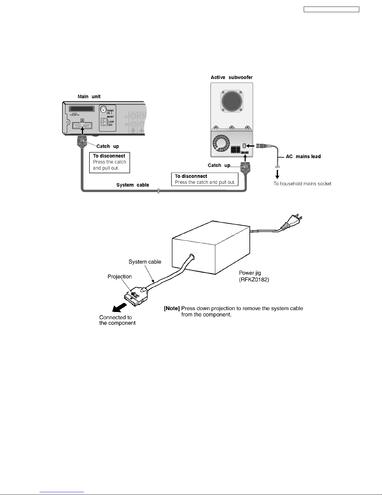
1 Use of Active Subwoofer
1.1. Checking Player when Active Subwoofer is not used
1. This unit uses the active subwoofer to supply the power of the component, and the active subwoofer should be connected to
the component to check operational conditions of the component.
2. If the active subwoofer is not available due to repair of the unit, use the following equipment.
Jig product numbe r: RFKZ0182 (110V, 127V, 220V, 230V-240V for overseas domestic use)
5
SA-HT885WGC / SA-HT885 WGS
2.1.1. LEAKAGE CURRENT COLD
CHECK
1. Unplug the AC cord and connect a jumper between the two
prongs on the plug.
2. Measure the resistance value, with an ohmmeter, between
the jumpered AC plug and each exposed metallic cabinet
part on the equipment such as screwheads, connectors,
control shafts, etc. When the exposed metallic part has a
return path to the chassis, the reading should be between
1MΩ and 5.2MΩ.
When the exposed metal does not have a return path to
the chassis, the reading must be
.
Figure 1
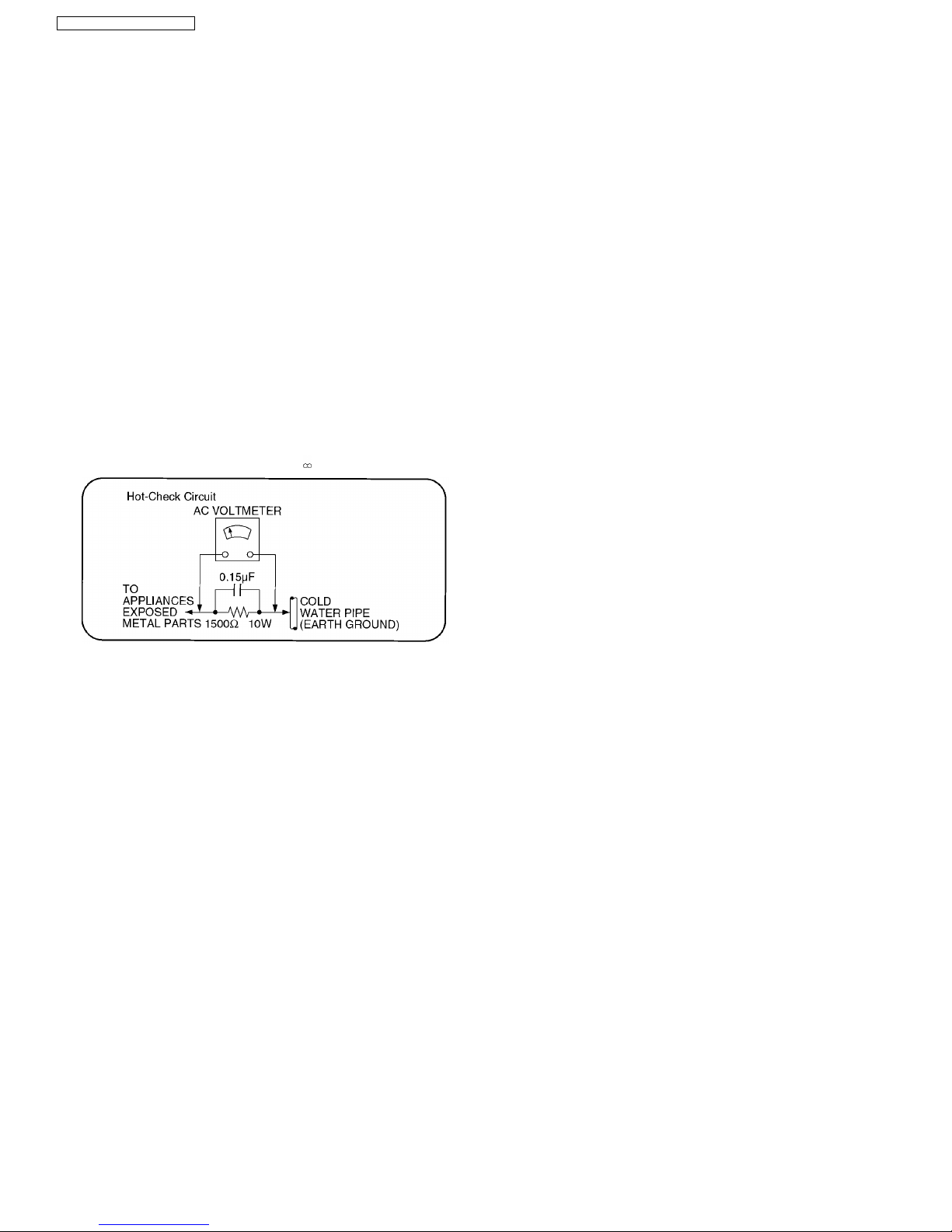
2.1.2. LEAKAGE CURRENT HOT CHECK
(See Figure 1 .)
1. Plug the AC cord directly into the AC outlet. Do not use an
isolation transformer for this check.
2. Connect a 1.5kΩ, 10 watts resistor, in parallel with a 0.15µF
capacitors, between each exposed metallic part on the set
and a good earth ground such as a water pipe, as shown in
Figure 1.
3. Use an AC voltmeter, with 1000 ohms/volt or more
sensitivity, to measure the potential across the resistor.
4. Check each exposed metallic part, and measure the
voltage at each point.
5. Reverse the AC plug in the AC outlet and repeat each of the
above measurements.
6. The potential at any point should not exceed 0.75 volts
RMS. A leakage current tester (Simpson Model 229 or
equivalent) may be used to make the hot checks, leakage
current must not exceed 1/2 milliamp. In case a
measurement is outside of the limits specified, there is a
possibility of a shock hazard, and the equipment should be
repaired and rechecked before it is returned to the
customer.
2 Safety Precautions
2.1. GENERAL GUIDELINES
1. When servicing, observe the original lead dress. If a short circuit is found, replace all parts which have been overheated or
damaged by the short circuit.
2. After servicing, see to it that all the protective devices such as insulation barriers, insulation papers shields are properly
installed.
3. After servicing, carry out the following leakage current checks to prevent the customer from being exposed to shock hazards.
3 Prevention of Electro Static Discharge (ESD) to
Electrostatically Sensitive (ES) Devices
Some semiconductor (solid state) devices can be damaged easily by static electricity. Such components commonly are called
Electrostatically Sensitive (ES) Devices. Examples of typical ES devices are integrated circuits and some field-effect transistors and
semiconductor "chip" components. The following techniques should be used to help reduce the incidence of component damage
caused by electro static discharge (ESD).
1. Immediately before handling any semiconductor component or semiconductor-equipped assembly, drain off any ESD on your
body by touching a known earth ground. Alternatively, obtain and wear a commercially available discharging ESD wrist strap,
which should be removed for potent ial shock reasons prior to applying power to the unit under test.
2. After removing an electrical assembly equipped with ES devices, place the assembly on a conductive surface such as
aluminum foil, to prevent electrostatic charge buildup or exposure of the assembly.
3. Use only a grounded-tip soldering iron to solder or unsolder ES devices.
4. Use only an anti-static solder removal device. Some solder removal devices not classified as "anti-static (ESD protected)" can
generate electrical charge sufficient to damage ES devices.
5. Do not use freon-propelled chemicals. These can generate electrical charges sufficient to damage ES devices.
6. Do not remove a replacement ES device from its protective package until immediately before you are ready to install it. (Most
replacement ES devices are packaged with leads electrically shorted together by conductive foam, aluminum foil or comparable
conductive material).
7. Immediately before removing the protective material from the leads of a replacement ES device, touch the protective material
to the chassis or circuit assembly into which the device will be installe d.
6
SA-HT885WGC / SA-HT885 WGS

Caution
Be sure no power is applied to the chassis or circuit, and observe all other safety precautions.
8. Minimize bodily motions when handling unpackaged replacement ES devices. (Otherwise harmless motion such as the
brushing together of your clothes fabric or the lifting of your foot from a carpeted floor can generate static electricity (ESD)
sufficient to damage an ES device).
4 Before Repair and Adjustment (Using Active Subwoofer)
Disconnect AC power, discharge Power Supply Capacitors C546~C549 through a 10 Ω, 10 W resistor to ground.
DO NOT SHORT-CIRCUIT DIRECTLY (with a screwdriver blade, for instance), as this may destroy solid state devices.
After repairs are completed, restore power gradually using a variac, to avoid overcurrent.
Current consumption at AC 220 - 240 V, 50 Hz in NO SIGNAL mode should be ~ 600 mA.
Current consumption at AC 110/127 V, 50/60Hz in NO SIGNAL mode should be ~1180 mA.
5 Protection Circuitry
The protection circuitry may have operated if either of the following conditions are noticed:
· No sound is heard when the power is turned on.
· Sound stops during a performance.
The function of this circuitry is to prevent circuitry damage if, for example, the positive and negative speake r connection wires are
“shorted”, or if speake r systems with an impedance less than the indicated rated impedance of the amplifier are used.
If this occurs, follow the procedure outlines below:
1. Turn off the power.
2. Determine the cause of the problem and correct it.
3. Turn on the power once again after one minute.
Note:
When the protection circuitry functions, the unit will not operate unless the power is first turned off and then on again.
7
SA-HT885WGC / SA-HT885 WGS
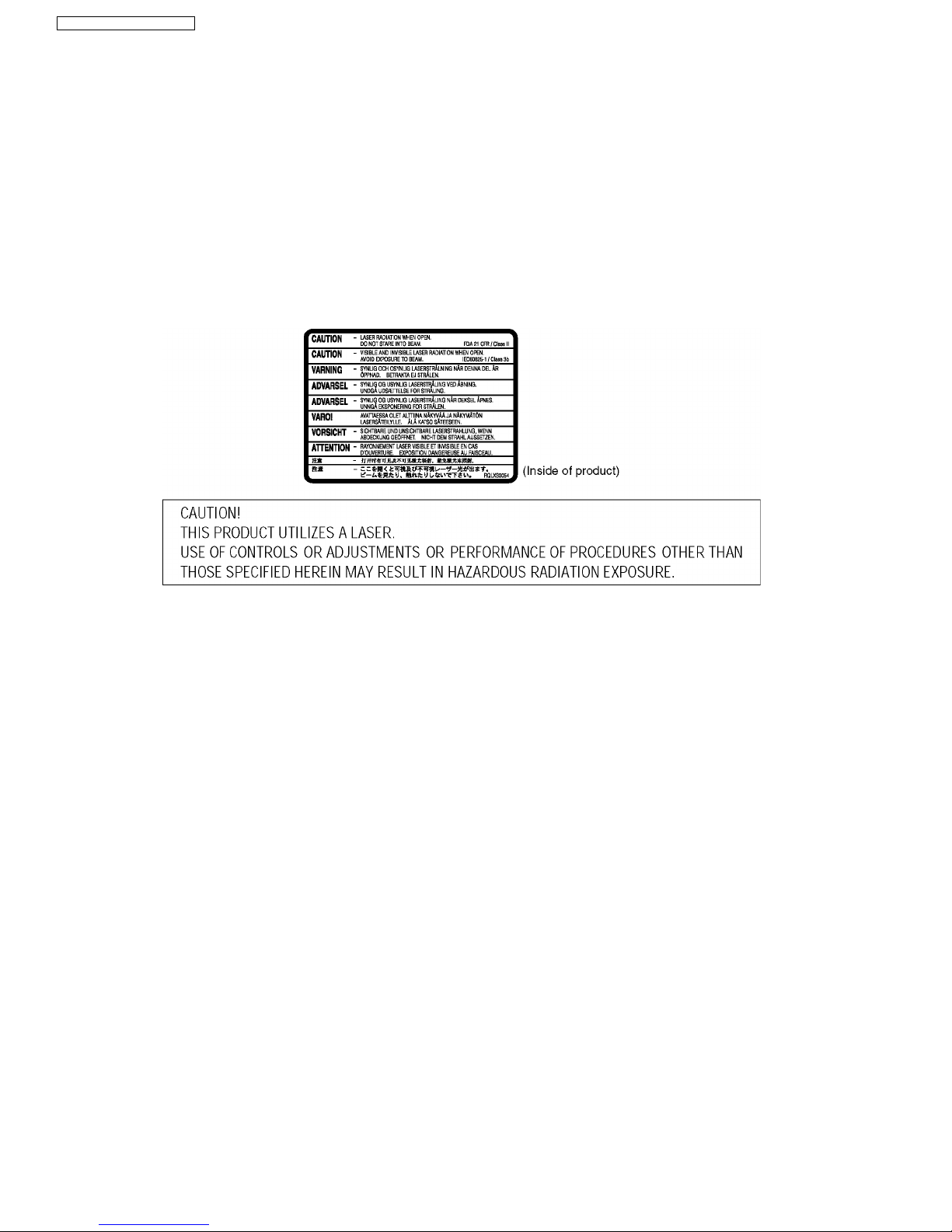
6 Precaution of Laser Diode
CAUTION :
This product utilizers a class 1 laser. Invisible laser radiation is emitted from the optical pick up lens.
When the unit is turned on:
Wavelength : 658nm/780nm
Maximum output radiation power from pick up : 100µW/VDE
Laser radiation from pick up unit is safety level, but be sure the followings:
1. Do not disassemble the optical pick up unit, since radiation from exposed laser diode is dangerous.
2. Do not adjust the variable resistor on the pick up unit. It was already adjusted.
3. Do not look at the focus lens using optical instruments.
4. Recommend not to look at pick up lens for a long time.
7 About Lead Free Solder (PbF)
Distinction of PbF PCB: PCBs (manufactured) using lead free solder will have a PbF stamp on the PCB.
Caution:
· Pb free solder has a higher melting point than standard solder; Typically the melting point is 50 - 70°F (30 - 40°C) higher.
Please use a high temperature soldering iron. In case of the soldering iron with temperature control, please set it to 700 ±
20°F (370 ± 10°C).
· Pb free solder will tend to splash when heated too high (about 1100°F/ 600°C).
When soldering or unsoldering, please completely remove all of the solder on the pins or solder area, and be sure to heat the
soldering points with the Pb free solder until it melts enough.
8
SA-HT885WGC / SA-HT885 WGS
8 General Description
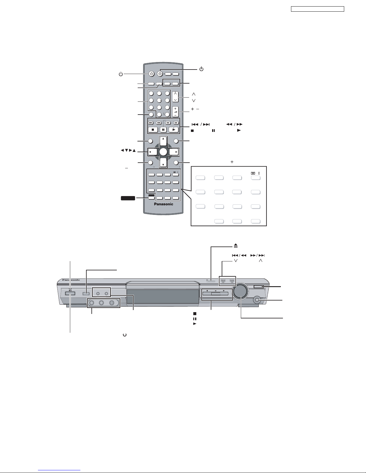
8.1. Operating instructions
SHIFT
TOP MENU
ENTER
FUNCTIONS/
TV VOL
FM MODE
INPUT SELECTOR PROGRESSIVE H.BASS
TUNE MODE FM MODE MEMORY
TUNING
DOWN
UP
PHONES
VOLUME
OPENCLOSE
VOLUME
CH
SKIP
SLOW/SEARCH
MENU
DIRECT
NAVIGATOR
TOP MENU
RETURN
FUNCTIONS
VCR
TV
TUNER/BAND
SUBWOOFER
LEVEL
SUPER SRND
H.BASS
C.FOCUS
SFC
PLAY MODE
TEST
CH SELECT
SETUP
MUTING
MIX 2CH
PL
ZOOM
MANU
QUICK OSD
AL SKIP
SUBTITLE
AUDIO
PLAY SPEED
QUICK REPLAY
ADVANCED
DISC REVIEW
FL DISPLAY REPEAT
SHIFT
ANGLE/PAGE
GROUP
AV SYSTEM
DVD/CD
PLAY
LIST
TV VOLTV VOL
ENTER
12
6
9
45
7
8
CANCEL
0
S 10
3
-/--
SLEEP
TV/AV
AUX
SUBWOOFER
LEVEL
SUPER SRND
H.BASS
C.FOCUS
SFC
PLAY MODE
TEST
CH SELECT
SETUP
MUTING
MIX 2CH
PL
ZOOM
MANU
QUICK OSD
AL SKIP
SUBTITLE
AUDIO
PLAY SPEED
QUICK REPLAY
SLEEP
ADVANCED
DISC REVIEW
FL DISPLAY REPEAT
ANGLE/PAGE
GROUP
STANDBY/ON INDICATOR
TUNING
REMOTE CONTROL
SIGNAL SENSOR
STANDBY/ON SWITCH
MIC, MIC LEVEL
[/I
I
]
/
/
MEMORY
RETURN/TV VOL
CANCEL
/AV SYSTEM
NUMBERED
BUTTONS
CH
CH
VOLUME
MENU
TV/AV
TUNER/BAND,
DVD/CD
AUX
(SKIP)
(SLOW/SEARCH)
(PLAY)
(STOP) (PAUSE)
TUNE MODE
INPUT SELECTOR
PHONES
VOLUME
OPEN/CLOSE
PROGRESSIVES/
H.BASS/H.BASS INDICATOR
MIN MAX
9
SA-HT885WGC / SA-HT885 WGS
8.2. Disc information
A process that allows play on compatible equipment.
This unit automatically recognizes
and decodes discs with these
symbols.
–This unit can play PAL and NTSC, but your television must match
the system used on the disc.
–PAL discs cannot be correctly viewed on an NTSC television.
–This unit can convert NTSC signals to PAL 60 for viewing on a PAL
television.
Recorded with devices using Version 1.1 of the Video Recording Format (a
unified video recording standard), such as DVD video recorders, DVD video
cameras, personal computers, etc.
—
—
Some DVD-Audio discs contain DVD-Video content.
To play DVD-Video content, select “Play as DVD-Video” in Other Me nu.
—
Discs recorded and finalized on D VD video recorders or DVD video cameras.
—
Discs recorded and finalized on D VD video recorders or DVD video cameras.
Video CD
—
SVCD
Conforming to IEC62107
CD
This unit is compatible with HDCD, but does not support the Peak Extend
function (a function which expands the dynamic range of high level signals).
HDCD-encoded CD’s sound better because they are encoded with 20 bits, as
compared with 16 bits for all other CD’s.
CD-R
CD-RW
—
This unit can play CD-R/RW (audio recording disc) recorded with the formats
on the left. Close the sessions or finalize the disc after recording.
WMA, MP3 or JPEG files only.
To play without using the HighMAT function, select “Play as Data Disc” in Other
Menu.
This unit does not support Multiple Bit Rate (MBR: a file that contains the
same content encoded at several different bit rates).
RAM
JPEG
DVD-A
DVD-V
DVD-V
DVD-RW (VR)
VCD
CD
VCD
CD
WMA
WMA
MP3
JPEG
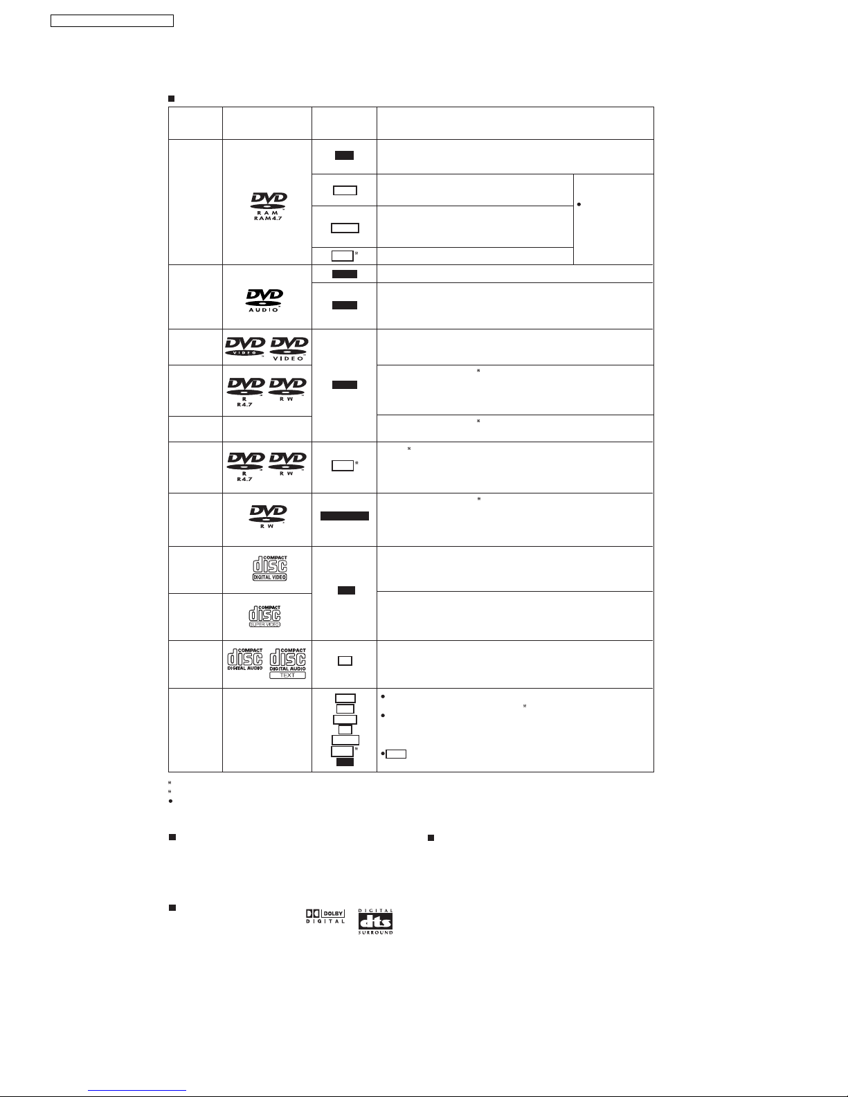
Discs that can be played
Disc
Logo
Indication in
these operating
instructions
Remarks
Recorded with Panasonic SD multi cameras or DVD
video recorders using the DCF (Design rule for Camera
File system) Standard Version 1.0.
Recorded with Panasonic SD multi cameras or DVD
video recorders [conforming to SD VIDEO
specifications (ASF standard)/MPEG4 (Simple Profile)
video system/G.726 audio system].
DVD-RAM
MPEG4MPEG4
MPEG4MPEG4
To play JPEG,
MPEG4 or DivX video
contents, select "Play
as Data Disc" in Other
Menu
DVD-Audio
DVD-Video
DVD-R
(DVD-Video)/
DVD-RW
(DVD-Video)
DVD-R
(DivX-Video)/
DVD-RW
(DivX-Video)
DVD-RW
(DVD-VR)
2
2
2
2
2
+R (Video)/
+RW (Video)
DivX
1
DivX
1
DivX
1
Finalize the disc after recording.
Discs recorded and finalized on DVD video recorders or DVD video cameras
using Version 1.1 of the Video Recording Format (a unified video recording
standard).
HighMAT discs
Created using DivX ver.3.11, 4.x, 5.x [DivX video system/MP3, Dolby Digital or MPEG audio system].
1
2
It may not be possible to play the above discs in all cases due to the type of discs, the condition of the recording, the recording method and how
the files were created.
Discs that cannot be played
Version 1.0 of DVD-RW, DVD-ROM, CD-ROM,CDV, CD-G, SACD
and Photo CD, DVD-RAM that cannot be removed from their
cartridge, 2.6-GB and 5.2-GB DVD-RAM and "Chaoji VCD" available
on the market including CVD, DVCD and SVCD that do not conform
to IEC62107.
Audio format of DVD's
Video systems
10
SA-HT885WGC / SA-HT885 WGS
11
SA-HT885WGC / SA-HT885 WGS
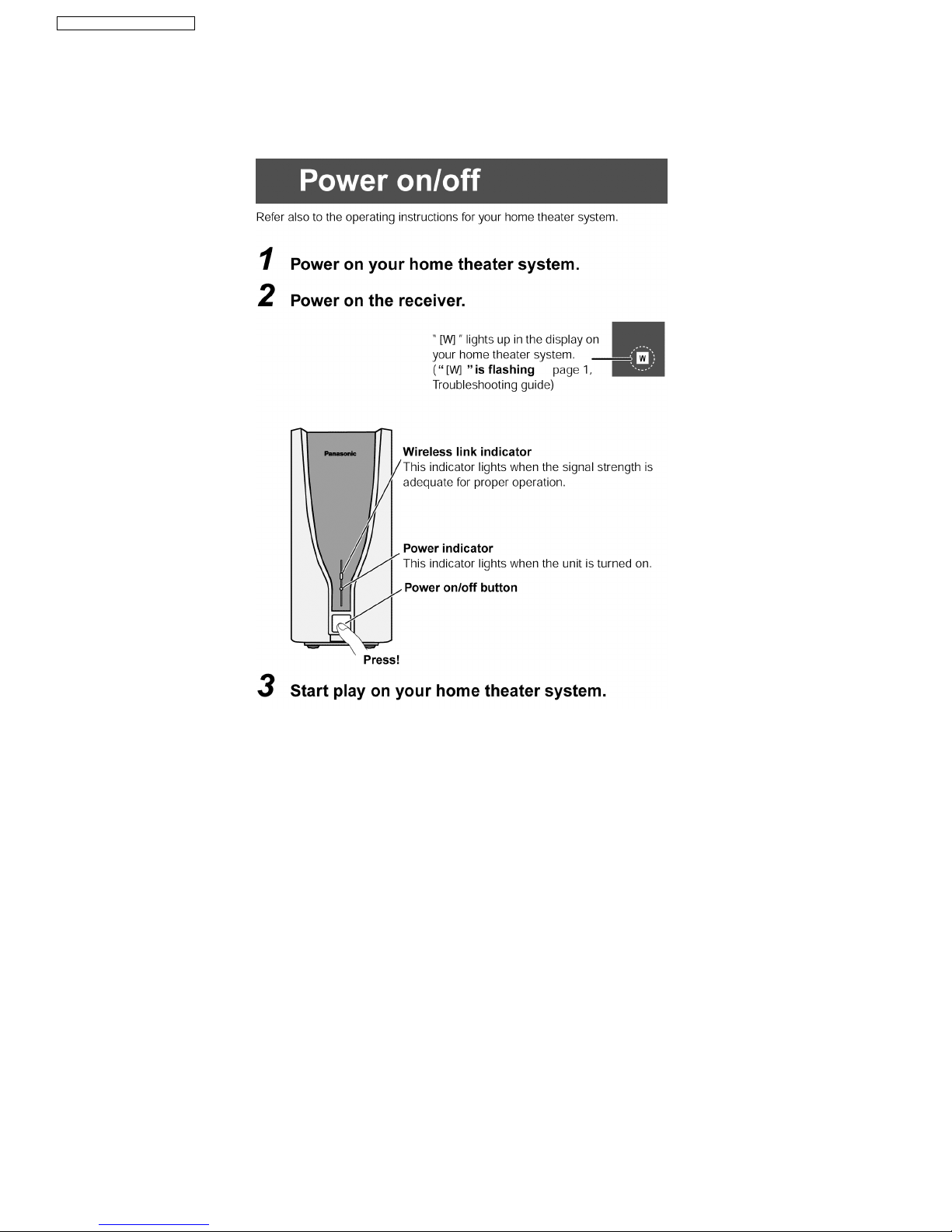
8.3. Using of Receiver Unit (SH-FX50)
· This model can be equipped with the digital transmitter and receiver to enjoy surround sound wirelessly..
8.3.1. Below is tips on using the digital receiver
12
SA-HT885WGC / SA-HT885 WGS
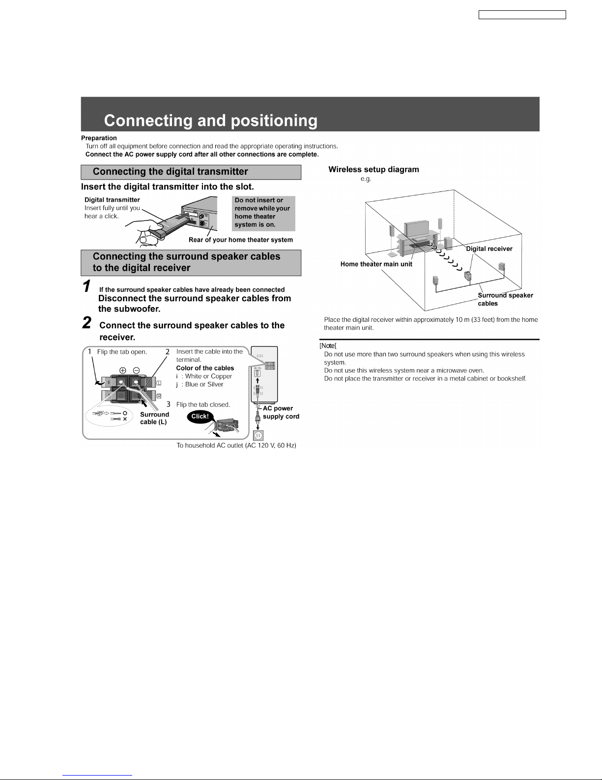
8.3.2. Tips of using digital transmitter
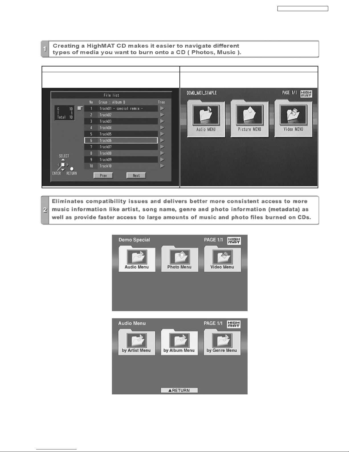
8.4. About HighMAT
8.4.1. What’s HighMAT?
Consumers worldwide are using PCs to create their own collections of music, photos and even video by burning them onto CDs.
But how these collections can be experienced across different devices can be confusing to navigate, time consuming to access for
a DVD player, and be incomplete in terms of music information available to the customer.
HighMAT offers a solution to this growing consumer problem. HighMAT dramatically improves the digital media experience on
consumer electronic devices by delivering a simple, standardized approach that allows consumers who have created personal
collections of digital music, photography and video on their PC to:
lCreate a HighMAT CD or DVD which can be easily played back on consum er electronics devices such as CD and DVD players,
and car stereos.
lMove digital media files (using recordable media such as CD-R and CD-RW) between the PC and various playba ck devices such
as CD and DVD players .
A new standard for creating personal media on consumer electronic devices, HighMAT enable easier and more seamless
interoperability between Windows PCs and devices designed for your living room, or the car.
13
SA-HT885WGC / SA-HT885 WGS

8.4.2. Why take advantage of HighMAT?
A Problem Defined:Today, when consumers create their own digital audio, video or photo collections on CD-R or other physical
formats, there are numerous, inconsistent ways that devices read the data. For the consumer, the playba ck experience can be
confusing:
A Solution Created: HighMAT delivers a better digital media access experience by creating a standard approach for PCs to
structure digital media on various physical formats and for playba ck devices to read the data.
14
SA-HT885WGC / SA-HT885 WGS
8.4.3. Benefits of HighMAT?
Conventional HighMAT
Even though DVD player is CD-R/RW compatible, the inconsistent ways
that various DVD players can read the music or photos files often leads
to a confusing and inconsistant playback experince.
HighMAT compatible products play content back with consistent
interface. This includes products which are JPEG compatible products
without HighMAT support.
15
SA-HT885WGC / SA-HT885 WGS
HighMAT is now available for CD Burning and in Leading DVD Players
HighMAT is a new technology that is now available in leading software and consumer electronic devices to dramatically improve
the digital media experience when you create homemade CDs
HighMAT delivers a simple, standardized way for PC software and consumer electronics devices to talk to each other and work
better together.
16
SA-HT885WGC / SA-HT885 WGS

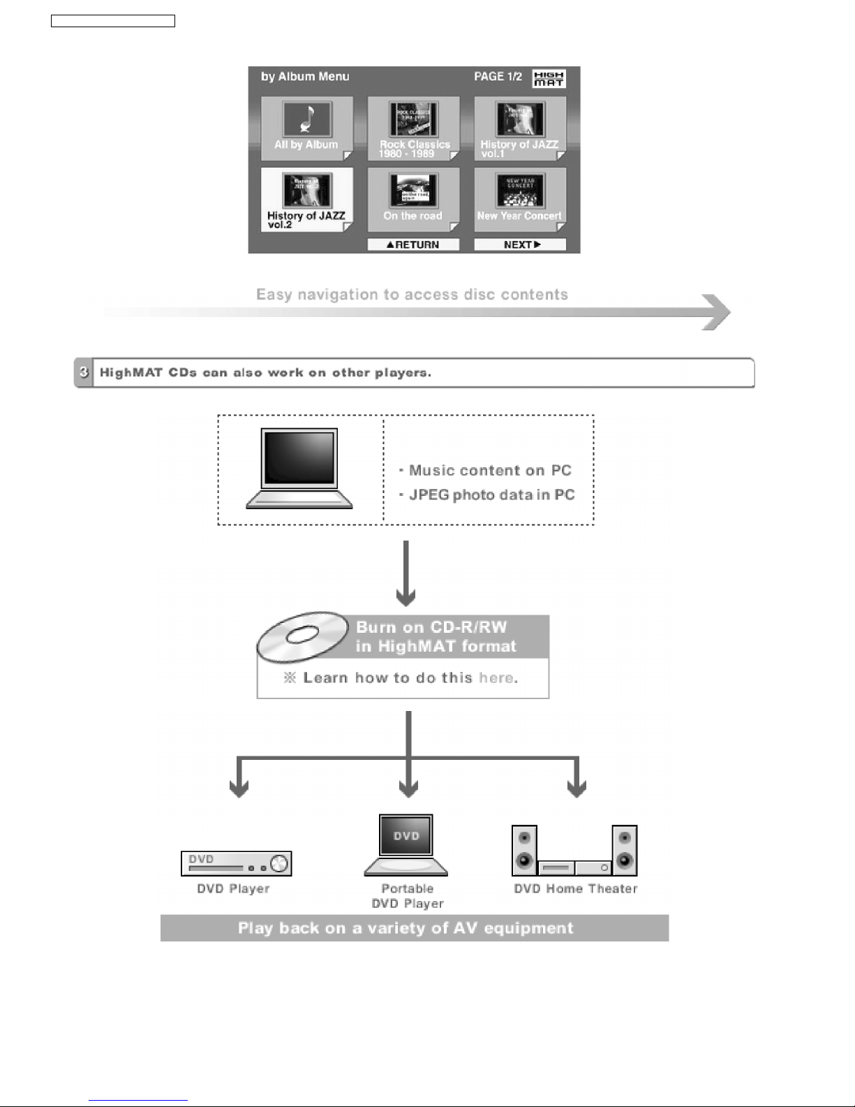
When you create your homemade CDs with software that supports HighMAT CD burning, and then play them back on a DVD
player that supports HighMAT, you get better, easier navigation. You get folders you can access with a single click of your DVD
player´s remote control. You can view important information about your music like full song names, artist titles, album names and
genre. And you can get faster startup on your home entertainment device.
To enjoy the benefits of HighMAT, all you need is software that supports HighMAT for CD burning of music or photos, as well as
a home entertainment device like a DVD player that supports HighMAT for playback. Always look for the HighMAT logo on your
software or home entertainment device to ensure it supports the HighMAT experience.
17
SA-HT885WGC / SA-HT885 WGS

Remote control
AM loop antenna
FM indoor antenna
Video Cable
Speaker cable
AC cord
AC cord (For GS area)
System cable
Speaker label
9 Accessories
18
SA-HT885WGC / SA-HT885 WGS
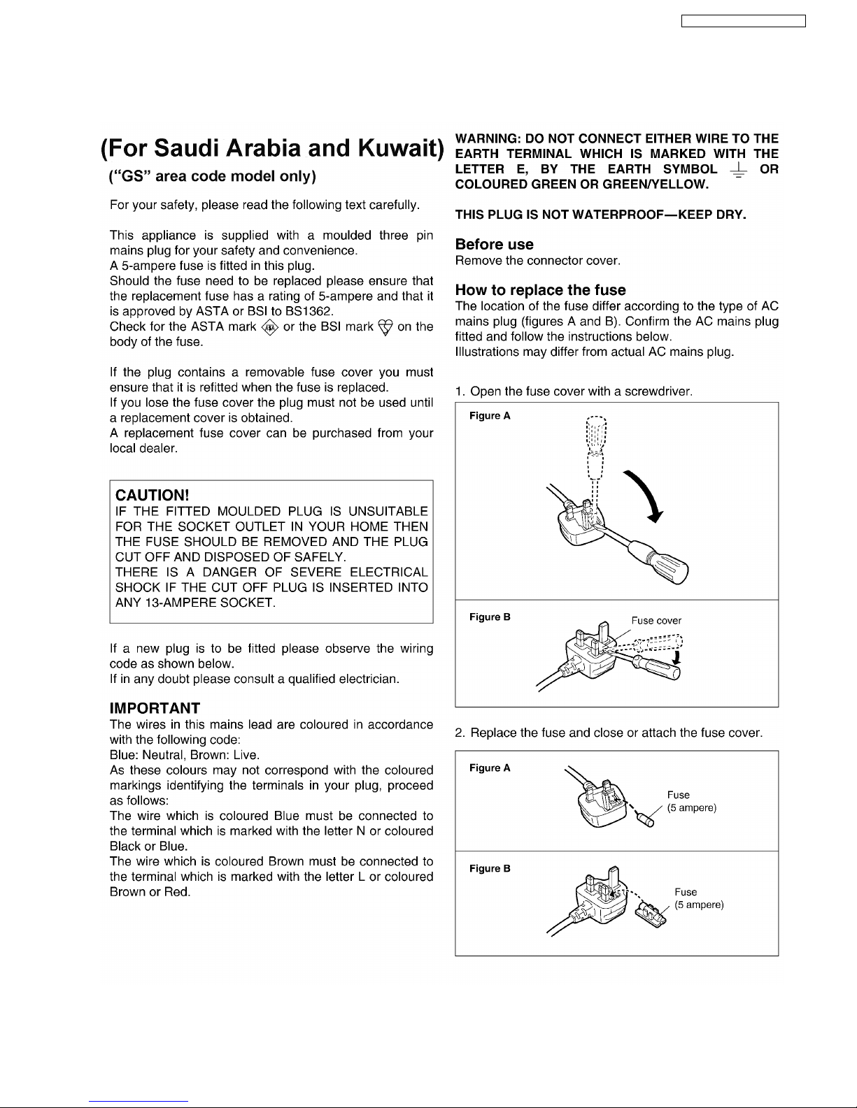
10 Caution for AC Cord
19
SA-HT885WGC / SA-HT885 WGS
11 Handling Precautions for Optical Pickup Unit
The laser diode in the optical pickup unit may break down due to static electricity of clothes or human body. Special care must be
taken avoid to electrostatic breakdown when servicing and handlin g the laser diode.
11.1. Cautions to Be Taken in Handling the Optical Pickup Unit
The laser diode in the optical pickup unit may be damaged due to electrostatic discharge generating from clothes or human body.
Special care must be taken avoid to electrostatic discharge damage when servicing the laser diode.
1. Do not give a considerable shock to the optical pickup unit as it has an extremely high-precise structure.
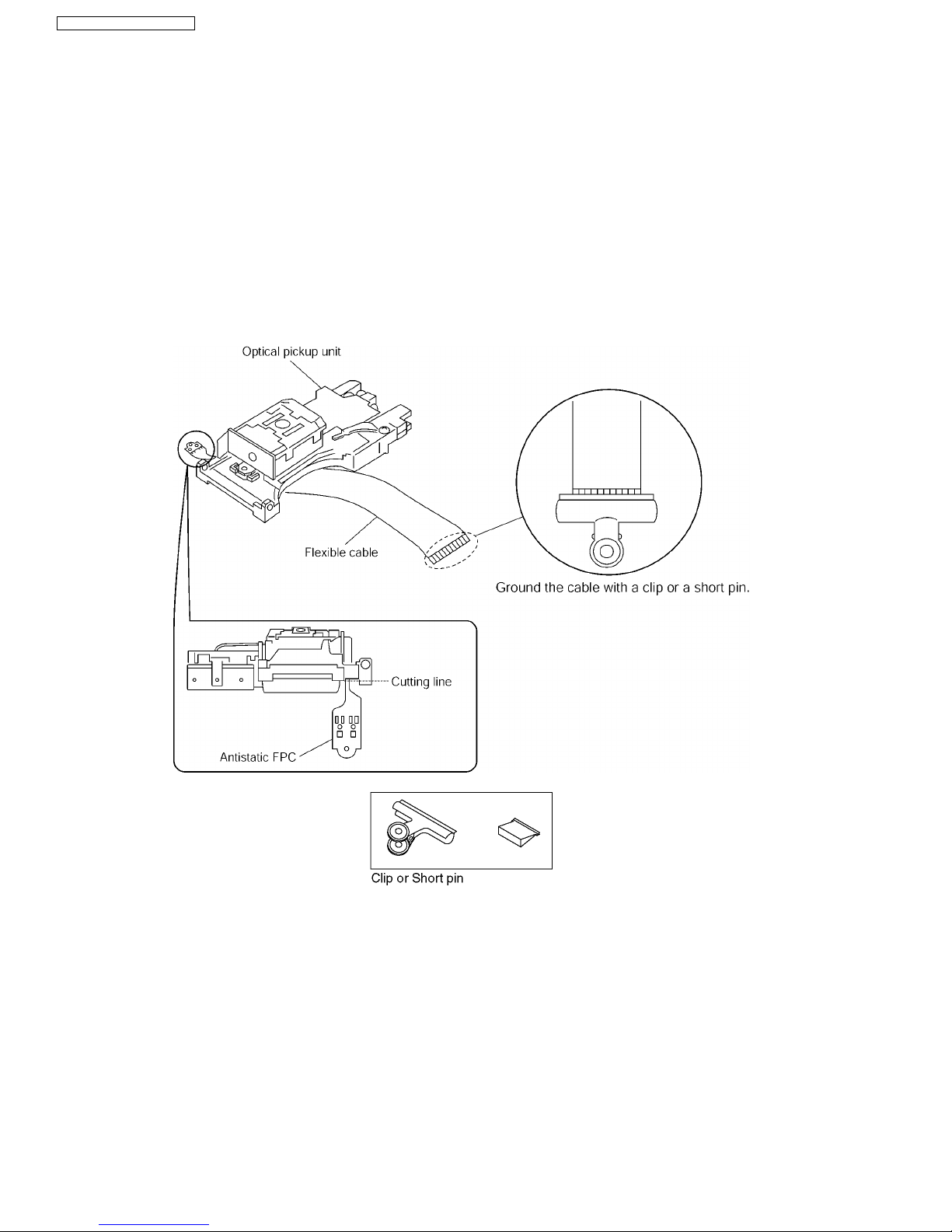
2. To prevent the laser diode from the electrostatic discharge damage, the flexible cable of the optical pickup unit removed should
be short-circuited with a short pin or a clip.
3. The flexible cable may be cut off if an excessive force is applied to it. Use with caution when handling the flexible cable.
4. The antistatic FPC is connec ted to the new optical pickup unit. After replacing the optical pickup unit and connecting the flexible
cable, cut off the antistatic FPC.
11.2. Cautions to Be Taken When Replacing the Optical Pickup
The flexible cable of the optical pickup unit which was supplied as a component is equipped with a short clip to prevent the laser
diode from being damaged due to electrostatic discharge. Remove the short clip before connecting the flexible cable and make
sure that the short land is open. (If the flexible cable is short-circuited, remove the solder.)
11.3. Grounding for electrostatic breakdown prevention
Some devices such as the DVD player use the optical pickup (laser diode) and the optical pickup will be damaged by static
electricity in the working environment. Proceed servicing works under the working environment where grounding works is
completed.
11.3.1. Worktable grounding
1. Put a conductive material (sheet) or iron sheet on the area where the optical pickup is placed, and ground the sheet.
20
SA-HT885WGC / SA-HT885 WGS

11.3.2. Human body grounding
1. Use the anti-static wrist strap to discharge the static electricity form your body.
21
SA-HT885WGC / SA-HT885 WGS
Some chassis components may have sharp edges.
Be carefu l when disassembling and servicing.
12 Disassembly and Main Component Replacement
Procedure
“ATTENTION SERVICER”
1. This section describes procedures for checking the operation of the major printed circuit boards and replacing the
main components.
2. For assembly after operation checks or replac ement, revers e the respective procedures.
Special reassembly procedures are described only when required.
3. Select items from the following index when checks or replacement are required.
· Disassembling the Top Cabinet
· Disassembling the Lid assembly (When taking out disc manually)
· Disassembling the Front Panel
· Disassembling the FL P.C.B., Volume P.C.B and MIC P.C.B.
· Disassembling the DVD mechanism Unit
· Disassembling the DVD Module P.C.B
· Disassembling the Rear panel
· Disassembling the Main.P .C.B.
12.1. Disassembly Procedure
22
SA-HT885WGC / SA-HT885 WGS
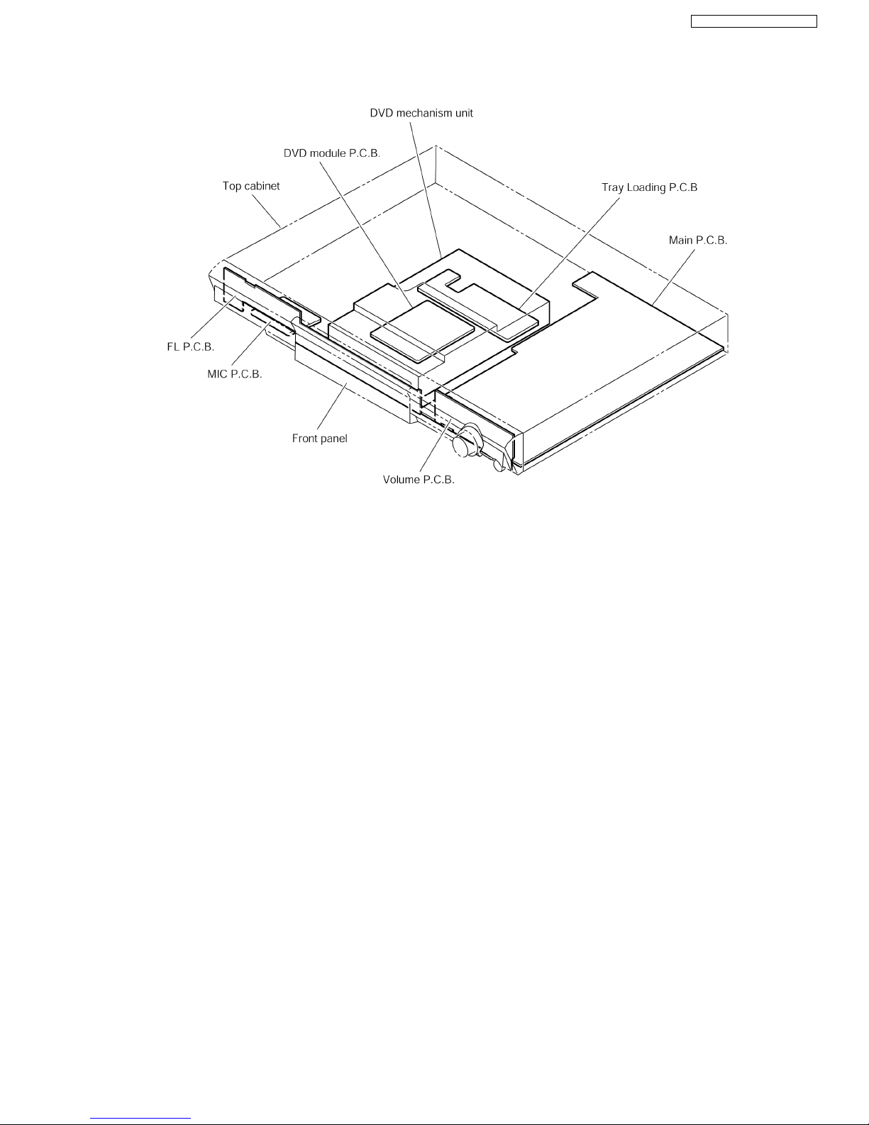
12.2. Main Components and P.C.B. Locations.
23
SA-HT885WGC / SA-HT885 WGS

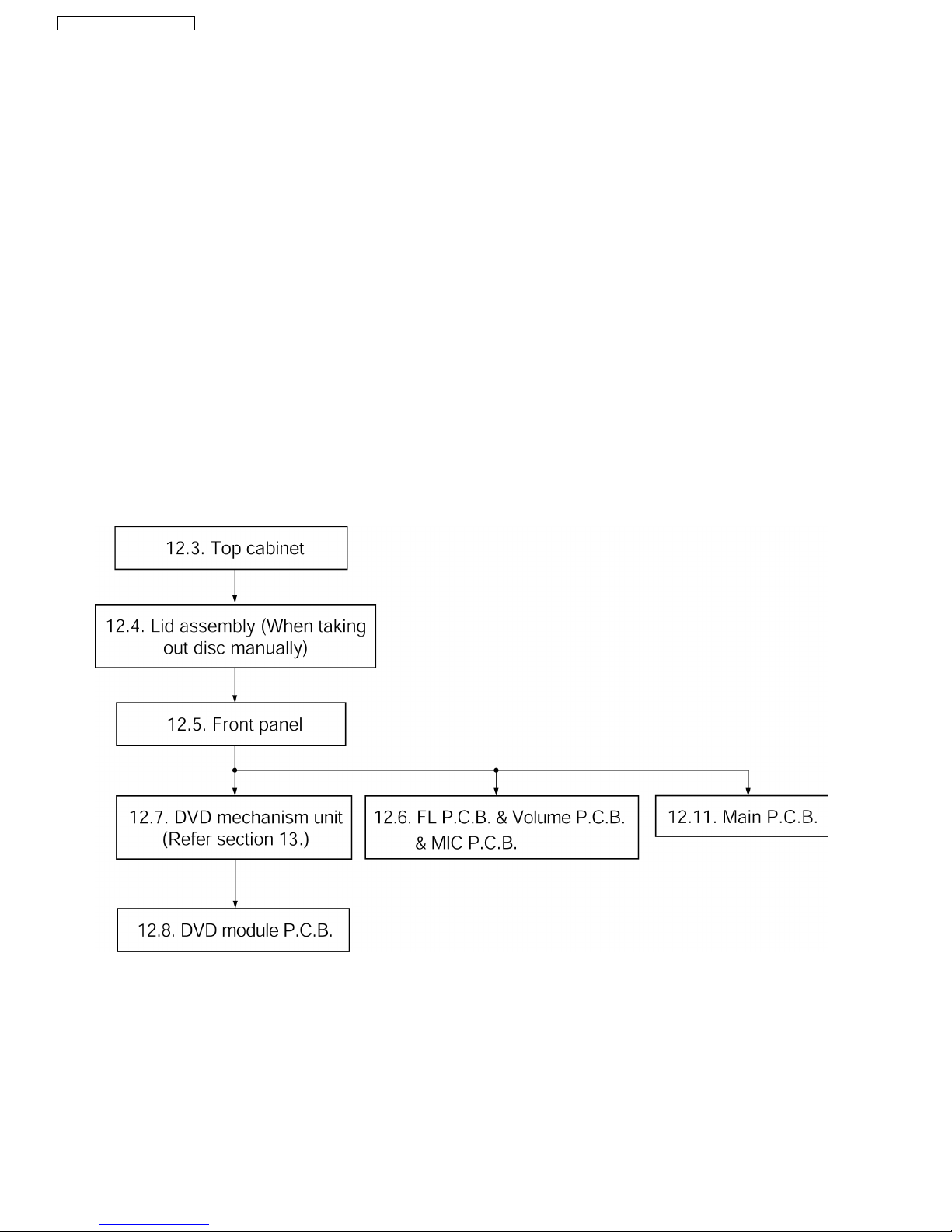
12.3. Disassembling the Top
Cabinet
Step 1 Unscrew the screw.
Step 2 Lift up and remove the top cabinet.
12.4. Disassembling the Lid
assembly (When taking out
disc manually)
· Follow the (Step 1) - (Step 2) of Item 12.3.
Step 1 Separates the gear for drawing out tray from the
mechanism unit. It inserts a screw driver in the gear. (The gear
jig)
Step 2 Insert the gear jig into the tray open/ close hole.
Step 3 Turn the gear jig counterclockwise to open the tray.
Note : Do not use force to push the tray backwards as it can
damage the mecha nism unit.
Turn the gear jig clockwise to return tray.
24
SA-HT885WGC / SA-HT885 WGS
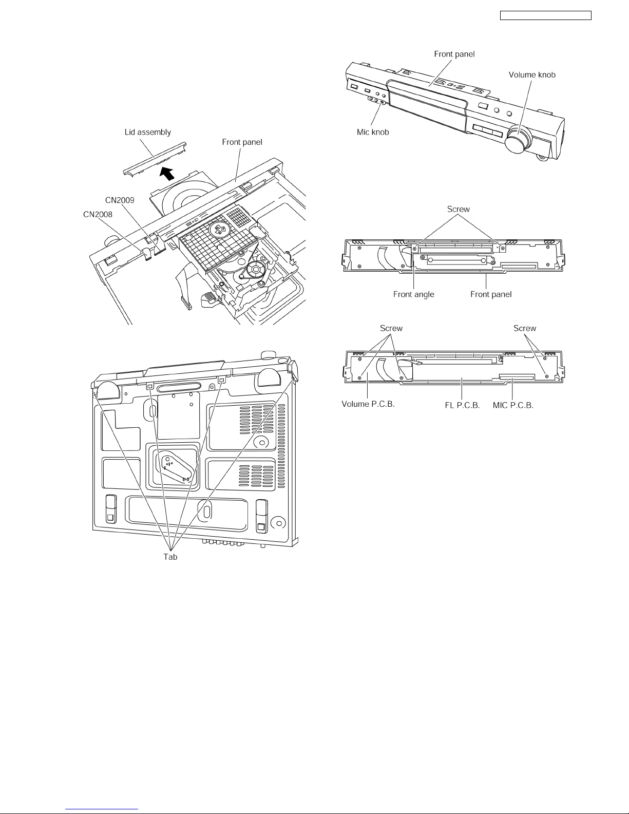
12.5. Disassembling the Front Panel
· Follow the (Step 1) - (Step 2) of Item 12.3.
· Follow the (Step 1) - (Step 3) of Item 12.4.
Step 1 Remove the lid assembly from the tray section.
Step 2 Detach FFC cables at connectors. (CN2008, CN2009)
Step 3 Release the tabs.
Step 4 Lift up the front panel to remove it.
12.6. Disassembling the FL P.C.B.,
Volume P.C.B. and MIC P.C.B.
· Follow the (Step 1) - (Step 2) of Item 12.3.
· Follow the (Step 1) - (Step 3) of Item 12.4.
· Follow the (Step 1) - (Step 4) of Item 12.5.
Step 1 Remove the volume knob and mic knob.
Step 2 Unscrew the screws.
Step 3 Remove the front angle.
Step 4 Unscrew the screws.
12.7. Disassembling the DVD
mechanism Unit
· Follow the (Step 1) - (Step 2) of Item 12.3.
· Follow the (Step 1) - (Step 3) of Item 12.4.
· Follow the (Step 1) - (Step 4) of Item 12.5.
Step 1 Turn the gear jig clockwise to close the tray.
Step 2 Unscrew the screws.
Step 3 Detach FFC cable at connectors. (CN2004, H2000).
Step 4 Lift up the mechanism unit vertically.
25
SA-HT885WGC / SA-HT885 WGS
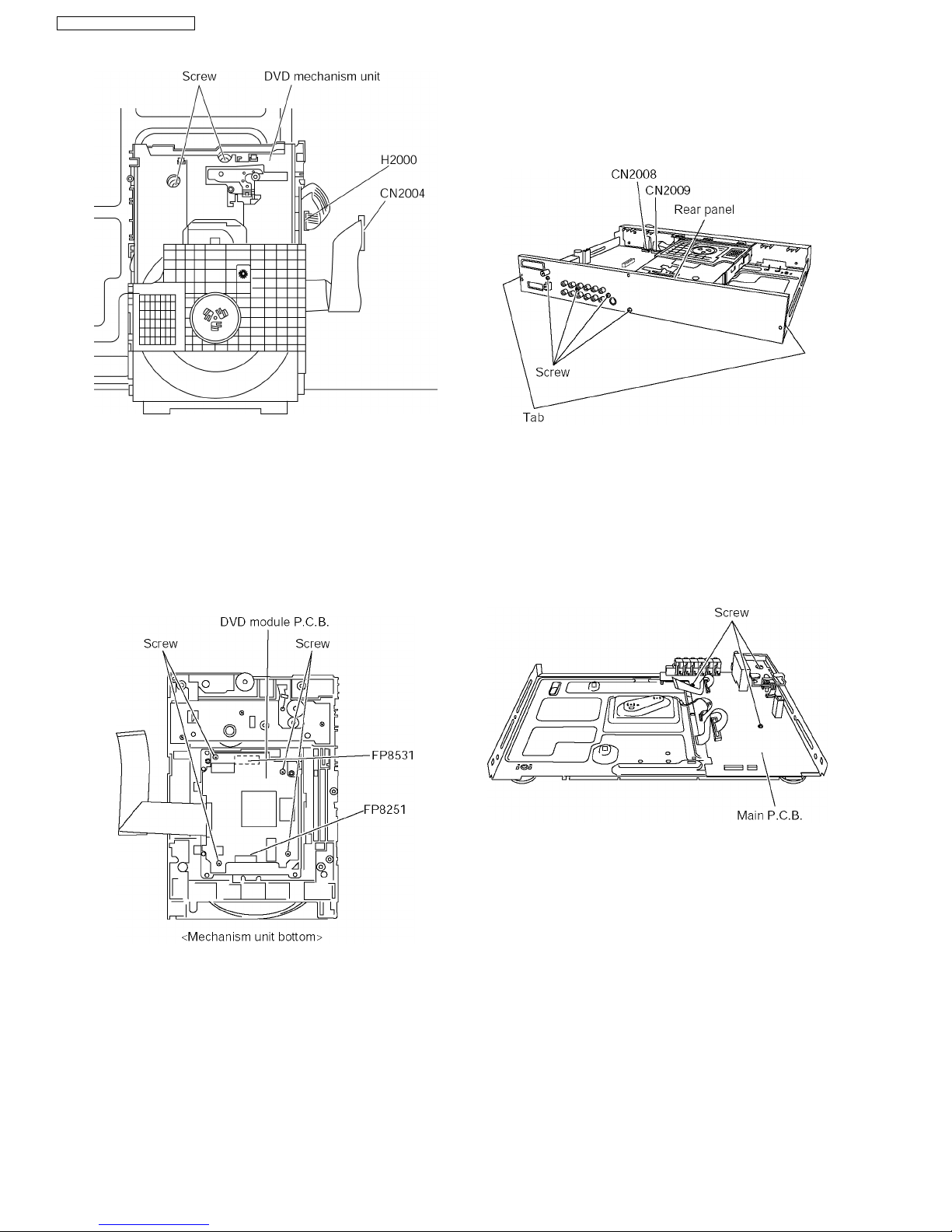
12.8. Disassembling the DVD
Module P.C.B.
· Follow the (Step 1) - (Step 2) of Item 12.3.
· Follow the (Step 1) - (Step 3) of Item 12.4.
· Follow the (Step 1) - (Step 4) of Item 12.5.
· Follow the (Step 1) - (Step 4) of Item 12.7.
Step 1 Unscrew the screws.
Step 2 Detach FFC cable at the connectors.(FP8201, FP8501)
12.9. Disassembling the Rear panel
· Follow the (Step 1) - (Step 2) of Item 12.3.
Step 1 Unscrew the screws.
Step 2 Release the tabs.
12.10. Disassembling Main P.C.B.
· Follow the (Step 1) - (Step 2) of Item 12.3.
· Follow the (Step 1) - (Step 3) of Item 12.4.
· Follow the (Step 1) - (Step 4) of Item 12.5.
· Follow the (Step 1) - (Step 4) of Item 12.7.
· Follow the (Step 1) - (Step 2) of Item 12.9.
Step 1 Unscrew the screws.
26
SA-HT885WGC / SA-HT885 WGS
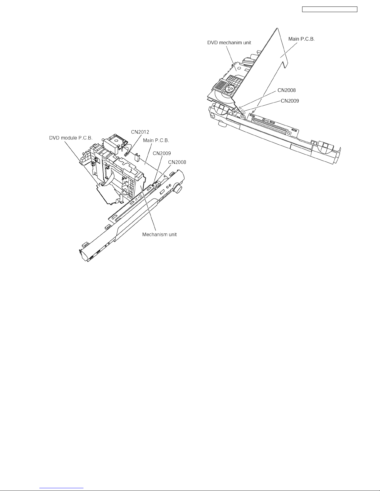
12.11. Service Position
12.11.1. Servicing position of the DVD
Module P.C.B.
· Follow the (Step 1) - (Step 2) of Item 12.3.
· Follow the (Step 1) - (Step 3) of Item 12.4.
· Follow the (Step 1) - (Step 4) of Item 12.5.
· Follow the (Step 1) - (Step 4) of Item 12.7.
· Follow the (Step 1) of Item 12.8.
· Follow the (Step 1) - (Step 2) of Item 12.9.
Step 1 Connect FFC cable at connector. (CN2008, CN2009)
Step 2 Turn Mechanism unit to vertically position.
12.11.2. Servicing position of the Main
P.C.B.
· Follow the (Step 1) - (Step 2) of Item 12.3.
· Follow the (Step 1) - (Step 3) of Item 12.4.
· Follow the (Step 1) - (Step 4) of Item 12.5.
· Follow the (Step 1) - (Step 4) of Item 12.7.
· Follow the (Step 1) of Item 12.8.
· Follow the (Step 1) - (Step 2) of Item 12.9.
Step 1 Connect FFC cable at connector. (CN2008, CN2009)
Step 2 Turn Main P.C.B to vertically position.
27
SA-HT885WGC / SA-HT885 WGS
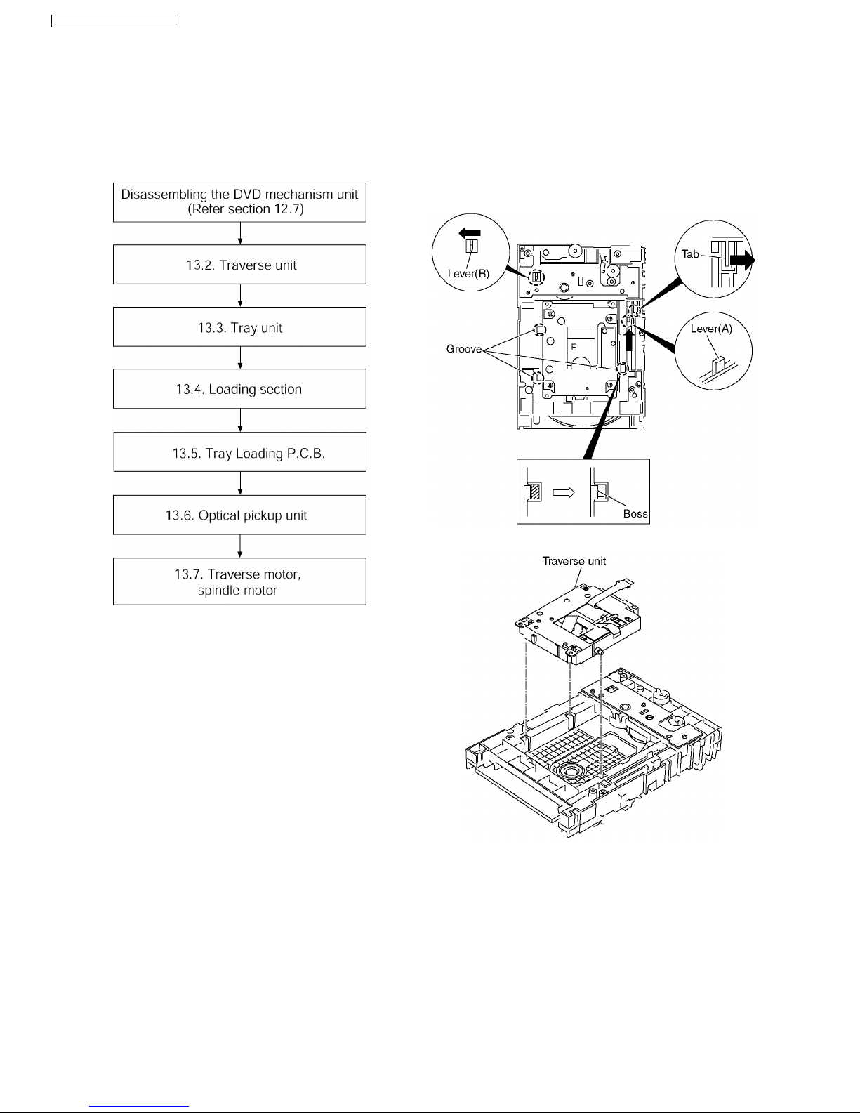
13 Assembling and
disassembling the DVD
mechanism Unit
13.1. Disassembly Procedure
13.2. Traverse Unit
1. Slide the lever (A) in the arrow direction (to the opposite
side) till it stops.
2. Slide the lever (A) further by bending the tab at the right
side of the lever A in the right direction. (The right groove
opens and the boss becomes seen.)
3. Open the lever (B) to left. (The 2 grooves at the left side
open.)
4. Remove the traverse unit
28
SA-HT885WGC / SA-HT885 WGS
 Loading...