

Panasonic SA-HT870E, SA-HT870EG, SA-HT870EB Service Manual
lGeneral
Power Source:
For (E, EG) areas:
A
C 230 V, 50 Hz
For (EB) area:
A
C 230-240 V, 50 Hz
Power consumption: 25 W
Dimensions (W×H×D): 430×68×359.2 mm
Mass: 3.2 kg
lAmplifier section
RMS Output Power: Dolby Digital Mode
lTotal RMS Dolby Digital
mode Power:
1000 W
At 1kHz and total harmonic of 10%
lFront: 170 W/ Channel (6Ω)
lCenter: 260 W/ Channel (4Ω)
lSurround: 70 W/ Channel (4Ω)
At 100Hz and total harmonic of 10%
lActive subwoofers: 260 W/ Channel (4Ω)
DIN Output Power: Dolby Digital Mode:
lTotal DIN Dolby Digital mode Power:
750 W
At 1kHz and total harmonic of 1%
lFront: 140 W/ Channel (6Ω)
lCenter: 180 W/ Channel (4Ω)
lSurround: 55 W/ Channel (4Ω)
© 2004 Panasonic AVC Networks Singapore Pte.
Ltd. All rights reserved. Unauthorized copying and
distribution is a violation of law.
SA-HT870E
SA-HT870EB
SA-HT870EG
Colour
(S).......................Silver Type
At 100Hz and total harmonic of 1%
lSubwoofer: 180 W/ Channel (4Ω)
lFM tuner section
Frequency Range: 87.5-108.0MHz
(50kHz in step)
Sensitivity: 2µV (IHF)
S/N 26dB 2µV
Antenna Terminal: 75Ω (non balance)
lAM tuner section (AM/MW)
Frequency Range:
522-1629kHz (9kHz in step)
520-1630kHz (10kHz in step)
AM Sensitivity S/N 20dB at
999kHz:
560µV/m
Phone Jack:
Terminal: Stereo 3.5mm jack
lDisc section
Discs played [8 cm or 12 cm]:
(1) DVD-RAM (DVD-VR compatible, JPEG formatted discs)
(2) DVD-Audio
(3) DVD-Video
(4) DVD-R (DVD-Video compatible)
(5) CD-Audio (CD-DA)
(6) Video CD
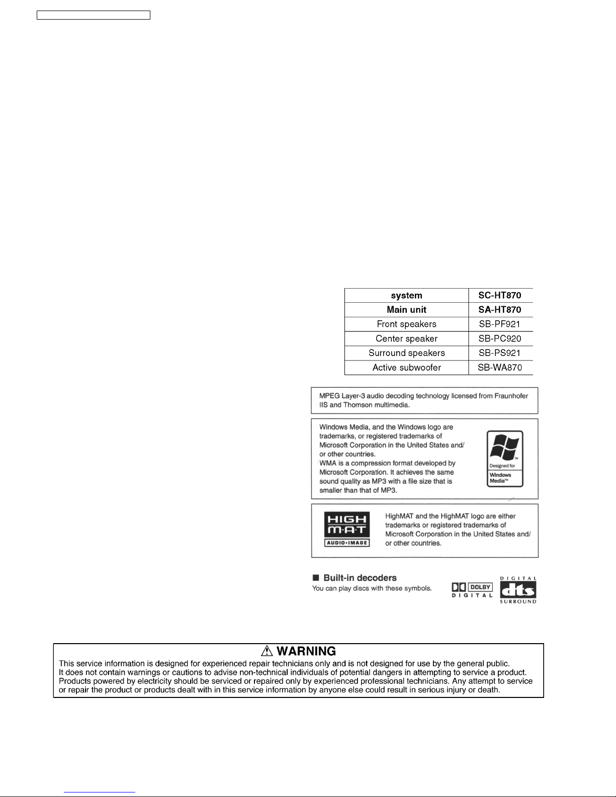
DVD Home Theater Sound System
Specifications
ORDER NO.MD0403138C2
(7) SVCD (Conforming to IEC62107)
(8) CD-R/CD-RW (CD-DA, Video-CD, SVCD, MP3, WMA, JPEG
formatted discs)
(9) MP3/WMA
lMaximum number of recognizable audio and picture contents
and groups:
4000 audio and picture
contents and 400 groups
lCompatible compression rate:
MP3: between 32 kbps and 320 kbps
WMA: between 48 kbps and 320 kbps
(10) JPEG
lExif Ver 2.1 JPEG Baseline files
lPicture resolution: between 320 x 240 and 6144 x 4096
pixels (sub sampling is 4:2:2 or 4:2:0)
(11) HighMAT Level 2 (Audio and lmage)
Pick up:
Source of light beam:
Semiconductor Laser
Wavelength:
lCD: 785nm
lDVD: 662nm
Audio output (DISC):
Number of channels:
5.1 ch (FL, FR, C, SL, SR,
SW)
Audio performance (measured at LINE OUT terminal):
Frequency response:
DVD (linear audio): 4 Hz-22 kHz (48 kHz sampling)
4 Hz-44 kHz (96 kHz sampling)
DVD-Audio:
4 Hz-88 kHz (192 kHz
sampling)
CD-Audio: 4 Hz-20 kHz
S/N ratio:
CD-Audio:
95 dB
Dynamic range:
DVD (linear audio): 95 dB
CD-Audio: 93 dB
Total harmonic distortion:
CD-Audio: 0.005 %
lVideo section
V
ideo system:
Signal system: PAL 625/50, PAL 525/60,
NTSC
Composite video output:
Output level:
1 Vp-p (75 Ω)
Terminal: Pin jack (1 system)
S-video output:
Y
output level: 1 Vp-p (75 Ω)
C output level: PAL; 0.3Vp-p (75 Ω)
NTSC; 0.286 Vp-p (75 Ω)
Terminal S terminal (1 system)
Component video output (480P/480I):
Y
output level: 1 Vp-p (75 Ω)
PBoutput level: 0.7 Vp-p (75 Ω)
PRoutput level: 0.7 Vp-p (75 Ω)
Terminal: Pin jack (Y: green, PB: blue,
P
R
: red) (1 system)
Power consumption in standby mode:
approx 0.7W
Note:
1. Specifications are subject to change without notice.
Mass and dimensions are approximate.
2. Total harmonic distortion is measured by the digital spectrum
analyzer.
Solder:
This model uses lead free solder (PbF).
2
SA-HT870E / SA-HT870EB / SA-HT870EG

1 Use of Active Subwoofer 4
1.1. Checking Player when Active Subwoofer is not used
4
2 Safety Precautions
5
2.1. GENERAL GUIDELINES
5
3 Prevention of Electro Static Discharge (ESD) to
Electrostatically Sensitive (ES) Devices
5
4 Before Repair and Adjustment (Using Active Subwoofer)
6
5 Protection Circuitry
6
6 Precaution of Laser Diode
7
7 About Lead Free Solder (PbF)
7
8 General Description
8
8.1. Operating instructions
8
8.2. Disc information
9
9 Accessories
10
10 Caution for AC Main Lead
11
11 Handling Precautions for Optical Pickup Unit
12
11.1. Cautions to Be Taken in Handling the Optical Pickup Unit
12
11.2. Cautions to Be Taken When Replacing the Optical Pickup
12
11.3. Grounding for electrostatic breakdown prevention
12
12 DISASSEM BLING THE CASING AND CHECKING P.C.B.S
14
12.1. Disassembly Procedure
14
12.2. Casing Parts and P.C.B. Positions
14
12.3. Top Cabinet
15
12.4. Tray (When taking out disc manually)
15
12.5. Front Panel
15
12.6. FL P.C.B. and Volume P.C.B.
16
12.7. Mechanism Unit
16
12.8. DVD Module P.C.B.
16
12.9. Rear panel
17
12.10. Main P.C.B.
17
12.11. Service Position
17
13 ASSEMBL ING AND DISASSEM BLING THE MECHANIS M UNIT
18
13.1. Disassembly Procedure
18
13.2. Traverse Unit
18
13.3. Tray
19
13.4. Loading section
20
13.5. Tray Loading P.C.B.
21
13.6. Optical Pickup Unit
22
13.7. Traverse Motor and Spindle Motor
25
14 DVD-Optic al Pick-up Self-Diagnosis and Replacement
Procedure
27
14.1. Optical Pickup Breakdown Diagnosis
27
14.2. Service Mode Table 1
28
14.3. DVD Self Diagnostic Function-Error Code
28
14.4. Last Error Code saved during NO PLAY
29
14.5. Service mode table 2
30
14.6. Sales demonstration lock function
32
14.7. Handling After Completing Repairs
32
15 Self-Diagn osis Function
33
15.1. Automatic Displayed Error Codes
33
15.2. Memorized Error Codes
33
16 Service Precautions
34
16.1. Recovery after the DVD player is repaired
34
16.2. Firmware version-up of the DVD player
34
17 Adjustmen t Procedure
35
17.1. Service Tools and Equipment
35
17.2. Important points in adjustment
35
17.3. Storing and Handling Test Discs
35
17.4. Optical adjustment
36
18 Abbreviations
37
19 Voltage Chart
39
19.1. DVD Module P.C.B.
39
19.2. Main P.C.B.
41
19.3. Tray Loading P.C.B.
43
19.4. Scart P.C.B.
43
19.5. FL P.C.B.
43
20 Schematic Diagram Notes
44
21 Block Diagram
45
22 Schematic Diagram
51
23 Printed Circuit Board Diagram
59
24 Wiring Connection Diagram
63
25 Illustration of IC 痴, Transistors and Diodes
65
26 Terminal Function of ICs
66
26.1. IC2018 (C2CBHG000139): System control
66
27 Parts Location and Replacement Parts List
67
27.1. Loading Mechanism, Traverse Unit & Cabinet
68
27.2. Component Parts List
71
27.3. Packing Materials & Accessories Parts List
80
27.4. Packaging
81
CONTENTS
Page Page
3
SA-HT870E / SA-HT870EB / SA-HT870EG
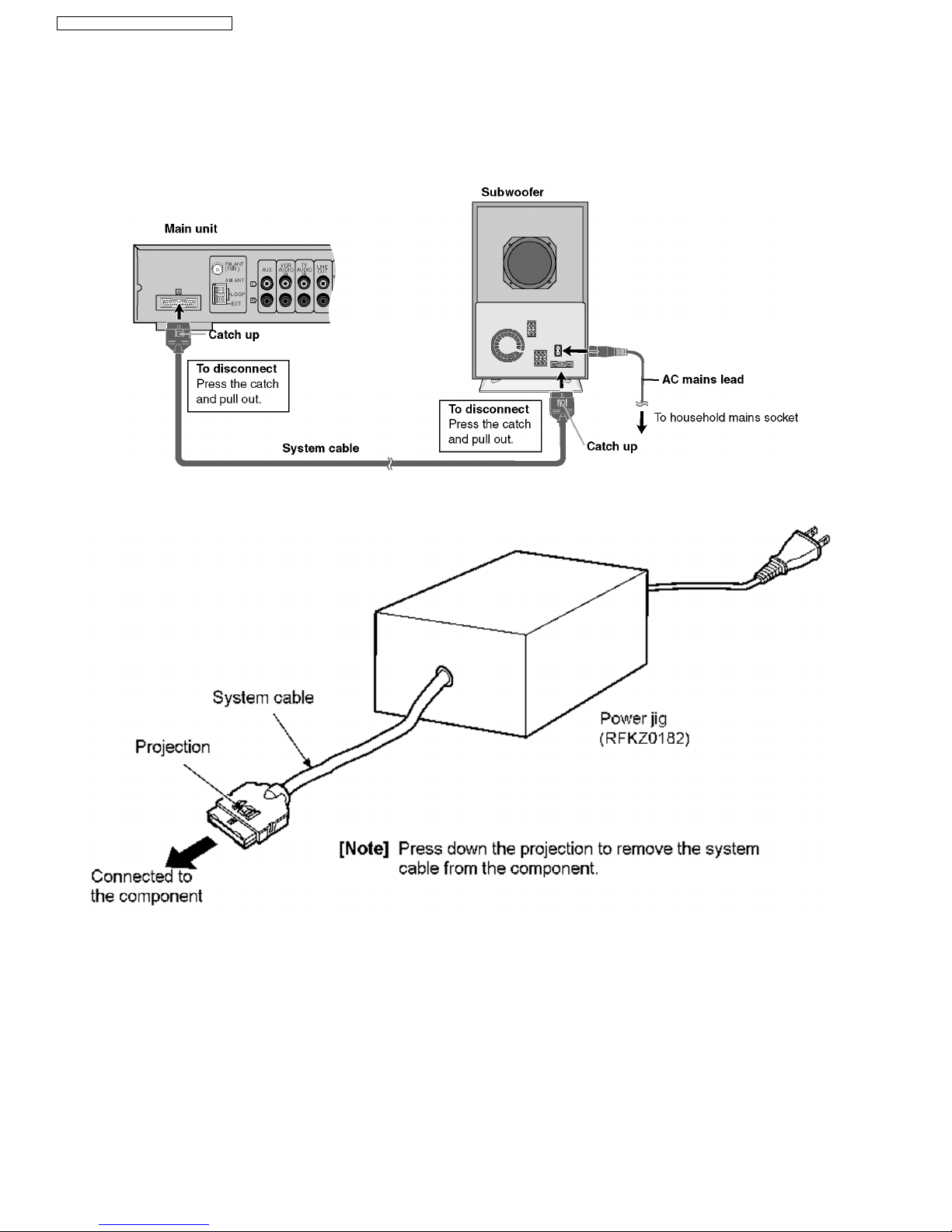
1 Use of Active Subwoofer
1.1. Checking Player when Active Subwoofer is not used
1. This unit uses the active subwoofer to supply the power of the component, and the active subwoofer should be connected to
the component to check operational conditions of the component.
2. If the active subwoofer is not available due to repair of the unit, use the following equipment.
Jig product number: RFKZ0182 (110V, 127V, 220V, 230V-240V for overseas domestic use)
4
SA-HT870E / SA-HT870EB / SA-HT870EG
2.1.1. LEAKAGE CURRENT COLD
CHECK
1. Unplug the AC cord and connect a jumper between the two
prongs on the plug.
2. Measure the resistance value, with an ohmmeter, between
the jumpered AC plug and each exposed metallic cabinet
part on the equipment such as screwheads, connectors,
control shafts, etc. When the exposed metallic part has a
return path to thechassis, the reading should be between
1MΩand 5.2MΩ.
When the exposed metal does not have a return path to
the chassis, the reading must be
.
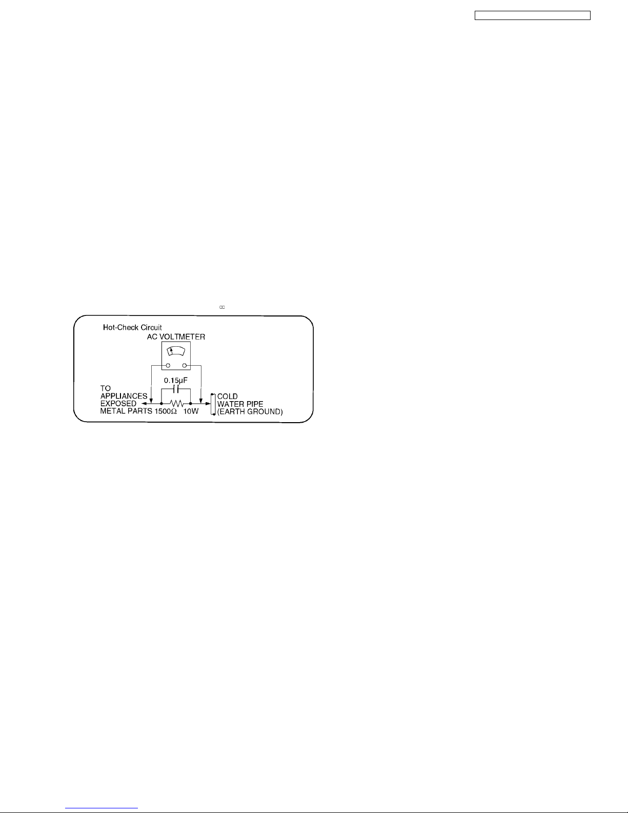
Figure 1
2.1.2. LEAKAGE CURRENT HOT CHECK
(See Figure 1 .)
1. Plug the AC cord directly into the AC outlet. Do not use an
isolation transformer for this check.
2. Connect a 1.5kΩ, 10 watts resistor, in parallel with a 0.15µF
capacitors, between each exposed metallic part on the set
and a good earth ground such as a water pipe, as shown in
Figure 1 .
3. Use an AC voltmeter, with 1000 ohms/volt or more
sensitivity, to measure the potential across the resistor.
4. Check each exposed metallic part, and measure the
voltage at each point.
5. Reverse the ACplug in the AC outletand repeat each of the
above measurements.
6. The potential at any point should not exceed 0.75 volts
RMS. A leakage current tester (Simpson Model 229 or
equivalent) may be used to make the hot checks, leakage
current must not exceed 1/2 milliamp. In case a
measurement is outsideof the limits specified, there is a
possibility of a shock hazard, and the equipment should be
repaired and rechecked before it is returned to the
customer.
2 Safety Precautions
2.1. GENERAL GUIDELINES
1. When servicing, observe the original lead dress. If a short circuit is found, replace all parts which have been overheated or
damaged by the short circuit.
2. After servicing, see to it that all the protective devices such as insulation barriers, insulation papers shields are properly
installed.
3. After servicing, make the following leakage current checks to prevent the customer from being exposed to shock hazards.
3 Prevention of Electro Static Discharge (ESD) to
Electrostatically Sensitive (ES) Devices
Some semiconductor (solid state) devices can be damaged easily by static electricity. Such components commonly are called
Electrostatically Sensitive (ES) Devices. Examples of typical ES devices are integrated circuits and some field-effect transistorsand
semiconductor
"chip" components. The following techniques should be used to help reduce the incidence of component damage
caused by electro static discharge (ESD).
1. Immediately before handling any semiconductor component or semiconductor-equipped assembly, drain off any ESD on your
body by touching a known earth ground. Alternatively, obtain and wear a commercially available dischargingESD wrist strap,
which should be removed for potential shock reasons prior to applying power to the unit under test.
2. After removing an electrical assembly equipped with ES devices, place the assembly on a conductive surface such as
aluminum foil, to prevent electrostatic charge buildup or exposure of the assembly.
3. Use only a grounded-tip soldering iron to solder or unsolder ES devices.
4. Use only an anti-static solder removal device. Some solder removal devices not classified as "anti-static (ESD protected)" can
generate electrical charge sufficient to damage ES devices.
5. Do not use freon-propelled chemicals. These can generate electrical charges sufficient to damage ES devices.
6. Do not remove a replacement ES device from its protective package until immediately before you are ready to install it. (Most
replacement ES devices are packaged with leads electrically shorted together by conductive foam, aluminum foil or
comparableconductive material).
7. Immediately before removing the protective material from the leads of a replacement ES device, touch the protective material
to the chassis or circuit assembly into which the device will be installed.
5
SA-HT870E / SA-HT870EB / SA-HT870EG
Caution
Be sure no power is applied to the chassis or circuit, and observe all other safety precautions.
8. Minimize bodily motions when handling unpackaged replacement ES devices. (Otherwise harmless motion such as the
brushing together of your clothes fabric or the lifting of your foot from a carpeted floor can generate static electricity
(ESD)sufficient to damage an ES device).
4 Before Repair and Adjustment (Using Active Subwoofer)
Disconnect AC power, discharge Power Supply Capacitors C546~C549 through a 10 Ω, 10 W resistor to ground.
DO NOT SHORT-CIRCUIT DIRECTLY (with a screwdriver blade, for instance), as this may destroy solid state devices.
After repairs are completed, restore power gradually using a variac, to avoid overcurrent.
Current consumption at AC 230-240 V, 50 Hz in NO SIGNAL mode should be ~ 1000 mA.
5 Protection Circuitry
The protection circuitry may have operated if either of the following conditions are noticed:
· No sound is heard when the power is turned on.
· Sound stops during a performance.
The function of this circuitry is to prevent circuitry damage if, for example, the positive and negative speaker connection wires are
“shorted”, or if speaker systems with an impedance less than the indicated rated impedance of the amplifier are used.
If this occurs, follow the procedure outlines below:
1. Turn off the power.
2. Determine the cause of the problem and correct it.
3. Turn on the power once again after one minute.
Note:
When the protection circuitry functions, the unit will not operate unless the power is first turned off and then on again.
6
SA-HT870E / SA-HT870EB / SA-HT870EG
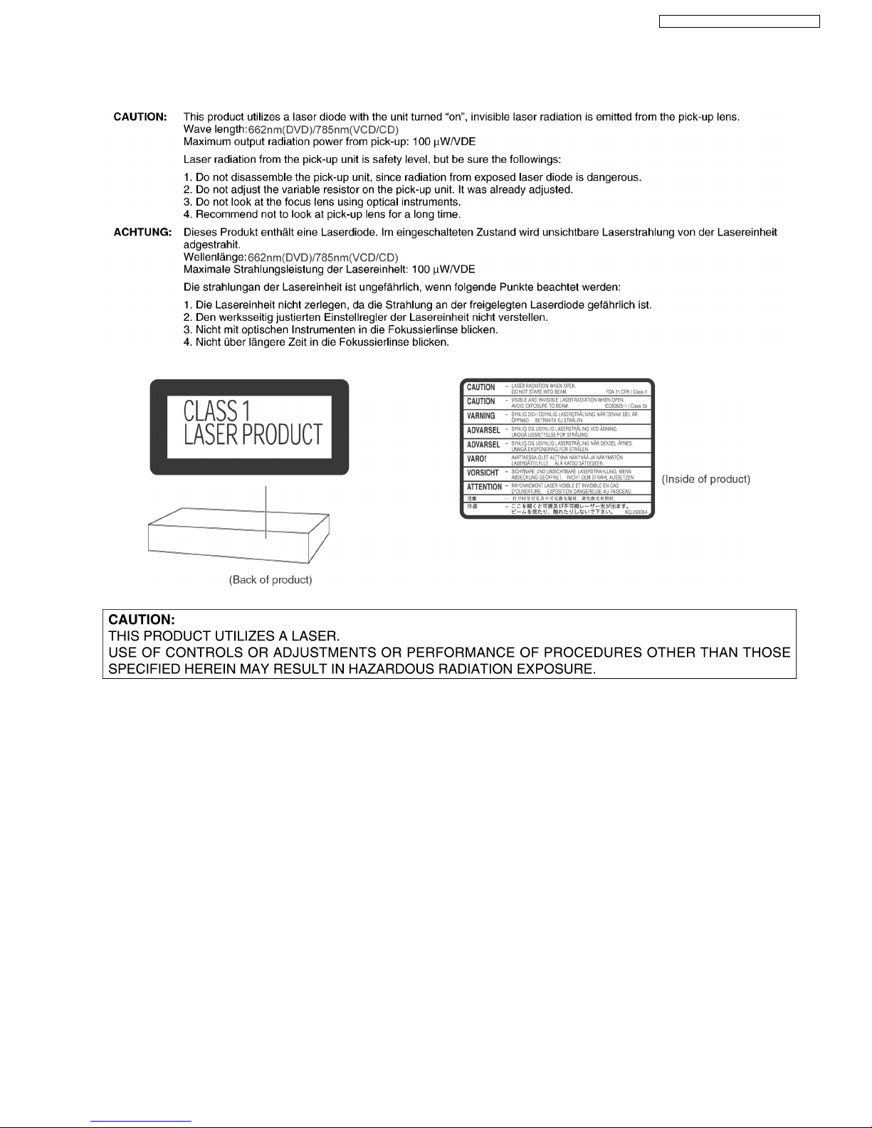
6 Precaution of Laser Diode
7 About Lead Free Solder (PbF)
Distinction of PbF PCB: PCBs (manufactured) using lead free solder will have a Pbf stamp on the PCB.
Caution:
· Pb free solder has a higher melting point than standard solder; Typically the melting point is 50 - 70°F (30 - 40°C) higher.
Please use a high temperature soldering iron. In case of the soldering iron with temperature control,please set it to 700 ±
20°F (370 ± 10°C).
· Pb free solder will tend to splash when heated too high (about 1100°F/ 600°C).
When soldering or unsoldering, please completely remove all of the solder on the pins or solder area, and be sure to heat the
soldering points with the Pb free solder until it melts enough.
7
SA-HT870E / SA-HT870EB / SA-HT870EG
8 General Description
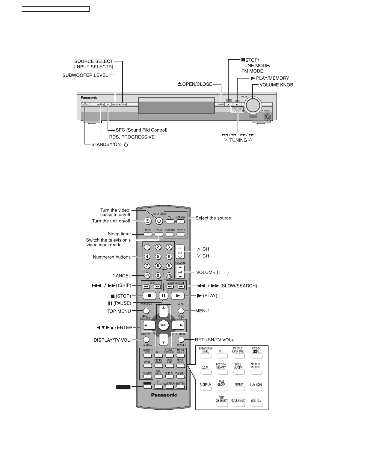
8.1. Operating instructions
SHIFTSHIFT
[ /I]
SHIFT
8
SA-HT870E / SA-HT870EB / SA-HT870EG
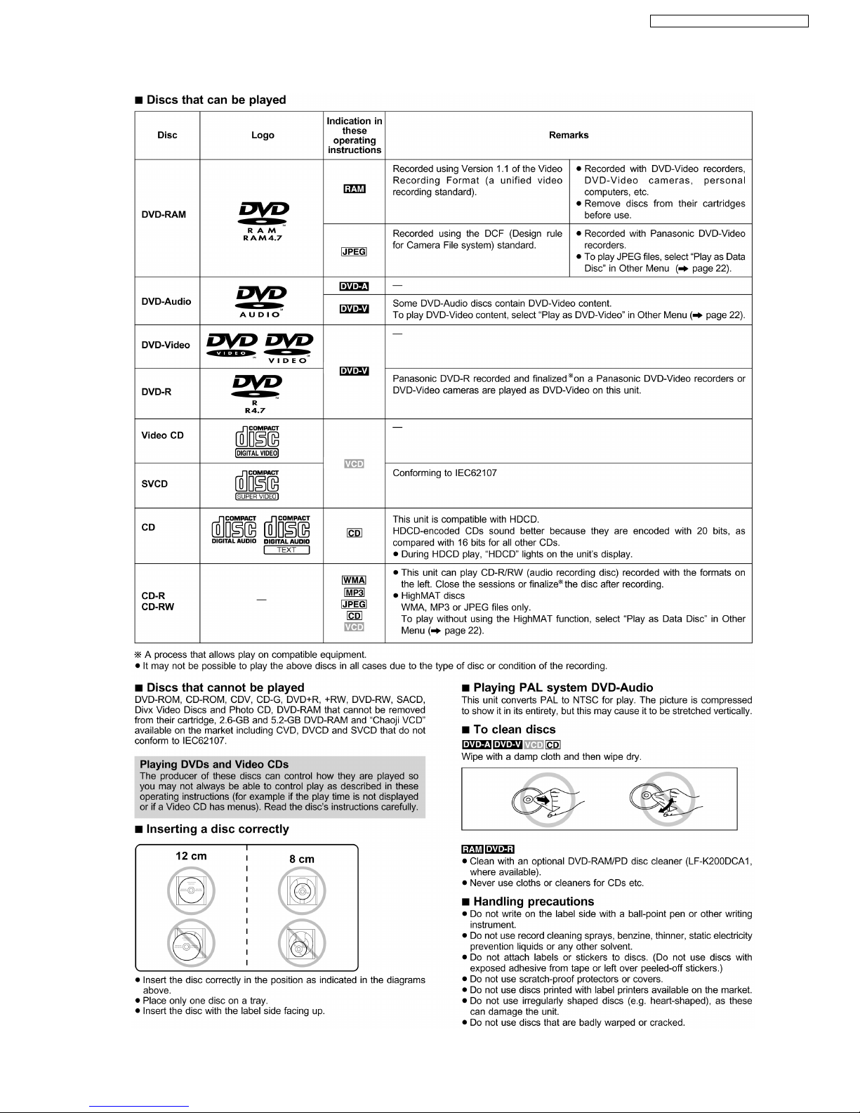
8.2. Disc information
9
SA-HT870E / SA-HT870EB / SA-HT870EG
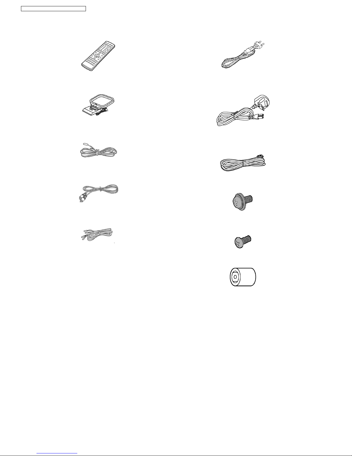
Remote control
AM loop antenna
FM indoor antenna
Video Cable
Speaker cable
(4m×1)
AC power supply cord
(For E, EG areas)
AC power supply cord
(For EB area)
System cable
Large washer
screw
Small screw
Antenna plug adaptor
(For EB area only)
9 Accessories
10
SA-HT870E / SA-HT870EB / SA-HT870EG
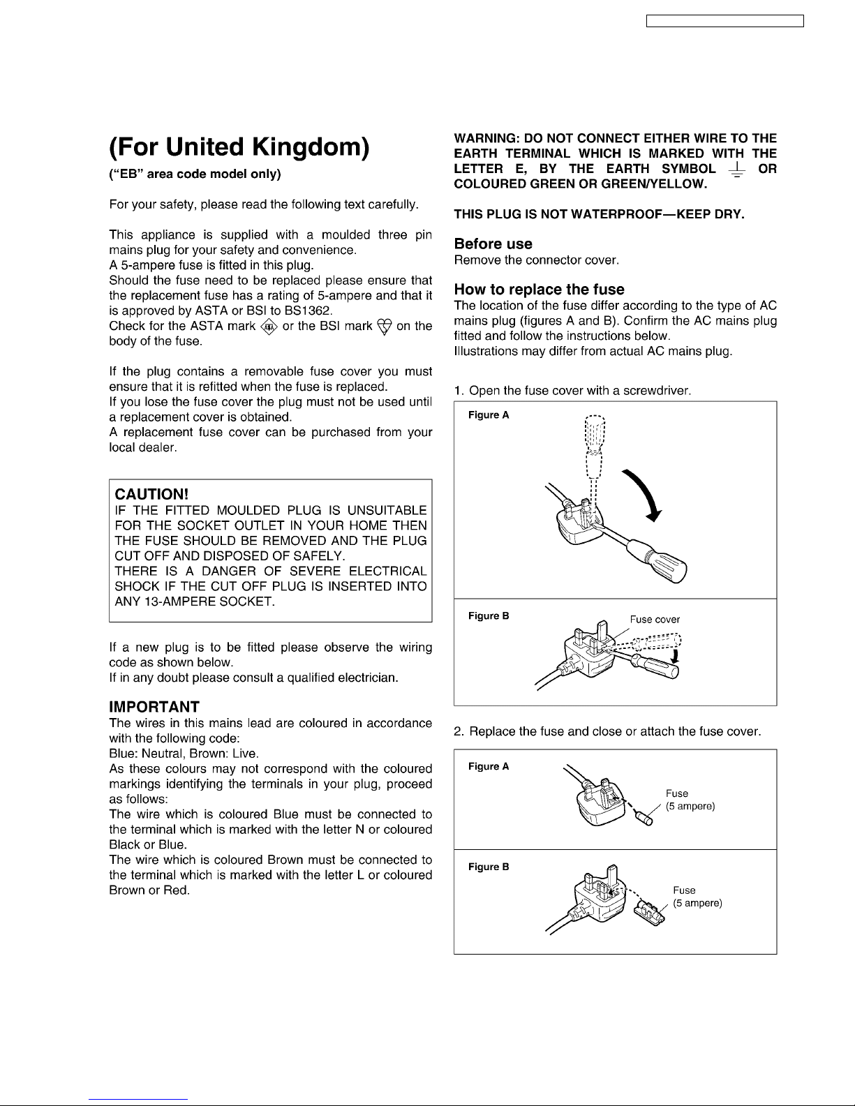
10 Caution for AC Main Lead
11
SA-HT870E / SA-HT870EB / SA-HT870EG
11 Handling Precautions for Optical Pickup Unit
The laser diode in the optical pickup unit may brake down due to static electricity of clothes or human body. Use due caution to
electrostatic breakdown when servicing and handling the laser diode.
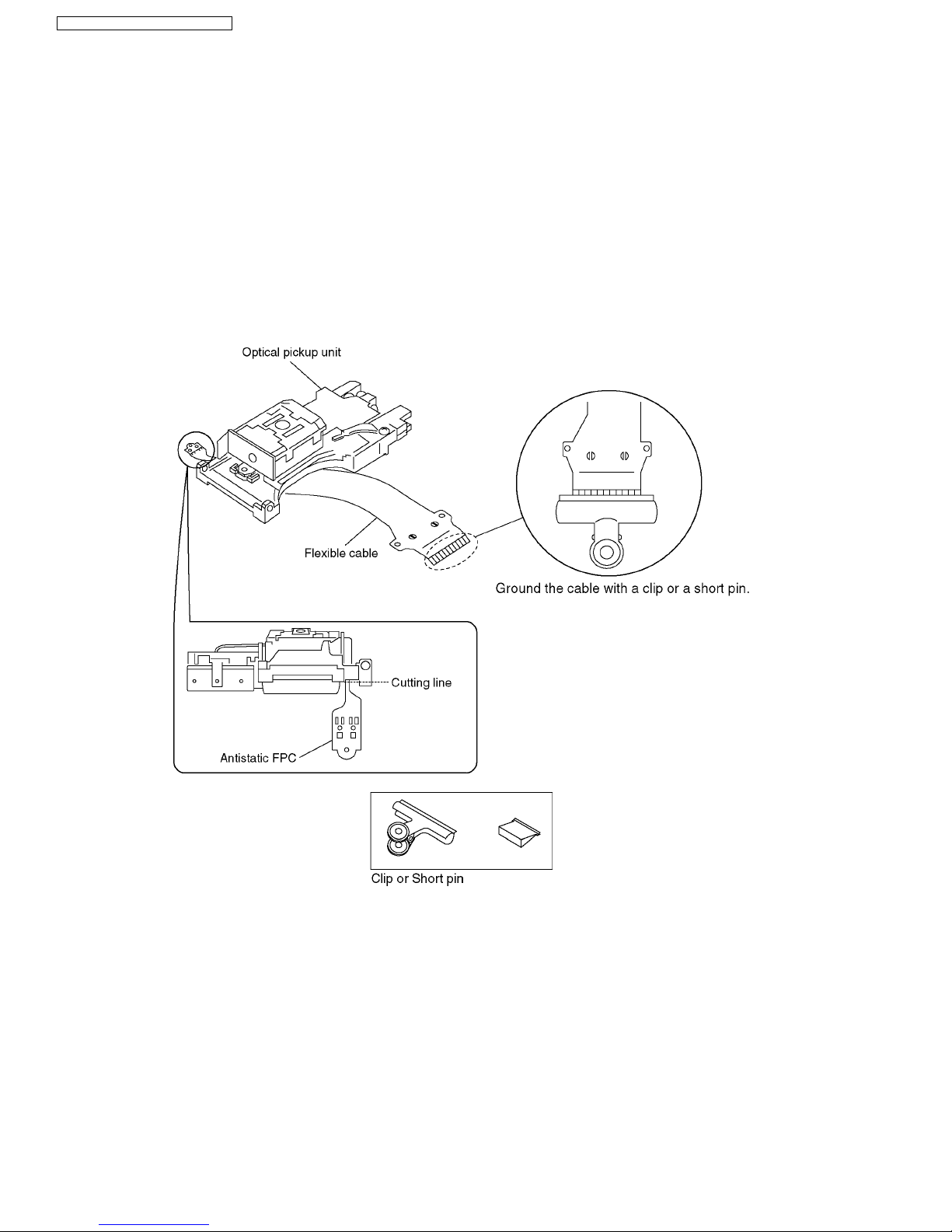
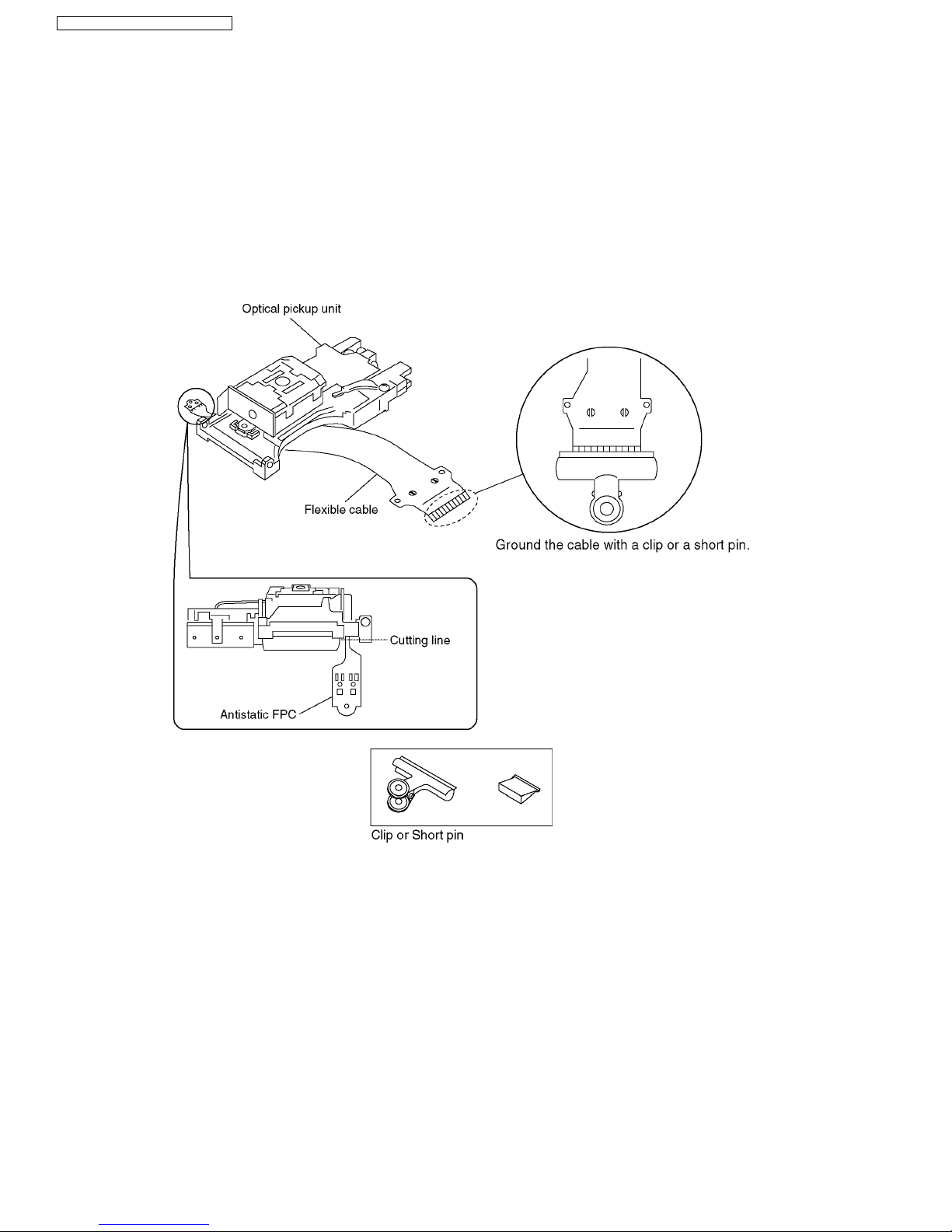
11.1. Cautions to Be Taken in Handling the Optical Pickup Unit
The laser diode in the optical pickup unit may be damaged due to electrostatic discharge generating from clothes or human body.
Use due caution to electrostatic discharge damage when servicing the laser diode.
1. Do not give a considerable shock to the optical pickup unit as it has an extremely high-precise structure.
2. To prevent the laser diode from the electrostatic discharge damage, the flexible cable of the optical pickup unit removed from
the PCB should be short-circuited with a short pin or a clip.
3. The flexible cable may be cut off if an excessive force is applied to it. Use caution when handling the flexible cable.
4. The antistatic FPC is connected to the new optical pickup unit. After replacing the optical pickup unit and connecting the flexible
cable, cut off the antistatic FPC.
11.2. Cautions to Be Taken When Replacing the Optical Pickup
The flexible cable of the optical pickup unit which was supplied as a component is equipped with a short clip to prevent the laser
diode from being damaged due to electrostatic discharge. Remove the short clip before connecting the flexible cableand make sure
that the short land is open. (If the flexible cable is short-circuited, remove the solder.)
11.3. Grounding for electrostatic breakdown prevention
Some devices such as the DVD player use the optical pickup (laser diode) and the optical pickup will be damaged by static
electricity in the working environment. Proceed servicing works under the working environment where grounding works is
completed.
11.3.1. Worktable grounding
1. Put a conductive material (sheet) or iron sheet on the area where the optical pickup is placed, and ground the sheet.
12
SA-HT870E / SA-HT870EB / SA-HT870EG
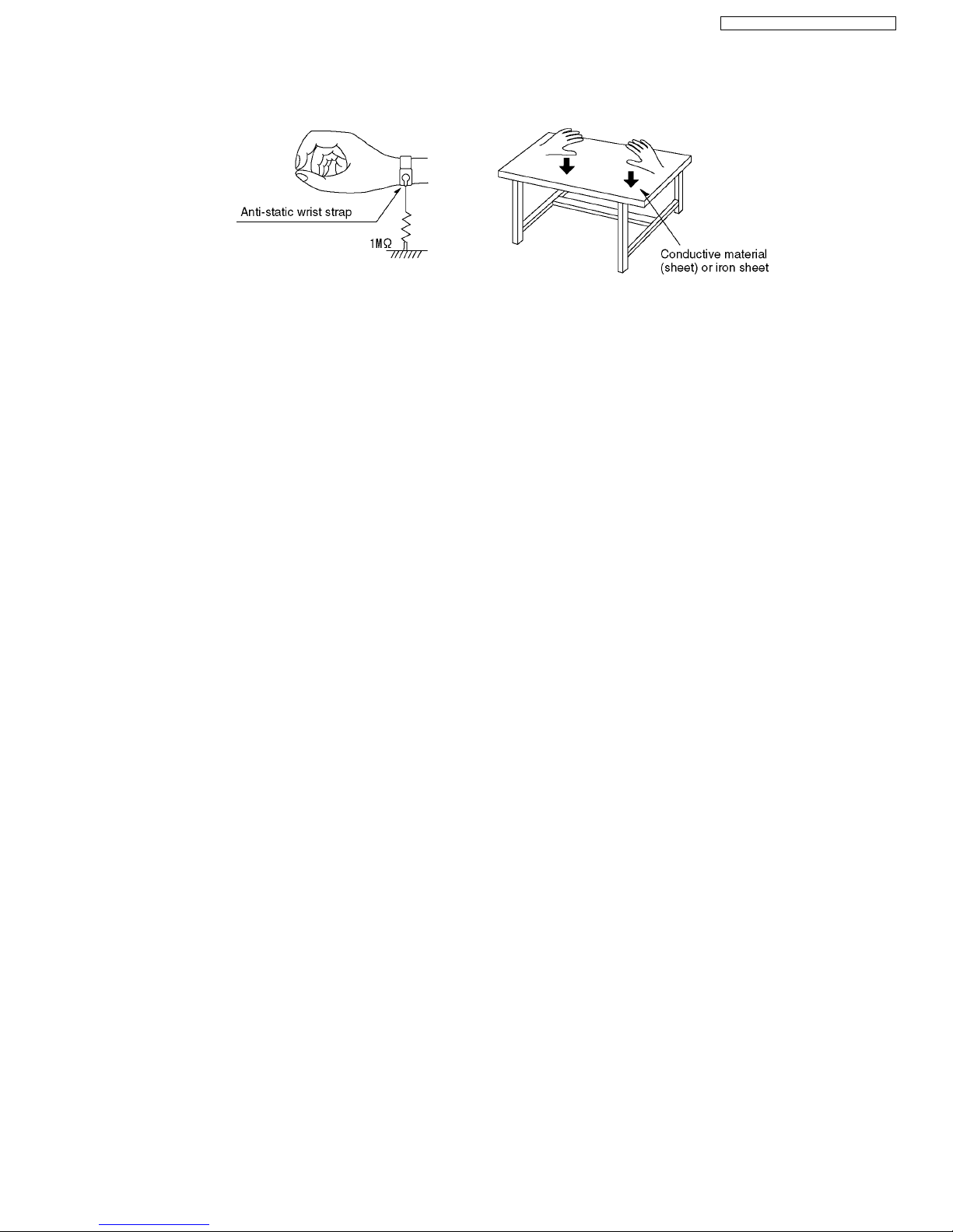
11.3.2. Human body grounding
1. Use the anti-static wrist strap to discharge the static electricity form your body.
13
SA-HT870E / SA-HT870EB / SA-HT870EG
12 DISASSEMBLING THE CASING AND CHECKING P.C.B.S
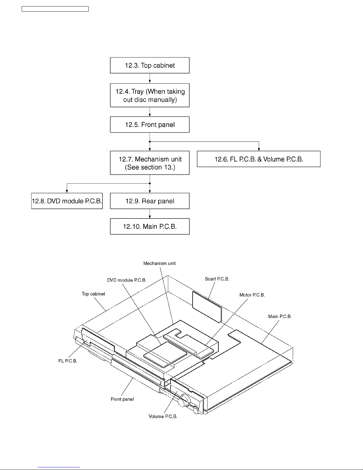
12.1. Disassembly Procedure
12.2. Casing Parts and P.C.B. Positions
14
SA-HT870E / SA-HT870EB / SA-HT870EG
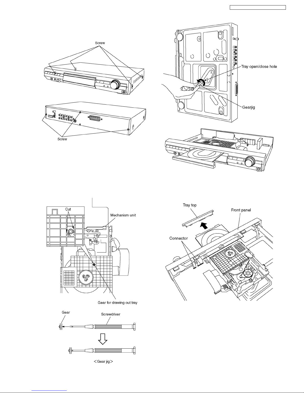
12.3. Top Cabinet
1. Unscrew the screws.
12.4. Tray (When taking out disc
manually)
1. Separates the gear for drawing out tray from the
mechanism unit. It inserts a screwdriver in the gear. (The
gear jig)
2. Insert the gear jig into the tray open/ close hole.
3. Turn the gear jig counterclockwise to open the tray.
12.5. Front Panel
1. Remove the tray top from the tray section.
2. Remove the connectors.
3. Release the tabs.
15
SA-HT870E / SA-HT870EB / SA-HT870EG
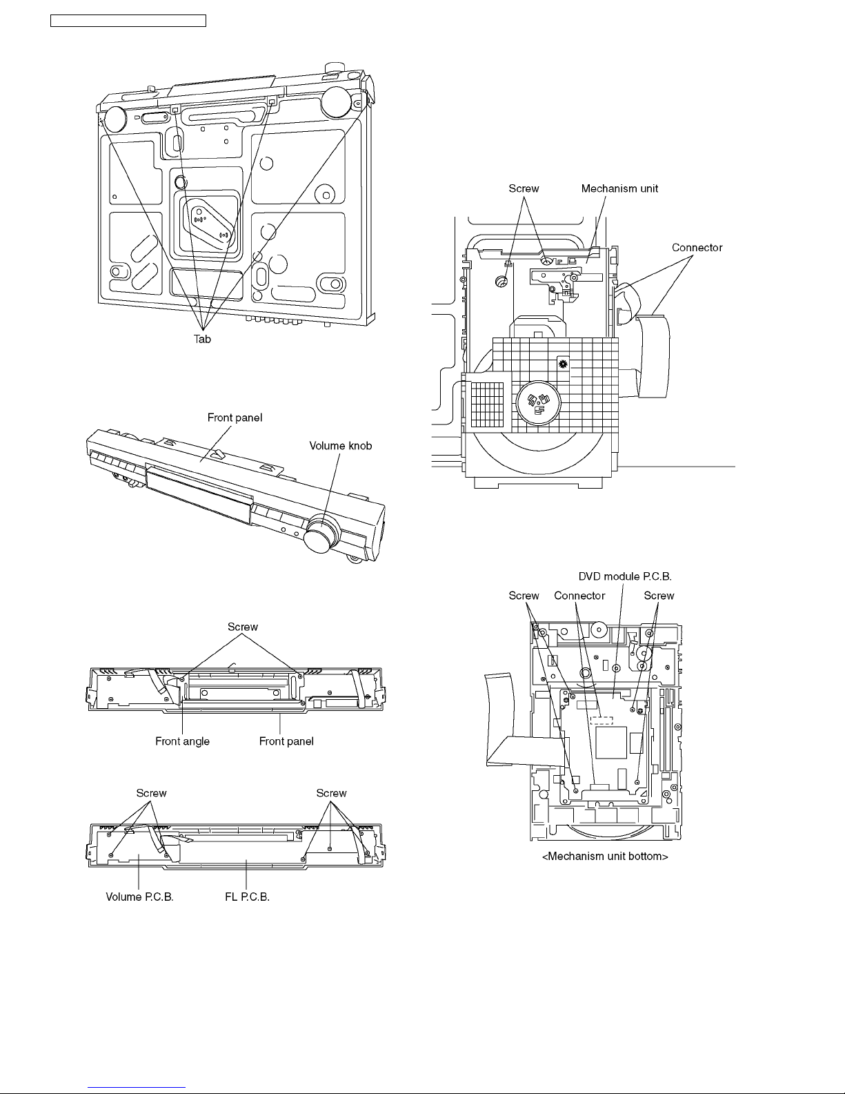
12.6. FL P.C.B. and Volume P.C.B.
1. Remove the volume knob.
2. Unscrew the screws.
3. Remove the front angle.
4. Unscrew the screws.
12.7. Mechanism Unit
1. Turn the gear jig clockwise to close the tray, turn until the
gear jig not to turn.
2. Unscrew the screws.
3. Remove the connectors.
4. Pull out the mechanism unit vertically.
12.8. DVD Module P.C.B.
1. Unscrew the screws.
2. Remove the connectors.
16
SA-HT870E / SA-HT870EB / SA-HT870EG
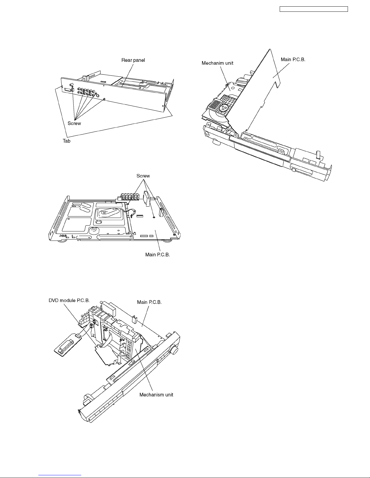
12.9. Rear panel
1. Unscrew the screws.
2. Release the tabs.
12.10. Main P.C.B.
1. Unscrew the screws.
12.11. Service Position
12.11.1. Servici ng position of the DVD
Module P.C.B.
12.11.2. Servici ng positio n of the Main
P.C.B.
17
SA-HT870E / SA-HT870EB / SA-HT870EG
13 ASSEMBLING AND
DISASSEMBLING THE
MECHANISM UNIT
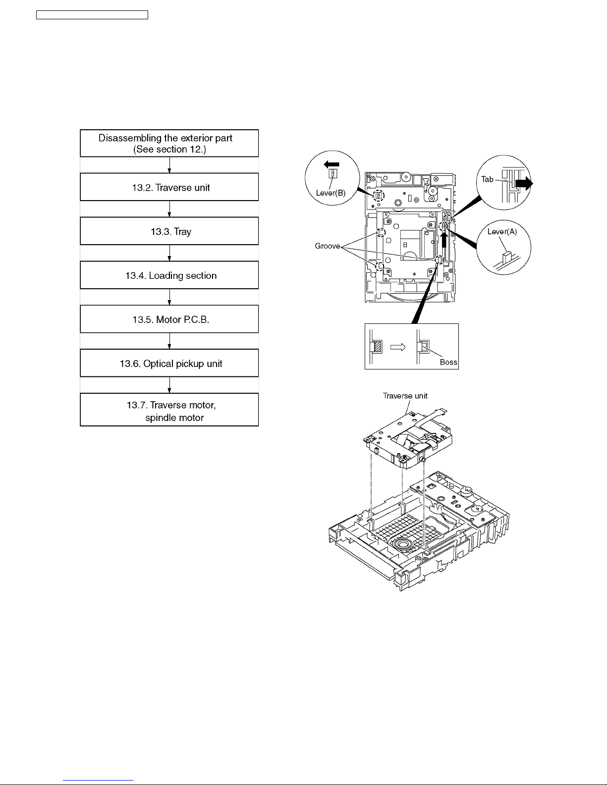
13.1. Disassembly Procedure
13.2. Traverse Unit
1. Slide the lever (A) in the arrow direction (to the opposite
side) till it stops.
2. Slide the lever (A) further by bending the tab at the right
side of the lever A in the right direction. (The right groove
opens and the boss becomes seen.)
3. Open the lever (B) to left. (The 2 grooves at the left side
open.)
4. Remove the traverse unit
18
SA-HT870E / SA-HT870EB / SA-HT870EG
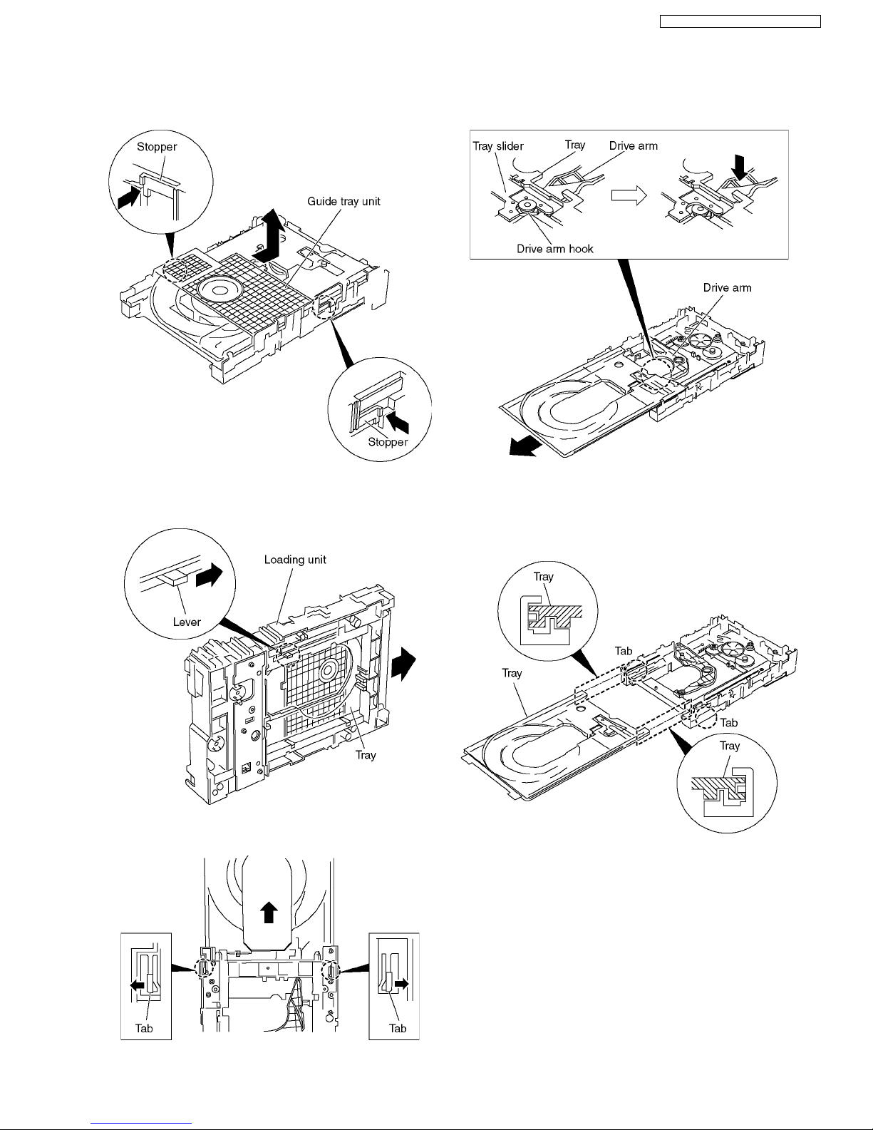
1. Slide the guide tray unit while pressing the stopper in the
arrow direction, and remove the guide tray unit.
2. Raise the loading unit.
3. Slide the lever in the arrow direction till it stops and pull the
tray out.
4. Spread the tabs at the both sides and pull the tray out. (The
tray slides a little forward and stops.)
5. Remove the drive arm concave phase from the tray slider
and tray.
<Assembling the tray unit>
1. Insert a part of the tray into the unit sliding over the
groove on the mechanical chassis unit.
2. Insert the tray to the point before the tab of the
mechanical chassis unit.
13.3. Tray
19
SA-HT870E / SA-HT870EB / SA-HT870EG
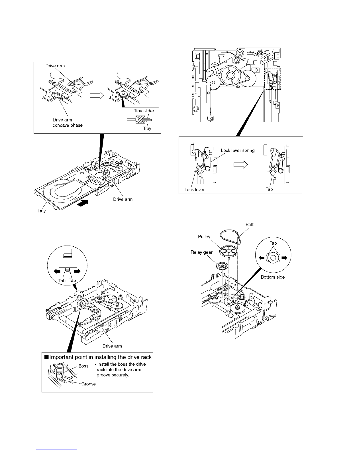
3. Hook the drive arm concave phase over the tray and the
tray slider.
4. Press in the tray.
5. Make sure that the tray and the drive arm move
smoothly.
13.4. Loading section
1. Spread the tabs at the both sides and push out the drive
arm shaft.
2. Hook the lock lever spring on the lock lever projection part
temporarily.
3. Unlock the tab and remove the lock lever.
4. Remove the belt.
5. Unlock the tab and remove the pulley.
6. Remove the relay gear.
20
SA-HT870E / SA-HT870EB / SA-HT870EG
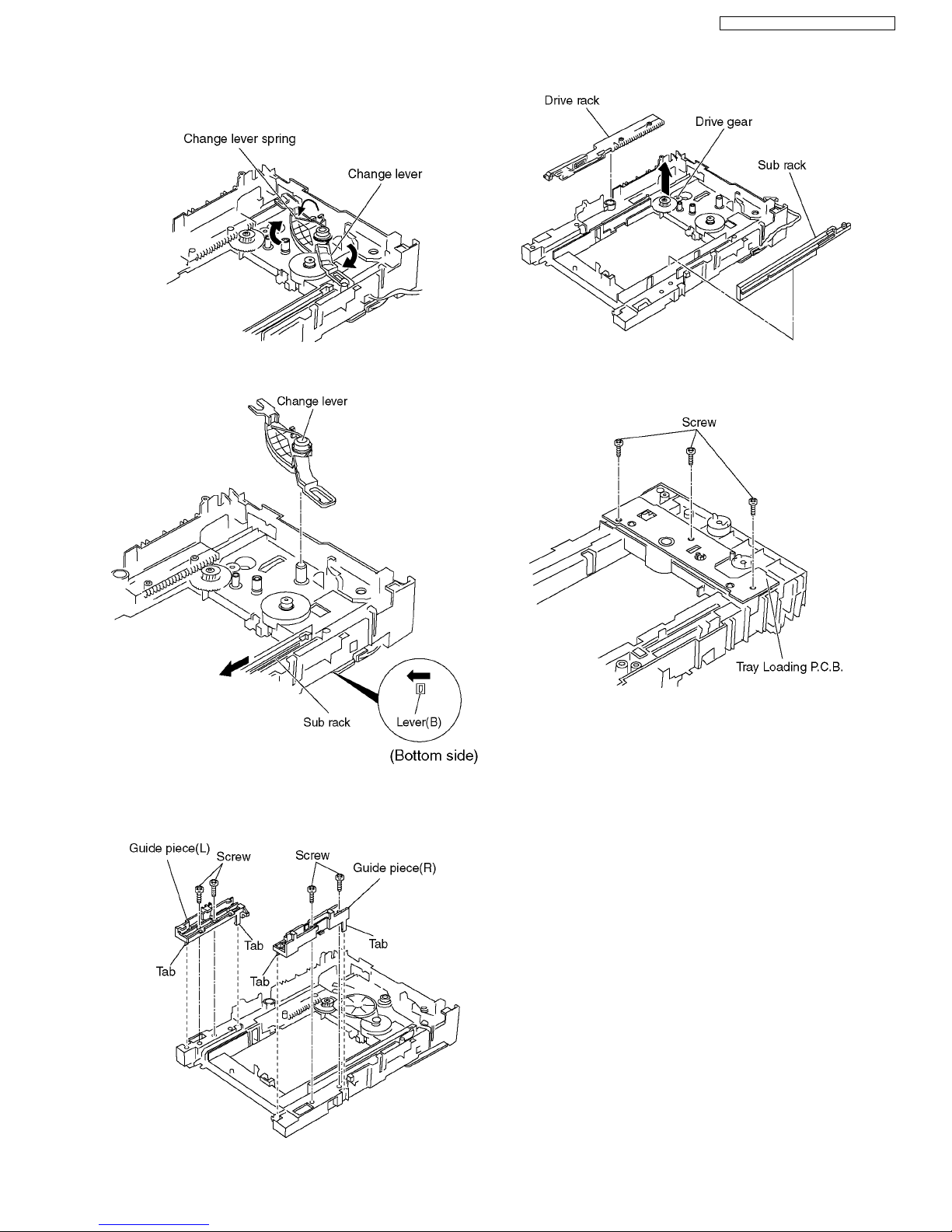
7. Turn the change lever in the arrow direction till it stops.
8. Hook the change lever spring on the change lever project
part temporarily.
9. Pull the lever (B) in thebottom side to your side and remove
the change lever.
10. Unscrew the screws.
11. Unlock the tabs and remove the guide piece (L).
12. Unlock the tabs and remove the guide piece (R).
13. Remove the drive rack, the sub rack and the drive gear.
13.5. Tray Loading P.C.B.
1. Unscrew the screws
21
SA-HT870E / SA-HT870EB / SA-HT870EG
13.6. Optical Pickup Unit
13.6.1. Cautions to Be Taken in Handling the Optical Pickup Unit
The laser diode in the optical pickup unit may be damaged due to electrostatic discharge generating from clothes or human body.
Use due caution to electrostatic discharge damage when servicing the laser diode.
1. Do not give a considerable shock to the optical pickup unit as it has an extremely high-precise structure.
2. To prevent the laser diode from the electrostatic discharge damage, the flexible cable of the optical pickup unit removed from
the PCB should be short-circuited with a short pin or a clip.
3. The flexible cable may be cut off if an excessive force is applied to it. Use caution when handling the flexible cable.
4. The antistatic FPC is connected to the new optical pickup unit. After replacing the optical pickup unit and connecting the flexible
cable, cut off the antistatic FPC.
13.6.2. Cautions to Be Taken When Replacing the Optical Pickup
The flexible cable of the optical pickup unit which was supplied as a component is equipped with a short clip to prevent the laser
diode from being damaged due to electrostatic discharge. Remove the short clip before connecting the flexible cableand make sure
that the short land is open. (If the flexible cable is short-circuited, remove the solder.)
22
SA-HT870E / SA-HT870EB / SA-HT870EG
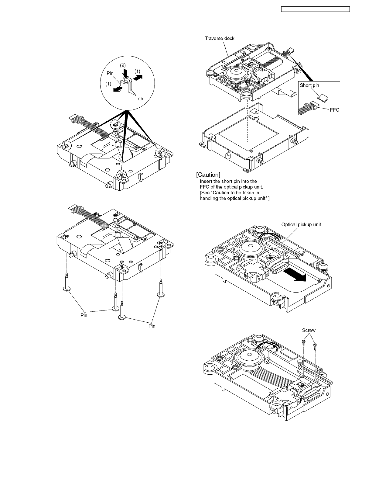
13.6.3. Procedure for Disassembling the
Optical Pickup Unit
1. Spread the tabs to push in the pin.
2. Remove the pins.
3. Remove the traverse deck.
4. Move the optical pickup unit in the arrow direction till it
stops.
5. Unscrew the screws.
23
SA-HT870E / SA-HT870EB / SA-HT870EG

6. Remove the drive rack.
7. Unscrew the screw
8. Slide the shaft in the arrow direction.
9. Lift the optical pickup unit with the shaft.
10. Remove the optical pickup unit.
11. Pull the shaft and the rubber out.
24
SA-HT870E / SA-HT870EB / SA-HT870EG
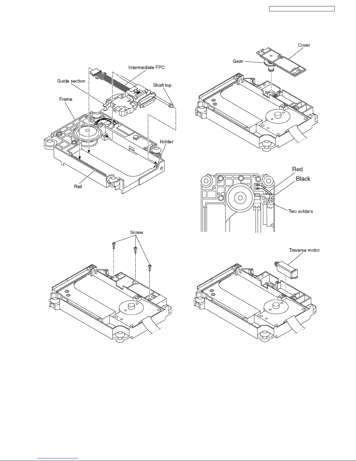
<Assembling the optical pickup unit>
1. Pass the intermediate FPC through the frame hole.
2. Align the guide section of the optical pickup unit withthe
rail.
3. Install the shaft top to the holder.
13.7. Traverse Motor and Spindle
Motor
1. Unscrew the screws.
2. Remove the cover while lifting the inner gear.
3. Remove the solders.
4. Remove the traverse motor.
25
SA-HT870E / SA-HT870EB / SA-HT870EG
 Loading...