

Panasonic SAHT-720-P, SAHT-720-PC Service manual
A
ORDER NO.MD0401026C1
A6
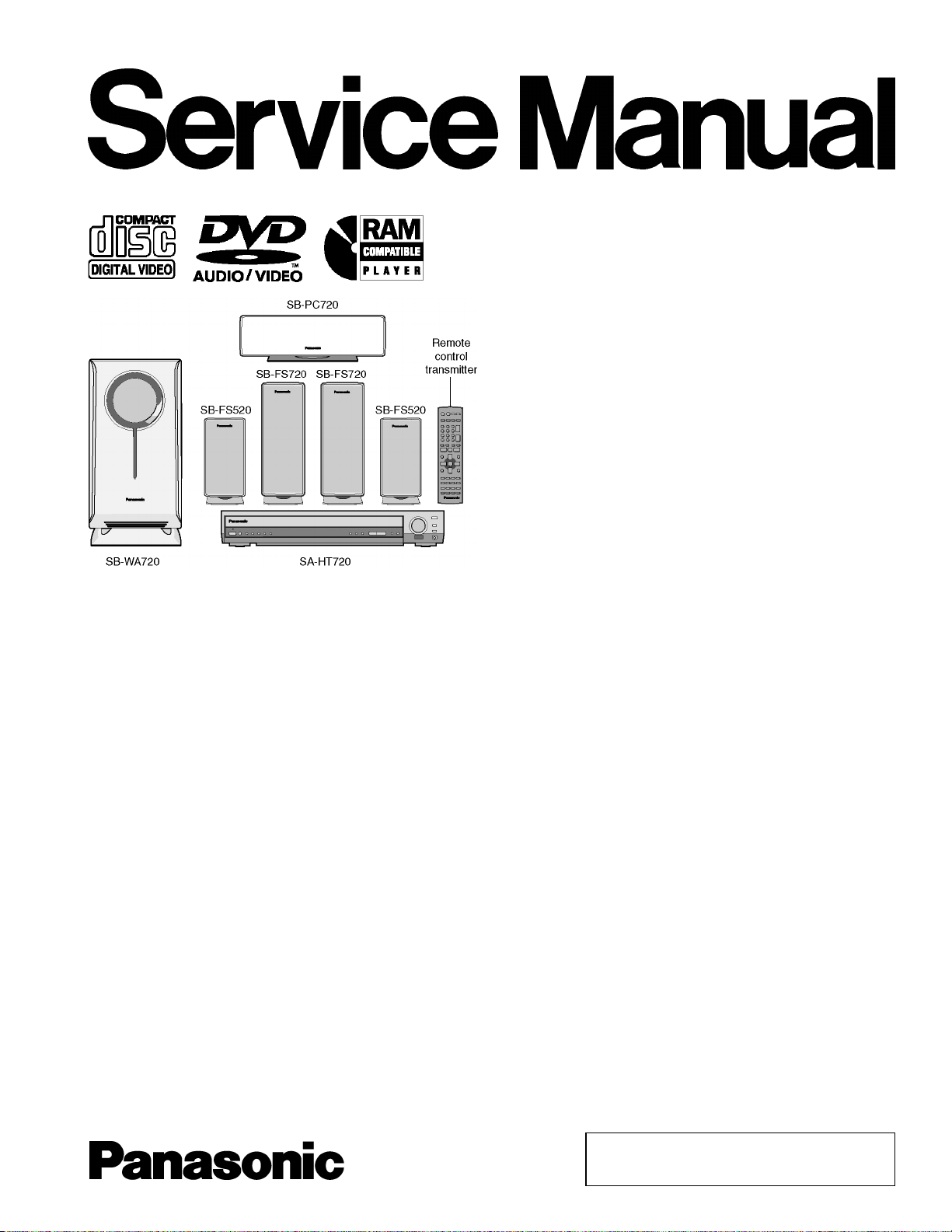
DVD Home Theater Sound System
SA-HT720P
SA-HT720PC
Colour
(S).......................Silver Type
Specifications
lGeneral
Power Source:
Power consumption: 25 W
Dimensions (W×H×D):
Mass:
lAmplifier section
RMS Output Power: Dolby Digital Mode
lTotal RMS Dolby Digital
mode Power:
At 1kHz and total harmonic of 10%
lFront: 70 W/ Channel (4Ω)
lCenter: 260 W/ Channel (4Ω)
lSurround: 70 W/ Channel (4Ω)
At 100Hz and total harmonic of 10%
lActive subwoofers: 260 W/ Channel (4Ω)
FTC Output Power: Dolby Digital Mode:
lTotal FTC Dolby Digital mode Power:
At 120Hz-20kHz and total harmonic of 1%
lFront: 45 W/ Channel (4Ω)
lCenter: 140 W/ Channel (4Ω)
C 120V, 60Hz
430×68×432 mm
(16-15/16”×2-11/16”×17”)
4.1 kg (9.0Ibs)
800 W
470 W
lSurround: 45 W/ Channel (4Ω)
At 45Hz-120Hz and total harmonic of 1%
lSubwoofer: 150 W/ Channel (4Ω)
lFM tuner section
Frequency Range:
Sensitivity: 2.5µV (IHF)
S/N 26dB
Antenna Terminal: 75Ω (non balance)
lAM tuner section
Frequency Range: 520-1710kHz (10kHz in step)
AM Sensitivity S/N 20dB at
999kHz:
Phone Jack:
Terminal:
lDisc section
Discs played [8 cm (3”) or 12 cm (5”)]:
(1) DVD-RAM (DVD-VR compatible, JPEG formatted discs)
(2) DVD-Audio
(3) DVD-Video
87.9-107.9MHz
(200kHz in step)
87.5-108.0MHz
(100kHz in step)
2.2µV
560µV/m
Stereo 3.5mm (1/8”) jack
© 2004 Panasonic AVC Networks Singapore Pte.
Ltd. All rights reserved. Unauthorized copying and
distribution is a violation of law.
V
Y
Y
SA-HT720P / SA-HT720 PC
(4) DVD-R (DVD-Video compatible)
(5) CD-Audio (CD-DA)
(6) Video CD
(7) SVCD (Conforming to IEC62107)
(8) CD-R/CD-RW (CD-DA, Video-CD, SVCD, MP3, WMA, JPEG
formatted discs)
(9) MP3/WMA
lMaximum number of recognizable audio and picture contents
and groups:
lCompatible compression rate:
(10) JPEG
lExif Ver 2.1 JPEG Baseline files
lPicture resolution: between 320 x 240 and 6144 x 4096
pixels (sub sampling is 4:2:2 or 4:2:0)
(11) HighMAT Level 2 (Audio and lmage)
Pick up:
Source of light beam: Semiconductor Laser
Wavelength:
lCD: 785nm
lDVD: 662nm
Audio output (DISC):
Number of channels:
Audio performance:
Frequency response:
DVD (linear audio):
DVD-Audio: 4 Hz-88 kHz (192 kHz
CD-Audio:
S/N ratio:
CD-Audio: 95 dB
Dynamic range:
DVD (linear audio): 95 dB
CD-Audio: 93 dB
Total harmonic distortion:
CD-Audio: 0.005 %
lVideo section
ideo system:
Signal system: NTSC
Composite video output:
Output level: 1 Vp-p (75 Ω)
Terminal: Pin jack (1 system)
4000 audio and picture
contents and 400 groups
MP3: between 32 kbps and 320 kbps
WMA: between 48 kbps and 320 kbps
5.1 ch (FL, FR, C, SL, SR,
SW)
4 Hz-22 kHz (48 kHz sampling)
4 Hz-44 kHz (96 kHz sampling)
sampling)
4 Hz-20 kHz
S-video output:
output level: 1 Vp-p (75 Ω)
C output level: NTSC; 0.286 Vp-p (75 Ω)
Terminal S terminal (1 system)
Component video output (480P/480I):
output level: 1 Vp-p (75 Ω)
P
output level: 0.7 Vp-p (75 Ω)
B
P
output level: 0.7 Vp-p (75 Ω)
R
Terminal: Pin jack (Y: green, PB: blue,
P
: red) (1 system)
R
Power consumption in standby mode:
approx 0.4W
Note:
1. Specifications are subject to change without notice.
Mass and dimensions are approximate.
2. Total harmonic distortion is measured by the digital spectrum
analyzer.
Solder:
This model uses lead free solder (PbF).
2

SA-HT720P / SA-HT720 PC
CONTENTS
Page Page
1 Use of Active Subwoofer 4
1.1. Checking Player when Active Subwoofer is not used
2 Safety Precautions
2.1. GENERAL GUIDELINES
3 Prevention of Electro Static Discharge (ESD) to
Electrostatically Sensitive (ES) Devices
4 Before Repair and Adjustment (Using Active Subwoofer)
5 Protection Circuitry
6 Precaution of Laser Diode
7 About Lead Free Solder (PbF)
8 General Description
8.1. Operating instructions
8.2. Disc information
9 Accessories
10 Handling Precautions for Optical Pickup Unit
10.1. Cautions to Be Taken in Handling the Optical Pickup Unit
10.2. Cautions to Be Taken When Replacing the Optical Pickup
10.3. Grounding for electrostatic breakdown prevention
11 Disassembly and Main Component Replacement Procedures
11.1. Disassembling the Top Cabinet
11.2. Disassembling the Front Panel
11.3. Disassembling the Tray Assembly
11.4. Removal of the Tray Base Guide (L) and Tray Base Guide
(R)
11.5. Removal of the Rotary Tray
11.6. Removal of the Open Lock Gear
11.7. Removal of the Close Lock Gear
11.8. Removal of the Tray Motor P.C.B. and Sensor P.C.B.
11.9. Removal of the CD Traverse Unit
11.10. Removal of the Pulley Gear
11.11. Removal of the Loading Motor P.C.B.
11.12. Removal of the Drive Gear (A) & (B)
11.13. Disassembling the Fixed Plate, Magnet and Clamper
11.14. Removal of the Cam Gear & Support Piece
11.15. Removal of the Slide Plate (L) & (R) and Change Lever
11.16. Assembly of Tray Base
12 DVD-Optical Pick-up Self-Diagnosis and Replacement
Procedure
10
11
11
11
11
13
14
14
14
16
16
16
16
17
17
17
18
18
18
19
19
20
21
4
5
5
5
6
6
7
7
8
8
9
12.1. Optical Pickup Breakdown Diagnosis
12.2. Service Mode Table 1
12.3. DVD Self Diagnostic Function-Error Code
12.4. Last Error Code saved during NO PLAY
12.5. Service mode table 2
12.6. Sales demonstration lock function
12.7. Handling After Completing Repairs
13 Self-Diagnosis Function
13.1. Automatic Displayed Error Codes
13.2. Memorized Error Codes
14 Service Precautions
14.1. Recovery after the DVD player is repaired
14.2. Firmware version-up of the DVD player
15 Adjustment Procedure
15.1. Service Tools and Equipment
15.2. Important points in adjustment
15.3. Storing and Handling Test Discs
15.4. Optical adjustment
16 Abbreviati ons
17 Voltage Chart
17.1. DVD Module P.C.B.
17.2. Main P.C.B.
17.3. FL P.C.B.
17.4. Loading Motor P.C.B.
17.5. Tray Motor P.C.B.
17.6. Sensor P.C.B.
18 Schematic Diagram Notes
19 Block Diagram
20 Schematic Diagram
21 Printed Circuit Board Diagram
22 Wiring Connection Diagram
23 Illustration of IC 痴, Transistors and Diodes
24 Terminal Function of ICs
24.1. IC2018 (C2CBHG000137): Operation CPU
25 Parts Location and Replacement Parts List
25.1. Loading Mechanism, Traverse Unit & Cabinet
25.2. Component Parts List
25.3. Packing Materials & Accessories Parts List
25.4. Packaging
21
22
22
23
24
26
26
27
27
27
28
28
28
29
29
29
29
30
31
33
33
35
36
36
36
37
38
39
45
53
57
59
60
60
61
62
66
75
75
3
SA-HT720P / SA-HT720 PC
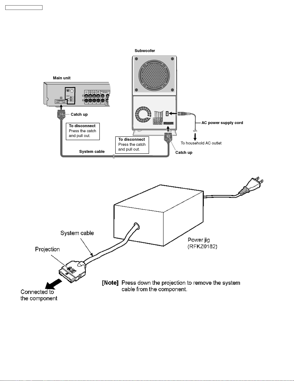
1 Use of Active Subwoofer
1.1. Checking Player when Active Subwoofer is not used
1. This unit uses the active subwoofer to supply the power of the component, and the active subwoofer should be connected to
the component to check operational conditions of the component.
2. If the active subwoofer is not available due to repair of the unit, use the following equipment.
Jig product number: RFKZ0182 (110V, 127V, 220V, 230V-240V for overseas domestic use)
4
SA-HT720P / SA-HT720 PC
2 Safety Precautions
2.1. GENERAL GUIDELINES
1. When servicing, observe the original lead dress. If a short circuit is found, replace all parts which have been overheated or
damaged by the short circuit.
2. After servicing, see to it that all the protective devices such as insulation barriers, insulation papers shields are properly
installed.
3. After servicing, make the following leakage current checks to prevent the customer from being exposed to shock hazards.
2.1.1. LEAKAGE CURRENT COLD
CHECK
1. Unplug the AC cord and connect a jumper between the two
prongs on the plug.
2. Measure the resistance value, with an ohmmeter, between
the jumpered AC plug and each exposed metallic cabinet
part on the equipment such as screwheads, connectors,
control shafts, etc. When the exposed metallic part has a
return path to thechassis, the reading should be between
1MΩ and 5.2MΩ.
When the exposed metal does not have a return path to
the chassis, the reading must be
Figure 1
.
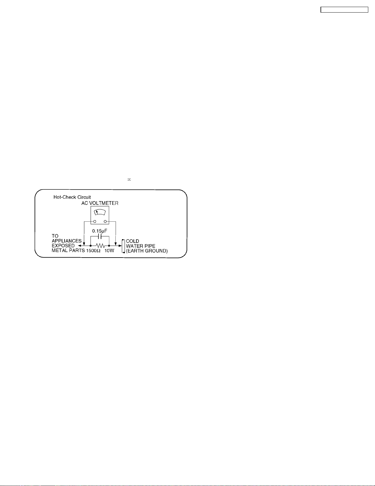
2.1.2. LEAKAGE CURRENT HOT CHECK
(See Figure 1 .)
1. Plug the AC cord directly into the AC outlet. Do not use an
isolation transformer for this check.
2. Connect a 1.5kΩ, 10 watts resistor, in parallel with a 0.15µF
capacitors, between each exposed metallic part on the set
and a good earth ground such as a water pipe, as shown in
Figure 1 .
3. Use an AC voltmeter, with 1000 ohms/volt or more
sensitivity, to measure the potential across the resistor.
4. Check each exposed metallic part, and measure the
voltage at each point.
5. Reverse the AC plug in the AC outlet and repeat each of the
above measurements.
6. The potential at any point should not exceed 0.75 volts
RMS. A leakage current tester (Simpson Model 229 or
equivalent) may be used to make the hot checks, leakage
current mu3st not exceed 1/2 milliamp. In case a
measurement is outsideof the limits specified, there is a
possibility of a shock hazard, and the equipment should be
repaired and rechecked before it is returned to the
customer.
3 Prevention of Electro Static Discharge (ESD) to
Electrostatically Sensitive (ES) Devices
Some semiconductor (solid state) devices can be damaged easily by static electricity. Such components commonly are called
Electrostatically Sensitive (ES) Devices. Examples of typical ES devices are integrated circuits and some field-effect transistorsand
semiconductor "chip" components. The following techniques should be used to help reduce the incidence of component damage
caused by electro static discharge (ESD).
1. Immediately before handling any semiconductor component or semiconductor-equipped assembly, drain off any ESD on your
body by touching a known earth ground. Alternatively, obtain and wear a commercially available dischargingESD wrist strap,
which should be removed for potential shock reasons prior to applying power to the unit under test.
2. After removing an electrical assembly equipped with ES devices, place the assembly on a conductive surface such as
aluminum foil, to prevent electrostatic charge buildup or exposure of the assembly.
3. Use only a grounded-tip soldering iron to solder or unsolder ES devices.
4. Use only an anti-static solder removal device. Some solder removal devices not classified as "anti-static (ESD protected)" can
generate electrical charge sufficient to damage ES devices.
5. Do not use freon-propelled chemicals. These can generate electrical charges sufficient to damage ES devices.
6. Do not remove a replacement ES device from its protective package until immediately before you are ready to install it. (Most
replacement ES devices are packaged with leads electrically shorted together by conductive foam, aluminum foil or
comparableconductive material).
7. Immediately before removing the protective material from the leads of a replacement ES device, touch the protective material
to the chassis or circuit assembly into which the device will be installed.
5

SA-HT720P / SA-HT720 PC
Caution
Be sure no power is applied to the chassis or circuit, and observe all other safety precautions.
8. Minimize bodily motions when handling unpackaged replacement ES devices. (Otherwise harmless motion such as the
brushing together of your clothes fabric or the lifting of your foot from a carpeted floor can generate static electricity
(ESD)sufficient to damage an ES device).
4 Before Repair and Adjustment (Using Active Subwoofer)
Disconnect AC power, discharge Power Supply Capacitors C546~C549 through a 10 Ω, 10 W resistor to ground.
DO NOT SHORT-CIRCUIT DIRECTLY (with a screwdriver blade, for instance), as this may destroy solid state devices.
After repairs are completed, restore power gradually using a variac, to avoid overcurrent.
Current consumption at AC 120 V, 60 Hz in NO SIGNAL mode should be ~ 1000 mA.
5 Protection Circuitry
The protection circuitry may have operated if either of the following conditions are noticed:
· No sound is heard when the power is turned on.
· Sound stops during a performance.
The function of this circuitry is to prevent circuitry damage if, for example, the positive and negative speaker connection wires are
“shorted”, or if speaker systems with an impeda nce less than the indicated rated impedance of the amplifier are used.
If this occurs, follow the procedure outlines below:
1. Turn off the power.
2. Determine the cause of the problem and correct it.
3. Turn on the power once again after one minute.
Note:
When the protection circuitry functions, the unit will not operate unless the power is first turned off and then on again.
6
SA-HT720P / SA-HT720 PC
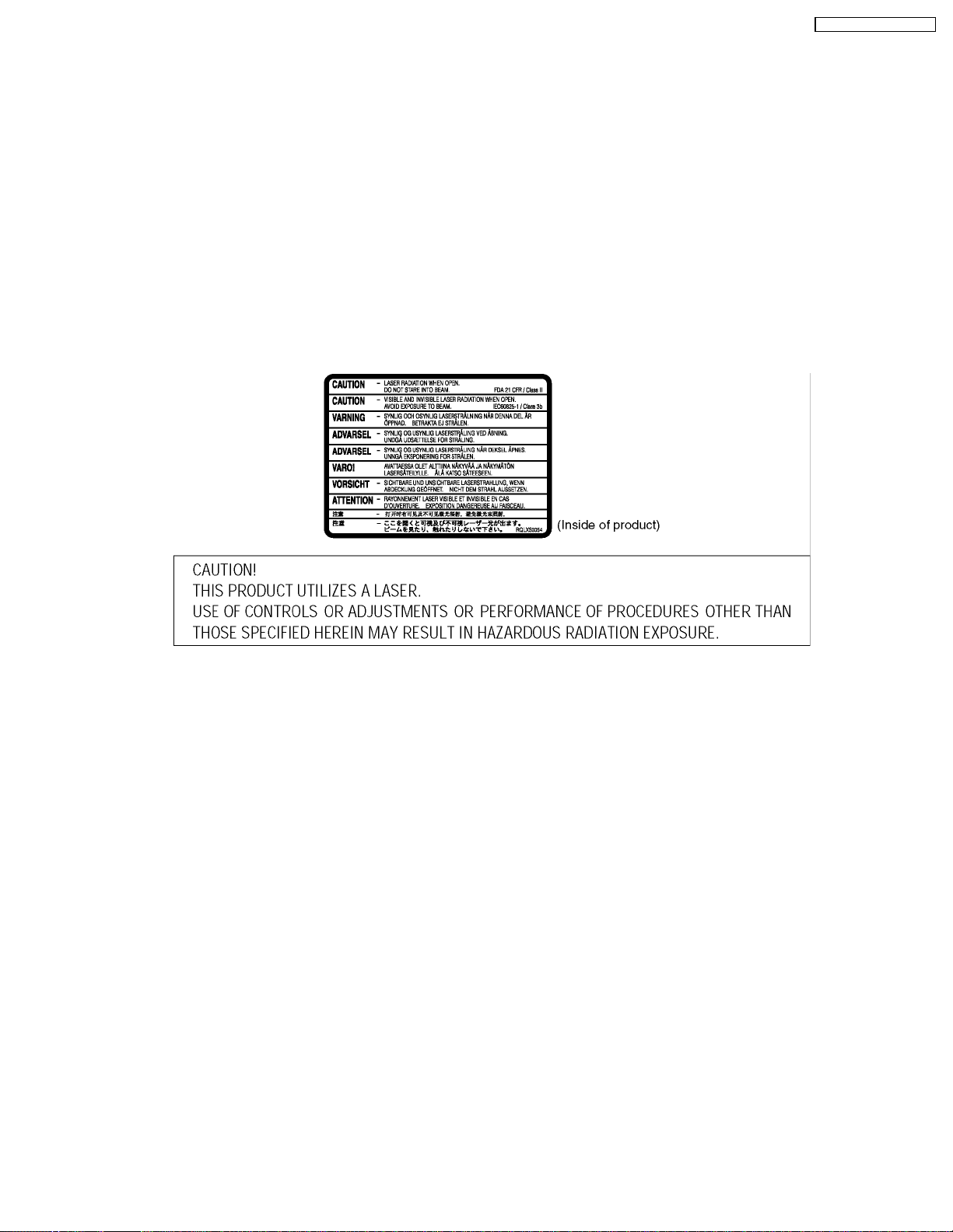
6 Precaution of Laser Diode
CAUTION:
This unit utilizes a class 1 laser.
Invisible laser radiation is emitted from the optical pickup lens.
Wavelength: 662nm(DVD)/785nm(VCD/CD).
Maximum output radiation power from pickup: 100µW/VDE
When the unit is turned on:
1. Do not look directly into the pick up lens.
2. Do not use optical instruments to look at the pick up lens.
3. Do not adjust the preset variable resistor on the pickup lens.
4. Do not disassemble the optical pick up unit.
5. If the optical pick up is replaced, use the manufacturer’s specified replacement pick up only.
6. Use of control or adjustments or performance of procedures other than those specified herein may result in hazardous
radiation exposure.
7 About Lead Free Solder (PbF)
Distinction of PbF PCB: PCBs (manufacture d) using lead free solder will have a Pbf stamp on the PCB.
Caution:
· Pb free solder has a higher melting point than standard solder; Typically the melting point is 50 - 70°F (30 - 40°C) higher.
Please use a high temperature soldering iron. In case of the soldering iron with temperature control,please set it to 700 ±
20°F (370 ± 10°C).
· Pb free solder will tend to splash when heated too high (about 1100°F/ 600°C).
When soldering or unsoldering, please completely remove all of the solder on the pins or solder area, and be sure to heat the
soldering points with the Pb free solder until it melts enough.
7
SA-HT720P / SA-HT720 PC
8 General Description
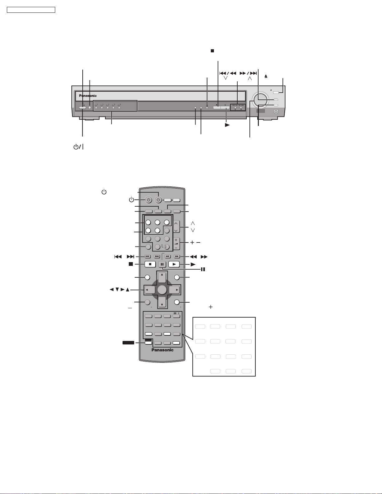
8.1. Operating instructions
STANDBY/ON INDICATOR
INPUT SELECTOR
STOP/
FM MODE
CD MODE/
TUNE MODE
DISC EXCHANGE
,
TUNING
OPEN/CLOSE
INPUT
1 2 3 4 5
SELECTOR
POWER
/I
5 DISC SELECTOR
5 DISC SELECTOR
INDICATIOR
STANDBY/ ON
()
POWER
,
/AV SYSTEM
AUX
TV/VIDEO
DISC 1-5
Numbered
buttons
CANCEL
,
/
AV SYSTEM
TV/VIDEO
TUNER/BAND
AUX
DISC 1 DISC 2 DISC 3
123
DISC 4 DISC 5
456
7809
ENTER
CANCEL
SLOW/SEARCH
SKIP
VCR
TV
DVD/CD
CH
VOLUME
10
C.S.M
PROGRESSIVE
CD MODE
TUNE MODE
C.S.M
PROGRESSIVE
TUNER/BAND
DVD/CD
CH
CH
VOLUME
,
FM MODE MEMORY
TUNING
/
MEMORY
VOLUME
DOWN
VOLUME
OPEN/CLOSE
DISC EXCHANGE
DISC SKIP
UP
PHONES
DISC SKIP
TOP MENU
ENTER
DISPLAY/
TV VOL
SHIFT
TOP MENU
DIRECT
NAVIGATOR
DISPLAY
TV VOL
SUBWOOFER
LEVEL
SLEEP
C.S.M
FL DISPLAY
SHIFT
ENTER
SFC
POSITION
MEMORY
PAGE
GROUP
TEST
CH SELECT
C.FOCUS
SUPER SRND
ZOOM
AUDIO
CD MODE
QUICK REPLAY
MENU
PLAY
LIST
RETURN
TV VOL
MIX 2CH
PL
SETUP
MUTING
REPEAT
PLAY MODE
SUBTITLE
MENU
RETURN/
TV VOL
SUBWOOFER
LEVEL
SLEEP
C.S.M
FL DISPLAY
SFC
POSITION
MEMORY
PAGE
GROUP
TEST
CH SELECT
C.FOCUS
SUPER SRND
ZOOM
AUDIO
CD MODE
QUICK REPLAY
MIX 2CH
PL
SETUP
MUTING
REPEAT
PLAY MODE
SUBTITLE
8
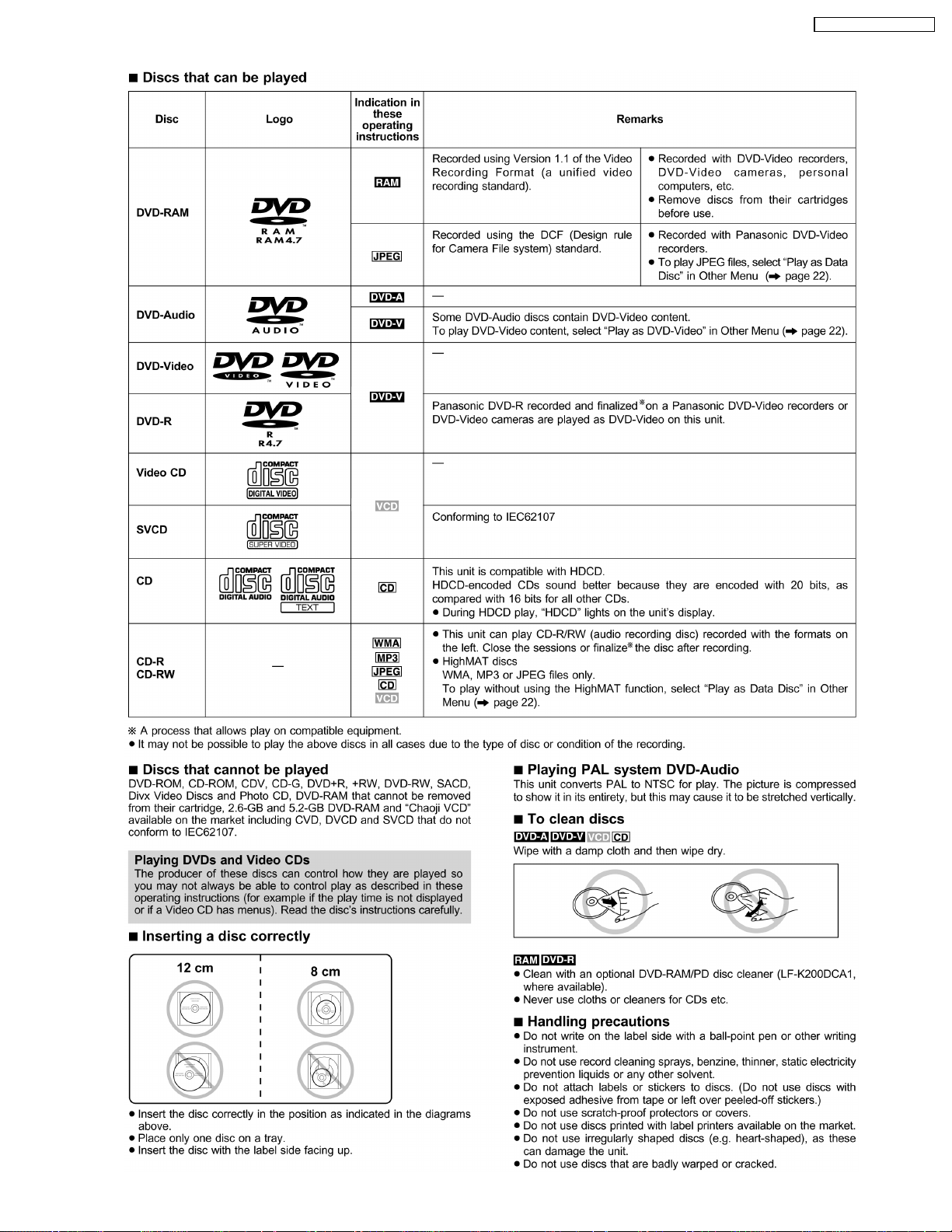
8.2. Disc information
SA-HT720P / SA-HT720 PC
9
SA-HT720P / SA-HT720 PC
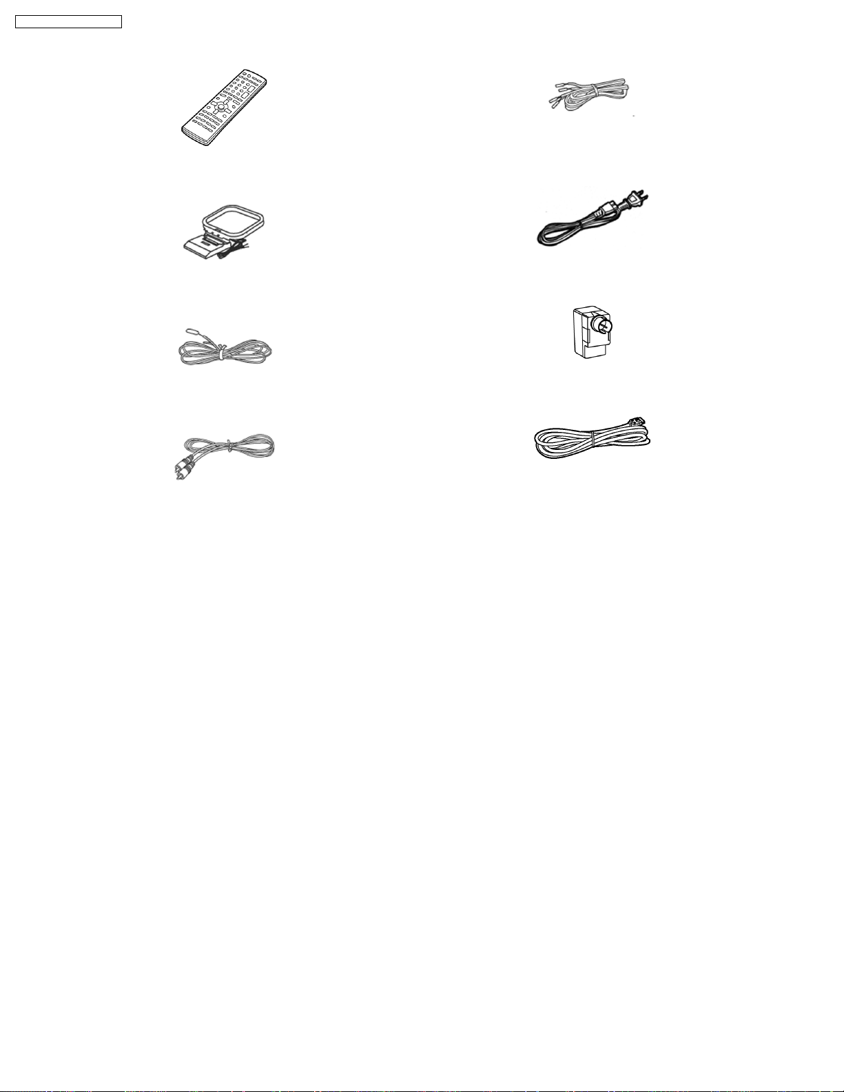
9 Accessories
5 Speaker cables
(4m×3, 10m×2)
Remote control
AC power supply cord
AM loop antenna
Antenna plug
FM indoor antenna
Video Cable
System cable
10
SA-HT720P / SA-HT720 PC
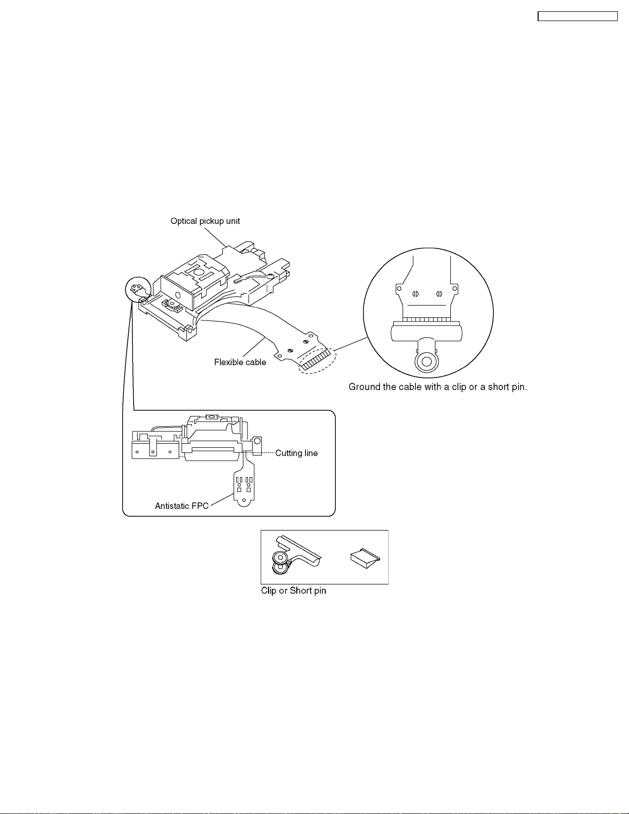
10 Handling Precautions for Optical Pickup Unit
The laser diode in the optical pickup unit may brake down due to static electricity of clothes or human body. Use due caution to
electrostatic breakdown when servicing and handlin g the laser diode.
10.1. Cautions to Be Taken in Handling the Optical Pickup Unit
The laser diode in the optical pickup unit may be damaged due to electrostatic discharge generating from clothes or human body.
Use due caution to electrostatic discharge damage when servicing the laser diode.
1. Do not give a considerable shock to the optical pickup unit as it has an extremely high-precise structure.
2. To prevent the laser diode from the electrostatic discharge damage, the flexible cable of the optical pickup unit removed from
the PCB should be short-circuited with a short pin or a clip.
3. The flexible cable may be cut off if an excessive force is applied to it. Use caution when handlin g the flexible cable.
4. The antistatic FPC is connected to the new optical pickup unit. After replacing the optical pickup unit and connecting the flexible
cable, cut off the antistatic FPC.
10.2. Cautions to Be Taken When Replacing the Optical Pickup
The flexible cable of the optical pickup unit which was supplied as a component is equipped with a short clip to prevent the laser
diode from being damaged due to electrostatic discharge. Remove the short clip before connecting the flexible cableand make sure
that the short land is open. (If the flexible cable is short-circuited, remove the solder.)
10.3. Grounding for electrostatic breakdown prevention
Some devices such as the DVD player use the optical pickup (laser diode) and the optical pickup will be damaged by static
electricity in the working environment. Proceed servicing works under the working environment where grounding works is
completed.
10.3.1. Worktable grounding
1. Put a conductive material (sheet) or iron sheet on the area where the optical pickup is placed, and ground the sheet.
11

SA-HT720P / SA-HT720 PC
10.3.2. Human body grounding
1. Use the anti-static wrist strap to discharge the static electricity form your body.
12

SA-HT720P / SA-HT720 PC
11 Disassembly and Main Component Replacement
Procedures
“ATTENTION SERVICER”
Some chassis components may have sharp edges.
Be careful when disassembling and servicing.
1. This section describes procedures for checking the operation of the major printed circuit boards and replacing the
main components.
2. For assembly after operation checks or replacement, revers e the respective procedures.
Special reassembly procedures are described only when required.
3. Select items from the following index when checks or replacement are required.
· Disassembly the Top Cabinet
· Disassembly the Front Panel
· Disassembly the Tray Assembly
· Removal of the Tray Base Guide (L) and Tray Base Guide (R)
· Removal of the Rotary Tray
· Removal of the Open Lock Gear
· Removal of the Close Lock Gear
· Removal of the Tray Motor P.C.B.and Sensor P.C.B.
· Removal of the CD Traverse Unit
· Removal of the Pulley Gear
· Removal of the Loading Motor P.C.B.
· Removal of the Drive Gear (A) & (B)
· Disassembly the Fixed Plate, Magnet and Clamper
· Removal of the Cam Gear & Support Piece
· Removal of the Slide Plate (L) & (R) and Changer Lever
· Assembly of Tray Base
13
SA-HT720P / SA-HT720 PC
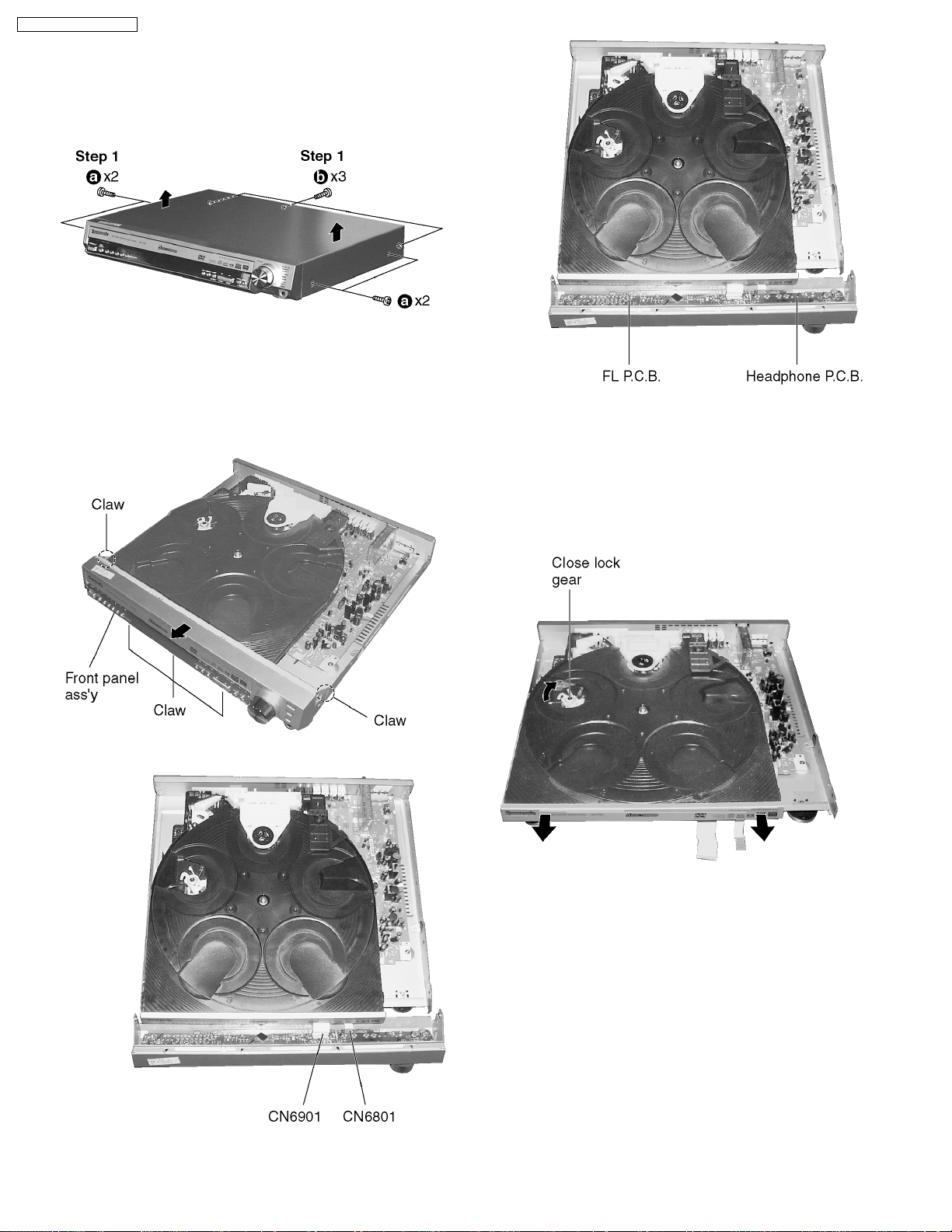
11.1. Disassembling the Top
Cabinet
Step 1 Remove 7 screws.
Step 2 Remove the top cabine t in the direction of arrow.
11.2. Disassembling the Front Panel
· Follow the (Step 1) - (Step 2) of Item 11.1.
Step 1 Pull the front panel ass’y in both direction of arrow to
unlock the claws of the chassis ass’y.
Step 2 Remove the front panel ass’y in the direction of arrow.
11.3. Disassembling the Tray
Assembly
· Follow the (Step 1) - (Step 2) of Item 11.1.
· Follow the (Step 1) - (Step 4) of Item 11.2.
Step 1 Keep the close lock gear pressed in clockwise, move
the tray assembly in the direction of the arrow.
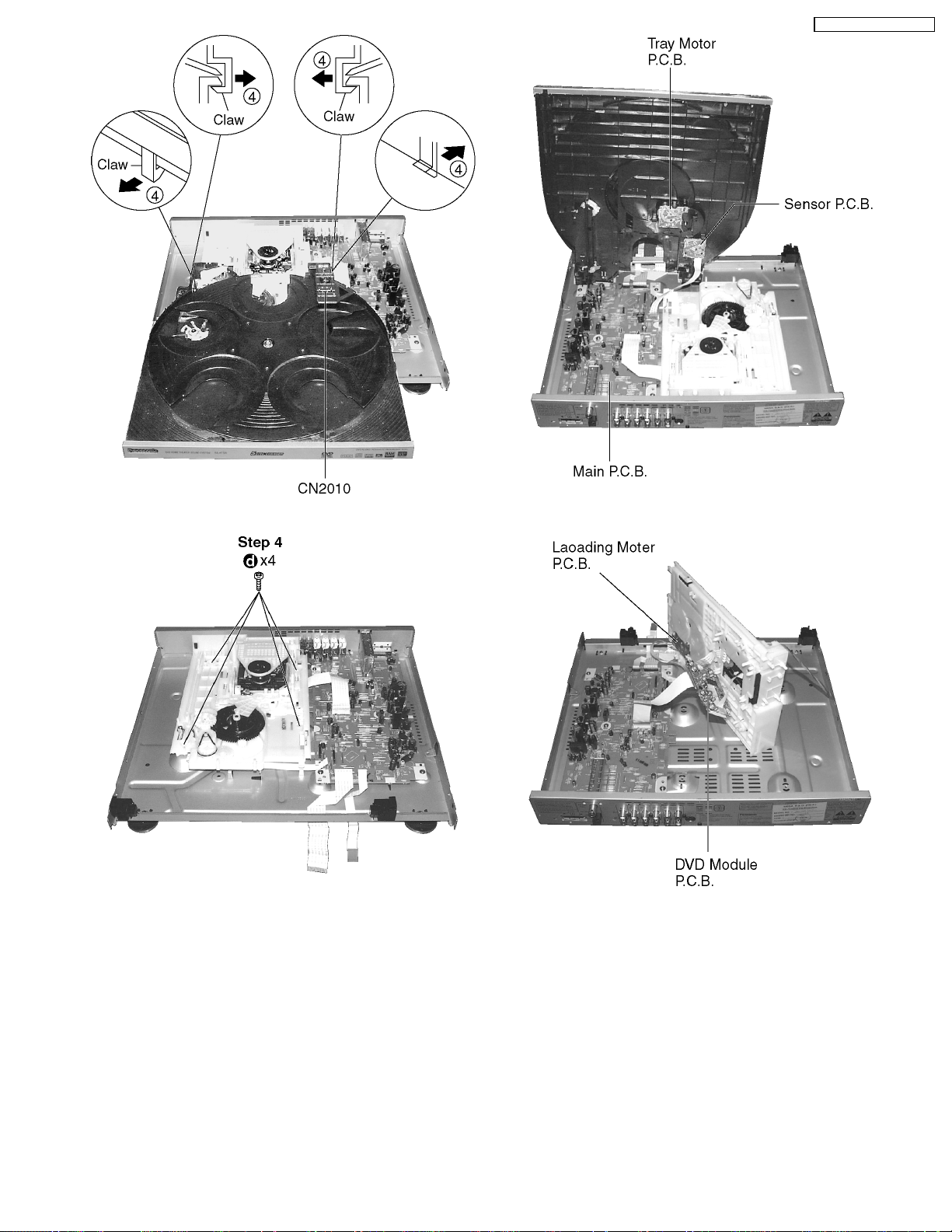
Step 3 Pull out the FFC from connectors (CN6801 & CN6901).
· Checking of Headphone P.C.B. and FL P.C.B.
Step 2 Hold close lock gear, push and release the 4 claws in
the direction of arrow, and then remove the tray assembly.
14
SA-HT720P / SA-HT720 PC
Step 3 Pull out FFC CN6002.
Step 4 Remove 4 screws.
· Checking of Main P.C.B., Tray Motor and Sensor P.C.B.
· Checking of Loading Motor P.C.B. and DVD Module P.C.B.
Step 5 Upset base assembly in vertical position.
15
SA-HT720P / SA-HT720 PC
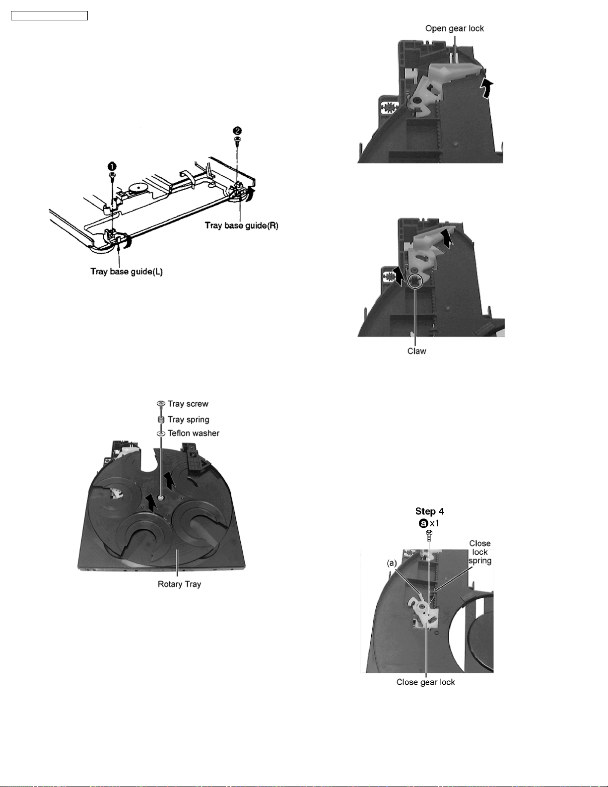
11.4. Removal of the Tray Base
Guide (L) and Tray Base Guide
(R)
· Follow the (Step 1) - (Step 2) of Item 11.1.
· Follow the (Step 1) - (Step 4) of Item 11.2.
· Follow the (Step 1) - (Step 5) of Item 11.3.
Step 1 Remove the 2 screws.
Step 2 Remove the tray base guide (L) and tray guide (R) in the
direction of arrow.
Step 1 Rotate open lock gear in the direction of arrow. (Anticlockwise)
11.5. Removal of the Rotary Tray
· Follow the (Step 1) - (Step 2) of Item 11.1.
· Follow the (Step 1) - (Step 4) of Item 11.2.
· Follow the (Step 1) - (Step 5) of Item 11.3.
Step 1 Remove tray screw, tray spring and teflon washer.
Step 2 Remove rotary tray.
Step 2 Release claw of open lock gear, remove open lock gear
in the direction of arrow.
11.7. Removal of the Close Lock
Gear
· Follow the (Step 1) - (Step 2) of Item 11.1.
· Follow the (Step 1) - (Step 4) of Item 11.2.
· Follow the (Step 1) - (Step 5) of Item 11.3.
· Follow the (Step 1) - (Step 2) of Item 11.5.
Step 1 Remove 1 screw.
11.6. Removal of the Open Lock
Gear
· Follow the (Step 1) - (Step 2) of Item 11.1.
· Follow the (Step 1) - (Step 4) of Item 11.2.
· Follow the (Step 1) - (Step 5) of Item 11.3.
· Follow the (Step 1) - (Step 2) of Item 11.5.
Step 2 Hook close lock spring to claw (a).
16
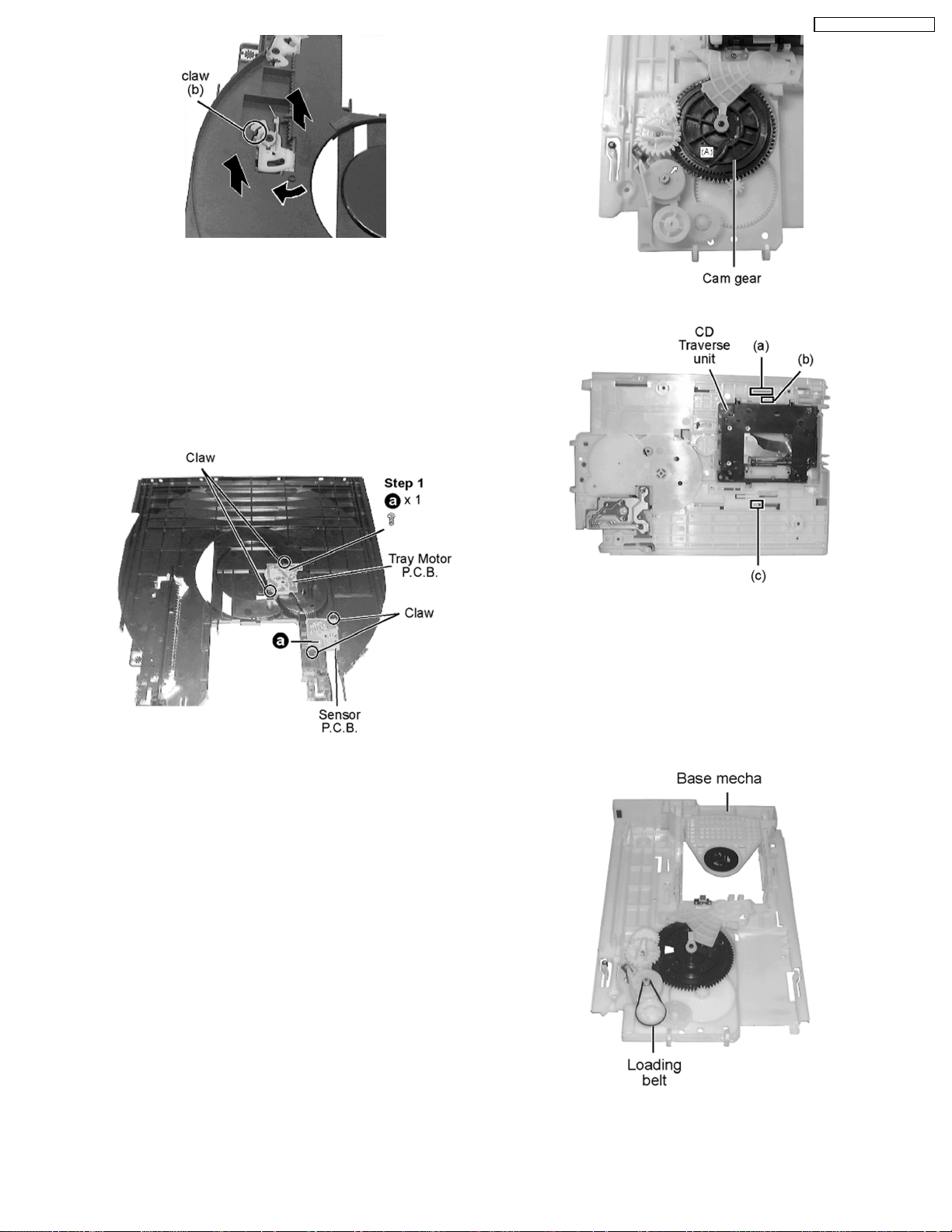
Step 3 Rotate close lock gear to direction of arrow, press claw
(b) and pull out close lock gear.
SA-HT720P / SA-HT720 PC
11.8. Removal of the Tray Motor
P.C.B. and Sensor P.C.B.
· Follow the (Step 1) - (Step 2) of Item 11.1.
· Follow the (Step 1) - (Step 4) of Item 11.2.
· Follow the (Step 1) - (Step 5) of Item 11.3.
Step 1 Remove 2 screws.
Step 2 Release 4 claws at Tray Motor P.C.B. and Sensor
P.C.B.
Step 2 Flip the base mecha unit in vertical position.
Step 3 Press upward (a), push backward (b) and press to left
(c) to release CD traverse unit.
11.10. Removal of the Pulley Gear
· Follow the (Step 1) - (Step 2) of Item 11.1.
· Follow the (Step 1) - (Step 4) of Item 11.2.
· Follow the (Step 1) - (Step 5) of Item 11.3.
Step 1 Remove of the loading belt.
11.9. Removal of the CD Traverse
Unit
· Follow the (Step 1) - (Step 2) of Item 11.1.
· Follow the (Step 1) - (Step 4) of Item 11.2.
· Follow the (Step 1) - (Step 5) of Item 11.3.
Step 1 Rotate cam gear anti-clockwise. (Align at position (A) as
marking on gear with arrow)
Step 2 Flip the base mecha.
17
SA-HT720P / SA-HT720 PC
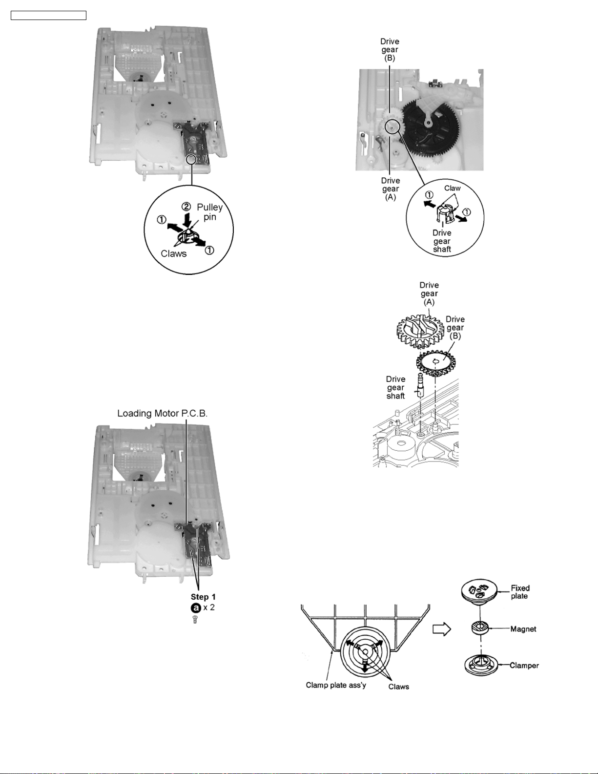
Step 3 Release the 2 claws in the direction of arrow (1), and
then push the pulley pin in the direction of arrow (2).
push drive gear shaft up.
Step 2 Remove Drive Gear (A) and Drive Gear (B).
11.11. Removal of the Loading Motor
P.C.B.
· Follow the (Step 1) - (Step 2) of Item 11.1.
· Follow the (Step 1) - (Step 4) of Item 11.2.
· Follow the (Step 1) - (Step 5) of Item 11.3.
Step 1 Remove 2 screws.
11.13. Disassembling the Fixed Plate,
Magnet and Clamper
· Follow the (Step 1) - (Step 2) of Item 11.1
· Follow the (Step 1) - (Step 4) of Item 11.2.
· Follow the (Step 1) - (Step 5) of Item 11.3.
Step 1 Release 3 claws in the direction of arrow.
Step 2 Remove Loading Motor P.C.B.
11.12. Removal of the Drive Gear (A)
& (B)
· Follow the (Step 1) - (Step 2) of Item 11.1.
· Follow the (Step 1) - (Step 4) of Item 11.2.
· Follow the (Step 1) - (Step 5) of Item 11.3.
Step 1 Release the claw in the direction of arrow (1), and then
18
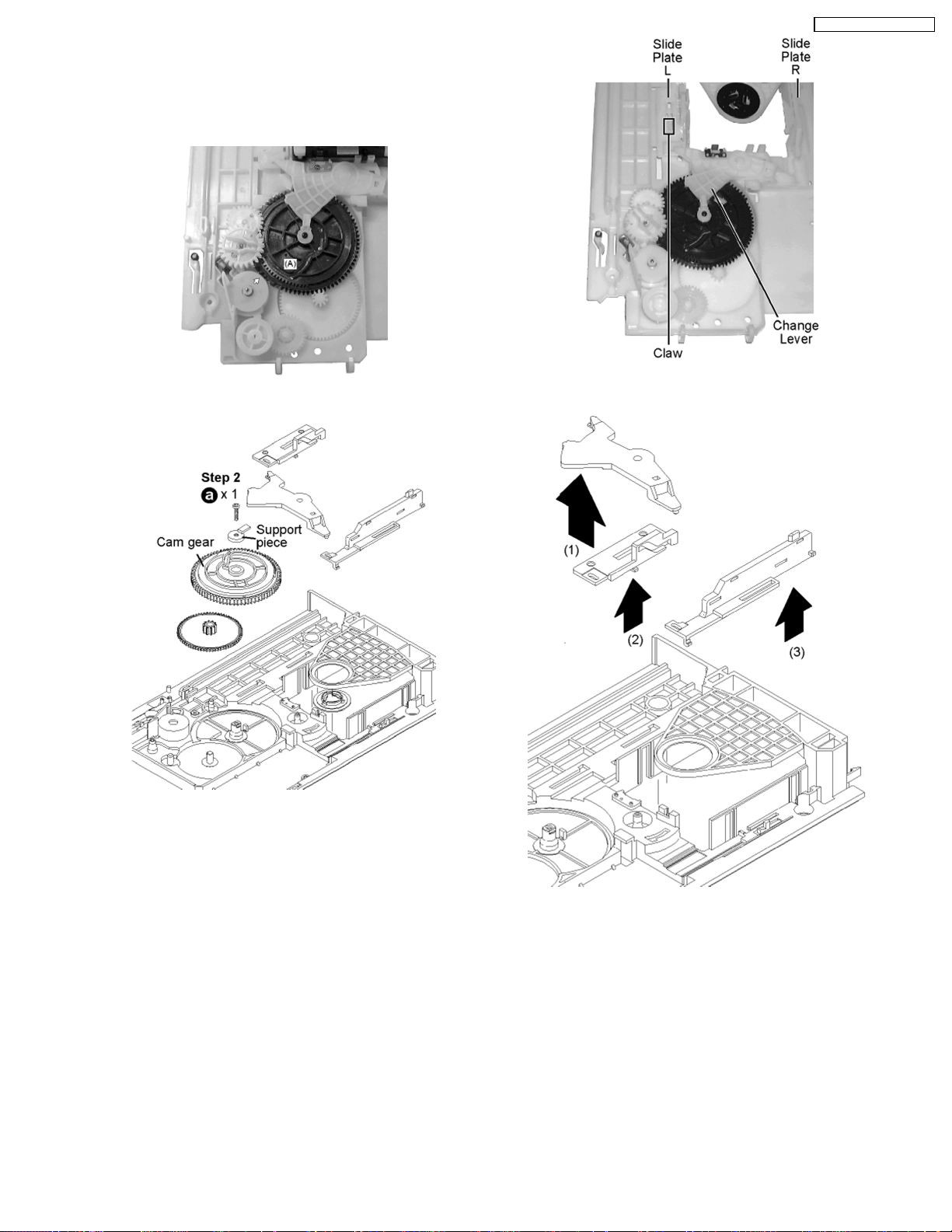
11.14. Removal of the Cam Gear &
Support Piece
· Follow the (Step 1) - (Step 5) of Item 11.3.
Step 1 Rotate (A) in cam gear anti-clockwise.
Step 2 Remove 1 screw and support piece.
SA-HT720P / SA-HT720 PC
Step 2 Remove slide plate (L) & (R) and change lever as arrow
shown.
11.15. Removal of the Slide Plate (L)
& (R) and Change Lever
· Follow the (Step 1) - (Step 5) of Item 11.3.
Step 1 Press the claw and push the Slide Plate (L) up.
19
SA-HT720P / SA-HT720 PC
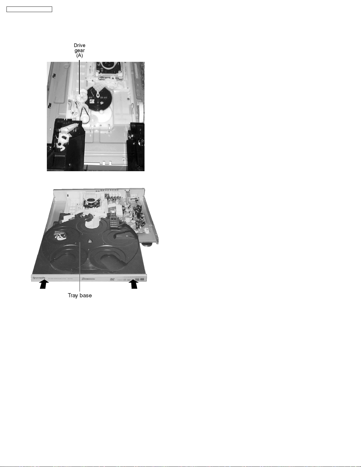
11.16. Assembly of Tray Base
Step 1 Rotate cam gear anti-clockwise. Align at position (C) as
marking on gear with arrow.
Step 2 Make sure drive gear (A) at vertical position.
Step 3 Push tray base to the direction of arrow shown.
20
SA-HT720P / SA-HT720 PC
12 DVD-Optical Pick-up Self-Diagnosis and Replacement
Procedure
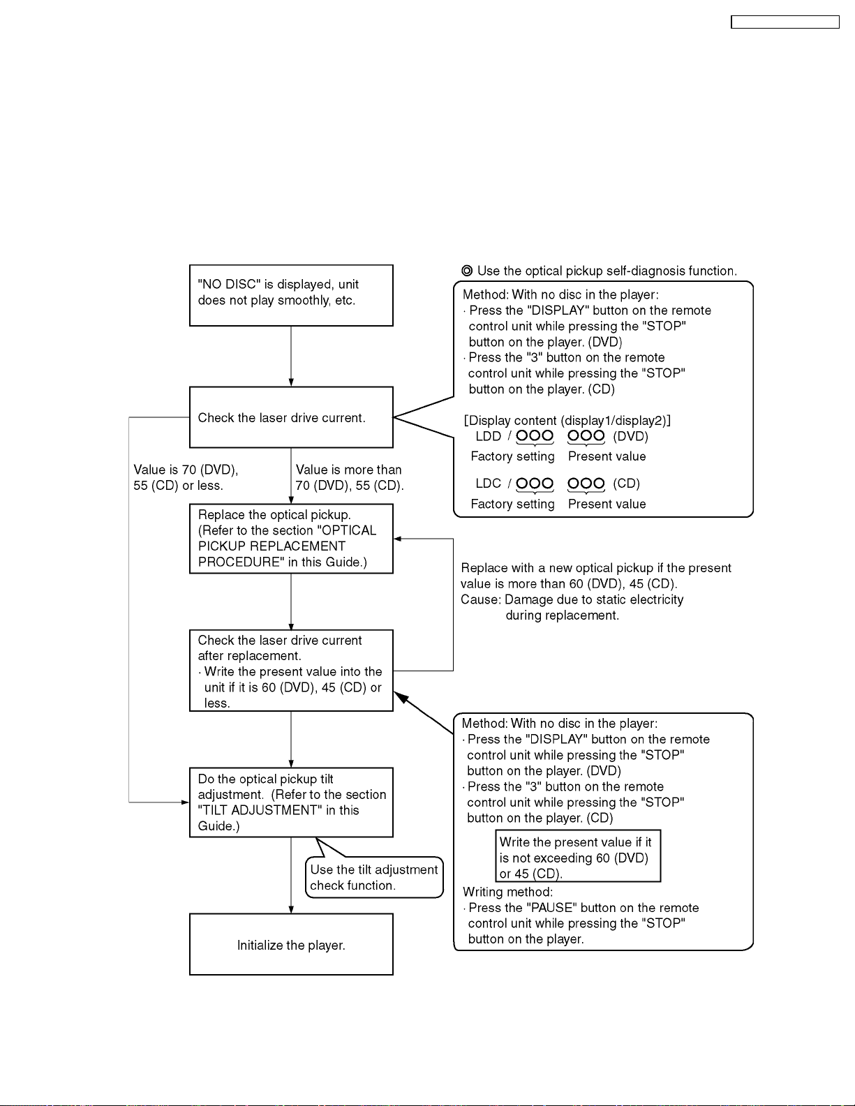
12.1. Optical Pickup Breakdown Diagnosis
The optical pickup self-diagnosis function and tilt adjustment check function have been included in this unit. When repairing, use
the following procedure for effective Self-diagnosis and tilt adjustment.Be sure to use the self-diagnosis functionbefore replacing
the optical pickup when "NO DISC" is displayed. As a guideline, you should replace the optical pickup when the value of the laser
drive current is more than 55.
Note:
Press the power button to turn on the power, and check the value within three minutes before the unit warms up. (Otherwise,
the result will be incorrect.)
21
SA-HT720P / SA-HT720 PC
12.2. Service Mode Table 1
The service modes can be activated by pressing various button combination on the player and remote control unit.
Player buttons Remote control unit buttons Application Note
STOP 0 Error code display (Refer to the item, “12.3.
5 Tilt adjustment Refer to the item “15.4.
6 Area number and broadcasting system check
7 Built-in program version check
DISPLAY DVD laser drive current check Refer to the item “12.1.
3 CD laser drive current check
PAUSE Writing of laser drive current value after replacement of optical
≧10
pickup (Do use this function only when optical pickup is
replaced.)
Initialization of the player (factory setting is restored.)
Used after replacement of micro-computer and its peripherals
and printed circuit board.
DVD Self Diagnostic
Function-Error Code ”).
Optical adjustment”).
Optical Pickup
Breakdown Diagnosis ”.
12.3. DVD Self Diagnostic Function-Error Code
Error Code Error Content Additional error explanation
U, H error
U11 Focus error
H01 Tray loading error
H02 Spindle servo error (Spindle servo, DSC (IC3001) SP motor, CLV servo error)
H03 Traverse servo error
H04 Tracking servo error
H05 Seek error
H06 Power error Cannot switch off the power because of the panel and system computer communication error
H07 Spindle motor drive error
DSC related
F500 DSC error DSC (IC3001) stops in the occurrence of servo error (starup, focus error, etc.)
F501 DSC not Ready DSC-system computer communication error (Communication failure caused by idling of DSC)
F502 DSC Time out error Similar disposal as F500
F503 DSC communication Failure Communication error (result error occurred although communication command was sent)
F504 Error adjusting DSC data slice offset
F505 DSC Attention error Similar disposal as F500
F506 Invalid media Disc is flipped over, TOC unreadable, incompatible disc
ODC related
F600 Access failure to management
information caused by demodulation
error
F601 Indeterminate sector ID requested Operation stopped caused by the request to access abnormal ID data
F602 Access failure to LEAD-IN caused by
demodulation error
F603 Access failure to KEYDET caused by
demodulation error
F610 ODC abnormality No permission for command execution
F611 6626 QCODE don’t read Error Access failure to seek address in CD series
F612 No CRC OK for a specific time Access failure to ID data in DVD series
F620 Laser safeguard: high temperature
condition
F621 Laser safeguard: circuit failure
condition
F630 No reply to KEY DET enquiry (for internal use only)
F631 CPPM KEY DET is not available till
the FILE terminal
F632 CPPM KEY DET is not available Been revoked or falsified
Disc code
F103 Illegal highlight Position Big possibility of disc specification violation during highlight display
HIC Error
F4FF Force initialize failure (time out)
Micro computer error
F700 MBX overflow When replying message to disc manager
F701 Message command does not end Next message is sent before replying to disc manager
F702 Message command changes Message is changed before it is sent as a reply to disc manager
F880 Task number is not appropriate Message coming from a non-existing task
Operation stopped because navigation data is not accessible caused by the demodulation
defect
LEAD IN data unreadable
Access failure to CSS data of disc
(CPPM file system is unreadable caused by scratches)
22

SA-HT720P / SA-HT720 PC
Error Code Error Content Additional error explanation
F890 Sending message when message is
being sent to AV task
F891 Message couldn’t be sent to AV task Begin sending message to AV task
F893 FROM falsification
F894 EEPROM abnormality
F895 Language area abnormality Firm version agreement check for factory preset setting failure prevention
F896 No existence model Firm version agreement check for factory preset setting failure prevention
F897 Initialize is not completed Initialize completion check for factory preset setting failure prevention
F898 Disagreement of hardware and
software
F8A0 Message command is not appropriate Begin sending message to AV task
Sending message to AV task
Unsuitable combination of AV DECORDER, SDRAM and FLASH ROM
(firmware)
Note:
An error code will be canceled if a power supply is turned OFF.
*1: CPPM is the copy guard function beforehand written in the disk for protection of copyrights.
12.4. Last Error Code saved during NO PLAY
Error code Error Content System computer Setting task System computer internal error code
F0BF 6) Cannot playback because
physical layer is not recognizable
F0C0 8) DVD: Cannot playback because it
is not DVD Video/Audio/VR
F0C1 9) DVD: Prohibited by the restricted
region code
F0C2 A) DVD: PAL restricted playback PCND_NOPLAY PAL 0x90 DiscManager 0xDOC2
F0C3 B) DVD: Parental lock setting
prohibits the playback of the entire
title
F0C4 C) VCD: Prohibited because it is in
PHOTO CD format
F0C5 VCD/CD: Prohibited because it is
CDROM without CD-DA
PCND_NOPLAY PHYSICAL
0x50
PCND_NOPLAY VIDEO 0x70 DiscManager 0xDOC0
PCND_NOPLAY RCD 0x80 DiscManager 0xDOC1
PCND_NOPLAY PTL 0xA0 DiscManager 0xDOC3
PCND_NOPLAY PHOTO CD
0xB0
PCND_NOPLAY CDROM 0xC0 DiscManager 0xDOC5
DriveManager 0xDOBF
DiscManager 0xDOC4
23
 Loading...