

Panasonic SA-GX790, SA-GX690, SA-GX490, SA-GX290 Owner’s Manual
Technic
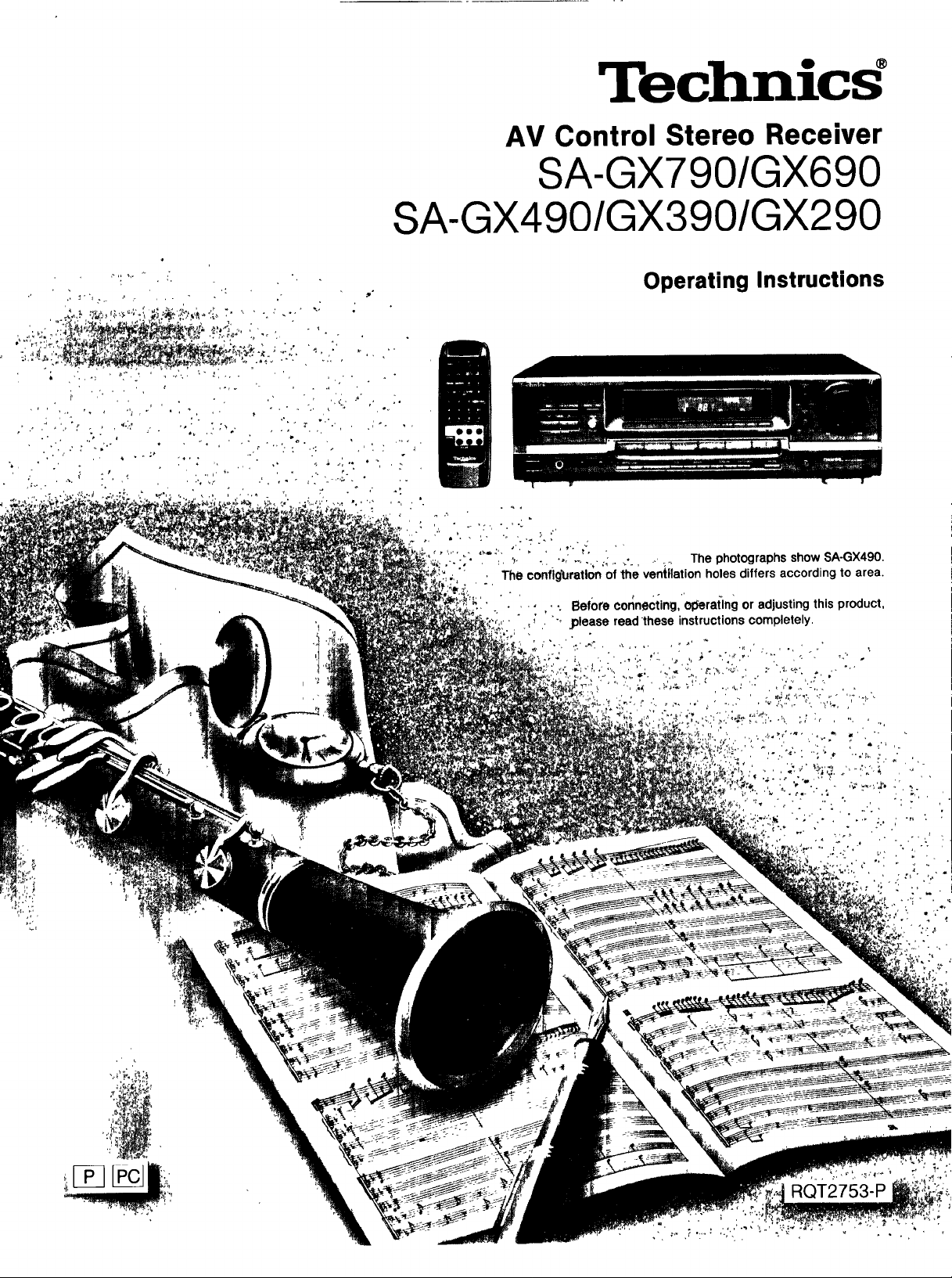
AV Control Stereo Receiver
SA-GX790/GX690
SA-GX490/GX 390/GX290
Operating Instructions
P
, , ,:,, -,,-'
:f. , :, _..... . " _.,,,. j .....¢. , _ , The photographs show SA-GX490.
The configUration of the ventilation holes differs according to area•
!'_' ' " .... . *. Before connecting, olSeratlng or adjusting this product,
, _ ", .please read these instructions completely•
' "7,' °":
4,',' ''_ " '.':" " ,,',,
RQT2753-P
Dear Customer
Thank you for purchasing this Technics product.
For optimum performance and safety, please read
these instructions carefully.
These operating Instructions are applicable to
models SA.GX790, SA.GX690, SA.GX490, SA-GX390
and SA-GX290, however, are Intended primarily for
model SA-GX490.
Precautions ................................. ....... ,3
Accessories ........................................ ,4
Front panel controls .............................. S
Equipment connections .......................... 6
Antenna connections ............................. 8
Speaker connections ............................. 9
Basic operetions .................................. 12
If sound output stops during use or if you are unsure
what to do ............................................ 13
To adjust the tone quality .............................. 13
To mute the sound level ............................... 13
To adjust the sound balance ........................... 13
To emphasize low frequency sound
l.-f_,_et:qrJ_[e)let:(,1=IiJFJ,ql ............................... 13
To listen through headphones .......................... 13
To switch the VCR to the front or rear "VCR 2" terminal
...................................... 13
Listening to redid broadcasts .................... 14
Direct access tuning .................................. 14
Sequential tuning ...................................... 14
Preset tuning ......................................... 15
Enjoying sound with DOLBY PRO LOGIC ..... 17
SURROUND .......................................... 17
3 STEREO ............................................ 17
Setting the center mode ............................... 17
Adjusting speaker output level .......................... 18
Adjusting the delay tlme Ik'f_,_et:f_I)n_.,_l,=.mql ........ 19
Enjoying with SURROUND or 3 STEREO ................. 19
Enjoying sound with SFC
E_,'_r_'_[l_'D[f_[I TJ[4_i_,_(;I_I fll,] i i i,i ................................ 20
Adjusting field of sound ................................ 20
Making a recording ................................ 21
Recording on the tape deck ............................ 21
Recording on the VCR (VCR 1).......................... 21
About the HELP function ....................... .22
About the On-Screen Display function
........................................ 22
Product service .................................... 22
Troubleshooting guide .......................... .23
Technical specifications ............. _.Back cover
The model number and serial number of this product can be
found on either the back or the bottom of the unit.
Please note them in the space provided below and retain
them for future reference.
MODEL NUMBER .......................................
SERIAL NUMBER .......................................
THIS PHRASE IS APPLIED ONLY FOR U.S.A.:,
CAUTION:
Any unauthorized changes or modifications to this equipment
would void the user's authority to operate this device.
WARNING:
TO REDUCE THE RISK OF FIRE OR
ELECTRIC SHOCK, DO NOT EXPOSE THIS
APPLIANCE TO RAIN OR MOISTURE.
CAUTION:
TO PREVENT ELECTRIC SHOCK MATCH
WIDE BLADE OF PLUG TO WIDE SLOT,
FULLY INSERT.
CAUTION
CAUTION: TO REDUCE TH E RISK OF ELECTRIC
SHOCK, DO NOT REMOVE SCREWS.
NO USER-SERVICEABLE PARTS
INSIDE.
REFER SERVICING TO QUALIFIED
SERVICE PERSONNEL.
A The lightning flashwitharrowheadsymbol, within
_'_ anequilateraltriangle,isintendedtoalertthe user
• P_ tothepresenceofuninsulated"dangerousvoltage"
IL. withintheproduct'senclosurethat maybe ofsuffi-
i cientmagnitudetoconstitutea riskof electricshock
to persons.
Is intendedto alert the user to the presence of
importantoperating and maintenance(servicing)
__IL Theexclamationpointwithinanequilateraltriangle
instructionsinthe literatureaccompanyingtheap-
pliance.
2
Before using this unit please read these operating instructions
carefully. Take special care to follow the warnings indicated on
the unit itself as well as the safety suggestions listed below.
Afterwards keep them handy for future reference.
Safety
1. Power Source -- The unit should be connected to power sup-
ply only of the type described in the operating instructions or
as marked on the unit.
2. Polarization -- If the unit is equipped with a polarized AC
power plug (a plug having one blade wider than the other),
that plug will fit into the AC outlet only one way. This is a safe-
ty feature. If you are unable to insert the plug fully into the
outlet, try reversing the plug. If the plug should still fall to fit,
contact your electrician to replace your obsolete outlet. Do
not defeat the safety purpose of the polarized plug.
3. Power Cord Protection -- AC power supply cords should be
routed so that they are not likely to be walked on or pinched
by items placed upon or against them. Never take hold of the
plug or cord if your hand is wet, and always grasp the plug
body when connecting or disconnecting it.
4. Nonuae Periods -- When the unit is not used, turn the power
off. When left unused for a long period of time, the unit should
be unplugged from the household AC outlet.
i
Installation
Environment
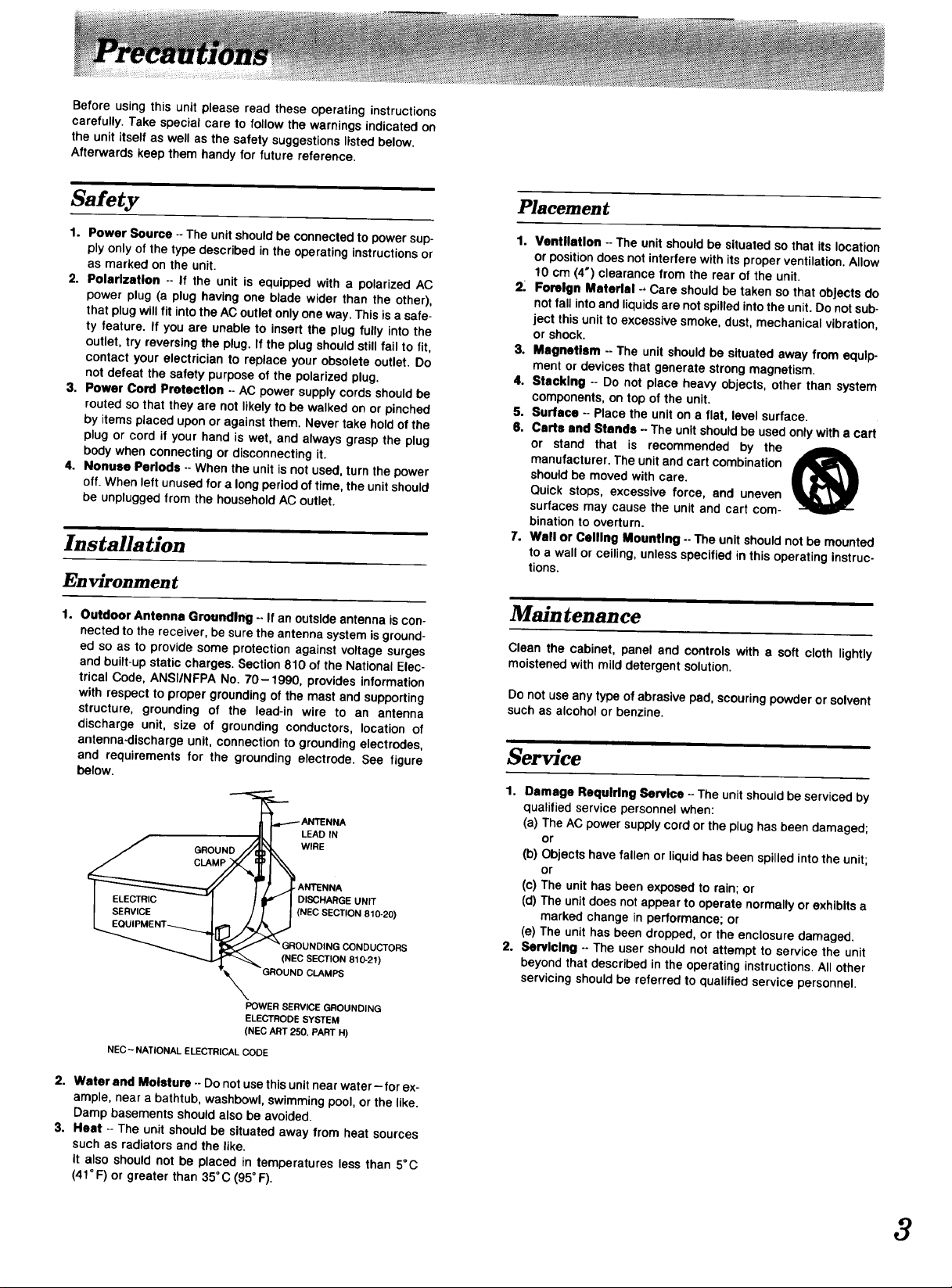
1. Outdoor Antenna Grounding -- If an outside antenna is con-
nected to the receiver, be sure the antenna system is ground-
ed so as to provide some protection against voltage surges
and built-up static charges. Section 810 of the National Elec-
trical Code, ANSI/NFPA No. 70-1990, provides information
with respect to proper grounding of the mast and supporting
structure, grounding of the lead-in wire to an antenna
discharge unit, size of grounding conductors, location of
antenna-discharge unit, connection to grounding electrodes,
and requirements for the grounding electrode. See figure
below.
LEAD IN
WIRE
ANTENNA
DISCHARGE UNIT
(NEC SECTION 810-20)
ORS
810-21)
Placement
1. Ventilation -- The unit should be situated so that its location
or position does not interfere with its proper ventilation. Allow
10 cm (4") clearance from the rear of the unit.
2. Foreign Material -, Care should be taken so that objects do
not fall into and liquids are not spilled into the unit. Do not sub-
ject this unit to excessive smoke, dust, mechanical vibration,
or shock.
3. Magnetism -- The unit should be situated away from equip-
ment or devices that generate strong magnetism,
4. Stacking -- Do not place heavy objects, other than system
components, on top of the unit.
5. Surface -- Place the unit on a flat, level surface.
6. Carts and Stands -- The unit should be used only with a cart
or stand that is recommended by the
manufacturer. The unit and cart combination
should be moved with care.
Quick stops, excessive force, and uneven
surfaces may cause the unit and cart com-
bination to overturn.
7. Wall or Ceiling Mounting -- The unit should not be mounted
to a wall or ceiling, unless specified in this operating instruc-
tions.
Maintenance
Clean the cabinet, panel and controls with a soft cloth lightly
moistened with mild detergent solution.
Donot use anytypeof abrasivepad,scouringpowderor solvent
suchas alcoholor benzine.
Service
1. Damage Requiring Service -- The unit should be serviced by
qualified service personnel when:
(a) The AC power supply cord or the plug has been damaged;
or
(b) Objects have fallen or liquid has been spilled into the unit;
or
(c) The unit has been exposed to rain; or
(d) The unit does not appear to operate normally or exhibits a
marked change in performance; or
(e) The unit has been dropped, or the enclosure damaged.
2. Servicing -- The user should not attempt to service the unit
beyond that described in the operating instructions. All other
servicing should be referred to qualified service personnel.
POWER SERVICE GROUNDING
ELECTRODE SYSTEM
(NEC ART 250, PART H)
NEC- NATIONAL ELECTRICAL CODE
2. Water and Moisture -- Do not use this unit near water-for ex-
ample, near a bathtub, washbowl, swimming pool, or the like.
Damp basements should also be avoided.
3. Heat -- The unit should be situated away from heat sources
such as radiators and the like.
It also should not be placed in temperatures less than 5°C
(41 °F)or greater than 35°C (95° F).
3
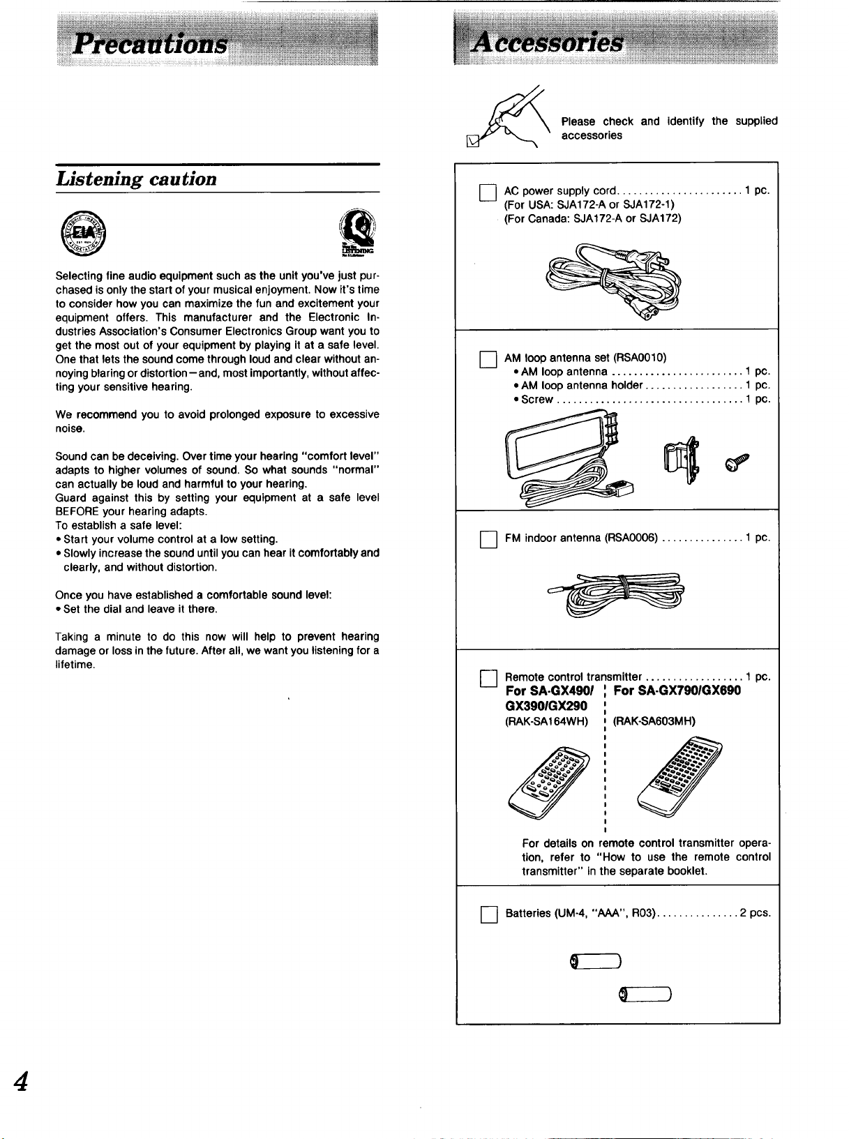
Please check and identify the supplied
accessories
Listening caution
@
Selecting fine audio equipment such as the unit you've just pur-
chased is only the start of your musical enjoyment. Now it's time
to consider how you can maximize the fun and excitement your
equipment offers. This manufacturer and the Electronic In-
dustries Association's Consumer Electronics Group want you to
get the most out of your equipment by playing it at a safe level.
One that lets the sound come through loud and clear without an-
noying blaring or distortion-and, most importantly, without affec-
ting your sensitive hearing.
We recommend you to avoid prolonged exposure to excessive
noise.
Sound can be deceiving. Over time your hearing "comfort level"
adapts to higher volumes of sound. So what sounds "normal"
can actually be loud and harmful to your hearing.
Guard against this by setting your equipment at a safe level
BEFORE your hearing adapts.
To establish a safe level:
• Start your volume control at a low setting.
• Slowly increase the sound until you can hear it comfortably and
clearly, and without distortion.
O AC supply cord 1 pc.
O AM loop antenna set (RSA0010)
power
(For USA: SJA172-A or SJA172-1)
(For Canada: SJA172-A or SJA172)
• AM loop antenna ........................ 1 pc.
• AM loop antenna holder .................. 1 pc.
• Screw .................................. 1 pc.
FM indoor antenna (RSAO006) ............... 1 pc.
Once you have established a comfortable sound level:
• Set the dial and leave it there.
Taking a minute to do this now will help to prevent hearing
damage or loss in the future. After all, we want you listening for a
lifetime.
Remotecontroltransmitter.................. 1 pc.
0
For SA.GX4901 For SA-GX7901GX690
GX3901GX290
(RAK-SA164WH) (RAK-SA603MH)
For detailson remote control transmitter opera-
tion, refer to "How to use the remote control
transmitter"inthe separatebooklet.
O Batteries (UM-4, "AAA", R03) ............... 2 pcs.
4
J
[ 13tTil_" f_IIl'}:f# IlYIlt:(,'_ll !
I DOLB¥ _ -MUTING
g g
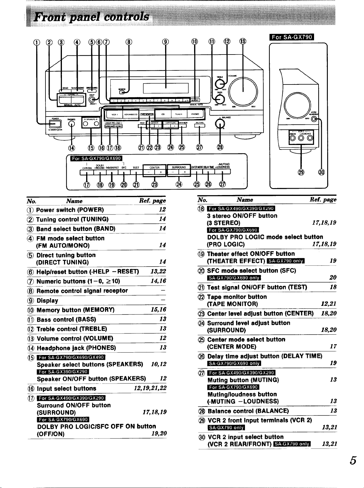
No. Name Re£. page
Power switch (POWER) 12
Tuning control (TUNING) 14
Band select button (BAND) 14
FM mode select button
(FM AUTOIMONO) 14
Direct tuning button
(DIRECT TUNING) 14
Helplreset button (.HELP -RESET) 13,22
Numeric buttons (1-0, >10) 14,16
Remote control signal receptor
Display
Memory button (MEMORY) 15,16
Bass control (BASS) 13
Treble control (TREBLE) 13
1_ Volume control (VOLUME) 12
Headphone jack (PHONES) 13
_ I _;Ti_'Y;][elt;f_l I//tlKq._IITIlt;q_ l_lll
Speaker select buttons (SPEAKERS) 10,12
11;1"i._',.N£etP:_IeTI4riK4PJ_I
Speaker ONIOFF button (SPEAKERS) 12
Input select buttons 12,19,21,22
_ i IISTdl.'__,I[I_;4_KIIIII}:qC_IITII};4_III
Surround ONIOFF button
(SURROUND) 17",18,19
lsTi." f__Nlel:4r4_10KO:(,_]
DOLBY PRO LOGICISFC OFF ON button
(OFFION) 19,20
]
No. Name
3 stereo ONIOFF button
(3 STEREO)
I'tTdl_l_]It_ilrd_II]IltN *'I_l
DOLBY PRO LOGIC mode select button
(PRO LOGIC) 17,18,19
Theater effect ONIOFF button
@
(THEATER EFFECT) I_
SFC mode select button (SFC)
®
__ O};f_DMtI.(.'_DI;]_ I
@
Test signal ONIOFF button (TEST)
®
Tape monitor button
(TAPE MONITOR)
Center level adjust button (CENTER)
Surround level adjust button
(SURROUND)
Center mode select button
@
(CENTER MODE)
Delay time adjust button (DELAY TIME)
I I'_'i€ f *_1[0:4_ KIOIIIt}:I{_I IT|t]}If_l_lll
@
Muting button (MUTING)
:l;1"m=f-_:#'_I01IO:( ,_]
Mutinglloudness button
(-MUTING - LOUDNESS)
Balance control (BALANCE)
VCR 2 front Input terminals (VCR 2)
VCR 2 input select button
(VCR 2 REARIFRONT)
Ref. page
1_1&19
19
20
18
12,21
18,20
18,20
17
19
13
13
13
13,21
13,21
5
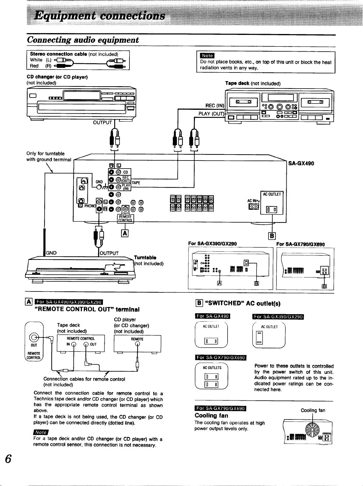
Connecting audio equipment
Stereo connection cable (not included) ]
White (L)
Red (R) • •
CD changer (or CD player)
(not included)
I
Do not place books, etc., on top ofthis unitor block the heat
radiationvents in anyway.
Tape deck (not included)
REO(,N)f',ro oooo',,I,Dil
Only for turntable
with ground terminal /
L. J
8
ONOL_ 0 _
"-; T
IGND
/-
] I ii)] Ib'1;llL'l_t I:1 IILtI_I{_J Irlll:f_i:{I l
q
"REMOTE CONTROL OUT" terminal
Tape deck
not included)
REMOTECONTROL
TPUTp:I
,/_" I(n°t included)
"_" "-" ,/
_3
@ CD
REC
IOUT)TAPE
/_ PLAY
(IN) :
@
@
@
_. Turntable
t___5
CD player
(or CD changer)
(not Included)
L_ -J
SA-GX490
ACOUTLET
BBBBB
For SA-GX3901GX290 For SA-GX7901GX690
_:: t'_ M " tmU ,=
l-_ "SWITCHED" AC outlet(s)
iD] I1" f!lltl_qCg lll{I}:f,_]
I REM0111:
Connection cables for remote control
(not included)
Connect the connection cable for remote control to a
Technics tape deck and/or CD changer (or CD player) which
has the appropriate remote control terminal as shown
above.
If a tape deck is not being used, the CD changer (or CD
player) can be connected directly (dotted line).
f
m
For a tape deck and/or CD changer(or CD player)with a
remotecontrolsensor,thisconnectionIsnot necessary.
i[o]m.-f±l[_'_Zvm:ImlAt't,_1.'1€1
Powerto these outlets Is controlled
by the power switch of this unit.
I ACOUTLETS I
i[,] I-'I-'1_;f$I IllL1;q ,_1_
Audioequipmentrated up to the in-
dicated power ratings can be con-
nected here.
Cooling fan
The cooling fan operates at high
power output levels only.
Cooling fan
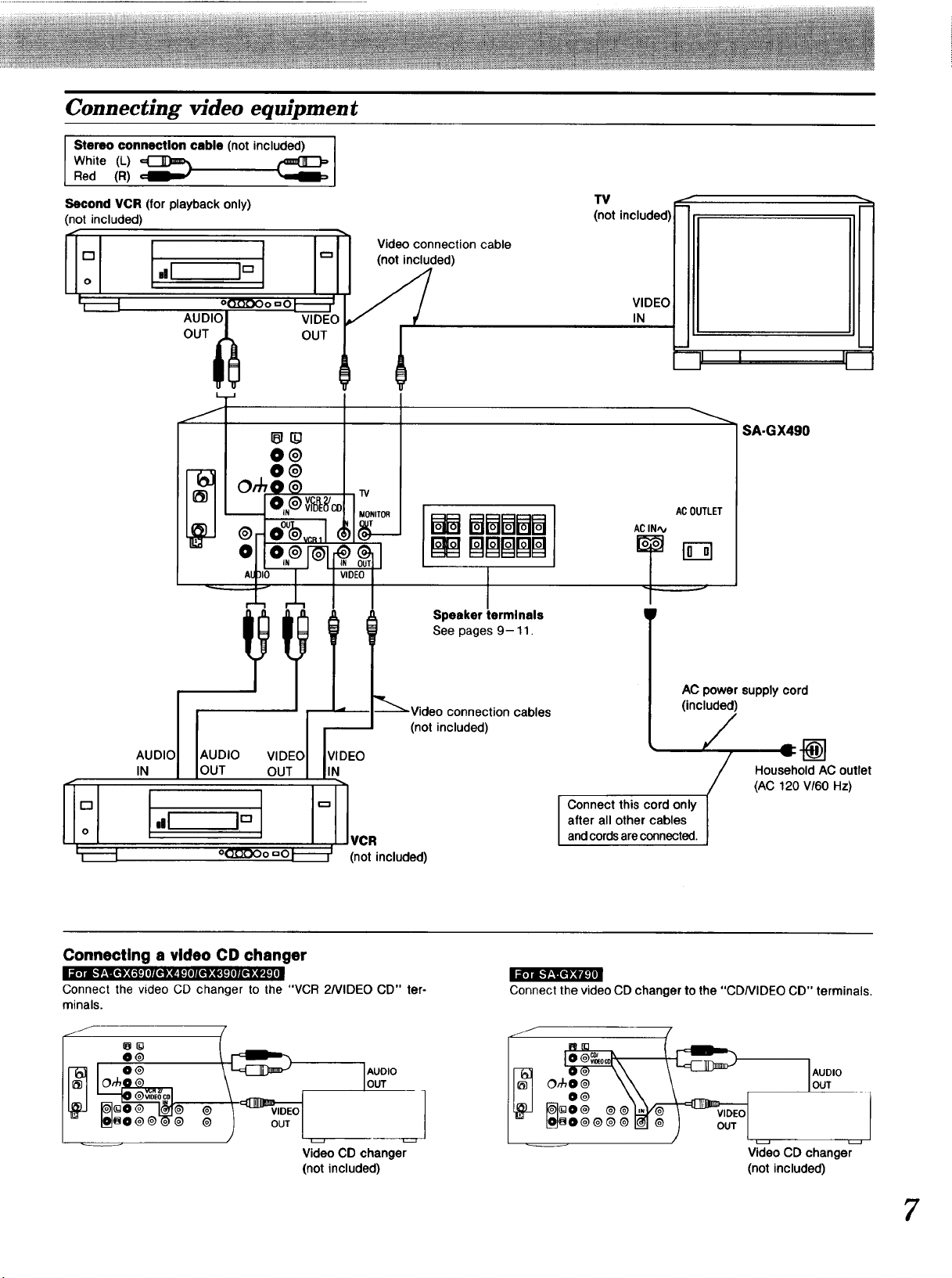
Connecting video equipment
Stereo connection cable (not included)
White (L)
Red (R)
Second VCR (for playback only)
(not included)
r"l _
o ,,I J'_
oQ.O.QOo=OI--_- 1
Video connection cable
(not included)
i i
TV
(not included)
VIDEO
IN
AUDI_J_ OUTVIDEO
IANUDIDI {AUDIO VIDEO
lOUT OUT
VIDEO
IN
rv
MONITOR
g__
+
Speaker terminals
See pages 9-11.
(not included)
cables
:-'-71 I I1_
----....
SA-GX490
ACOUTLET
ACIN_
AC power supply cord
(included)
I
/
Household AC outlet
(AC 120 V/60 Hz)
I.., ,°J v.
(not included)
Connecting a video CD changer
;!;1"i." f;_ll):(,_IIl{If;,e It Zll|tl);_ltlllJ[It;,f_]
Connect the video CD changer to the "VCR 2NIDEO CD" ter-
minals.
J
O@
O,_
@ @
I_mo @®-_-@ ®
OUT
Video CD changer
(not included)
AUDIO
OUT
I onnect this cord only (after all other cables
andcords are connected.
JI1';11[."]_[_
Connect the video CD changer to the "CD/VIDEO CD" terminals.
J
AUDIO
OUT
_oo@@@ I_ @
Video CD changer
(not included)
?

FM indoor antenna (i.clude_j
AM loop antenna (i.cl.de )
This antenna is normally sufficient for reception of FM broad-
casts.
FM Indoor antenna
(included)
_'", __.._Adhesive tape
(_) Pull off the plastic on the tip of
the antenna wire.
(_) Twist the wire and connect as
shown at the left.
__ _ _YJOBBfBB_
Twist
Attach to a wall (using a tape) facing Inthe direction of best recep-
tion.
For best reception sound quality
An FM outdoor antenna is recommended.
Disconnect the antenna if an FM outdoor antenna is installed.
FM outdoor antenna (rot ineJu_ed)
This antenna is normally sufficient for reception of AM broad-
casts.
(included)
[
/
AM ANT
AM LOOPANT
k..._.__.___.J
Install the AM loop antenna holder (Included) at the rear panel of
this unit and then attach the AM loop antenna to the AM loop
antenna holder (facing in the direction of best reception).
tab into
the hole and then
push the holder
of this unit
The outdoor antenna should be used when using the main unit in
mountainous areas or in spaces enclosed by reinforced concrete
where the FM indoor antenna (included) does not provide
satisfactory reception.
FM outdoor antenna
(not included)
75 £1coaxial
(notincluded)
(_ Remove a piece of the outer
vinyl insulator.
20 mm (25132")
(_) Twist the shield braid to
expose the core wire.
,,,.. Core wire
Shie_l braid 10/_mm(3/8")
_) Connect the shield braid and thq
core wire as shown at the left.
L. ...J
W
An outdoor antenna should be Installed by a qualified technician
only.
AM loop antenna holder
(included)
Pay attention to the following points when mounting the
antenna.
• Do not mount it horizontally (Doing so will impair reception).
• Do not mount it close to power cords, speaker wires or metal
surfaces (Doing so will result in noise).
• Do not mount it close to a tape deck. When the tape deck is be-
ing used, chirping or beeping sounds may result.
When mounting the antenna to a column, a wall
or rack
Mount it vertically.
loopantennaholder
(included)
Screw(included)
 Loading...