

Panasonic RJ-3600 Service Manual

oRDER NO.
RD
7704-1418
Servlce Manual
RJ-3600
REGEIVEI}JIl[.
E
$
grr
Radio
4O-CHANNEL
CITIZENS
BAND
TRANSCEIVER
^*"".4.e
,%
e
dh
TSPECIFICATIONS
Power
Source
Receiver
Section
Frequency
Range.
Sensitivity:
Selectivity:
Adjacent
Channel Rejection:
Audio
Distortion
at
1
kHz:
Cross Modulation
Rejection:
120
V
(60
Hz), AC
13.8 V,
DC
26.965
MHz to 27.405 MHz
Less
than
-6
dB
(0.5
mV)
for 10
dB
S/N
at
1 kHz,3O/"
modulation
Bandwidth
5
kHz min. for
6 dB
55 dB
Less than
10"/o at2W
Better than 45 dB
Transmitter
Section
Frequency
Range:
Power
Output
at 1S.g
V,
DC:
Modulation:
Emission (Class
D
Operation):
Spurious
Emission:
Frequency
Tolerance:
Speaker:
Dimensions:
Weight:
lmpedance:
26.965
MHz to 27.4A5
MHz
4
W max.
Less than 1 00ol"
6A3
-60
dB
+0.005%
4"
(10
cm) PM
Dynamic
Speaker
13+"(Wide)x
5*"(Hish)
x
8#"
(Deep)
(337x
133x220
mm)
10
lb. 6 oz.
(4.7
kg)
with
Microphone
MicrophoneJack
........7000
Speaker . ........8O
EXTSpeakerJack
.........8O
AntennaJack
.....50O
Panasonic
Company
Division
of
Matsushita
Electric
Corporation ol
America
One
Panasonrc
Way
Secalcus.
N
J 07094
specifications
are
subject
to
change without
notice
for further
improvement.
Matsushita
Electric
of Hawaii,
lnc.
Matsushita
Etectric
of
Canada
Ltd
32OWarakam,loRoad
Honoluru
Hawail96817
40Ronso^Or,veRerdareOnr
MgW
tRs
Panasonic.

IFEATURES
.
40 channels
.
L.E.D.
(Light
Emitting Diode)
Digital
Channel
Display
.
Preset
System
for all
zl0
channels
.
RF Gain Control
.
Two
llluminated Meters
(S/RF
Power and VU/MOD)
.
Squelch
Control
.
NB
(Noise
Blanking)/ANl
(Automatic
Noise
Limiter)
.
Antenna
Warning lndicator
ICONTROLS
AND
THEIR
FUNCTION
OPush-To-Talk
Switch
To transmit,
speak
into
the microphone while
pressing
this switch.
To receive, release it.
@Microphone
Speak
in a normal voice,
directly into the microphone.
Hold
the
microphone about an
inch
or two away from
your
mouth.
@Sfnf
Power Meter
This
meter has
two
functions:
When receiving, it indicates
the
relative strength of received signals in
'"S"
units.
"S1 "
indicates a
weak
or distant station; a
reading
of
"S9"
would indicate a
local
station. When transmitting, it indicates
the relative RF
power
output.
A reading in the
upper-portion of the meter indicates
proper
transmission
power.
@vu/MoD
Meter
lndicates the relative
strength of
your
voice into the microphone
during
transmission
(MOD),
and the relative strength
of the
speaker
power
output during reception
(VU).
While speaking
into
the
microphone,
adjust the voice strength
so
that the
pointer
stays
in
the
green
ranga,i.
@Antenna
Warning
(ANT
WARN) lndicator
This indicator
shows
antenna
matching
condition.
@On-Air
lndicator
Lights up
when
the Push-To-Talk
Switch
on the
Microphone
is in
the transmit
mode.
OOigitat
Channel Display Panel
lndicates which channel the
unit is turned to
for transmit
and
recieve. But, it
displays nothing when
the Preset Channel
Push-
switch
is
ON.
@Channel Selector
Selects any one
of
the
40
channels
for
transmit and
receive.
@Microphone
Socket
Plug the microphone into this
socket, and secure
the
plug
with the
captive screw-ring.
This
units
is
totally inoperable
if the
micro-
phone
is disconnected.
Note: Do not
us other microphones with dissimilar characteristics.
@
Preset
Channel
Pushswitch
I
When
pushing
this
pushswitch,
the indicator on
it lights up
and
channel
display disappears,
you
can
then communicate
on
any
channel
preset
with the
Preset Channel Selector,
regardless
of
the
Channel
Selector
position.
.
On-Air
lndicator
.
llluminated Preset
Channel Pushswitch
.
AC/DC Power
Operation
.
Positive, or Negative
Ground Operation
-
External
Speaker
Jack
.
Dynamic Microphone with
Push-To-Talk Switch
.
4" Diameter
Self-Contained Speaker
@Noise
Blanking
(NB)/Automatic
Noise Limiter
(ANL)
Push-
switch
Normally, leave the
switch in the
"OFF"
position.
Set
this
switch
in
the
"ON"
position
to reduce noise caused by
electric
motors, ignition,
lightning, etc. . . .
@On/Off
Switch andtolume Control
Turn the control clockwise to turn the set on
andto
adiust the
receiver's
sound
level.
@Squelch
Control
Use
to
cut background
noise
when no
signals
are being.
The
degree of sensitivity to incoming
signals
is
adjustable;
a clock-
wise
position provides
maximum squelch, but
in this
position,
it
may
also
cut out weak incoming
signals.
@RF
Gian
Control
Adjust the receiver
sensitivity for distortion{ree
reception.
Normally,
should be set in the MAX
position.
lf
received
signals
are
too
strong to understand,
slowly
rotate
this
control
counter-
clockwise until clear
sound
is obtained.
@Preset
ehannel Selector
Preselects any one of the 40 channels
for the Preset Channel
operation. Simply
turning the Preset Channel
Pushswitch on
adjusts,
the transceiver
to
a
preselected
channel
at any
time.
@Antenna
Socket
Any 50
O
antenna, designed
for
CB
applications,
may be con-
nected.
@External
Speaker Jack
When an external
8
O
speaker
is
connected,
the built-in
speaker
is
automatically disconnected.
@DC
Power Cord Connector
@DC
Fuse Holder
Suppliedwitha2Afuse.
@AC
Power
Cord
@AG
Fuse
Holder
Suppliedwitha2Afuse.
@ACIDC
Selctor Switch
@DC
Power
Cord
This unit is designed to operate on
1
3.8
V,
DC. Connect
this cord to
a
12 V
battery,
or other
12
V, DC
power
source.
For a vehicle or
boat
with a 24 V battery,
connect
the unit through a
24 V, DC to 12
V, DC converler, or
to a 12
V section ot a24V
electrical system.
(D(}(9
(,
r_,
\/
@o@
[Z nJ-eooo

ITO REMOVE
CABINET
COVER
1
. Remove
the
ten
(10)
screws
(nos.
1
,2,3,
4,5,
6,
7,
B, 9 &
10)
for
the
cabinet cover
as shown
in fig.
1.
2. Remove
the four (4)
screws
(nos.
1,
2,3. & 4) for
the cabinet
cover
as
shown
in fig.
2.
3. Remove the
four
(4)
screws (nos.
5, 6,
7,
& 8) for the bottom
cover
as
shown
in
fig.
2.
4.
Remove
the
cabinet
COvers.
5. Pull
out three
(3)
sockets, two
(2)
reads from
chassis and
fuse
holder.
6. To reassemble,
reverse
the
above
procedure.
ITO REMOVE
FRONT
PANEL
ASSEMBLY
1.
Remove
the
cabinet
cover.
(Refer
to
cabinet cover removal
instruction.)
2.
Remove
the four
(4)
control
knobs for
volume,
squelch,
RF
gain
and
selector,
as shown
in fig.
3.
3. Remove
the
five
(5)
screws
(nos.1
,2,3,
4 & 5)
forthe
front
panet,
as shown in fig.
3.
4. Remove
the six
(6)
screws
(nos.
1,
2, 3,
4.5
& 6)
for the
front
panel,
as shown in
fig. 4.
5. Remove
the
two
(2)
screws
(nos.
1 & 2)
for
the
front
panel
as
shown
in fig.
5.
6. Remove
the Mic
connector
and
speaker socket.
Remove
the
front
panel.
7. To reassemble, reverse
the above
procedure.
rTO REMOVE
ON
AIR
INDECATOR
1.
Remove
the front
cover
(Refer
to
front
cover removal
instruc-
tion.)
2. Bemove
the two
(2)
screws
(nos.
3 & 4) for
the
pC
board, as
shown
in fig.
5.
3. To
remove
ON
AIR
INDICATOR,
unsolder lead,
as shown
in
fig.
5.
4.
Pull
out
ON
AIR
|ND|CATOR
to
pC
board.
5. To
reassemble,
reverse
the
above
procedure
and read
the
following
note.
Note:
Mount
the
ON
AIR
IND|CATOR,
as shown in fig.
6.
Screw
No.3
Screw
No.4
Unsolder
lead
(Fig.
5)
,i
RECEIVEDJI.iL
2
9
1977
Screw
No.1
Screw
No.3
(CA'l
1 )
]
Screw
No.4
(CA11
)
Screw
No.5
(CA11
)
t"'"*
*'.u"
;"tj
l'. ;,:;itl==
q
ia
Screw
No.9
(CA
1 i )
(Fig.
1)
Screw
No.5
(xTN3+8C)
VOLUME
(Fig.
3)
Screw
No.10
(CA11
)
Screw
No.3
(CA11
r
Screw
No
Screw
No
Screw
No.5
(CA1t
r
Screw
No.3
(xrN3+1oC)
I
Screw
No.4
(XTN3+
8C)
(cAr
1
)
i
lselector
Knoo
RF GAIN Knoh
Screw
No.6
(CA11
Sorew
No.7
(CAt1
(Fis.
2)
Screw
No.'l
Screw
No.2
(xTN3+8Ct
(XTN3
l10c)
SQUELCH
Knob
Knob
Serew
No.1
Screw
No.3
Screw
No.2
Screw
No.4
(xTN3+8C)
(xTN3+8C)
Screw
No.6
(xTN3+1oc)
Screw
No.5
(
xrN3+
8C)
Screw
No.2
(CA'1
1)
Screw
No.B(C4191
|
Screw
No.4
cAelil
(XTN3+1
ON AIR INDICATOR
Short
(Fis.
a)
RJ-3600
g

lch
2ch
3ch 4ch 5ch 6ch
7ch
Ech
9ch
10ch
1l ch
l2ch 13ch
14ch 1 5ch 16ch 1 7ch 18ch 1 9ch a)ch
i1
-1
o o
()
o o
l
sr
-2
o
O
o o o
O
(_)
o
il
-3
o
O
o
o
()
st -4
o
il.5
31
-6
jr
-AI
31
-B
o
o o o o
o o o o o o
31
-C
o
o o o o o o
o o o
il
-E
o
il
-F
sl
-G
ir
-a
o O O
o o
() () ()
o o
s1
-b (
o
o o o o o o o o o
i]
-c
o o
(,)
()
o o o o o o o o o o o o
il
-d
o
o
() ()
o
o
o o
o
o o o
il
-e
o
o o
o
o
o
ll
.f
o o o
o
()
o o
31
-o
o o
() ()
TSWITCH
POSITIONS
FOR CHANNEL
IBLOCK
DIAGRAM
/26 065\
I t lurz
\zt
qoz)
x
O
:
ON,
No mark: OFF.
VU/[,400
METER
ANT
CONNECTOF
lvlETER
PROTECToR
LICHT
21 ch
22ch
23ch 24ch 25ch
26ch
27ch 28ch
29ch
30ch
31 ch 32ch 33ch 34ch
35ch
36ch 37ch 38ch 39ch
40ch
il
-1
o o o o
o
o o
o
o
)1 -2
c
o O o o
o
o
o
o
i1
-3
o o
o
o
o
o
o
O
o
;t
-4
o
o o
o
o o
o o
o o
o o
;1 -5
o
rJ
o
o o
i1 -6
o
o
()
o
;1-At
() ()
o
i1 -B
o o o o o o o
o
o o o
I-C
o
o o
o
o
O O o o o o
t1
-E
o o
O
o o o
n -F'
x-G
O o
o
o
o o o
il
-a
o
o o
o o o O o o
o o
o
,r
-b
o o
(_)
o o o o o
o o o o
o o o o
il
-c
o
o o o o o o o
o o o o o o
o o o
o
il
-d
o o
o o o
o o
it
-g
o o o o
il
-,
o o C) o
o o o o
i1
-q
o
o o
o O
o o
37
66-38.1
oluHz
BUFFER
2SC1359
DIRECT ONAL
COUPLER
2SC945
E
nu-sooo
(Fig.
7)
DC
13.8V
AC
12OV
TR
TR? TR3 TR. TRj
TR 6
28C1
35S
8S(40 2SCB20 2SC02B 2SC829 2SC828
AGC
RF AMP NB NB
BUFFER
2SC828
SOUELCB
Schematic
Diagram-Model
RJ-3(
TRr
TRm
rC
!
TRtr
2SC82S
25A564
[t,kPC566 2SC02S
lst
Mlx
SOUELCH
Mlc AMP 2nd MLX
2SC82S 2SC02S
2SC828
'''
iPz
[flr,,,p7-yypl-.^r,
Qacuxno
P*,.',Xg,-..
_
eli
_ .F%fi
u^91
ffffiI,-qi=
TRr
TR,
TR)
rRx
TRr TR{ TRI
TRr
rR,
rC?
TRrc TRr TRr rnu----7,----- -
-rc,_
2SC135S
2SC185s 2SC135S 2SC135g
2SCB29 zSCI359 2SA564 zSCl359
2SC1957
Al/llltl5l202L
zSCl359 2SCl909 2SC1359 2SC829
fiVlru P006lC RVlzPCTl
TX
MIX
VCO TX
LOCAL OSC RF AMP BUFFER MIX SWITCHING PRE DRIVER
ORIVER VOLTAGE
COMPARATOR BUFFER
LAST
STAGE AMP OSC BUFFER
,
AVR
{1 I
&
70 I
t0t74ilt5r2t6
t3t4t'1
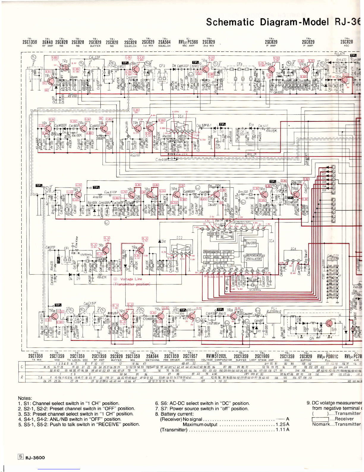
Notes:
'1
.
51
: Channel select
switch
in
"1
CH"
position.
2.
S2-1, S2-2:
Preset channel switch
in
"OFF"
position.
3.
53:
Preset channel select switch
in
"1
CH"
position.
4.
S4-1
,
S4-2:
ANL/NB switch
in
"OFF"
position.
5.
S5-1
,
S5-2:
Push to talk switch in
"RECEIVE" position.
n
3E
39LQ n
ljp
758596011
6. 56: AC-DC select switch in
"DC"
position.
7.
57:
Power
source switch
in
"off"
position.
8.
Battery current:
(Receiver)
Nosignal ...
....
-A
Maximumoutput .... .
.. . 1.25A
(Transmitter)
........
.....1"1
1A
_
lltr
jf
tts
lllttL-
9.
DC volatge
measuremer
from
negative terminal
r
(
).....Transmitter
f----l
....Receiver
Nomark....Trans mitter
E nu-gsoo
 Loading...