

Panasonic RF -4800 Operating Instructions Manual
•
n
Ions
MODEL NO. RF
-4800
FM/AM
10-BAND
COMMUNICATIONS
RECEIVER
Panasonic®
Read
these
instructions
completely
before
operating
this
set.

Your new Panasonic radio
receiver
RF-4800 was manufactured and assembled
under
exacting quality control standards.
The incorporation of the latest advances in radio design and the use
of
the most
modern components ensure outstanding performance with superb sensitivity and
tone quality.
Just a few minutes
of
your
time
spent reading carefully through these instructions
will
assure
your
obtaining optimum performance that
will
bring you continued
enjoyment
for
many years.
CONTENTS
LOCATION OF
CONTROLS...............................................................
3
POWER SUPPLY
...........................................................................
3
ANTENNAS
.......................................................................•...........•
4
CONTROLS AND FUNCTIONS
.........................................................
5
RECEIVER OPERATION
..................................................................
7
ABOUT SSB AND
CW
.....................................................................
8
ELECTROMAGNETIC-WAVE PROPAGATION
.......................................
9
PRECAUTIONS
..............................................................................
9
HELPFUL HINTS
...........................................................................
9
SPECIFICATIONS
..................................................
. ,
........................
10
The
serial
number
of
this
product may be found on the
back
of the unit.
You should note the
serial
number
of
this unit in the space provided and retain this
book as a permanent record
of
your
purchase to aid in identification in the event of
theft.
MODEL
NUMBER
:_
.....
R
....
F_--"48...,O.."O'--_
SERIAL
NUMBER:
______
_
WARNING:
TO PREVENT FIRE OR SHOCK HAZARD,
DO NOT EXPOSE THIS PRODUCT TO RAIN OR MOISTURE.
-1-
-2-

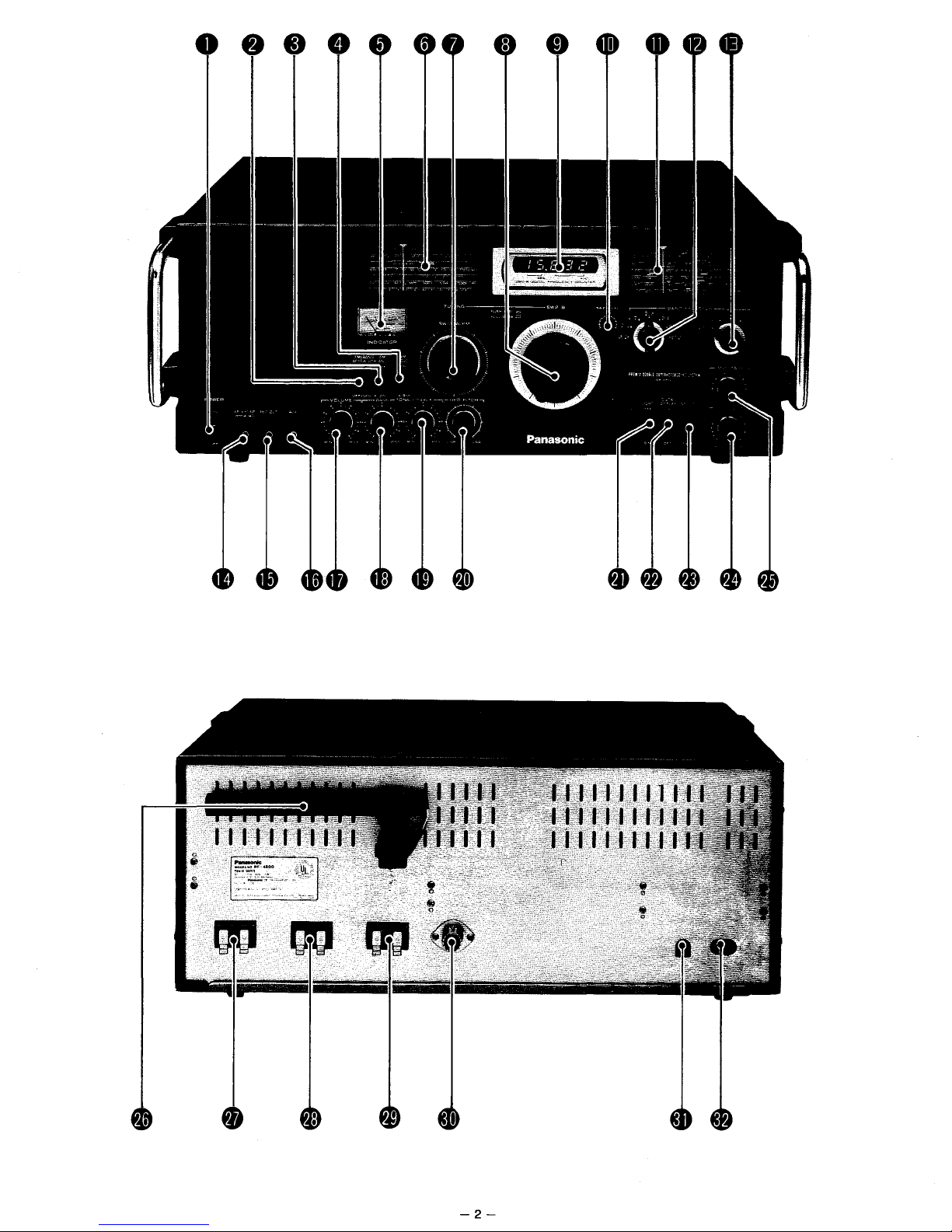
LOCATION OF CONTROLS
o Power Switch
8 FM AFC/Band Width Switch
8 AM ANL (Automatic Noise Limiter) Switch
e AM Mode Switch
o Tuning/Battery Indicator
CD
SW1/MW/FMTuning Scale
8 SW1/MW/FM Tuning Control
fa)
SW2-8 Tuning Control
o Digital Frequency Display
Gl>
SW2-8 Calibrater
~
SW2-8 Tuning Scale
~
SW2-8 Band Selector
G) Main Band Selector
~
Earphone/External Speaker Jack
~
Recording Output Jack
~
Auxiliary Input Jack
~
Volume Control
(9
Bass Control
~
Treble Control
~
BFO Pitch Control
~
Light Switch
@)
Display Switch
@)
Indicator Switch
~
AM
RF
Gain Control
~
Antenna Trimmer
~
MW Ferrite-Core Antenna
~
FM Antenna Terminals
@)
MW/SW1 Antenna Terminals
@)
SW2-8 Antenna Terminals
~
Coaxial-Cable Antenna Jack
~
DC Input Jack
~
AC
Input Jack
POWER SUPPLY
Battery Operation:
• Open
the
battery
compartment
covers
by
pushing
each latch
as
shown
in Fig.
1.
•
lrisert
8
"0"
size
(Panasonic
UM-1
or
equivalent)
batteries,
observing
the
correct
polarity,
as
shown
in Fig.
2.
Place
the
cloth
bands
under
the
batteries
to
facilitate
easy
removal.
•
Replace
the
compartment
covers.
Note:
Make
sure
the
DC
Input~
and AC
Input~
jacks
are
dis-
connected.
-3-
To check the battery condition:
Set
the
Indicator
Switch@) to
"BATT"
position
with
the
power
on.
The
Tuning/Battery
Indicator0
then
shows
the
battery
condition.
NORMAL
.
FULL
BATT
Fig. 3
When
the
indicator
reads
in
the
"0"
range
as
shown
above
the
batteries
are
good.
\ I
\ /
WEAK
\~
3 I
~d8
\ I I
\
BATJJ:RY
FULL
Fig. 4
When
the
indicator
reads
in
the
"x"
range
as
shown
above
replace
all
the
batteries
with
new
ones.

AC Power Operation:
•
Connect
the
included
AC
power
cord
to
the
AC
Input
Jack~
and
to
your
household
AC
electrical
outlet.
On
plugging
the
power
cord
into
the
AC
Input
Jack~,
opera-
tion
changes
from
battery
or
external
DC
power
to AC.
III
111111111111
III
III
111111111111
III
III
111111111111
III
()
I!l
to
AC IN
Fig. 5
Car/Boat Battery Operation:
•
Insert
the
plug of a
car
battery
adaptor
cord
into
the
DC
Input
JackG.
• Plug
the
other
end
into
the
cigarette
lighter
socket
in
your
car
or
boat.
•
This
automatically
disconnects
the
internal
batteries
and
the
receiver
operates
on
external
DC
power
only.
Note: For the
connection
of an
adaptor
cord,
follow
the
instruc-
tions
provided
with
it.
ANTENNAS
FM:
Connect
the
accessory
compact
FM
antenna
to
the
FM
Antenna
Terminals~,
then
extend
and
fix
the
antenna
on
the
wall
near
a
window
by
using
three
push-pins
or
adhesive
tape
as in Fig. 6.
If
the
FM
station
is
still
weak,
connect a suitable
outdoor
FM
antenna
(impedance:
75 ohms) to
replace
the
compact
antenna.
(For
installation,
follow
the
instructions
provided
with
the
antenna.)
MW:
The
rear
ferrite
core
antenna
will
assure
excellent
MW
recep-
tion
in
most
areas.
If
the
stations
are
distant
or
if
the
signals
are
very
weak,
connect a suitable
length of
the
accessory
antenna
wire
to
the
MW/SW1
Antenna
Terminals~,
and extend. (See
Fig. 7.)
=
~
11111111
111111
11111
II
IIIIIIIIIWIIIII
! I
:=J
~
To fix, use p
ush-pins
ape
or
adhesive
t
111111111111
III
Fig. 6
111111111111
III
111111111111
III
~
g
n
~~
~
~
"
I!le!l
How
to
Connect
Antenna
Wires
to
the
Terminals
Push
~
Terminal~~
Q
W/
~¥
i
Insert
wire
Push
Fig.
8
Te,minal_r
C)
r
C)
~
Iir.
Push
~ert
wire
-4-
SW:
External
antenna
and
ground
connections
are
required.
Figs.10-
13
give
examples
of
outdoor
SW
antenna
installation.
For
SW1
reception,
connect
the
antenna
and
ground
wires
to
the
MW/SW1
Antenna
Terminals~;
for
SW2-8
reception,
connect
them
to
the
SW2-8
Antenna
Terminals~.
The
Coaxial
Cable
Antenna
Jack€!)
for
SW2-8
reception
may
be used to
connect
an
SW
antenna
with
a
coaxial
cable.
With
this
kind
of
antenna,
solder
the
accessory
metal
plug
to
the
end of
the
cable
as in Fig.
9.
Erecting
the
antenna
as
high
and as
far
away
from
noise-generating
equip-
ment
and
high
tension
cables
as
possible
improves
the
reception.
To
avoid
danger
from
lightning,
it
is
strongly
advisable
to at-
tach a
safety
device
between
the
outdoor
antenna
and
the
receiver.
Fix a
knife
switch
(completed
connections
as
indicat-
ed in Fig. 14) as
near
to
the
receiver
entrance
of
the
antenna
lead
as
possible.
During
electrical
stroms,
short-circuit
the
antenna
to
ground
by
reversing
the
switch
to
the
ground
side.
jcore
.-Braided
Wire
Coaxial
Cable
-----Antenna
Wire
Antenna
Terminals
Plug
Cap
Fig. 7
Solder
core
Solder
braided
wire
Fig. 9
 Loading...