

Page 1
Operating Instructions
Projector Operations
DLP™ Based Projector
Model No.
PT-CW230EA
PT-CX200EA
Commercial Use
Thank you for purchasing this Panasonic Product.
J
Before operating this product, please read the instructions carefully, and save this manual
for future use.
For information on using the product via a network, refer to “Operating Instructions – Network
Operations”.
ENGLISH
PB2SC
Page 2
Read this rst!
Information
Important
WARNING:
WARNING: To prevent damage which may result in re or shock hazard, do not expose this appliance to rain
Machine Noise Information Ordinance 3. GSGV, January 18, 1991: The sound pressure level at the operator
position is equal or less than 70 dB (A) according to ISO 7779.
WARNING:
1. Remove the plug from the mains socket when this unit is not in use for a prolonged period of time.
2. To prevent electric shock, do not remove cover. No user serviceable parts inside. Refer servicing to
3. Do not remove the earthing pin on the mains plug. This apparatus is equipped with a three prong earthing
CAUTION:
TURN OFF THE UV LAMP BEFORE OPENING THE LAMP COVER.
THIS APPARATUS MUST BE EARTHED.
or moisture.
qualied service personnel.
type mains plug. This plug will only t an earthing-type mains socket. This is a safety feature. If you are
unable to insert the plug into the mains socket, contact an electrician. Do not defeat the purpose of the
earthing plug.
To assure continued compliance, follow the attached installation instructions, which includes
using the provided power cord and shielded interface cables when connecting to computer or
peripheral device. If you use serial port to connect PC for external control of projector, you must
use optional RS-232C serial interface cable with ferrite core. Any unauthorized changes or
modications to this equipment will void the user’s authority to operate.
WARNING:
WARNING:
WARNING:
TO REDUCE THE RISK OF FIRE OR ELECTRIC SHOCK, DO NOT EXPOSE THIS PRODUCT
TO RAIN OR MOISTURE.
RISK OF ELECTRIC SHOCK, DO NOT OPEN.
The lightning ash with arrowhead symbol, within an equilateral triangle, is intended to alert the
user to the presence of uninsulated “dangerous voltage” within the product’s enclosure that may
be of sufcient magnitude to constitute a risk of electric shock to persons.
The exclamation point within an equilateral triangle is intended to alert the user to the presence of
important operating and maintenance (servicing) instructions in the literature accompanying the
product.
2
- ENGLISH
Page 3
Read this rst!
13A250V
BS1363/A
HE-8
N
ASA
L
IMPORTANT: THE MOULDED PLUG (U.K. only)
FOR YOUR SAFETY, PLEASE READ THE FOLLOWING TEXT CAREFULLY.
This appliance is supplied with a moulded three pin mains plug for your safety and convenience. A 13 amp fuse
is tted in this plug. Should the fuse need to be replaced, please ensure that the replacement fuse has a rating
of13 amps and that it is approved by ASTA or BSI to BS1362.
Check for the ASTA mark or the BSI mark on the body of the fuse.
If the plug contains a removable fuse cover, you must ensure that it is retted when the fuse is replaced. If you
lose the fuse cover, the plug must not be used until a replacement cover is obtained. A replacement fuse cover
can be purchased from an Authorised Service Center.
If the tted moulded plug is unsuitable for the mains socket in your home, then the fuse should be
removed and the plug cut off and disposed of safely. There is a danger of severe electrical shock if the
cut off plug is inserted into any 13 amp socket.
If a new plug is to be tted, please observe the wiring code as shown below.
If in any doubt, please consult a qualied electrician.
Important
Information
WARNING:
IMPORTANT:
THIS APPLIANCE MUST BE EARTHED.
The wires in this mains lead are coloured in accordance with the following code:
Green - and - Yellow: Earth
Blue: Neutral
Brown: Live
As the colours of the wire in the mains lead of this appliance may not correspond with the coloured markings
identifying the terminals in your plug, proceed as follows.
The wire which is coloured GREEN - AND - YELLOW must be connected to the terminal in the
plug which is marked with the letter E or by the Earth symbol or coloured GREEN or GREEN -
AND - YELLOW.
The wire which is coloured BLUE must be connected to the terminal in the plug which is marked
with the letter N or coloured BLACK.
The wire which is coloured BROWN must be connected to the terminal in the plug which is
marked with the letter L or coloured RED.
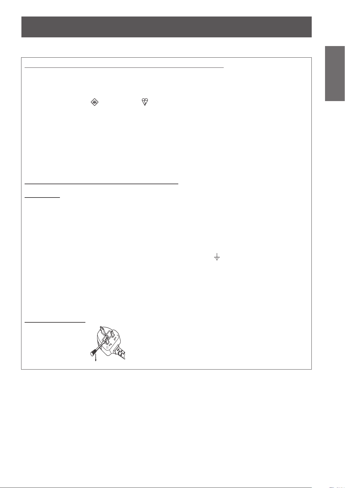
How to replace the fuse: Open the fuse compartment with a screwdriver and replace the fuse.
ENGLISH -
3
Page 4

Read this rst!
4
- ENGLISH
Important
Information
WARNING:
The wall outlet or the circuit breaker shall be installed near the equipment and shall be easily
accessible when problems occur. If the following problems occur, cut off the power supply
immediately.
Continued use of the projector in these conditions will result in re or electric shock.
During a thunderstorm, do not touch the projector or the cable.
Electric shocks can result.
Do not do anything that might damage the power cord or the power plug.
If the power cord is used while damaged, electric shocks, short-circuits or re will result.
Insert the power plug securely into the wall outlet.
If the plug is not inserted correctly, electric shocks or overheating will result.
Clean the power plug regularly to prevent it from becoming covered in dust.
Failure to observe this will cause a re.
Do not handle the power plug with wet hands.
Failure to observe this will result in electric shocks.
Do not overload the wall outlet.
If the power supply is overloaded (ex., by using too many adapters), overheating may occur and re will result.
POWER
If foreign objects or water get inside the projector, cut off the power supply.
z
If the projector is dropped or the cabinet is broken, cut off the power supply.
z
If you notice smoke, strange smells or noise coming from the projector, cut off the power supply.
z
Please contact an Authorized Service Center for repairs, and do not attempt to repair the projector yourself.
Do not damage the power cord, make any modications to it, place it near any hot objects, bend it
z
excessively, twist it, pull it, place heavy objects on top of it or wrap it into a bundle.
Ask an Authorized Service Center to carry out any repairs to the power cord that might be necessary.
Do not use anything other than the provided power cord.
z
Do not use the provided power cord for other electrical equipment.
z
Do not use plugs which are damaged or wall outlets which are coming loose from the wall.
z
If dust builds up on the power plug, the resulting humidity can damage the insulation.
z
If not using the projector for an extended period of time, pull the power plug out from the wall outlet.
z
Pull the power plug out from the wall outlet and wipe it with a dry cloth regularly.
ON USE/INSTALLATION
Do not place liquid containers on top of the projector.
If water spills onto the projector or gets inside it, re or electric shocks will result.
If any water gets inside the projector, contact an Authorized Service Center.
Do not place the projector on soft materials such as carpets or sponge mats.
Doing so will cause the projector to overheat, which can cause burns, re or damage to the projector.
Do not set up the projector in humid or dusty places or in places where the projector may come into
contact with oily smoke or steam, ex. a bathroom.
Using the projector under such conditions will result in re, electric shocks or components deterioration.
Components deterioration (such as ceiling mount brackets) may cause the projector which is mounted on the
ceiling to fall down.
Do not install this projector in a place which is not strong enough to take the full weight of the
projector or on top of a surface which is sloped or unstable.
Failure to observe this will cause projector to fall down or tip over the projector, and severe injury or damage
could result.
Do not place another projector or other heavy objects on top of the projector.
Failure to observe this will cause the projector to become unbalanced and fall, which could result in damage or
injury. The projector will be damaged or deformed.
Page 5

Read this rst!
ENGLISH -
5
Important
Information
WARNING:
Installation work (such as ceiling mount bracket) should only be carried out by a qualied technician.
If installation is not carried out and secured correctly it can cause injury or accidents, such as electric shocks.
Do not use anything other than an authorized ceiling mount bracket.
z
Be sure to use the wire provided with the projector mount base for ceiling mount as an extra safety
z
measure to prevent the projector from falling down. (Install in a different location to the ceiling mount
bracket).
Do not cover the air inlet port or the air outlet port.
Doing so will cause the projector to overheat, which can cause re or damage to the projector.
Do not place the projector in narrow, badly ventilated places.
z
Do not place the projector on cloth or papers, as these materials could be drawn into the air inlet port.
z
Do not place your hands or other objects close to the air outlet port.
Doing so will cause burns or damage your hands or other objects.
Heated air comes out of the air outlet port. Do not place your hands or face, or objects which cannot
z
withstand heat close to this port.
Do not look and place your skin into the lights emitted from the projection window while the projector
is being used.
Doing so can cause burns or loss of sight.
Strong light is emitted from the projector’s projection window. Do not look or place your hands directly into
z
this light.
Be especially careful not to let young children look into the projection window. In addition, turn off the power
z
and disconnect the power plug when you are away from the projector.
Do not insert any foreign objects into the projector.
Doing so will cause re or electric shocks.
Do not insert any metal objects or ammable objects into the projector or drop them onto the projector.
z
Never attempt to remodel or disassemble the projector.
High voltages can cause re or electric shocks.
For any inspection, adjustment and repair work, please contact an Authorized Service Center.
z
Do not allow metal objects, ammable objects, or liquids to enter inside of the projector. Do not allow
the projector to get wet.
Doing so may cause short circuits or overheating, and result in re, electric shock, or malfunction of the
projector.
Do not place containers of liquid or metal objects near the projector.
z
If liquid enters inside of the projector, consult your dealer.
z
Particular attention must be paid to children.
z
Use the ceiling mount bracket specied by Panasonic.
Defects in the ceiling mount bracket will result in falling accidents.
Attach the supplied safety cable to the ceiling mount bracket to prevent the projector from falling down.
z
Page 6

Read this rst!
6
- ENGLISH
Important
Information
WARNING:
Do not use or handle the batteries improperly, and refer to the following.
Failure to observe this will cause burns, batteries to leak, overheat, explode or catch re.
Do not allow children to reach the batteries (AAA/R03 or AAA/LR03 type).
If the battery uid leaks, do not touch it with bare hands, and take the following measures if necessary.
Do not disassemble the lamp unit.
If the lamp breaks, it could cause injury.
Lamp replacement
The lamp has high internal pressure. If improperly handled, an explosion and severe injury or accidents will
result.
Do not allow infants or pets to touch the remote control unit.
Do not use the supplied power cord with devices other than this projector.
Remove the depleted batteries from the remote control promptly.
ACCESSORIES
Do not use unspecied batteries.
z
Do not disassemble dry cell batteries.
z
Do not heat the batteries or place them into water or re.
z
Do not allow the + and
z
necklaces or hairpins.
Do not store batteries together with metallic objects.
z
Store the batteries in a plastic bag and keep them away from metallic objects.
z
Make sure the polarities (+ and
z
Do not use a new battery together with an old battery or mix different types of batteries.
z
Do not use batteries with the outer cover peeling away or removed.
z
Remove the empty batteries from the remote control at once.
z
Insulate the battery using tape or something similar before disposal.
z
The battery can cause personal injury if swallowed.
z
If swallowed, seek medical advice immediately.
z
Battery uid on your skin or clothing could result in skin inammation or injury.
z
Rinse with clean water and seek medical advice immediately.
Battery uid coming in contact with your eyes could result in loss of sight.
z
In this case, do not rub your eyes. Rinse with clean water and seek medical advice immediately.
The lamp can easily explode if struck against hard objects or dropped.
z
Before replacing the lamp, be sure to disconnect the power plug from the wall outlet.
z
Electric shocks or explosions can result if this is not done.
When replacing the lamp, turn the power off and allow the lamp it to cool for at least 1 hour before handling
z
it otherwise it can cause burns.
Keep the remote control unit out of the reach of infants and pets after using it.
z
Using the supplied power cord with devices other than this projector may cause short circuits or
z
overheating, and result in electric shock or re.
Leaving them in the unit may result in uid leakage, overheating, or explosion of the batteries.
z
-
terminals of the batteries to come into contact with metallic objects such as
-
) are correct when inserting the batteries.
Page 7
Read this rst!
ENGLISH -
7
Important
Information
CAUTION:
POWER
When disconnecting the power cord, be sure to hold the power plug and power connector.
If the power cord itself is pulled, the lead will become damaged, and re, short-circuits or serious electric
shocks will result.
When not using the projector for an extended period of time, disconnect the power plug from the wall
outlet and remove the batteries from the remote control.
Disconnect the power plug from the wall outlet before carrying out any cleaning and replacing the unit.
Electric shocks can result if this is not done.
ON USE/INSTALLATION
Do not put your weight on this projector.
You could fall or the projector could break, and injury will result.
Be especially careful not to let young children stand or sit on the projector.
z
Do not place the projector in extremely hot locations.
Doing so will cause the outer casing or internal components to deteriorate, or result in re.
Take particular care in locations exposed to direct sunlight or near stoves.
z
Always disconnect all cables before moving the projector.
Moving the projector with cables still attached can damage the cables, which will cause re or electric shocks
to occur.
Never plug headphones and earphones into AUDIO OUT jack.
Excessive sound pressure from earphones and headphones can cause hearing loss.
ACCESSORIES
Do not use the old lamp unit.
If used it could cause lamp explosion.
If the lamp has broken, ventilate the room immediately. Do not touch or bring your face close to the
broken pieces.
Failure to observe this will cause the user to absorb the gas which was released when the lamp broke and which
contains nearly the same amount of mercury as uorescent lamps, and the broken pieces will cause injury.
If you believe that you have absorbed the gas or that the gas has got into your eyes or mouth, seek
z
medical advice immediately.
Ask your dealer about replacing the lamp unit and check the inside of the projector.
z
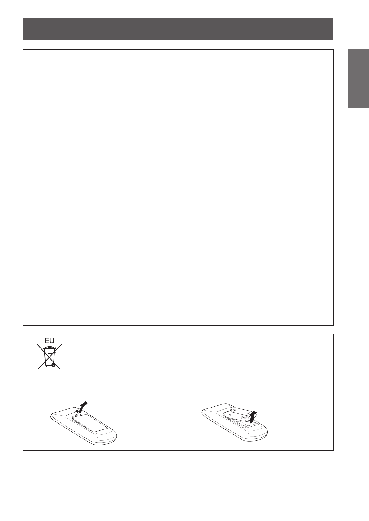
To remove the battery
Remote Control Battery
1. Press the guide and lift the cover. 2. Remove the batteries.
Page 8
Read this rst!
Information
Important
Trademarks
•
HDMI, the HDMI logo and High-Denition Multimedia Interface is a trademark or registered trademark of
HDMI Licensing LLC.
•
NVIDIA
Corporation in the United States and other countries.
•
Other names, company names or product names used in these operating instructions are the trademarks or
registered trademarks of their respective holders.
Please note that the operating instructions do not include the ® and TM symbols.
Illustrations in these operating instructions
Note that illustrations of the projector and screens may differ from the ones you actually see.•
Page references
•
In these instructions, references to pages are indicated as: (
Term
•
In these instructions, the “Wireless remote control unit” accessory is referred to as the “Remote control”.
®
, the NVIDIA® logo, and 3D VISION™ are registered trademarks and/or trademarks of NVIDIA
page 00).
Æ
8
- ENGLISH
Page 9
J
Features of the Projector
Auto Setup Function
This function enables Input search
and Auto PC adjustment by pressing
the <AUTO SETUP> button.
J
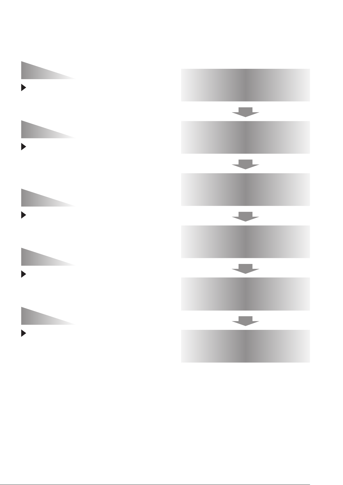
Quick steps
For details, see the corresponding pages.
1. Set up your projector.
(Æpage 21)
Direct Power Off Function
With the Direct Power Off function,
you can disconnect the power cord
from the wall outlet or turn off the
breaker even during projection.
Large Screen in Limited Space
Short focus lens allows you to
project large images from short
distance.
LAN Network Function
This function allows you to operate
and manage the projector via
network.
2. Connect with other devices.
(Æpage 25)
3. Connect the power cord.
(Æpage 26)
4. Power on.
(Æpage 28)
5. Select the input signal.
(Æpage 31)
3D Display Function
This projector is capable of
displaying 3D video with the Frame
Sequential Format, and you can
view the dynamic 3D contents by
wearing 3D glasses.
6. Adjust the image.
(Æpage 31)
ENGLISH -
9
Page 10

10
- ENGLISH
Important
Information
Preparation Getting Started Basic Operation Settings Maintenance Appendix
Contents
Be sure to read “Read this rst!”. ( pages 2 to 8)
Important Information
Read this rst! ........................................... 2
Contents ................................................... 10
Precautions for Use................................. 12
Preparation
About Your Projector .............................. 17
Using Remote control ............................. 20
Getting Started
Setting up ................................................. 21
Connections ............................................. 25
Basic Operation
Powering ON/OFF .................................... 26
Projecting ................................................. 31
Cautions when transporting .......................................... 12
Cautions when installing ............................................... 12
Security ........................................................................ 13
Disposal ........................................................................ 13
Cautions on use ........................................................... 14
Accessories .................................................................. 16
Optional accessories .................................................... 16
Remote control ............................................................. 17
Projector body .............................................................. 18
Control panel ............................................................... 19
Side terminals ............................................................... 19
Installing and Removing batteries ................................ 20
Setting Remote control ID numbers ............................. 20
Projection method ........................................................ 21
Parts for ceiling or wall mount (Optional) ..................... 21
Screen size and throw distance ................................... 22
Adjusting front adjustable feet ...................................... 24
Before connecting to the projector ............................... 25
Connecting example ..................................................... 25
Connecting the power cord .......................................... 26
ON(G)/STANDBY(R) indicator...................................... 27
Turning On the Projector .............................................. 28
Enter a PIN code .......................................................... 29
Turning Off the Projector .............................................. 30
Selecting the image ...................................................... 31
How to adjust the state of the image ............................ 31
For Viewing 3D Contents ............................................. 32
Basic operations by using the remote
control................................................... 33
Using the AUTO SETUP function ................................. 33
Switching the input signal ............................................. 33
Using the SCREEN button ........................................... 33
Using the KEYSTONE button ....................................... 34
Using the INFO. button ................................................. 34
Using the FREEZE function ......................................... 34
Using the AV MUTE function ........................................ 35
Using the P-TIMER button ........................................... 35
Using the LAMP button ................................................ 35
Using the D.ZOOM buttons .......................................... 35
Controlling the volume of the speaker .......................... 35
Using the IMAGE button ............................................... 35
Using the 3D button ...................................................... 36
Using the MUTE button ................................................ 36
Settings
Menu Navigation ...................................... 37
Navigating through the menu ....................................... 37
Main menu .................................................................... 38
Sub menu ..................................................................... 38
Input menu ............................................... 40
Computer 1: RGB/Component /RGB (Scart) ............... 40
Computer 2: RGB ......................................................... 40
HDMI ............................................................................ 41
Video ............................................................................ 41
S-video ......................................................................... 41
AUTO PC adjust ....................................... 42
AUTO PC adj. ............................................................... 42
Manual PC adjust ..................................... 43
Fine sync ...................................................................... 43
Total dots ...................................................................... 43
Horizontal ..................................................................... 43
Vertical .......................................................................... 43
Current mode ............................................................... 44
Clamp ........................................................................... 44
Reset ............................................................................ 44
Mode free ..................................................................... 44
Store ............................................................................. 44
Image select ............................................ 45
Dynamic ....................................................................... 45
Standard ....................................................................... 45
Real .............................................................................. 45
Cinema ......................................................................... 45
Image 1-4 ..................................................................... 45
Image adjust............................................. 46
Contrast ........................................................................ 46
Brightness .................................................................... 46
Page 11

ENGLISH -
11
Important
Information
PreparationGetting StartedBasic OperationSettingsMaintenanceAppendix
Contents
Color ............................................................................. 46
Tint .............................................................................. 46
Color temp. ................................................................... 46
Red .............................................................................. 47
Green ........................................................................... 47
Blue ............................................................................. 47
Sharpness .................................................................... 47
Gamma ......................................................................... 47
Noise reduction ............................................................ 47
Progressive .................................................................. 48
Reset ............................................................................ 48
Store ............................................................................. 48
Screen ...................................................... 49
Normal .......................................................................... 49
Full .............................................................................. 49
Wide(16:9) .................................................................... 49
Zoom ............................................................................ 49
True .............................................................................. 49
Natural wide
Custom ......................................................................... 49
Custom adj. .................................................................. 50
Digital zoom +............................................................... 50
Digital zoom - ............................................................... 50
Keystone ...................................................................... 50
Ceiling .......................................................................... 51
Rear .............................................................................. 51
Screen aspect (PT-CW230EA Only) ............................ 51
Colorboard .................................................................... 51
Reset ............................................................................ 51
(PT-CW230EA Only) ................................. 49
Sound ....................................................... 52
Lamp runtime ............................................................... 58
Filter counter ................................................................ 59
Factory default .............................................................. 59
Information ............................................... 60
Input Source Information Display ................................ 60
Maintenance
LAMP and WARNING Indicators ............ 61
Managing the indicated problems ................................ 61
Replacement ............................................ 62
Before replacing the unit .............................................. 62
Maintenance ................................................................. 62
Replacing the unit ......................................................... 62
Troubleshooting ...................................... 66
Appendix
Technical Information ............................. 68
Serial terminal .............................................................. 68
Other terminals ............................................................. 71
List of compatible signals ............................................. 73
Specications .......................................... 77
Dimensions ................................................................... 79
Ceiling mount bracket safeguards......... 79
Index ......................................................... 80
Volume ......................................................................... 52
Mute ............................................................................. 52
Setting ...................................................... 53
Language ..................................................................... 53
Menu position ............................................................... 53
Auto setup .................................................................... 53
3D setting ..................................................................... 54
Zoom ............................................................................ 54
Background .................................................................. 54
Display .......................................................................... 54
Logo ............................................................................. 55
HDMI setup .................................................................. 55
Terminal ........................................................................ 55
Standby mode .............................................................. 56
Power management ..................................................... 56
Direct on ....................................................................... 56
Closed caption .............................................................. 56
Lamp power .................................................................. 57
Remote control ............................................................. 57
Security ........................................................................ 57
Fan .............................................................................. 58
Fan control ................................................................... 58
Page 12

12
- ENGLISH
Important
Information
Precautions for Use
Cautions when transporting
z
z
Cautions when installing
J
z
J
z
z
z
J
This requires an optional ceiling mount bracket.
Model No.: ET-PKV100H (for high ceilings), ET-PKV100S (for low ceilings),
ET-PKC100B (Projector Mount Base), ET-PKC100W (Wall Mount Bracket).
When transporting the projector, hold it securely by its bottom and avoid excessive vibration and impacts.
Doing so may damage the internal parts and result in malfunctions.
Do not transport the projector with the adjustable feet extended. Doing so may damage the adjustable feet.
Do not set up the projector outdoors.
The projector is designed for indoor use only.
Do not use under the following conditions.
Places where vibration and impacts occur such as in a car or vehicle: Doing so may damage the internal parts
and result in malfunctions.
Near the exhaust of an air conditioner or near lights (studio lamps, etc.) where temperature changes greatly
(Operating environment Æpage 78): Doing so may shorten the life of the lamp or result in deformation of the
outer case and malfunctions.
Near high-voltage power lines or near motors: Doing so may interfere with the operation of the projector.
Be sure to ask authorized personnel or your supplier when mounting the
product to a ceiling or wall.
J
When using the projector in the elevation of below 1 000 m, make sure
[Fan control] is set to [Off].
Failure to do so may shorten the life of the internal parts and result in malfunctions.
J
When using the projector in the elevation of above 1 000 m and below
2 000 m, make sure [Fan control] is set to [On 1].
Failure to do so may shorten the life of the internal parts and result in malfunctions.
J
When using the projector in the elevation of above 2 000 m and below
2 700 m, make sure [Fan control] is set to [On 2].
Failure to do so may shorten the life of the internal parts and result in malfunctions.
J
Do not install the projector at elevations of 2 700 m (8 858 ft) or higher
above sea level.
Failure to do so may shorten the life of the internal parts and result in malfunctions.
Page 13
Precautions for Use
ENGLISH -
13
Important
Information
J
1.5' (50 cm)
3' (1 m)
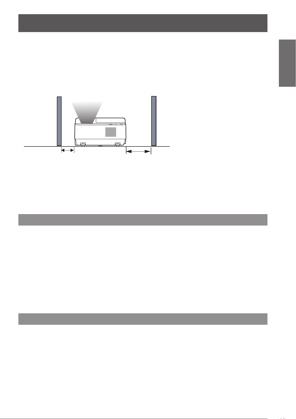
Cautions when setting the projectors
Do not stack the projectors.
z
Do not block the ventilation ports (intake and exhaust) of the projector.
z
Avoid heating and cooling air from the air conditioning system directly blow to the ventilation ports (intake and
z
exhaust) of the projector.
Do not place the projector in an enclosed space.
z
If you need to place the projector in an enclosed space, additional air conditioning and ventilation system
must be equipped. When ventilation is insufcient, remaining heat may trigger the protection circuit of the
projector.
Security
J
Take safety measures against following incidents.
Personal information being leaked via this product.
z
Unauthorized operation of this product by a malicious third party.
z
Interfering or stopping of this product by a malicious third party.
z
J
Security instruction (
Make your password as difcult to guess as possible.
z
Change your password periodically.
z
Panasonic or its afliate company never inquires a password directly to a customer. Do not tell your password
z
in case you receive such an inquiry.
The connecting network must be secured by rewall or others.
z
Set a password and restrict the users who can log in.
z
page 57 )
Æ
Disposal
When disposing of the product, ask your local authority or dealer about the correct methods of disposal.
The lamp contains mercury. When disposing of the used lamp unit, ask your nearest local authorities or dealer
about proper disposal of the unit.
Dispose of used batteries according to the instructions or your local disposal rule or guidelines.
Page 14

Precautions for Use
14
- ENGLISH
Important
Information
Cautions on use
J
z
z
z
J
If the surface of the projection window becomes dirty from ngerprints or anything else, this will be magnied and
projected onto the screen.
J
z
z
J
Operating the projector in an environment with high temperature or heavy exposure to dust or tobacco smoke will
reduce the service life of the optical components and may necessitate their replacement within less than one year
of use. For details, consult your dealer.
In order to get the picture quality
Draw curtains or blinds over windows and turn off any lights near the screen to prevent outside light or light
from indoor lamps from shining onto the screen.
Depending on where the projector is used, heated air from an exhaust port or warm or cold air from an air
conditioner can cause a shimmering effect on screen.
Avoid use in locations where exhaust or streams of air from projector, other devices and air conditioners ow
between the projector and the screen.
The lens of projector is affected by the heat from the luminous source. Because of this, the focusing may not
be stable right after the power is turned on. Focusing is stabled after projecting image for 30 minutes and
longer.
Do not touch the surface of the projection window with your bare hand.
DLP chips
The DLP chips are precision-made. Note that in rare cases, pixels of high precision could be missing or
always lit, but this is not a malfunction.
Directing a high power laser beam onto the projection window surface can damage the DMD element.
Optical components
J
Lamp
The luminous source of the projector is a mercury lamp with high internal pressure.
A high pressure mercury lamp has following characteristics.
The brightness of the lamp will decrease by duration of usage.
z
The lamp may burst with sound or shorten life by shock or chipping.
z
The life of the lamp varies greatly depending on individual specicities and usage conditions. In particular,
z
continuous use over 22 hours and frequent on/off switching of the power greatly deteriorate the lamp and
affect the lamp life.
In rare cases, the lamp burst shortly after the projection.
z
The risk of bursting increases when the lamp is used beyond its replacement cycle. Make sure to replace the
z
lamp unit consistently. (“When to replace the lamp unit” (Æ page 64))
If the lamp bursts, gas contained inside of the lamp is released in a form of smoke.
z
It is recommended to store replacement lamps for contingency.
z
It is recommended to have authorized engineer or your dealer replace the lamp unit.
z
J
Viewing 3D pictures
Caution for properly viewing 3D pictures:
The optimum 3D viewing distance from the screen is about 3 m or more and your eyes should be level with
z
the screen.
Viewing 3D images for an extended period of time or viewing them from an oblique angle can cause eye
z
strain.
Take breaks when viewing 3D images for an extended period of time. As this may cause eye fatigue.
z
Some image sources can cause pseudoscopic image problem. Check the 3D settings to get the 3D effect.
z
If the right-eye image and left-eye image are switched, you may not get the 3D effect, resulting in eye strain
z
or nausea.
There are differences in 3D visual perception between individuals.
z
If you get double vision or don’t get the 3D effect, discontinue using the projector.
z
If you experience fatigue or nausea, stop using the projector.
z
After viewing the rotating, swinging, or jumping 3D images, you may experience 3D motion sickness.
z
If you experience such symptom, immediately stop viewing the 3D images and take a break until the symptom
z
has subsided.
Page 15

Precautions for Use
ENGLISH -
15
Important
Information
If you view 3D images in bright ambient light environment, you may not able to see them clearly. Or if you use
z
the 3D glasses in a room which uorescent lighting (50Hz), ickering may occur. If these happen, change the
room lighting condition by making the room dark or turning off the light.
Restrictions on viewing 3D images:
Children who are six year of age or younger should not view 3D images.
z
Parents should accompany and monitor their children as children cannot properly express discomfort with 3D
z
image viewing.
Photosensitive patients, patients with heart disease, pregnant women, elderly people, and people with serious
z
illness and/or with a history of epilepsy should not view 3D images.
We advise that you should refrain from viewing 3D images if you are in bad physical condition.
z
We do not recommend viewing 3D images if you need sleep or have been drinking alcohol.
z
Pursuant to at the directive 2004/108/EC, article 9(2)
Panasonic Testing Centre
Panasonic Service Europe, a division of Panasonic Marketing Europe GmbH
Winsbergring 15, 22525 Hamburg, F.R. Germany
Page 16
Precautions for Use
Information
Important
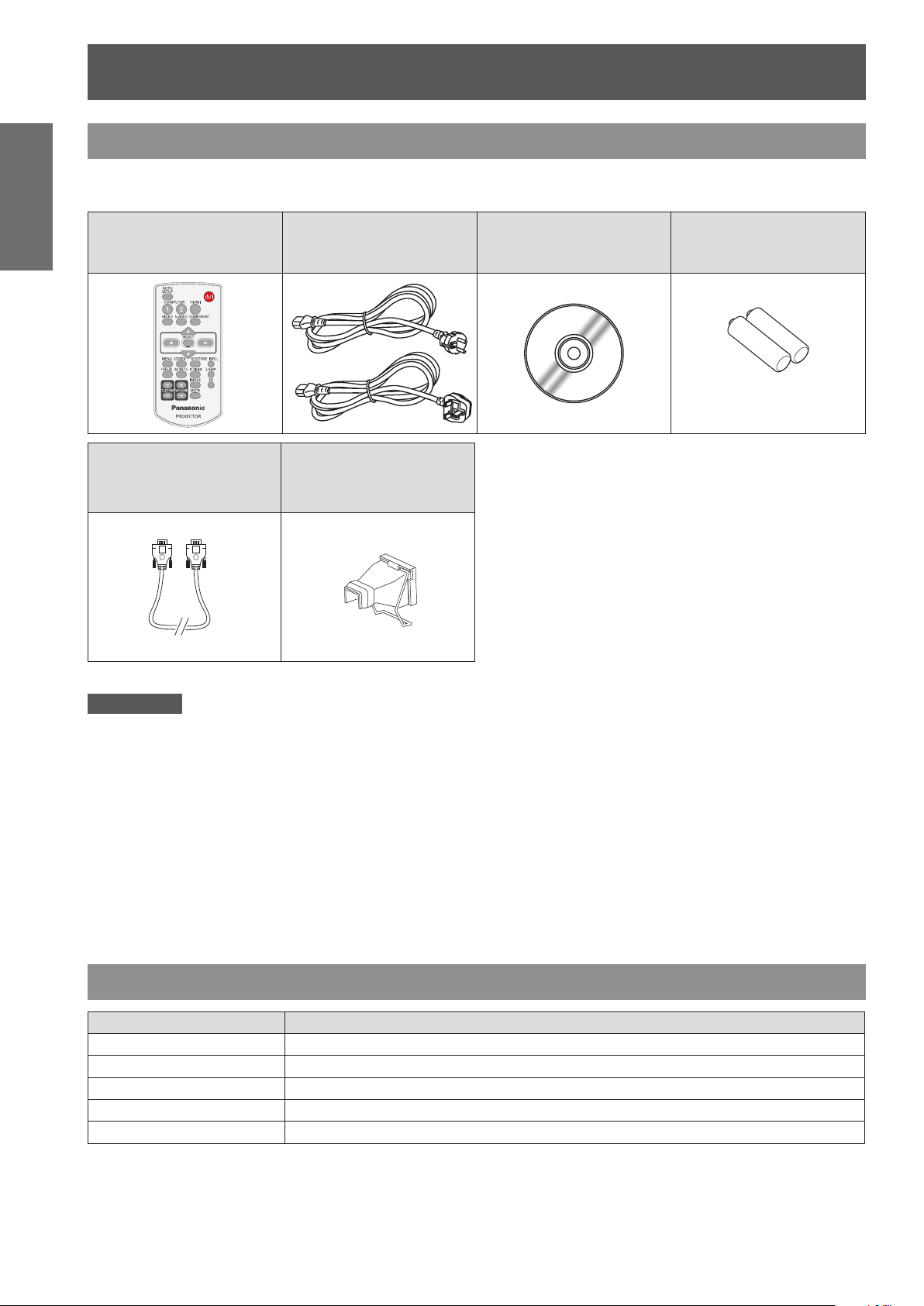
Accessories
Make sure the following accessories are provided with your projector. Numbers in the brackets ( ) show the
number of accessories.
Remote control unit (x1)
(6451054586)
RGB signal cable (x1)
(6103580425)
Power cord (x1)
(6103597768)
(6103597775)
AC power cord holder
(x1) (6103573700)
(6103595221)
CD-ROM (x1)
(6103615875)
Batteries (AAA/R03 or
AAA/LR03 type) (x2)
(for remote control unit)
Attention
After unpacking the projector, discard the power cord cap and packaging material properly.
z
For lost accessories, consult your dealer.
z
The part numbers of accessories and separately sold components are subject to change without notice.
z
Store small parts in an appropriate manner, and keep them away from young children.
z
J
Contents of the supplied
The contents of the supplied CD-ROM are as follow. [: Instructions/List (PDF)]
Operating Instructions – Projector Operations
Operating Instructions – Network Operations
CD-ROM
Optional accessories
Options Model No.
Ceiling Mount Bracket
Projector Mount Base
Wall Mount Bracket
Replacement Lamp Unit
Replacement Filter Unit
ET-PKV100H (for high ceilings), ET-PKV100S (for low ceilings)
ET-PKC100B
ET-PKC100W
ET-LAC100
ET-RFC100
16
- ENGLISH
Page 17

About Your Projector
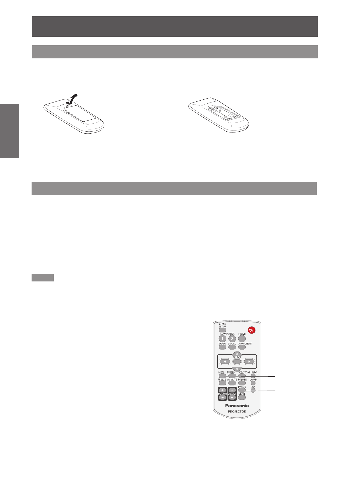
Remote control
(18)
(1)
(2)
(3)
(4)
(5)
(6)
(7)
(8)
(9)
(10)
(11)
(12)
(13)
(14)
(15)
(16)
(17)
(10) < > Button
Turn the projector on or off. (Æpage 28)
(11) <KEYSTONE> Button
Correct keystone distortion. (Æpage 34)
(12) <INFO.> Button
Operate the information function. (Æpage 34)
(13) <LAMP> Button
Select a lamp mode. (Æpage 35)
(14) <P-TIMER> Button
Operate the P-timer function. (Æpage 35)
(15) <3D> Button
Operate the 3D function. (Æpage 36)
(16) <IMAGE> Button
Select the image mode. (Æpage 35)
(17) <MUTE> Button
Mute the sound. (Æpage 36)
(18) Remote control signal emitter
Attention
Do not drop the remote control.
z
Avoid contact with liquids.
z
Do not attempt to modify or disassemble the remote
z
control.
Preparation
(1) <AUTO SETUP> Button
Execute the setting of Auto setup in the setting
menu. (Æpage 53)
(2) Input Selection Buttons: <COMPUTER 1>,
<COMPUTER 2>, <HDMI>, <VIDEO>,
<S-VIDEO>, <COMPONENT>.
These buttons are used to select the input signal.
(Æpage 33)
(3) ▲▼◄► Buttons, <SELECT> Button
Navigate the MENU display. (Æpage 37)
(4) <SCREEN> Button
Select a screen mode. (Æpage 49)
(5) <MENU> Button
Open or close the On-Screen Menu. (Æpage 37)
(6) <FREEZE> Button
Pause the projected image and sound tentatively.
(Æpage 34)
(7) <AV MUTE> Button
Temporarily turn off the image on the screen.
(Æpage 35)
(8) <D.ZOOM +/-> Buttons
Zoom in and out the images.(Æpage 33)
(9) <VOLUME +/-> Buttons
Adjust the volume of the speaker. (Æpage 35)
Note
If there are any obstacles between the remote control
z
and the remote control signal receptor, the remote control
may not operate correctly.
You can operate the projector by reecting the remote
z
control signal on the screen. The operating range may
differ due to the loss of light caused by the properties of
the screen.
When the remote control signal receptor is lit with a
z
uorescent light or other strong light source, the projector
may become inoperative. Set the projector as far from
the luminous source as possible.
Point the remote control toward the projector (remote
z
control signal receptor) when pressing the buttons. See
the below gures indicating Maximum operating range for
the remote control.
11.5’
(3.5 m)
16.4’
(5 m)
16.4’
(5 m)
ENGLISH -
17
Page 18
About Your Projector
18
- ENGLISH
Preparation
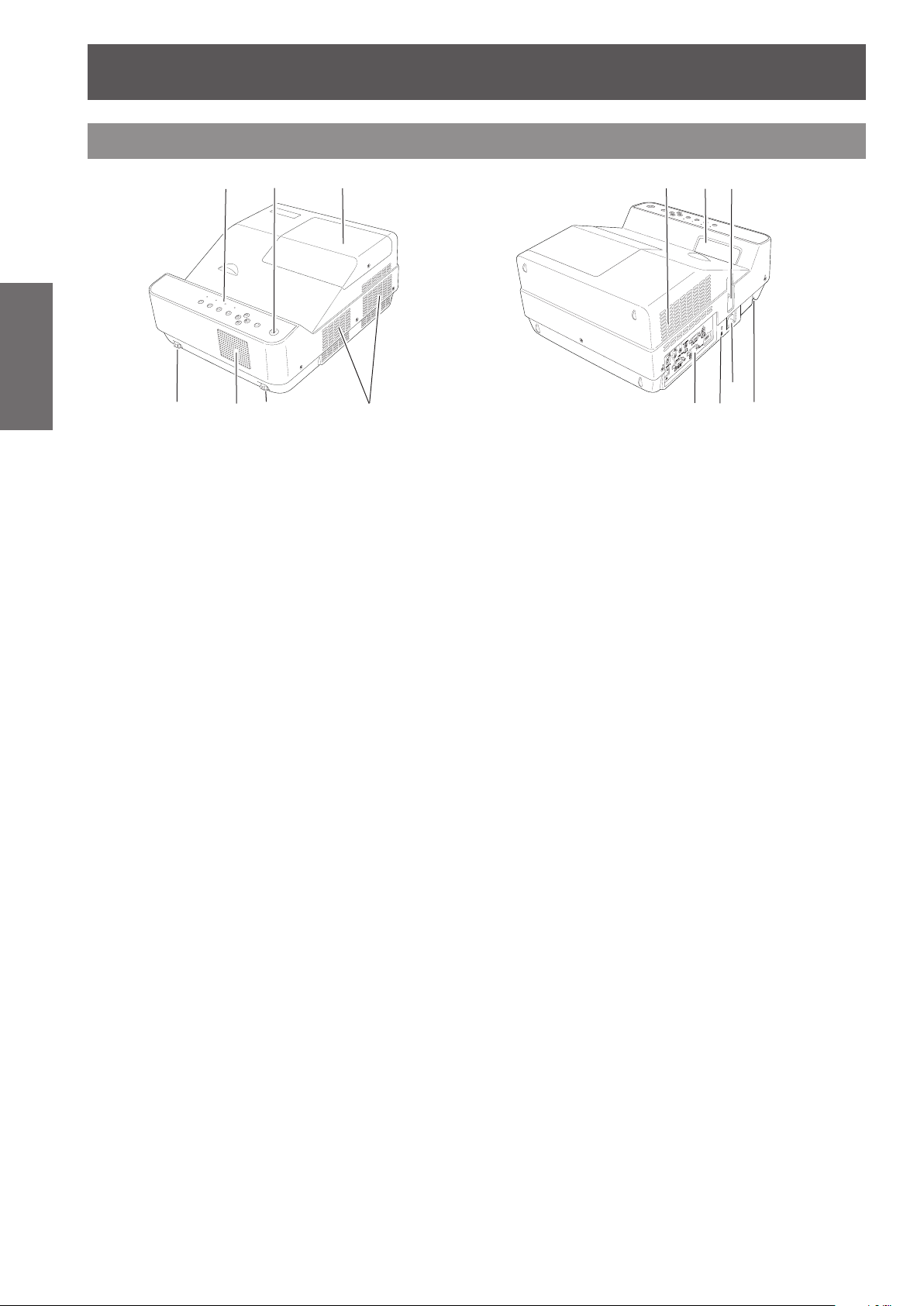
Projector body
(1) Control Panel and Indicators
(2) Remote control signal receptor
(3) Lamp cover (Lamp and Air Filter)
(4) Adjustable feet
(5) Speaker
(6) Air exhaust port
Hot air is exhausted from the air exhaust port. Do
(7) Air intake port
(8) Projection Window
(9) Focus Lever
(10) Terminals and Connectors
(1)
(4)
The lamp unit and lter unit are
Adjust the projection angle.
not put heat-sensitive objects near this side.
Adjust the focus.
(2) (3)
(4)
(5)
(6)
(Æpage 19)
(Æpage 65)
located inside.
(Æpage 19)
(7) (8)
(10)
(12)
(11)
(9)
(13)
WARNING:
J
Keep your hands and other objects
away from the air exhaust port.
z
Keep your hand and face away.
z
Do not insert your nger.
z
Keep heat-sensitive articles away.
Heated air from the air exhaust port can cause burns
or external damage.
(11) Kensington Security Slot
This slot is for a Kensington lock used to deter
theft of the projector.
Kensington is a registered trademark of ACCO
*
Brands Corporation.
(12) AC IN
(13) Security Bar
Page 19
About Your Projector
ENGLISH -
19
Preparation
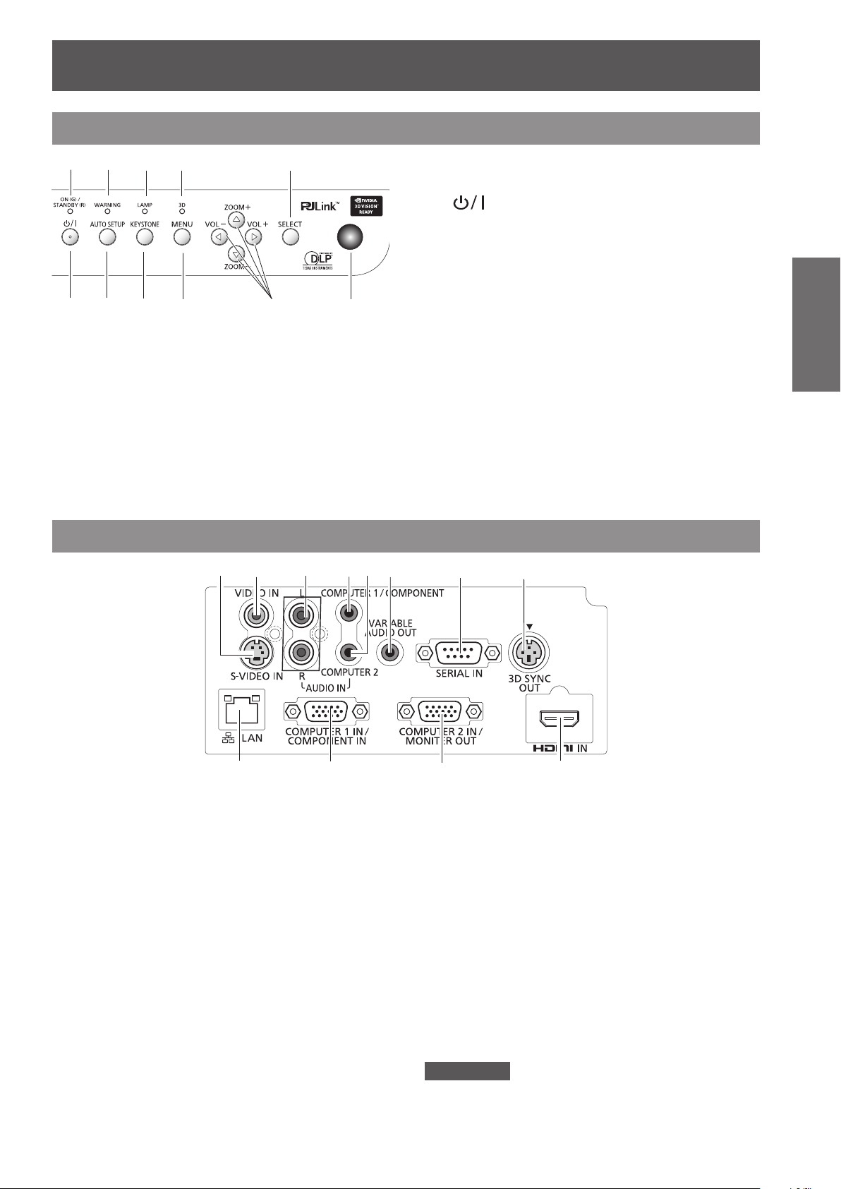
Control panel
(1) (2) (3) (4) (5)
(6) (7)
(1) <ON(G)/STANDBY(R)> indicator
Indicate the power status.
(2) <WARNING> indicator
Indicate the abnormal conditions of the projector.
(3) <LAMP> indicator
Light yellow when the projection lamp reaches its
end of life.
(4) <3D> indicator
Turn blue when the projector is in 3D mode.
(Æpage 32)
(8)
(9)
(10) (11)
Side terminals
(1)
(2)
(3) (4) (5)
(5) <SELECT> button
Execute the selected item.
(6) < > button
Turn the projector on/off.
(7) <AUTO SETUP> button
Execute the setting of Auto setup in the setting
menu. (Æpage 33)
(8) <KEYSTONE> button
Correct keystone distortion. (Æpage 34)
(9) <MENU> button
Displays the MENU screen. (Æpage 37)
(10) ▲▼(ZOOM -/+)/◄► (VOL -/+) buttons
Navigate the MENU screen.
Adjust the volume level (with <VOL -/+> buttons).
(Æpage 35)
(11) Remote control signal receptor
The protruding shape allows wide-angle remote
control signal reception.
(6)
(7)
(8)
(9) (10)
(1) S-VIDEO IN
Connect to S-VIDEO output signals.
(2) VIDEO IN
Connect to VIDEO output signals.
(3) AUDIO IN
Connect to the audio output signals.
AUDIO IN has right and left (L and R) terminals.
(4) COMPUTER 1/COMPONENT AUDIO IN
Connect the audio input signals.
(5) COMPUTER 2 AUDIO IN
Connect to the audio input signals.
(6) AUDIO OUT (VARIABLE)
Output the audio signals input to the projector.
(7) SERIAL IN
Connect to a computer via an RS-232C cable.
(11)
(8) 3D SYNC OUT
Connect a 3D sync. signal cable for an IR wireless
emitter to this jack.
(9) LAN
Connect to a LAN cable for network connection.
(10) COMPUTER 1 IN/ COMPONENT IN
Connect to COMPUTER 1 IN/ COMPONENT IN
input signals.
(11) COMPUTER 2 IN/ MONITOR OUT
Connect to COMPUTER 2 IN/ MONITOR OUT
input signals or outputs the analog RGB signals
input the projector.
(12) HDMI IN
Connect to HDMI input signals.
Attention
When a LAN cable is directly connected to the projector,
z
the network connection must be made indoors.
(12)
Page 20
Using Remote control
Installing and Removing batteries
Open the cover1 ) Install batteries and close the cover2 )
Preparation
z
Remove the batteries in the reverse order of installation.
Setting Remote control ID numbers
(Insert the – side rst.)
When you use the system with multiple projectors, you can operate each projector individually using single
remote control, if unique ID number is assigned to each projector.
After setting the ID number of the projector, set the same ID number to the remote control.
There are 2 different ID codes (Code 1 and Code 2), the initial ID number is [Code 1].
J
Setting the ID number
Press and hold both the MENU and IMAGE buttons together for 5 seconds or more. After changing the
code, make sure the remote control operates properly.
Note
For details, please refer to the [Remote control] of the [Setting] menu. (
z
z
This remote control is only for PT-CW230EA and PT-CX200EA. You cannot operate the other Panasonic projectors by
using this remote control.
page 57)
Æ
20
- ENGLISH
MENU button
IMAGE button
Page 21
Setting up
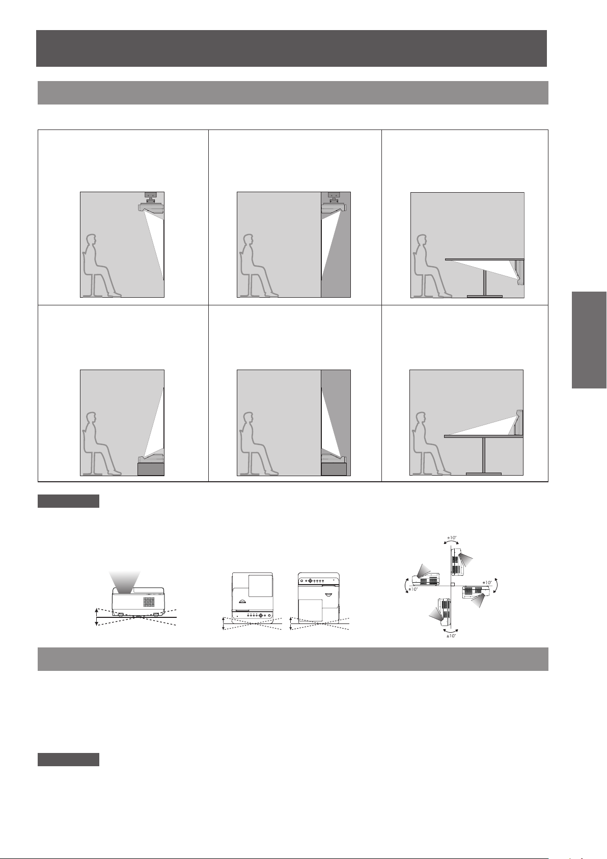
5˚
5˚
5˚
5˚
10˚
10˚
Projection method
You can use the projector with any of the following 6 projection methods. To set the desired method in the projector.
Mounting on the ceiling
J
and projecting forward
J
Setting on a desk/oor
and projecting from
forward
J
Mounting on the ceiling
and projecting from rear
(Using translucent screen)
Setting on a desk/oor
J
and projecting rear
(Using translucent screen)
J
Vertical projecting
upwards
(Using translucent screen)
J
Vertical projecting
downwards
Getting Started
Attention
For optimum viewing quality, install the projector in a location where screen exposure to outside light, light from light xtures
z
or other light is at a minimum. Also draw the curtains, close blinds and turn off light xtures.
Do not roll the projector more than 10 degrees from side to side.
z
Do not roll the projector more than 5 degrees from side to side
z
when front or rear is downward.
Parts for ceiling or wall mount (Optional)
You can install the projector on the ceiling or wall by using the optional ceiling mount bracket (ET-PKV100H:
for high ceiling, ET-PKV100S: for low ceiling), the optional projector mount base ET-PKC100B, and Wall Mount
Bracket ET-PKC100W.
z
Use only the ceiling mount brackets or Wall Mount Bracket specied for this projector.
z
Refer to the installation manual for the ceiling mount bracket or
hanger and the projector.
Attention
z
To ensure projector performance and security, installation of the ceiling mount bracket
must be carried by your dealer or a qualied technician.
Wall Mount Bracket
when you install the bracket or
or
Wall Mount Bracket
ENGLISH -
21
Page 22
Setting up
22
- ENGLISH
Getting Started
L
A
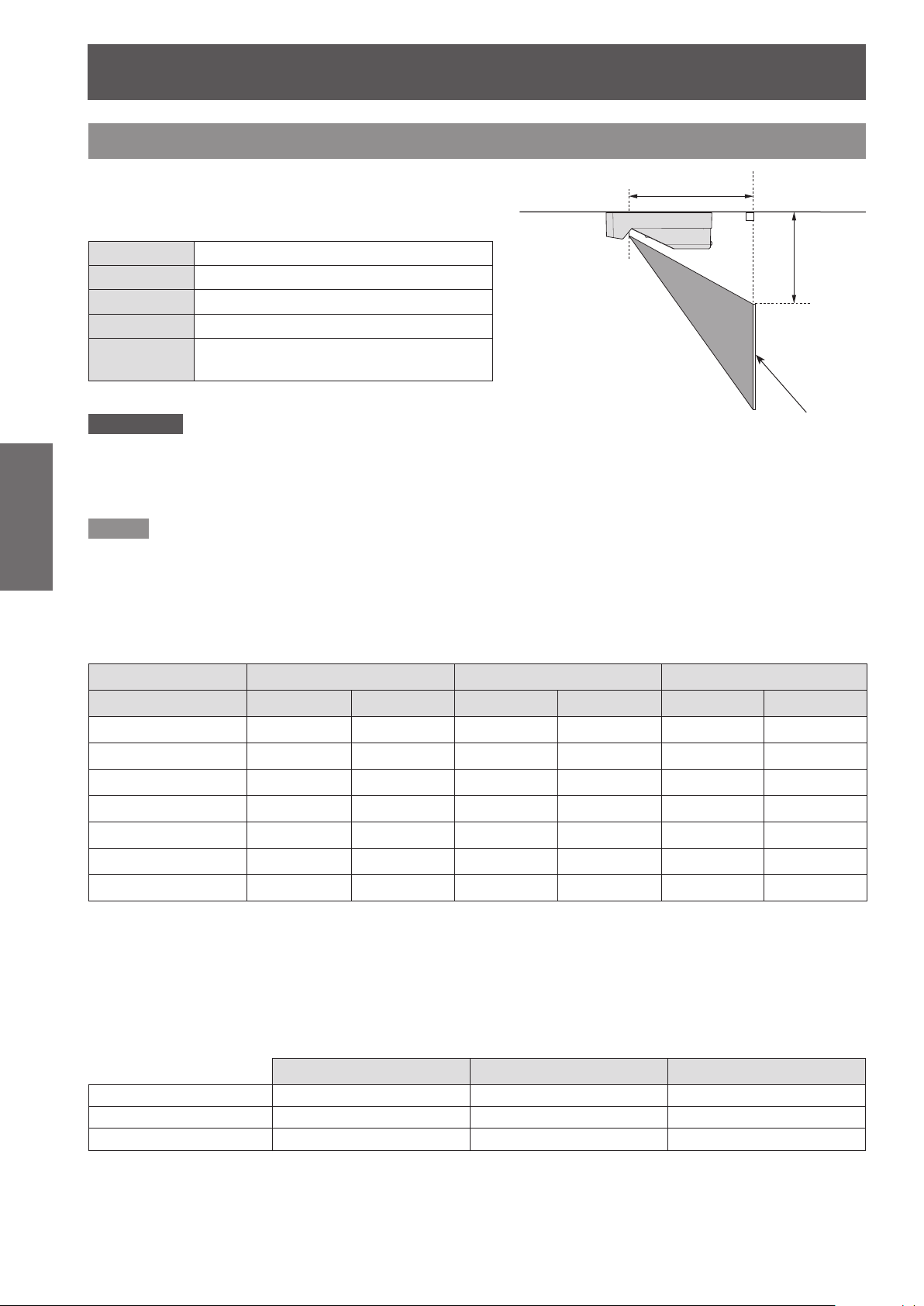
Screen size and throw distance
Place the projector referring to the diagram on the right
and the gures of throwing distance. You can adjust
the display size.
L Projection distance (cm)
SH Height of the projection area (m)
SW Width of the projection area (m)
SD Diagonal length of the projection area (m)
A
Height from bottom of projector to bottom
of screen (cm)
Attention
Before installing, please read “Precautions for Use” (
z
Special care should be used when DLP projectors are used in the same room as high power laser equipment. Direct or
z
indirect hitting of a laser beam on to the lens can severely damage the DMD element in which case there is a loss of
warranty.
Note
When projecting to wall or at objects, even slight warpage or irregularities of the screen may have an effect on the quality
z
of the projected images.
J
Projection distance for PT-CW230EA
(All measurements below are approximate and may differ slightly from the actual measurements.)
Projection size For 4:3 aspect ratio For 16:9 aspect ratio For 16:10 aspect ratio
Screen diagonal (SD) L A L A L A
1.40 m(55") 24.0 cm(0.79') 22.9 cm(0.75') - - - -
1.52 m(60") 26.5 cm(0.87') 24.1 cm(0.79') 23.7 cm(0.78') 27.0 cm(0.89') 23.0 cm(0.75') 22.5 cm(0.74')
1.78 m(70") 31.6 cm(1.04') 26.4 cm(0.87') 28.4 cm(0.93') 29.7 cm(0.97') 27.5 cm(0.90') 24.5 cm(0.80')
2.03 m(80") 36.7 cm(1.20') 28.6 cm(0.94') 33.0 cm(1.08') 32.5 cm(1.07') 32.0 cm(1.05') 26.5 cm(0.87')
2.29 m(90") 41.8 cm(1.37') 30.9 cm(1.01') 37.6 cm(1.23') 35.3 cm(1.16') 36.5 cm(1.02') 28.5 cm(0.94')
2.54 m(100") - - 42.2 cm(1.39') 38.0 cm(1.25') 41.0 cm(1.35') 30.5 cm(1.00')
pages 12 to 16).
Æ
Screen
2.79 m(110") - - - - 45.5 cm(1.49') 32.5 cm(1.07')
* Install the projector where the projection distance should be within 23.0 cm and 45.5 cm in order to keep the
lens performance.
Any other projection distance can be obtained according to the screen dimensions (m) using the following
calculations.
The distance is shown in units of meters. (The calculated distance may contain a certain error.)
If the screen dimensions are written as “SD",
For 4:3 aspect ratio For 16:9 aspect ratio For 16:10 aspect ratio
Screen height (SH) = SD(m) × 0.6 = SD(m) × 0.490 = SD(m) × 0.530
Screen width (SW) = SD(m) × 0.8 = SD(m) × 0.872 = SD(m) × 0.848
Projection distance (L) = 0.200425 × SD(m) - 0.039967 = 0.18196 × SD(m) - 0.039967 = 0.1770 × SD(m) - 0.039967
Page 23
Setting up
ENGLISH -
23
Getting Started
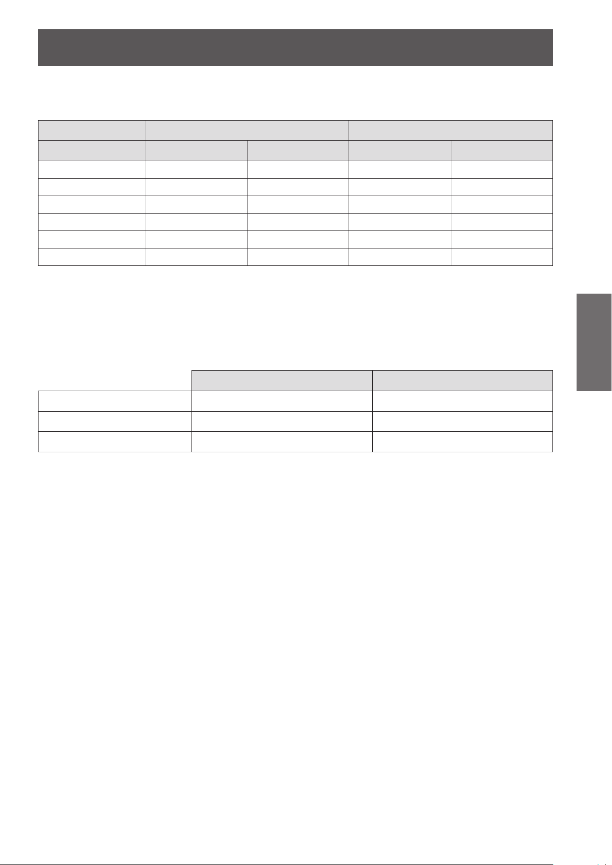
J
Projection distance for PT-CX200EA
(All measurements below are approximate and may differ slightly from the actual measurements.)
Projection size For 4:3 aspect ratio For 16:9 aspect ratio
Screen diagonal (SD) L A L A
1.27 m(50") - - 24.8 cm(0.81') 35.5 cm(1.17')
1.40 m(55") 25.1 cm(0.82') 25.2 cm(0.83') 27.7 cm(0.91') 38.0 cm(1.25')
1.52 m(60") 27.7 cm(0.91') 26.6 cm(0.87') 30.6 cm(1.00') 40.5 cm(1.33')
1.78 m(70") 33.0 cm(1.08') 29.3 cm(0.96') 36.4 cm(1.19') 45.5 cm(1.49')
2.03 m(80") 38.3 cm(1.26') 31.9 cm(1.05') 42.1 cm(1.38') 50.5 cm(1.66')
2.29 m(90") 43.7 cm(1.43') 34.6 cm(1.14') - -
* Install the projector where the projection distance should be within 23.0 cm and 45.5 cm in order to keep the
lens performance.
Any other projection distance can be obtained according to the screen dimensions (m) using the following
calculations.
The distance is shown in units of meters. (The calculated distance may contain a certain error.)
If the screen dimensions are written as “SD",
For 4:3 aspect ratio For 16:9 aspect ratio
Screen height (SH) = SD(m) × 0.6 = SD(m) × 0.490
Screen width (SW) = SD(m) × 0.8 = SD(m) × 0.872
Projection distance (L) = 0.2092 × SD(m) - 0.041703 = 0.227909 × SD(m) - 0.041703
Page 24
Setting up
24
- ENGLISH
Getting Started
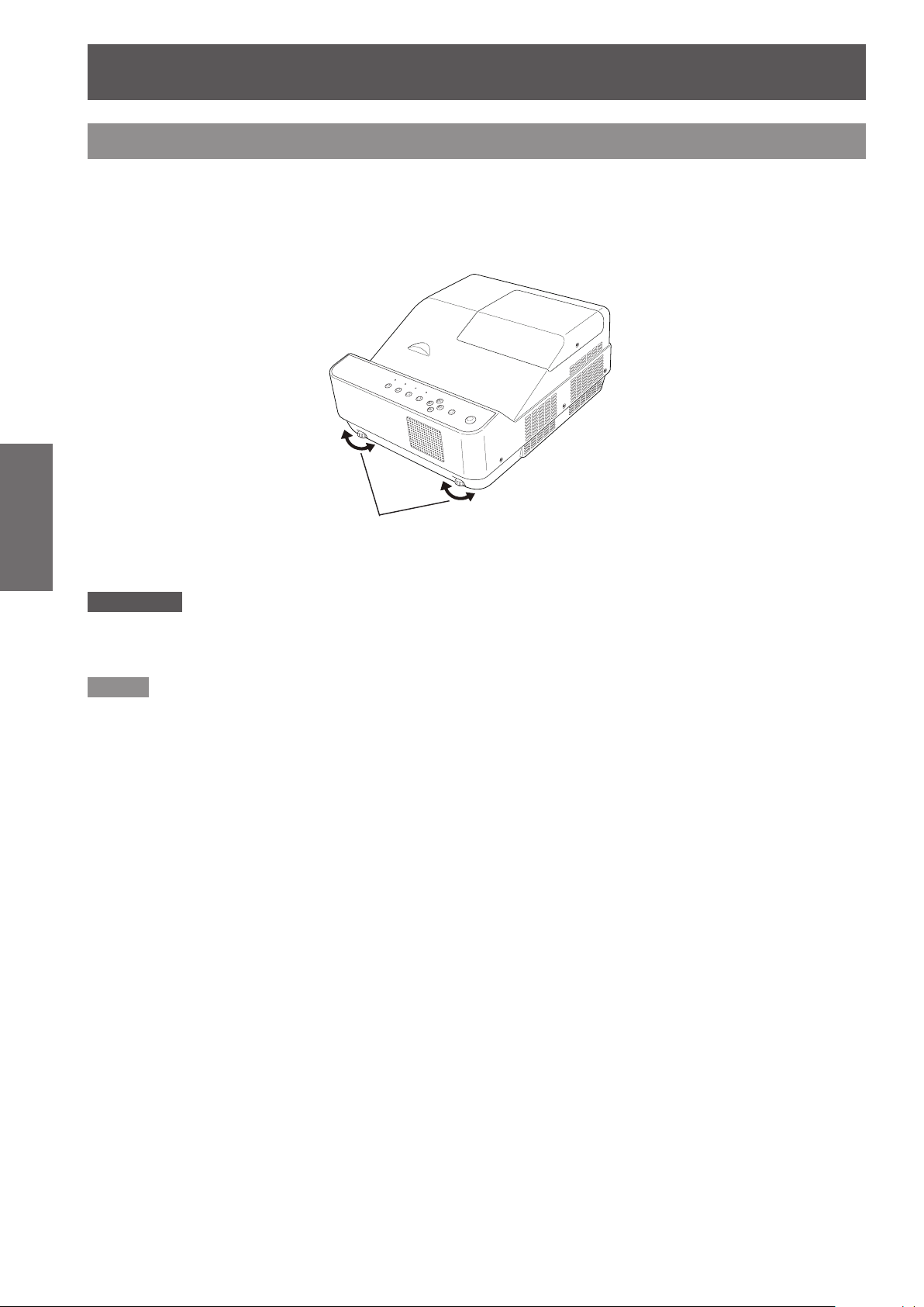
Adjusting front adjustable feet
Lift the front of the projector
You can turn the front adjustable feet to extend them. You can turn them in the opposite direction to contract
them.
(You can adjust the projection angle vertically.)
Attention
Heated air comes out of the air exhaust port while the lamp is lit. Do not touch the air exhaust port directly when you adjust
z
the front adjustable feet.
If keystone distortion occurs on the projected image, perform “KEYSTONE” from the “Screen” menu. (
z
and rotate the adjustable feet to a proper height and tilt.
Adjustable range: 1.0 degree
page 50)
Æ
Note
z
Screw up the adjustable feet, and an audible click will be heard as the limit.
Page 25
ENGLISH -
25
Getting Started
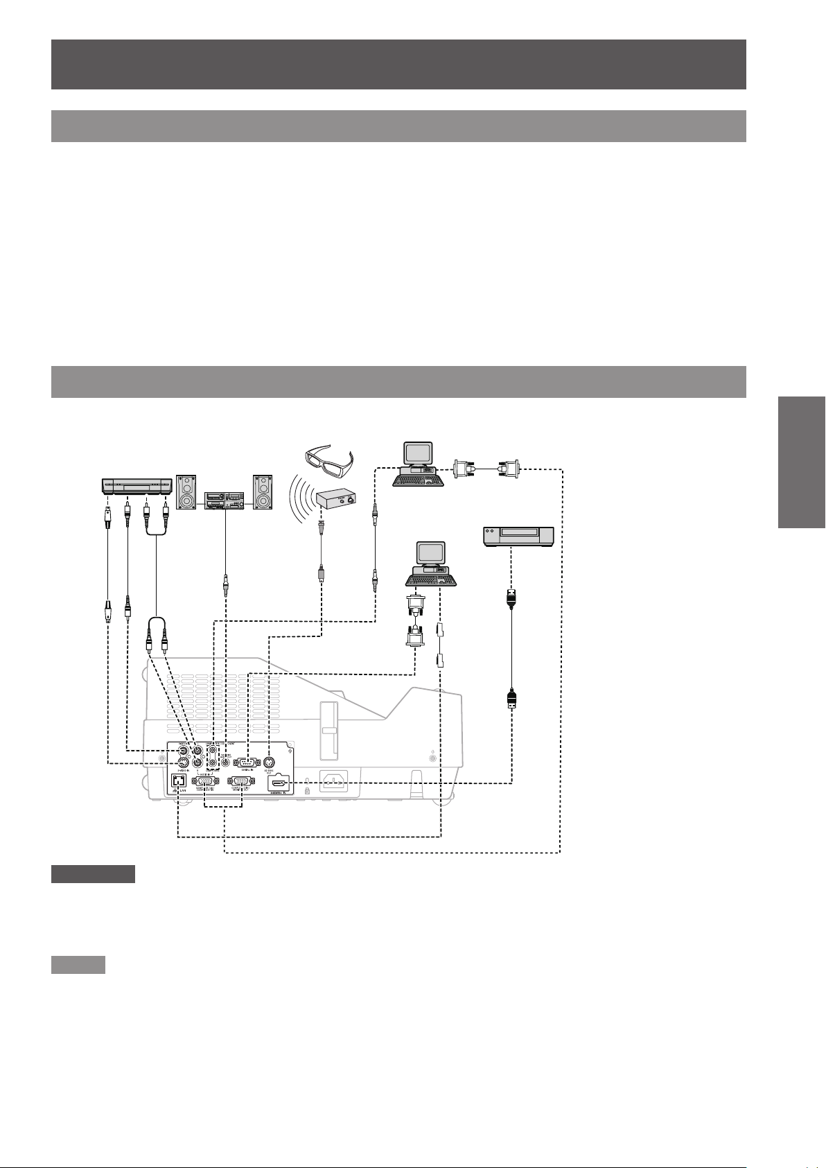
Connections
Before connecting to the projector
z
Read carefully the instruction manual for the device to be connected.
z
Turn off the power switch of the devices before connecting cables.
z
If any connection cable is not supplied with the device, or if no optional cable is available for connection of the
device, prepare a necessary system connection cable to suit the device.
z
Video signals containing too much jitter may cause the images on the screen to randomly wobble or wafture.
In this case, a time base corrector (TBC) must be connected.
z
The projector accepts the following signals: VIDEO, S-VIDEO, analogue-RGB (with TTL sync. Level) and
digital signal.
z
Some computer models are not compatible with the projector.
z
When using long cables to connect with each of equipment to the projector, there is a possibility that the image
will not be output correctly unless a compensator is used.
z
For details on what video signals the projector supports, see “List of compatible signals”. (
Connecting example
pages 73-76)
Æ
Video deck
(TBC built-in)
Audio system
3D glasses
Computer
Control computer
Blue ray disk player with HDMI
IN terminal
Attention
When connecting with a video deck, be sure to use the one with a built-in time base corrector (TBC) or use a TBC between
z
the projector and the video deck.
If nonstandard burst signals are connected, the image may be distorted. If this is the case, connect a TBC between the
z
projector and the video deck.
Note
When using an HDMI cable, check that it is compliant with the HDMI standard. Using a cable that is not compliant with the
z
HDMI standard may result in problems such as the image cutting out or not appearing.
When connecting the 1 080p signal using HDMI, use a cable compliant with 1 080p signal.
This projector does not support the Viera link (HDMI).
z
For the specications of the RGB signals that can be applied from the PC, refer to “List of compatible signals”.
z
(Æpages
See “Network operation” in the instruction manual on the supplied CD-ROM for the details of wired LAN communication
z
between the projector and the computer.
73-76
)
Page 26

26
- ENGLISH
Basic Operation
Powering ON/OFF
Bottom View
Connecting the power cord
Be sure to insert the attached power cord securely to its base to prevent it from coming off.
J
Power cord holder
A power cord holder is designed to prevent the AC power cord from coming off the projector.
Please insert the power cord into the power cord holder correctly as Picture (1) shown:
AC Power cord holder
Clamp
Picture (1)
J
Attaching
Attach the AC power cord with the power cord clamp to the projector by following these steps.
Plug the power cord with the power cord holder to the projector as Picture (2) shown.1 )
Push the clamp at the AC Power cord holder downward to secure it to the projector. It is correctly attached 2 )
until you hear the "CLICK" sound. See Picture (3) for correct attachment.
Picture (2) Picture (3)
Page 27

Powering ON/OFF
ENGLISH -
27
Basic Operation
ON(G)/STANDBY(R) indicator
ON(G)/STANDBY(R) indicator
The <ON(G)/STANDBY(R)> indicator informs you the status of the power. Conrm the status of the <ON(G)/
STANDBY(R)> indicator before operating the projector.
Indicator status Status
No illumination or ashing The power cord is unplugged.
The power cord is plugged.
The projector is in stand-by mode, after the cooling is completed.
The projector is cooling down. The projector cannot be turned on until cooling is
completed and the <ON(G)/STANDBY(R)> indicator stops blinking.
The temperature inside the projector is abnormally high and the projector is cooling
down. And the <WARNING> indicator also blinks in red (Æpage 61). The projector
cannot be turned on until cooling is completed and the <ON(G)/STANDBY(R)>
indicator stops blinking.
The projector is in stand-by status with [Power management] function.
The projection lamp will be turned on if the input signal is reconnected or any
button on the control panel or remote control is pressed. (Æpage 56)
RED
GREEN
Lit
Flashing
Lit Projecting.
Flashing
Page 28

Powering ON/OFF
28
- ENGLISH
Basic Operation
Turning On the Projector
(2)
(3)
(3)
Complete peripheral connections (with a 1 )
computer, VCR, etc.) before turning on the
projector.
Connect the projector’s AC power cord into an 2 )
AC outlet. The <ON(G)/STANDBY(R)> indicator
lights red.
Press the 3 )
the remote control. The <ON(G)/STANDBY(R)>
indicator lights green and the cooling fans start
to operate. The preparation display appears on
the screen and the count down starts.
After the countdown, the input source that was 4 )
selected the last time and the lamp power status
icon appear on the screen.
If there is no signal input when start on the 5 )
projector, or the current signal is missed while
operating the projector, the Video/Computer
selection window will be displayed on the screen,
please move the pointer to input source desired
by pressing the ▲▼ and the <SELECT> button.
And then follow the input signal guidance window
to correct the signal and connection.
< >
button on the control panel or
Preparation display
06
The preparation display will disappear
after 30 seconds.
Initial display
Input source
Lamp power status
Video/Computer selection
If the projector is locked with a PIN code, PIN
code input dialog box will appear. Enter the PIN
code as instructed on the next page.
Note
When the [Logo select] function is set to [Off], the logo
z
will not be shown on the screen (Æpage 55).
When [Countdown off] or [Off] is selected in the [Display]
z
function, the preparation display will not be shown on the
screen (Æpage 54).
When the [Input search] function is set to [On 2], the
z
input signal will be searched automatically (Æpage 53).
When the [Direct on] function is set to [On], the projector
z
will be turned on automatically by connecting the AC
power cord to an AC outlet.
Page 29

Powering ON/OFF
ENGLISH -
29
Basic Operation
Enter a PIN code
Press ▲▼ to enter a number. Press ► to x the
number and move the red frame pointer to the next
box. The number changes to . If you xed an
incorrect number, use the ◄ button to move the
pointer to the number you want to correct, and then
enter the correct number.
Repeat this step to complete entering a four-digit
number.
After entering the four-digit number, move the pointer
to “Set”. Press the <SELECT> button so that you can
start to operate the projector.
If you entered an incorrect PIN code, PIN code and
the number (
the correct PIN code all over again.
Note
If the PIN code number is not entered or wrong PIN code
z
number is entered within three minutes after the PIN
code dialog box appeared, the projector will be turned off
automatically.
The “1234” is set as the initial PIN code at the factory.
z
) will turn red for a moment. Enter
PIN Code Input Dialog Box
After the OK icon disappears,
you can operate the projector.
Page 30

Powering ON/OFF
30
- ENGLISH
Basic Operation
Turning Off the Projector
Press the <1 ) > button on the control panel or
the remote control, and
the screen.
Press the <2 ) > button on the control panel or
the remote control again to turn off the projector.
The <ON(G)/STANDBY(R)> indicator starts to
blink red, and the cooling fans keep running.
At this time, you can unplug the AC power cord
even if the fans are still running.
When the projector has cooled down enough, the 3 )
<ON(G)/STANDBY(R)> indicator stops blinking
and you can turn on the projecto
Note
Do not put the projector in a case before the projector is
z
cooled enough.
While the
z
the lamp is being cooled down and the projector cannot
be turned on. Wait until the
indicator stops blinking to turn on the projector again.
The projector can be turned on after the
z
STANDBY(R)>
to restart will be shortened when the normal power-off
processing for fan cooling is completed, compared with
the time the AC power cord is immediately unplugged
after the power-off.
To protect the component parts inside the projector, the
z
fans normally start running again in approximately 40
seconds after turning off the projector. This is NORMAL
operation and not a malfunction.
Power off?
<ON(G)/STANDBY(R)>
<ON(G)/STANDBY(R)>
indicator turns red. The waiting time
indicator is blinking,
appears on
r.
<ON(G)/
Power off?
disappears after 4 seconds.
J
Direct Power Off function
You can disconnect the power cord from the wall
outlet or turn off the breaker even during projection
without pressing the < > button.
Note
When using the Direct power Off function, you can
z
not restart the projector immediately after the power is
disconnected. The lamp remains high temperature and
needs to be cooled, so it sometimes takes longer time
than usual for the lamp to light up again.
Page 31

ENGLISH -
31
Basic Operation
Projecting
Check the connections of the peripheral devices and connection of the power cord (Æpage 26) and switch on the
power (Æpage 28) to start the projector. Select the image and adjust the state of the image.
Selecting the image
Select an input signal.
The image selected with the <COMPUTER 1>, <COMPUTER 2>, <HDMI>, <VIDEO>, <S-VIDEO>, or
<COMPONENT> button is projected (Æpages 40-41).
Attention
Images may not be projected properly depending on the connected device and DVD, video tape, etc. to be played. Set a
z
system format that is suitable for the input signal in [Component], [S-video] and [Video] in the [Input] menu (Æpage 40).
Check the aspect ratio of the screen and the image and select the optimum aspect ratio under the [Screen] menu
z
(Æpage 49).
How to adjust the state of the image
J
Zoom and Image Position Adjustment
Press the ZOOM +/- buttons on the control panel to adjust the screen size. Screen size can be adjusted 84% to
100% from its maximum screen size.
It is not available when On-Screen menu is displayed.
Zoom adjustment can be memorized (Æpage 54).
The image position can be adjusted in the Zoom Adjustment by the following steps:
Press the ZOOM+ or ZOOM- button on the control panel.1 )
While ZOOM+ or ZOOM- is displayed on the screen, press the <SELECT> button. Arrow marks displayed 2 )
on the screen.
▲▼◄►
Press 3 )
Note:
Zoom and Image Position Adjustment can not be operated when 4:3 or 16:9 mode is selected in the [Screen aspect] menu
z
or [Custom] is selected in the [Screen] menu.
The image position adjustment can not be adjusted at ZOOM maximum.
z
The white arrows indicate that there is no correction.
z
A red arrow indicates the direction of correction.
z
An arrow disappears at the maximum correction.
z
J
Focus Adjustment
Adjust the lens focus with the focus lever.
z
buttons on the control panel or the remote control to adjust the image position.
Note
z
z
Focus Lever
It is recommended that the images are projected continuously for at least 30 minutes before the focus is adjusted.
If keystone distortion occurs, see “KEYSTONE”. (
page 50)
Æ
Page 32

Projecting
32
- ENGLISH
Basic Operation
For Viewing 3D Contents
To view 3D images, you need to prepare at least the 3D active shutter glasses, 3D content and 3D reproducing
equipment. For example, as for computer, when transmitting 3D signals from a computer to the projector, you
also need to install the graphic card which has the capability to sequentially output the 3D frames at 120Hz and
software in the computer. The 3D signal type which the projector can accept is frame sequential only. Other 3D
signal types such as frame packing and side-by-side are not supported.
As for 3D glasses, DLP Link format and IR emitter format are compatible with this projector. Compatibility with
any other 3D glasses than the 2 types 3D glasses is not guaranteed.
In a situation of using NVIDIA 3D glasses, NVIDIA IR emitter, and a computer which NVIDIA graphics card is
installed, when you want to view NVIDIA-compatible 3D contents, please set to NVIDIA 3D VISION mode.
Attention
COMPUTER 2 IN/MONITOR OUT terminal is not supported NVIDIA 3D VISION. Please input the image signals to
z
COMPUTER 1 IN/COMPONENT IN or HDMI terminal.
J
Using 3D Glasses with DLP Link compatible
When using DLP Link compatible glasses, follow these steps:
Turn on the projector and the 3D glasses.1 )
Wear the 3D glasses and press the 3D button on the remote control to activate 3D Display function. 2 )
When 3D mode is in On, 3D indicator turns blue.
If you see a discrete or overlapping image, 3D Sync Invert function enables you to get the correct image. 3 )
Press the 3D button to switch 3D Sync signal from among "3D Off", "3D (Sync 1)", "3D (Sync 2)" or "3D
VISION".
Note
3D setting can also be selected from the menu.
z
J
Using 3D Glasses with IR wireless emitter
When using IR emitter system, follow these steps:
Turn off the projector.1 )
Connect the sync cable for the IR emitter to 3D SYNC OUT terminal of the projector.2 )
Turn on the projector, the IR emitter and the stereoscopic wireless LCD glasses.3 )
Wear the 3D glasses and press the 3D button on the remote control to activate 3D Display function.4 )
Note
If you see a discrete or overlapping image, press the 3D button to switch 3D Sync signal from among "3D Off", "3D (Sync 1)",
z
"3D (Sync 2)" or "3D VISION".
You can also invert the sync signal by using the switch on the IR emitter.
z
(Æpage 54)
Attention
Before viewing 3D contents, please read "Precaution for use". (
z
pages 14-15)
Æ
Page 33

ENGLISH -
33
Basic Operation
Basic operations by using the remote control
Using the AUTO SETUP function
COMPUTER 1
COMPUTER 2
HDMI
VIDEO
S-VIDEO
COMPONENT
Switch to Computer 1(RGB)/
Computer 1(Scart) input.
Switch to Computer 2(RGB)input.
Switch to HDMI input.
Switch to Video input.
Switch to S-video input.
Switch to Computer 1
(Component) input.
Using the SCREEN button
This function allows you to select screen mode or
change the screen size.
button
Press the <SCREEN> button on the
remote control.
This function allows you to automatically adjust Input
search, and Auto PC adjustment during signal input
from a computer.
button
Press the <AUTO SETUP> button on the
remote control.
Note
For details, see “Setting” of Main menu. (
z
page 53)
Æ
Switching the input signal
You can switch the input signals to project.
buttons
z
Note
For details, see “Screen” of Main menu. (
page 49)
Æ
Press (<COMPUTER 1>,<COMPUTER 2>,
<HDMI>, <VIDEO>, <S-VIDEO>, or
<COMPONENT>) button on the remote
control.
Page 34

Basic operations by using the remote control
34
- ENGLISH
Basic Operation
Using the KEYSTONE button
This function allows you to correct keystone distortion.
Press the <KEYSTONE> button on the control panel
or the remote control. The Keystone dialog box
appears. Press ▲▼ to correct keystone distortion.
The keystone adjustment can be stored (Æpage 50).
Operation Screen image
Reduce the
upper width
with press
.
▲
Reduce the
lower width
with press
.
▼
button
Using the INFO. button
This function allows you to display the information
menu.
button
Press <INFO.> button on the remote
control.
Note
For details, see “Input Source Information Display ” in
z
“Information” under Main menu (Æpage 60).
Using the FREEZE function
You can freeze the projected image and stop the
sound temporarily, regardless of the playing condition
of the connected device.
button
Note
The white arrows indicate that there is no correction.
z
A red arrow indicates the direction of correction.
z
An arrow disappears at the maximum correction.
z
If you press the <KEYSTONE> button on the control
z
panel or the remote control once more while the keystone
dialog box is being displayed, the keystone adjustment
will be canceled (Æpage 50).
The adjustable range is limited depending on the input
z
signal.
Press the <FREEZE> button on the remote control to
freeze the picture on the screen, meanwhile, volume
is muted. To cancel the Freeze function, press the
<FREEZE> button again or press any other button.
Fig.1 will appear on the screen while the Freeze
function is working.
Fig.1
Note
When no signal inputs,
z
mark will appear.
Page 35

Basic operations by using the remote control
ENGLISH -
35
Basic Operation
Using the AV MUTE function
button
Press the < AV MUTE> button on the remote control
to black out the image. To restore to normal, press the
< AV MUTE> button again or press any button.
The screen changes each time you press the
z
< AV MUTE> button as follows.
black out
Note
When use the <MUTE> button to release the [
z
function, the mute function can not be operated at the
same time.
projected image
AV mute]
Using the P-TIMER button
Using the D.ZOOM buttons
This function allows you to enter to the Digital zoom
+/– mode.
buttons
Press <D.ZOOM+/-> buttons on the
remote control.
Note
For details, see "Screen" of Main menu. (
z
Æ
Controlling the volume of the
speaker
You can control the volume of the projector’s speaker
or audio output.
page 49)
Press the <P-TIMER> button on the remote control to
operate the [Count up] function. The Timer display “00
: 00” appears on the screen and starts to count time
(00 : 00–59 : 59).
button
Press <P-TIMER> button on the remote
control.
Note
To stop the P-timer, press the <P-TIMER> button.
z
To cancel the P-timer, press the <P-TIMER> button
z
again.
Using the LAMP button
This function allows you to select the lamp mode for
changing the brightness on the screen.
buttons
Press the <VOLUME+/–> buttons on the control panel
or on the remote control to adjust the volume. The
volume dialog box appears on the screen for a few
seconds.
Note
For details, see “Volume” of "Sound" under Main menu.
z
(Æpage 52)
Using the IMAGE button
This function allows you to select a desired image
mode of the screen.
button
button
Press <LAMP> button on the remote
control.
Note
For details, see “Lamp Power” of "Setting" under Main
z
menu. (Æpage 57)
Press <IMAGE> button on the remote control to select
the desired image mode among [Dynamic], [Standard],
[Real], [Cinema], [Image 1], [Image 2], [Image 3] and
[Image 4].
Note
For details, see “Image select” of Main menu.
z
(Æpage 45)
Page 36

Basic operations by using the remote control
Using the 3D button
This function allows you to operate the 3D function.
button
Press <3D> button on the remote control.
Note
For details, see “3D” of "Setting" under Main menu.
z
(Æpage 54)
Using the MUTE button
Press this button on the remote control to select [On]
to temporarily turn off the sound.
button
Press <MUTE> button on the remote
Basic Operation
control.
Note
To turn the sound back on, press this button again to
z
select [Off] or press the <VOLUME+/–> buttons.
(Æpage 52)
36
- ENGLISH
Page 37

Menu Navigation
Navigating through the menu
J
Operating procedure
Press the <MENU> button.1 )
The Main Menu screen appears.
Press ▲▼ to select the Main Menu 2 )
item.
Select the desired item from the 9 items: [Input],
[PC adjust], [Image select], [Image adjust],
[Screen], [Sound], [Setting], [Information] and
[Network]. The selected item is highlighted with an
orange cursor and the submenu of the selected
item appears on the right.
Press ► or the <SELECT> button.3 )
The submenu appears so that you can select the
sub-menu item.
Press ▲▼ to select the desired sub-4 )
menu item.
Press the <SELECT> button or press 5 )
► to enter the desired item.
Press ▲▼ ◄► to set or adjust the 6 )
parameter values.
Press ◄ to return the previous menu. 7 )
Press the <MENU> button to exit the
menu display.
Note
Some items may not be adjusted or used for certain
z
signal formats input to the projector. The MENU items
that cannot be adjusted or used are shown in gray
characters, and they cannot be selected.
Some items can be adjusted even if signals are not input.
z
See pages 38 and 39 for details on the items of sub-
z
menu.
Settings
ENGLISH -
37
Page 38

Menu Navigation
38
- ENGLISH
Settings
Main menu
The main menu consists of the following 9 menu
items.
When a main menu item is selected, the screen
changes to a submenu selection screen.
Input
PC adjust
Image select
Image adjust
Screen
Sound
Setting
Information
Network
Sub menu
The sub-menu screen of the selected main menu
appears, and you can set and adjust the various items
in the submenu.
J
Input [ ]
Sub-menu item
Computer 1 RGB 40
Computer 2 RGB 40
HDMI - 41
Video - 41
S-video - 41
J
PC adjust [
Sub-menu item
AUTO PC adj. - 42
Fine sync. - 43
Total dots - 43
Horizontal - 43
Vertical - 43
Current mode - 44
Clamp - 44
Reset - 44
Mode free - 44
Store - 44
]
Factory
default
Factory
default
Page
Page
Note
This function will be available when the input source
z
come from computer.
J
Image select [ ]
Sub-menu item
Dynamic - 45
Standard - 45
Real - 45
Cinema - 45
Image 1-4 - 45
Factory
default
Page
Page 39

Menu Navigation
ENGLISH -
39
Settings
Image adjust [ ]
J
Setting [
]
Sub-menu item Factory default Page
Contrast 32 46
Brightness 32 46
1
Color*
1
Tint*
Color temp. Mid 46
Red 32 47
Green 32 47
Blue 32 47
Sharpness 8 47
Gamma Default 47
Noise reduction*
Progressive*
Reset - 48
Store - 48
When input video signal to the projector, these *1 :
functions will be available.
J
Screen [
Sub-menu item Factory default Page
Normal - 49
Full - 49
Wide (16:9) - 49
Zoom - 49
1
True*
Natural wide*
Custom - 49
Custom adj. - 50
Digital zoom + *
Digital zoom - *
Keystone Store 50
Ceiling Off 51
Rear Off 51
Screen aspect*
Colorboard Off 51
Reset - 51
When input computer signal to the projector, these *1 :
functions will be available.
PT-CW230EA Only.*2 :
1
1
]
2
1
1
2
32 46
32 46
L1 47
L1 48
- 49
- 49
- 50
- 50
Default(16:10) 51
Sub-menu item Default Page
Language English 53
Menu position Center 53
Auto setup - 53
3D setting - 54
Zoom Store 1 54
Background Blue 54
Display On 54
Logo - 55
HDMI setup - 55
Terminal Computer 2 55
Power management Shut down 56
Direct on Off 56
Standby mode Eco 56
Closed caption Off 56
Lamp power Normal 57
Remote control Code 1 57
Security - 57
Fan L2 58
Fan control Off 58
Lamp runtime - 58
Filter counter - 58
Factory default - 59
J
Information [
Sub-menu item Factory default Page
Input - 60
H-sync freq. - 60
V-sync freq. - 60
Screen - 60
Language - 60
Lamp power - 60
Lamp runtime - 60
Power management - 60
Key lock - 60
PIN code lock - 60
Remote control - 60
Serial number - 60
]
J
Sound [
Sub-menu item Default Page
Volume 32 52
Mute Off 52
]
J
Network [ ]
Refer to “Operating Instructions, Network operations”.
Page 40

40
- ENGLISH
Settings
Input menu
Select [Input] from the Main Menu (see
“Navigating through the menu” on page 37),
then select the item from the sub-menu.
Remote Control
Control Panel
Computer 1: RGB/Component /RGB (Scart)
Press ▲▼ to select [Computer 1]. 1 )
Press ► to access the submenu.2 )
Press ▲▼ to select [RGB], 3 )
[Component] or [RGB(Scart)].
Computer 2: RGB
Press ▲▼ to select [Computer 2 (RGB)]
and then press the <SELECT> button.
J
Computer System Selection
This projector automatically tunes to various types
of computers with its Multi-scan system and Auto
PC Adjustment. If a computer is selected as a signal
source, this projector automatically detects the signal
format and tunes to project a proper image without
any additional settings. (Signal formats provided in
this projector are shown on pages 73-76.)
When the projector can not recognize the
Auto
connected signal conforming to the
provided PC Systems, Auto is displayed
on the System Menu box and the Auto PC
images. If the image is not projected
properly, a manual adjustment is required.
There is no signal input from the computer.
- - - -
Check the connection between your
computer and the projector.
adjustment function works to display proper
The preset system is manually adjusted in
Mode 1
the PC adjust Menu. The adjusted data can
be stored in Mode 1-10.
PC Systems provided in this projector
SVGA 1
is chosen. The projector chooses a proper
system provided in the projector and
displays it.
* Mode 1 and SVGA 1 are examples.
Press ▲▼ to select [System].1 )
Press ► or the <SELECT> button to 2 )
access the submenu.
Press ▲▼ to select the desired system.3 )
Page 41

Input menu
ENGLISH -
41
Settings
HDMI
Press ▲▼to select [HDMI] and then press
the <SELECT> button.
Video
Press ▲▼ to select [Video] and then
press the <SELECT> button.
S-video
Press ▲▼ to select [S-video] and then
press the <SELECT> button.
J
Video System Selection
The projector automatically detects an incoming video
system, and adjusts itself to optimize its performance.
Note
When the [Input Search] function is set to [On 1] or
z
[On 2] in the [Auto setup] function, the input signal will be
searched automatically.
The [System] menu cannot be selected when the input is
z
selected to [HDMI], [Video], [S-video] or [RGB(Scart)].
Page 42

AUTO PC adjust
Select [PC adjust] from the Main Menu (see
“Navigating through the menu” on page 37),
then select the item from the sub-menu.
Remote Control
Control Panel
AUTO PC adj.
[Auto PC adjustment] function is provided to
automatically adjust [Fine sync], [Total dots],
[Horizontal] and [Vertical] positions to conform to your
computer.
Press ▲▼ to select [AUTO PC adj.] and
then press the <SELECT> button.
z
[Please wait...]
adjustment] is in process.
appears while the [Auto PC
Settings
To store adjustment parameters
The adjusted parameters from the [Auto PC
adjustment] can be stored in the projector. Once the
parameters are stored, the setting can be done just by
selecting a Mode (1–10) in the PC System Menu (see
page 40). See also [Store] on page 44.
Attention
[Fine sync], [Total dots], [Horizontal] and [Vertical]
z
position of some computers cannot be fully adjusted
with the [Auto PC adjustment] function. When the image
is not provided properly with this operation, manual
adjustments are required (Æpages 43-44).
The [Auto PC adjustment] cannot be operated when
z
[480i], [576i], [480p], [576p], [720p] or [1 080i] is selected
in the PC System Menu (Æpage 40), or when the signal
is coming from the HDMI IN terminal.
42
- ENGLISH
Page 43

Manual PC adjust
Select [PC adjust] from the Main Menu (see
“Navigating through the menu” on page 37),
then select the item from the sub-menu.
Remote Control
Some computers employ special signal formats
which may not be tuned by Multi-scan system of this
projector. Manual PC adjustment enables you to
precisely adjust several parameters to match those
signal formats. The projector has 10 independent
memory areas to store those parameters manually
adjusted. It allows you to recall the setting for a
specic computer.
Control Panel
Horizontal
Press ▲▼ to select [Horizontal].1 )
Press the <SELECT> button to display 2 )
the adjustment dialog box.
Press ◄► to adjust the horizontal 3 )
picture position.
J
For horizontal (right and left)
adjustment
Operation Adjustment
The picture
Press ◄.
Press ►.
position
moves to the
right.
The picture
position
moves to the
left.
Fine sync
Press ▲▼ to select [Fine sync].1 )
Press the <SELECT> button to display 2 )
the adjustment dialog box.
Press ◄► to adjust the value.3 )
z
The value can be adjusted from 0 to 31.
Total dots
Press ▲▼ to select [Total dots].1 )
Press the <SELECT> button to display 2 )
the adjustment dialog box.
Press ◄► to adjust the value.3 )
Vertical
Press ▲▼ to select [Vertical].1 )
Press the <SELECT> button to display 2 )
the adjustment dialog box.
Press ◄► to adjust the vertical picture 3 )
position.
J
For vertical (up and down)
adjustment
Operation Adjustment
The picture
Press ►.
Press ◄.
position
moves up.
The picture
position
moves down.
Settings
ENGLISH -
43
Page 44

Manual PC adjust
44
- ENGLISH
Settings
Current mode
Press ▲▼ to select [Current mode].1 )
Press ► or the <SELECT> button 2 )
to enter the next submenu to show
H-sync freq. and V-sync freq. of the
connected computer.
Clamp
Press ▲▼ to select [Clamp].1 )
Press the <SELECT> button to display 2 )
the adjustment dialog box.
Press ◄► to adjust the clamp level.3 )
z
When the image has dark bars, try this
adjustment.
Reset
To reset the adjusted data, all adjustments will return
to their previous gures.
Press ▲▼ to select [Reset].1 )
Press the <SELECT> button.2 )
z
A conrmation box appears and then select [Yes].
Mode free
Press ▲▼ to select [Mode free].1 )
Press ► or the <SELECT> button to 2 )
enter the next submenu.
z
Move the highlight to the mode that you want to
clear and then press the <SELECT> button.
z
A conrmation box appears and then select [Yes].
Store
Press ▲▼ to select [Store].1 )
Press ► or the <SELECT> button to 2 )
enter the next submenu.
z
z
Move the highlight to one of the Modes 1 to 10
in which you want to store, and then press the
<SELECT> button.
A conrmation box appears and then select [Yes].
Page 45

ENGLISH -
45
Settings
Image select
Select [Image select] from the Main Menu (see
“Navigating through the menu” on page 37),
then select the item from the sub-menu.
Remote Control
Control Panel
Dynamic
For viewing pictures in a bright room.
Press ▲▼ to select [Dynamic] and then
press the <SELECT> button.
Image 1-4
For viewing with the user preset image mode in the
Image adjust Menu.
Press ▲▼ to select [Image 1-4] and then
press the <SELECT> button.
Standard
Normal picture mode preset on the projector.
Press ▲▼ to select [Standard] and then
press the <SELECT> button.
Real
Picture mode with improved halftone for graphics.
Press ▲▼ to select [Real] and then press
the <SELECT> button.
Cinema
Picture mode adjusted with ne tone.
Press ▲▼ to select [Cinema] and then
press the <SELECT> button.
Page 46

Image adjust
Settings
Select [Image adjust] from the Main Menu (see
“Navigating through the menu” on page 37),
then select the item from the sub-menu.
Remote Control
Note
Make sure you selected [Store] after adjusting settings.
z
Some settings can not be stored if not registered with
[Store] function.
Control Panel
Contrast
Press ▲▼ to select [Contrast].1 )
Press the <SELECT> button to display 2 )
the adjustment dialog box.
Press ◄► to adjust the setting value.3 )
Operation Adjustment
Press ►. increase the contrast
Press ◄.
decrease the
contrast
Adjustment
range
Maximum
value 63
Minimum
value 0
Color
Press ▲▼ to select [Color].1 )
Press the <SELECT> button to display 2 )
the adjustment dialog box.
Press ◄► to adjust the setting value.3 )
Operation Adjustment
Press ►.
Press ◄.
Note
When input video signal to the projector, [Color] will be
z
available.
increase the
intensity of the color
decrease the
intensity of the color
Tint
Press ▲▼ to select [Tint].1 )
Press the <SELECT> button to display 2 )
the adjustment dialog box.
Press ◄► to adjust the tint value to 3 )
get a proper color balance.
z
Adjustments can be made between
Note
When you select [NTSC] or [NTSC4.43] in System menu
z
under Video input signal, [Tint] will be available.
Adjustment
range
Maximum
value 63
Minimum
value 0
0 and 63.
Brightness
Press ▲▼ to select [Brightness].1 )
Press the <SELECT> button to display 2 )
the adjustment dialog box.
Press ◄► to adjust the setting value.3 )
Operation Adjustment
Press ►.
Press ◄.
46
- ENGLISH
increase the
brightness
decrease the
brightness
Adjustment
range
Maximum
value 63
Minimum
value 0
Color temp.
Press ▲▼ to select [Color temp.].1 )
Press the <SELECT> button to display 2 )
the adjustment dialog box.
Press ◄► to select the desired Color 3 )
temp. level.
z
You can select the desired [Color temp.] from
[XLow], [Low], [Mid] or [High].
Page 47

Image adjust
Red
Press ▲▼ to select [Red].1 )
Press the <SELECT> button to display 2 )
the adjustment dialog box.
Press ◄► to adjust the setting value.3 )
Operation Adjustment
Press ►. deepen red tone
Press ◄. lighten red tone
Green
Press ▲▼ to select [Green].1 )
Press the <SELECT> button to display 2 )
the adjustment dialog box.
Press ◄► to adjust the setting value.3 )
Adjustment
range
Maximum
value 63
Minimum
value 0
Sharpness
Press ▲▼ to select [Sharpness].1 )
Press the <SELECT> button to display 2 )
the adjustment dialog box.
Press ◄► to adjust the setting value.3 )
Operation Adjustment
increase the
Press ►.
Press ◄.
sharpness of the
image
decrease the
sharpness of the
image
Gamma
Press ▲▼ to select [Gamma].1 )
Press the <SELECT> button to display 2 )
the adjustment dialog box.
Adjustment
range
Maximum
value 15
Minimum
value 0
Operation Adjustment
Press ►.
Press ◄.
deepen green
tone
lighten green
tone
Blue
Press ▲▼ to select [Blue].1 )
Press the <SELECT> button to display 2 )
the adjustment dialog box.
Press ◄► to adjust the setting value.3 )
Operation Adjustment
Press ►. deepen blue tone
Press ◄. lighten blue tone
Adjustment
range
Maximum
value 63
Minimum
value 0
Adjustment
range
Maximum
value 63
Minimum
value 0
Press ◄► to adjust the gamma value 3 )
to obtain a better balance of contrast.
z
Adjustments can be made among
[Default/1.8/2.0/2.2/2.4/2.6].
Noise reduction
Press ▲▼ to select [Noise reduction].1 )
Press the <SELECT> button to display 2 )
the adjustment dialog box.
Press ◄► to select the desired item3 )
Off
L 1
L 2
z
Noise interference on the screen can be
reduced. Select one of the above options to get
smoother images.
Note
When input video signal to the projector, [Noise
z
reduction] will become available.
[Noise reduction] cannot be selected when [480p],
z
[576p],
[Noise reduction] cannot be selected when [On]
z
or [NVIDIA 3D VISION] is selected in [3D] of [3D
setting].
Disabled
Lower reduction
Higher reduction
[720p] or [1 080p]
is selected.
Settings
ENGLISH -
47
Page 48

Image adjust
Progressive
Press ▲▼ to select [Progressive].1 )
Press the <SELECT> button to display 2 )
the dialog box.
Press ◄► to select the desired item.3 )
z
An interlaced video signal can be displayed in
progressive mode. Select one of the following
options.
Settings
Off
L 1
L 2
Film
Note
When input video signal to the projector, [Progressive]
z
will become available.
[Progressive] cannot be selected when [480p],
z
[576p],
[Film] cannot be selected when [1 080i] is selected.
z
[Progressive] cannot be selected when [On] or
z
[NVIDIA 3D VISION] is selected in [3D] of [3D
setting].
Disabled
For an active picture
For a still picture
For watching a lm
[720p] or [1 080p]
is selected.
Reset
To reset the adjusted data, all adjustments will return
to their previous gures.
Press ▲▼ to select [Reset].1 )
Press the <SELECT> button.2 )
z
Store
Press ▲▼ to select [Store].1 )
Press ► or the <SELECT> button.2 )
Press ▲▼ to select one from Image 1 3 )
to 4 and press the <SELECT> button.
z
48
- ENGLISH
A conrmation box appears and then select [Yes].
A conrmation box appears and then select [Yes].
Page 49

Screen
Select [Screen] from the Main Menu (see
“Navigating through the menu” on page 37),
then select the item from the sub-menu.
Remote Control
Control Panel
Normal
Provide the image to t the screen size while
maintaining the aspect ratio of the input signal.
Press ▲▼ to select [Normal] and then
press the <SELECT> button.
True
Provide the image in its original size. When the
original image size is larger or smaller than the
panel size (1 280 x 800),* the projector enters to the
panning mode automatically.
Press ▲▼ to select [True] and then 1 )
press the <SELECT> button.
Press ▲▼◄► to pan the image.2 )
z
When adjusted, the arrows will turn red. When
reached to the correction limits, the arrows will
disappear.
Screen size (1 280 x 800) is only for PT-CW230EA.
*
Screen size (1 024 x 768) is for PT-CX200EA.
Note
When input computer signal to the projector, [True] will
z
be available.
[True] is disabled and cannot be displayed when [480i],
z
[576i], [480p], [576p], [720p] or [1 080i] is selected in the
PC System Menu.
When [True] is selected in the Screen menu, [Digital
z
zoom +/-] can not be selected
.
Full
Provide the full screen image.
Press ▲▼ to select [Full] and then press
the <SELECT> button.
Wide(16:9)
Provide the image at the 16:9 wide screen ratio.
Press ▲▼ to select [Wide(16:9)] and then
press the <SELECT> button.
Zoom
Scale the image proportionally to t the entire screen.
Either side of image may go over the screen.
Press ▲▼ to select [Zoom] and then
press the <SELECT> button.
Natural wide
(PT-CW230EA Only)
Modify the 4:3 aspect ratio image to t the screen size
by stretching the image to make it look natural.
Press ▲▼ to select [Natural wide] and
then press the <SELECT> button.
Note
When input video signal to the projector, [Natural wide]
z
will be available.
[Natural wide] is not available when [720p] or [1 080i] is
z
selected in the PC System Menu.
Custom
Provide the last stored aspect screen image.
Press ▲▼ to select [Custom] and press
the <SELECT> button.
Settings
ENGLISH -
49
Page 50

50
- ENGLISH
Settings
Screen
Custom adj.
Adjust the screen scale and position manually with
this function.
Press ▲▼ to select [Custom adj.].1 )
Press ► or the <SELECT> button to 2 )
enter the next submenu.
Press ▲▼ to choose the item you 3 )
want to adjust.
z
You can choose one from the items as below:
Scale H/V
H&V
Position H/V
Common
Reset
Adjust the Horizontal/Vertical screen
scale.
When set to [On], the aspect ratio is
xed.
Adjust the Horizontal/Vertical screen
position.
Save the adjusted scale or position
to all the inputs.
Reset the all adjusted values.
To exit the Digital zoom +/– mode, press any button
except the <D.ZOOM +/->, <SELECT> and ▲▼◄►
buttons.
To return to the previous screen size, select a screen
size from the Screen Size Adjustment Menu or select
an input source from the Input Source Selection Menu
(Æpages 40-41) again, or adjust the screen size with
the <D.ZOOM +/-> buttons.
Note
When input computer signal to the projector, this function
z
will be available.
[Digital zoom +/-] cannot be selected when [True] is
z
selected in the Screen aspect
[Digital zoom +/–] are disabled and cannot be displayed
z
when [480i], [576i], [480p], [576p], [720p], [1 080i] or
[1 080p] is selected in the PC System Menu
When [Digital zoom +/–] functions are disabled,
z
mark will appear.
.
page 40).
(
Æ
Keystone
Digital zoom +
Zoom in the images.
Press ▲▼ to select [Digital zoom +] 1 )
and then press the <SELECT> button.
z
The On-Screen Menu disappears and
[D. zoom + ] appears.
Press the <SELECT> button to zoom in 2 )
the image size and press ▲▼ ◄► to
move the image to the top/bottom/left/
right of the screen.
z
The Panning function can work only when the
image is larger than the screen size. A projected
image can be also expanded by pressing the
<D.ZOOM +>
or the <SELECT> button.
Digital zoom -
Zoom out the images.
Press ▲▼ to select [Digital zoom -] 1 )
and then press the <SELECT> button.
z
The On-Screen Menu disappears and
[D.zoom - ] appears.
This function is used to adjust keystone distortion of
the projected image.
Press ▲▼ to select [Keystone].1 )
Press ► or the <SELECT> button.2 )
Press ▲▼ to choose the item you 3 )
want to adjust.
Keystone
Store
Store
Reset
To correct keystone distortion
To store or reset the keystone
correction
The following items are the
submenu of [Store].
Keep the keystone correction even
when the AC power cord is plugged
out or turned off the projector.
Release the keystone correction
when the AC power cord is plugged
out.
Press the <SELECT> button to zoom 2 )
out image size.
z
The projected image can be also compressed
by pressing the
button.
<D.ZOOM ->
or the <SELECT>
Page 51

ENGLISH -
51
Settings
Screen
Ceiling
This function is used to project the image from a
ceiling-mounted projector.
Press ▲▼ to select [Ceiling] and then 1 )
press the <SELECT> button.
Press ▲▼ to change the image.2 )
z
When this function is set to [On], the picture will
be top/bottom and left/right reversed.
Rear
This function is used to project the image from rear of
the screen.
Press ▲▼ to select [Rear] and then 1 )
press the <SELECT> button.
Press ▲▼ to change the image.2 )
z
When this function is set to [On], the picture will
be left/right reversed.
Colorboard
For the image projected on a colorboard.
Press ▲▼ to select [Colorboard].1 )
Press ► or the <SELECT> button to 2 )
display the submenu.
z
Adjustments can be made among [Off/Red/
Blue/Yellow/Green/Blackboard(Green)].
Reset
To reset the adjusted data, all adjustments will return
to their previous gures.
Press ▲▼ to select [Reset] and then
press the <SELECT> button.
z
A conrmation box appears and then select
[Yes].
Screen aspect
(PT-CW230EA Only)
This function is used to project the image to a 4:3 or
16:9 projection screen.
Press ▲▼ to select [Screen aspect] 1 )
and then press the <SELECT> button.
Press ▲▼ to choose one from the 2 )
items as below.
Default(16:10)
16:9
4:3
Attention
When the [4:3] function is selected, [Natural wide] is not
z
available in the AV screen.
When the [16:9] function is selected, [Wide (16:9)] is not
z
available in the AV screen.
16:10 is the aspect of the DLP
chips.
Set to a 16:9 projection screen.
Set to a 4:3 projection screen.
Page 52

Sound
Select [Sound] from the Main Menu (see
“Navigating through the menu” on page 37),
then select the item from the sub-menu.
Settings
Remote Control
Control Panel
Volume
Press ▲▼ to select [Volume] and then 1 )
press the <SELECT> button.
Press ◄► to adjust the volume.2 )
z
Press <SELECT> button to set the volume.
Operation Adjustment
Press ►.
Press ◄.
z
You can also press <VOLUME+/–> buttons on
the remote control or control panel to adjust the
volume.
turn up the
volume
turn down the
volume
Adjustment
range
Maximum
value 63
Minimum
value 0
Mute
Press ▲▼ to select [Mute] and then 1 )
press the <SELECT> button.
Press the <SELECT> button to switch 2 )
the mute function [On]/[Off].
z
52
- ENGLISH
Press the <MUTE> button on the remote
control to temporarily turn off the sound. To turn
the sound back on, press the <MUTE> button
again or press the <VOLUME+/–> buttons.
Page 53

Setting
Select [Setting] from the Main Menu (see
“Navigating through the menu” on page 37),
then select the item from the sub-menu.
Remote Control
Control Panel
Language
Press ▲▼ to select [Language].1 )
Press ► or the <SELECT> button.2 )
Press ▲▼ to select the desired 3 )
language.
Menu position
This function is used to change the position of the OnScreen Menu.
Press ▲▼ to select [Menu position].1 )
Press the <SELECT> button to change 2 )
the position.
z
The Menu position changes each time you
press <SELECT> button as follows:
the center → the bottom left → the bottom right → the
top left → the top right → the center......
Auto setup
Press ▲▼ to select [Auto setup].1 )
Press ► or the <SELECT> button.2 )
Press ▲▼ to select these functions as 3 )
follows:
The language used in the On-Screen Menu is
z
available in English, German, French, Italian,
Spanish, Portuguese, Dutch, Swedish, Finnish,
Norwegian, Danish, Polish, Hungarian, Romanian,
Russian, Turkish, Arabic, Kazak, Simplied
Chinese, Traditional Chinese, Korean, Japanese
and Tha
i.
J
Input search
This function detects the input signal automatically.
When a signal is found, the search will stop.
Off
On 1
On 2
●When pressing the <AUTO SETUP> button on the *1 :
remote control or the control panel.
●When turning on the projector by pressing the *2 :
panel.
●
the remote control or the control panel.
●
* If the [AV mute] or [Freeze] function is active,
cancel it to activate the Input search. It is also
unavailable when On-Screen menu is displayed.
J
Auto PC adj.
On
Off
When pressing the <AUTO SETUP> button on *1 :
the remote control or the control panel.
Input search will not work
Input search works*
Input search works*
button on the remote control or the control
< >
When pressing the<AUTO SETUP> button on
When the current input signal is cut off.*
Enables Auto PC adjustment *
Disables Auto PC adjustment
1
2
1
Settings
Note
[Input search] and [Auto PC adj.] cannot be set [Off] at
z
the same time.
ENGLISH -
53
Page 54

Setting
54
- ENGLISH
Settings
3D setting
This function is used to set the 3D display function.
Press ▲▼ to select these functions as
follows:
J
3D
Select among [Off], [On] and [NVIDIA 3D VISION]
mode.
* When selecting [NVIDIA 3D VISION] mode, the
other menus [3D sync], [3D->2D], [3D phase]
setting are not necessary. (displayed in gray)
J
3D sync
If you see a discrete or overlapping image, 3D
Sync Invert function* enables you to get the
correct image. Switch the 3D sync signal to 1 or 2.
J
3D->2D
When viewing the 3D contents without wearing
the 3D glasses, set to "On" to convert 3D display
format to 2D display format.
J
3D phase
Adjust the phase of the 3D sync signal when the
3D SYNC OUT terminal is used. (0 - 31)
Note
The Frame Sequential Format is a technology that
z
rapidly alternates between left-eye and right-eye
images. When right-eye image and left-eye image
are switched or you feel like you cannot get 3D
effect due to out-of- synchronization state, first try
to synchronize the projector with the 3D glasses by
using 3D SYNC function.
Zoom
This function is used to memorize the Zoom
adjustment with the <ZOOM +/-> buttons on the
control panel.
Press ▲▼ to switch between each option
as below.
Background
Select the background screen for when no input signal
is detected.
Press ▲▼ to select [Background].1 )
Press the <SELECT> button.2 )
Press ▲▼ to switch3 )
between each
option as below.
Blue
Black
Blue colored background.
Black colored background.
Display
This function decides whether to display O n-Screen
Displays.
Press ▲▼ to select [Display].1 )
Press the <SELECT> button.2 )
Press ▲▼ to switch3 )
option as below.
On
Countdown
off
Off
Use this function when you want to project *1 :
images after the lamp becomes bright enough.
The factory default setting is in this option.
Use this function when you want to project the *2 :
image as early as possible even when the lamp
is not bright enough.
Hide the On-Screen Displays except; *3 :
● On-Screen Menu.
● [Power off?]
● [P-timer] display.
● No signal for [Power management]
● [Please wait ...]
● Arrows for the True function in the Screen
Menu.
Show all the On-Screen
displays *
Show the input image instead
of the countdown when turning
on the projector *
Hide the On-Screen Displays *
between each
1
2
3
Reset
Store1
Store2
Reset the Zoom adjustment when the
projector is turned off or the AC power
cord is unplugged.
Store the Zoom setting even when the
projector is turned off. Zoom setting
is cleared when the AC power cord is
unplugged.
Store the Zoom setting even when the
AC power cord is unplugged.
Page 55

Setting
ENGLISH -
55
Settings
Logo
This function allows you to customize the screen logo
with [Logo select], [Logo PIN code lock] and [Logo
PIN code change] functions.
Press ▲▼ to select [Logo].1 )
Press ► or the <SELECT> button.2 )
Press ▲▼ to choose the desired item.3 )
J
Logo select
This function decides on the starting-up display from
among following options.
Off
Default
J
Logo PIN code lock
This function prevents an unauthorized person from
changing the screen logo.
Off
On
Show the countdown display only.
Show the factory-set logo.
The screen logo can be changed freely
from the Logo Menu.
The screen logo cannot be changed
without a Logo PIN code.
HDMI setup
This function is only used for HDMI input source.
Press ▲▼ to select [HDMI setup].1 )
Press ► or the <SELECT> button.2 )
z
The names for the output setting of Digital R/G/
B vary from equipment to equipment.
J
Image
Normal
Enhanced
J
Sound
HDMI
Computer
1
Note
For details, refer to the operating instructions of your
z
Digital R/G/B equipment.
When the output of Digital R/G/B
equipment is set to Standard.
When the output of Digital R/G/B
equipment is set to Enhanced.
When Digital input source is input,
Sound is set to HDMI.
When DVI input source is changed
to HDMI input source, Sound is set
to Computer 1.
Note
If you want to change the Logo PIN code lock setting,
z
press the <SELECT> button and the Logo PIN code
dialog box appears. Enter a Logo PIN code by following
the steps below. The initial Logo PIN code is set to “4321”
at the factory.
J
Logo PIN code change
Logo PIN code can be changed to your desired fourdigit number.
Press ▲▼ to select [Logo PIN code 1 )
change] and press the <SELECT>
button.
z
Current logo PIN code dialog box appears.
Press ▲▼ to enter the current code, 2 )
press the ► button to x the number
and move the red frame pointer to the
next box.
z
The New Logo PIN code input dialog box
appears.
Repeat this step to set the new Logo 3 )
PIN code.
Terminal
The COMPUTER 2 IN/MONITOR OUT terminal on
the back of the projector is switchable for computer 2
input or monitor output.
Press ▲▼ to select [Terminal] and 1 )
then press the <SELECT> button.
Press ▲▼ to switch the item.2 )
Computer 2
Monitor out
Note
Terminal function is not available when selecting
z
[Computer 2] to the input source. Change the input
source to the others (Computer 1, HDMI,S-video or
Video) so that the Terminal function will be available.
Computer input
Monitor out
Attention
Be sure to note the new Logo PIN code and keep it on
z
hand. If you lost the number, you could no longer change
the Logo PIN code setting.
Page 56

Setting
56
- ENGLISH
Settings
Standby mode
This function can set the electric power when the
projector is standing by.
Press ▲▼ to select [Standby mode] 1 )
and then press the <SELECT> button.
J
Timer
Press ▲▼ to select [Timer] and then 1 )
press the <SELECT> button.
Press ▲▼ to set the Timer(1~30min).2 )
Press ▲▼ to switch between the items 2 )
as below.
Restricts some functions in
Eco
Network
Note
When selecting [Network], the cooling fans may be
z
running depending on the temperature inside the
projector even if the projector is turned off.
Refer to "Operating Instructions - Network Operations
z
If Standby mode is set to [Eco], you cannot use network
z
functions when the projector is standing by. Also, you
cannot use some RS-232C protocol commands.
If set to [Network], you can use network functions when
z
the projector is standing by.
standby mode to reduce power
consumption.
Does not restrict functionality
even in standby mode.
Power management
For reducing power consumption as well as
maintaining the lamp life, the Power management
function turns off the projection lamp when the
projector is not operated for a certain period.
Press ▲▼ to select [Power 1 )
management].
Press ► or the <SELECT> button to 2 )
access the submenu.
Direct on
Press ▲▼ to select [Direct on] and 1 )
then press the <SELECT> button.
Press ▲▼ to switch between [On] and 2 )
[Off].
z
When this function is set to [On], the projector
will be automatically turned on just by
connecting the AC power cord to a wall outlet.
z
Be sure to turn off the projector properly. If the
projector is turned off in the incorrect sequence,
".
the [Direct On] function does not work properly.
Closed caption
Only for NTSC input
[
Press ▲▼ to select [Closed caption].1 )
Press ► or the <SELECT> button to 2 )
enter the submenu.
J
Closed caption
Press ▲▼ to select [Closed caption] 1 )
and then press the <SELECT> button.
Press ▲▼ to select [Off], [CC1], [CC2], 2 )
[CC3] or [CC4].
]
J
Mode
Press ▲▼ and then press the 1 )
<SELECT> button to select one mode
among the items as below.
Ready
Shut
down
Off
When the lamp has been fully cooled
down, the <ON(G)/STANDBY(R)>
indicator changes to green blinking.
In this condition, the projection lamp
will be turned on if the input signal
is reconnected or any button on the
control panel or remote control is
pressed
When the lamp has been fully cooled
down, the power will be turned off.
[Power management] function is off.
J
Color
Press ▲▼ to select [Color] and then 1 )
press the <SELECT> button.
Press▲▼ to select [Color] or [White].2 )
Note
The closed caption is mainly used in the north America.
z
This function shows the text information contained in the
image signal. Captions may not be displayed on some
devices or software.
You can select [Closed caption] when [NTSC] signal is
z
input.
Part of characters may not displayed when high
z
compensation values are set in [Keystone].
Closed captions are not displayed while the menu screen
z
appears.
Page 57

Setting
ENGLISH -
57
Settings
Lamp power
This function allows you to change brightness of the
screen.
Press ▲▼ to select [Lamp power] and 1 )
then press the <SELECT> button .
Press ▲▼ to select one among the 2 )
modes as below.
z
You can also press the <LAMP> button to
display [Lamp power].
Normal
Eco
Normal brightness.
Lower brightness reduces the
lamp power consumption and
extends the lamp life.
Remote control
This switching function prevents remote control
interference when operating several projectors or
video equipment at the same time.
Security
This function allows you to use the Key lock and PIN
code lock function to set the security for the projector
operation.
Press ▲▼ to select [Security].1 )
Press ► or the <SELECT> button to 2 )
access the submenu.
J
Key lock
This function locks the control panel and remote
control buttons to prevent operation by unauthorized
persons.
Press ▲▼ to select the desired items 1 )
as below.
Unlocked.
Lock the operation of the control
panel. To unlock, use the remote
control.
Lock the operation of the remote
control. To unlock, use the control
panel.
Press ▲▼ to select [Remote control].1 )
Press ► or the <SELECT> button.2 )
Press ▲▼ to select one among the 3 )
two codes.
z
This projector provides 2 different remote
control codes: [Code 1] and [Code 2].
Note
When different codes are set on the projector and on the
z
remote control, any operation cannot be made. In that
case, switch the code on the remote control to t the
code on the projector.
If the batteries are removed from the remote control for a
z
long period of time, the remote control code will be reset.
J
PIN code lock
This function prevents the projector from being
operated by unauthorized persons and provides the
following setting options for security.
Press ▲▼ to select the desired items 1 )
as below.
Off
On 1
On 2
Note
Whenever you change the PIN code lock setting or the
z
PIN code (the four-digit number), you are required to
enter the PIN code. The "1234" is set as the initial PIN
code at the factory.
Unlocked.
Enter the PIN code every time
turning on the projector.
Enter the PIN code to operate
the projector once the power cord
is disconnected; as long as the
AC power cord is connected, the
projector can be operated without
a PIN code.
Page 58

58
- ENGLISH
Settings
Setting
J
PIN code change
The PIN code can be changed to your desired fourdigit number.
Press ▲▼ to select [PIN code change] 1 )
and then Press <SELECT> button.
z
Current Pin code dialog box appears.
Press ▲▼ to enter the current code. 2 )
Press ► button to x the number and
move the red frame pointer to the next
box.
z
The New PIN code input dialog box appears.
Repeat these steps to set a new PIN 3 )
code.
Attention
Be sure to note the new PIN code and keep it on hand. If
z
you lost the number, you could no longer change the PIN
code setting.
Fan
Set this function to [Off] when using the projector *1 :
in non-high altitude environment.
Select this mode when using the projector in high *2 :
altitudes (about 1 000 meters or more above
the sea level) where the fans have less cooling
effect.
Select this mode when using the projector in *3 :
higher altitudes (than above where the fans have
lesser cooling effect).
It is recommended to select [On 1] when the altitudes
is over about 1 000 m and select [On 2] when the
altitudes is over about 2 000 m.
Note
Failure to set the running speed of cooling fans
z
properly may affect the projector life.
The fan noise becomes louder in [On 1] and [On 2].
z
Lamp runtime
This function is used to display the cumulative lamp
operating time and reset the lamp runtime.
Press ▲▼ to select [Fan] and then 1 )
press <SELECT> button.
Press ▲▼ to select one option.2 )
z
This function provides the following options in
the cooling fans’ operation when the projector is
turned off.
L 1
L 2
It takes less time to cool the
projector down than L 2 mode.
Slower and lower-sound than
L 1 mode, but it takes more time
to cool the projector down.
Fan control
Press ▲▼ to select [Fan control] and 1 )
then Press <SELECT> button.
Press ▲▼ to select one among 2 )
options as below.
z
Choose the running speed of cooling fans from
the following options according to the ground
elevation under which you use the projector.
Press ▲▼ to select [Lamp runtime].1 )
Press ►or the <SELECT> button to 2 )
access the submenu items.
J
Lamp runtime
Show the total accumulated lamp run time.
J
Lamp runtime reset
After replacing the lamp unit, be sure to reset the
timer.
Press ▲▼ to select [Lamp runtime 1 )
reset].
Press the <SELECT> button. 2 )
z
[Lamp runtime Reset?] appears. Select [Yes]
to continue. Another conrmation dialog box
appears, select [Yes] to reset the Lamp runtime.
Attention
When the lamp run time is elapsed the estimated
z
duration, [Lamp runtime] will be displayed in red
and the Lamp replacement icon (Æpage 64) will
appear on the screen, indicating that the end of
lamp life is reached. When replacing the lamp unit,
reset the lamp runtime.
Off
On 1
On 2
Normal speed.*
Faster than [Off] mode.*
Faster than [On 1] mode.*
1
2
3
Page 59

Setting
ENGLISH -
59
Settings
Filter counter
This function is used to set a frequency for the lter
replacement.
Press ▲▼ to select [Filter counter].1 )
Press ►or the <SELECT> button to 2 )
access the submenu items.
J
Filter counter
Show the total accumulated time of the lter use timer
setting.
J
Timer
To set a timer. When the projector reaches the
selected time the lter warning icon appears on the
screen.
Press ▲▼ to select [Timer] and then 1 )
press the <SELECT> button.
Press ▲▼ to set the Timer.2 )
z
Select from [Off/2000 H/3000 H/4000 H]
depending on the use environment.
J
Filter counter reset
After replacing the lter unit, be sure to reset the timer.
Press ▲▼ to select [Filter counter 1 )
reset].
Press the <SELECT> button. 2 )
z
[Filter counter Reset?] appears. Select [Yes]
to continue. Another conrmation dialog
box appears, select [Yes] to reset the [Filter
counter].
Factory default
This function returns all setting values except for the
[PIN code lock], [Logo PIN code lock], [Lamp runtime]
and [Filter counter] to the factory default settings.
Press ▲▼ to select [Factory default].1 )
Press the <SELECT> button.2 )
z
[Return to Factory default?] appears. Select
[Yes] to continue. Another conrmation dialog
box appears, select [Yes] to return to [Factory
default].
Page 60

Information
Select [Information] from the Main Menu (see
“Navigating through the menu” on page 37),
then select the item from the sub-menu.
Remote Control
Input Source Information
Control Panel
J
Lamp runtime
The cumulative lamp operating time is displayed.
J
Power management
[Off] , [Ready] or [Shut down], and [Timer] are
displayed.
J
Key lock
The selected Key lock icon is displayed.
J
PIN code lock
[Off], [On 1] or [On 2] is displayed.
J
Remote control
The selected remote control code is displayed.
Settings
Display
The Information Menu is used for checking the status
of the image signal being projected and the operation
of the projector.
You can also Press the <INFO.> button on the remote
control to display the Information menu.
J
Input
The selected input source is displayed.
J
H-sync freq.
The selected H-sync freq. is displayed.
The horizontal frequency of the input signal is
displayed in KHz, or - - - - kHz when no signal.
J
V-sync freq.
The selected V-sync freq. is displayed.
The vertical frequency of the input signal is displayed
in Hz, or - - - - Hz when no signal. Numbers of Hz
doubles when during Interlace.
J
Serial number
The serial number of the projector is displayed.
The serial number is used to service the projector.
J
Screen
The selected Screen size is displayed.
J
Language
The selected language is displayed.
J
Lamp power
The selected lamp mode is displayed.
60
- ENGLISH
Page 61

LAMP and WARNING Indicators
LAMP and WARNING Indicators
Managing the indicated problems
If a problem should occur inside the projector, the <ON(G)/STANDBY(R)> , <LAMP> and/or <WARNING>
indicators will inform you. Manage the indicated problems as follow.
CAUTION
Before you take a remedial measure, follow the procedure of switching the power off indicated in “Turning off the projector”.
z
(Æpage 30)
If multiple indicators light or blink, verify the status of the projector by looking at each indicator.
z
Note
Conrm the status of the power indicated on the
z
J
LAMP indicator
<ON(G)/STANDBY(R)>
indicator.
Indicator
Status
Check
Remedy
Note
Contact your dealer for repair services when <LAMP> indicator persists to light after taking these measurements.
z
J
WARNING indicator
Indicator
Status
Check
Remedy
Lights in yellow.
The projection lamp reaches its end of life.
Is there a Lamp replacement icon appears on the screen?
Replace the lamp unit.
(Æpage 65)
Lights in red. Blinks in red.
The projector detects an abnormal
condition and cannot be turned
on.
Unplug the AC power cord
and plug it again to turn on the
projector.
If the projector is turned off again,
unplug the AC power cord and
contact the dealer or the service
center for service and checkup.
The temperature inside the projector is abnormally high.
The projector cannot be turned on. And the <ON(G)/
STANDBY(R)> indicator also blinks in red.
- Did you provide appropriate space for the projector to be
ventilated? Check the installing condition to see if the air
vents of the projector are not blocked.
- Has the projector been installed near an Air-
Conditioning/ Heating Duct or Vent?
- Is the lter clean?
- Provide good installing condition to your projector.
- Move the installation of the projector away from the duct
or vent.
- Replace the lter unit.
Note
If <WARNING> indicator persists to light or blink after taking these measurements, please contact your dealer for repair
z
services. Do not leave the projector on. It may cause an electric shock or a re hazard.
The projector detects an abnormal condition and cannot be turned on. Unplug the AC power cord and plug it again to turn
z
on the projector. If the projector is turned off again, unplug the AC power cord and contact the dealer or the service center
for service and checkup. Do not leave the projector on. It may cause an electric shock or a re hazard.
ENGLISH -
Maintenance
61
Page 62

62
- ENGLISH
Maintenance
Replacement
Before replacing the unit
z
When you perform maintenance or replacement of the parts, make sure to turn off the power and disconnect
the power plug from the wall outlet. (Æpages 26, 30)
z
Be sure to observe the procedure “Turing off the projector” (
operation.
Maintenance
J
Outer Case
Wipe off dirt and dust using a soft dry cloth.
z
If the dirt is persistent, soak the cloth with water and wring it thoroughly before wiping. Dry off the projector
with a dry cloth.
z
Do not use benzene, thinner, or rubbing alcohol, other solvents, household cleaners, or chemical treated
dusters. Using them may cause deterioration of the outer case.
J
Glass surface of the projection window.
Wipe off the dirt and dust off the surface of the projection window with soft clean cloth.
z
Do not use a cloth that has an abrasive surface or a cloth that is moist, oily, or covered with dust.
z
Do not use excessive force when wiping the projection window as it is fragile.
page 30) when performing power supply
Æ
Attention
The projection window is fragile. Impacts or excessive force when wiping may scratch its surface.
z
Please handle with care.
Replacing the unit
J
Air lter unit
Filter prevents dust from accumulating on the optical
elements inside the projector. Should the air lter become
clogged with dust particles, it will reduce cooling fans’
effectiveness and may result in internal heat buildup
and adversely affect the life of the projector.
If a “Filter warning” icon appears on the screen,
replace the air lter unit immediately.
J
Replacement of the air lter unit
Open the lamp cover.1 )
z
First, turn off the projector and unplug the AC
power cord from the AC outlet. Then, clean up
the dust on the projector and around the air
vents. At last, loosen the screw and open the
lamp cover.
Lamp Cover
Screw
Air filter unit
Remove the air lter unit.2 )
z
Insert a new air lter unit.3 )
z
Close the lamp cover.4 )
z
Lift the air lter unit out of the projector.
Insert a new air lter unit back into the position.
Close the lamp cover and secure the screw.
Page 63

Replacement
ENGLISH -
63
Maintenance
J
Resetting the Filter Counter
Be sure to reset the Filter counter after replacing the air lter unit. (Æpage 59"
Attention
z
Turn off the power before you replace the air lter unit.
z
When attaching the air lter unit, make sure that the projector is stable, and work in an environment that is
safe, even in the event of the air lter unit dropping.
z
Do not operate the projector with the lter removed. Dust may accumulate on the optical elements degrading
picture quality.
z
Do not put anything into the air ports. Doing so may result in malfunction of the projector.
z
The air lter unit to be replaced should be an unused product.
z
After replacing the air lter, reset the lter counter. Otherwise, the power of the projector may be turned off for
safety.
Filter counter reset
")
Page 64

Replacement
64
- ENGLISH
Maintenance
J
Lamp unit
The lamp unit is a consumable component. You can check the total usage time using Lamp runtime in the
Information menu on page 60.
It is recommended to ask an authorized engineer to replace the lamp unit. Contact your dealer.
Consult your dealer to purchase a replacement lamp unit (ET-LAC100).
CAUTION:
■ Do not replace the lamp unit when it is hot. (Wait at least 1 hour after use.)
The inside of the cover can become very hot, take care to avoid burn injuries.
J
Notes on the replacement of the lamp unit
z
The luminous source of the lamp is made of glass and may burst if you hit it against a hard surface or drop
it.
Please handle with care.
z
A Phillips screwdriver is required for replacement of the lamp unit.
z
When replacing the lamp unit, be sure to hold it by the handle.
z
When replacing the lamp because it has stopped illuminating, there
is a possibility that the lamp may be broken. If replacing the lamp of a
projector which has been installed on the ceiling, you should always
assume that the lamp is broken, and you should stand to the side
of the lamp cover, not underneath it. Open the lamp cover gently.
Small pieces of glass may fall out when the lamp cover is opened.
If pieces of glass get into your eyes or mouth, seek medical advice
immediately.
z
The lamp contains mercury. Consult your local municipality or your
dealer about correct disposal of used lamp units.
Attention
Do not use other than designated lamp units.
z
The part numbers of accessories and separately sold components are subject to change without notice.
z
J
When to replace the lamp unit
The lamp unit is a consumable component. Brightness decreases according to duration of usage, so
periodical replacement of the lamp unit is necessary.
When the projection lamp of the projector reaches its end of life, the Lamp replacement icon appears on the
screen and <LAMP> indicator lights yellow. Replace the lamp with a new one promptly.
2 000 hours of use is a rough guideline, but is not a guarantee. The lamp runtime differs depending on the
*
setting of "Lamp power" menu.
Note
The Lamp replacement icon will not appear when the [Display] function is set to [Off] (
z
"Freeze" (Æpage 34), or "AV mute" (Æpage 35).
Lamp runtime
Over 2 000 hours
On screen
Lamp replacement icon
The message is displayed for 4 seconds. If you
press any button within the 4 seconds, the message
disappears.
LAMP indicator
Lights in yellow (even in
stand-by mode).
page 54), or during
Æ
Page 65

Replacement
ENGLISH -
65
Maintenance
J
Replacing the Lamp unit
CAUTION:
z
When the projector is mounted on a ceiling, do not work with your face close to the projector.
z
Attach the lamp unit and the lamp cover securely.
z
When you experience difculty in installing the lamp, remove it and try again. If you use force to install the
lamp, the connector may be damaged.
Turn off the Power by following the 1 )
procedure in “Turning off the projector"
(Æpage 30). Unplug the AC power cord.
Wait at least 1 hour and make sure
the lamp unit and surroundings are cool.
Use a Phillips screwdriver to loosen the 2 )
lamp cover xing screw and open the
lamp cover.
z
Open the lamp cover by pulling it slowly
toward the direction of the arrow.
Use a Phillips screwdriver to loosen 3 )
the two lamp unit xing screws until
the screws turn freely. Hold the used
lamp unit by its handles, and pull it
gently from the projector.
Insert the new lamp unit in correct 4 )
direction. Tighten the two lamp unit
xing screws securely with a Phillips
screwdriver.
Lamp unit fixing screws
Lamp cover
Lamp cover
fixing screw
Lamp unit
Handles
Close the lamp cover, and tighten the lamp cover xing screw securely with a 5 )
Phillips screwdriver.
z
Close the lamp cover by pushing it slowly opposite the direction of the arrow.
J
Resetting the Lamp Runtime
Be sure to reset the [Lamp runtime] after replacing the lamp unit. (Æpage 58 "
Lamp runtime reset
")
Page 66

66
- ENGLISH
Maintenance
Troubleshooting
Please check following points. For details, see the corresponding pages.
Power does not turn
on.
No picture appears.
The picture is fuzzy.
The color is pale or
grayish.
No sound from the
internal speaker
The remote control
does not operate.
The control buttons
of the projector do
not operate.
The picture does not
display correctly.
Picture from a
computer does not
appear.
Problem Cause
z
The power cord may not be connected.
z
No electric supply is at the wall outlet.
z
The circuit breakers have tripped.
z
I
s the <LAMP> indicator,
<ON(G)/STANDBY(R)>
> indicator lit or blinking?
z
The lamp cover has not been securely installed.
z
The video signal input source may not be connected to a terminal
properly.
z
The input selection setting may not be correct.
z
The [Brightness] adjustment setting may be at the minimum setting.
z
The input source which is connected to the projector may have a
problem.
z
The [AV mute] function may be in use.
z
The lens focus may not have been set correctly.
z
The projector may not be at the correct distance from the screen.
z
The projection window may be dirty.
z
The projector may be tilted too much.
z
[Color] or [Tint] adjustment may be incorrect.
z
The input source which is connected to the projector may not be
adjusted correctly.
z
RGB cable is damaged.
z
The input terminals may not have been correctly connected.
z
The volume may have been set to the minimum level.
z
The [AV mute] function may have been turned on.
When the AUDIO OUT is plugged-in, the projector's built-in speaker is
z
not available.
z
The [Mute] function may have been turned on.
z
The batteries may be weak.
z
The batteries may not have been inserted correctly.
z
The remote control signal receptor on the projector may be obstructed.
z
The remote control unit may be out of the operation range.
z
Strong light such as uorescent shine onto the signal receptor.
z
When different codes are set on the projector and on the remote contro
The control panel is not available if the control panel is locked at [Key
z
lock] under [Security] of [Setting] section.
z
There may be a problem with the VCR or other signal source.
z
A signal which is not compatible with the projector is being input.
z
The cable may be longer than the optional cable.
z
The external video output from a laptop computer may not be correct.
indicator, or <WARNING
l
. 57
Reference
page
—
—
—
27, 61
65
25
33
46
—
35
31
22
14
—
46
—
—
25
35, 52
35
19
36, 52
—
20
17
17
17
57
—
73-76
—
—
Page 67

Troubleshooting
ENGLISH -
67
Maintenance
Problem Cause
z
Picture from a HDMI
device does not
appear or picture is
not stable.
No sound is output
from a HDMI device.
Is the HDMI cable securely connected?
z
Turn off the power of the projector and the connected devices. Then turn
the power of the projector and the connected devices back on.
z
Isn't unsupported signal cable connected?
z
Set the sound channel of the attached device to Linear PCM.
z
If no audio signal is output during HDMI cable connection, connect the
audio cable to COMPUTER 1/COMPONENT AUDIO IN terminal and set
to "Computer 1" in "Sound" of "Setting" menu.
z
The image is
Check [PC adj.] or [Screen] and adjust them.
distorted or runs off.
The exclamation
z
Your operation is invalid. Operate correctly.
mark appears on
the screen.
z
3D contents appear
The glasses or the projector are set to 2D mode.
as 2D.
3D image is inverted.
z
3D mode is out of phase. (The data for right/left eyes is inverted.)
(3D image is not
correct.)
z
Image of glasses
Outside of the recommended viewing zone of the glasses.
has icker.
Reference
page
25
—
73-76
—
55
42, 49
—
32
32
32
z
Glasses does not
turn on.
The battery of the glasses is exhausted.
z
The projector is not set to 3D mode.
Note
z
If the problem persists, after conrming the contents of the table, please consult your dealer.
32
Page 68

68
- ENGLISH
Appendix
Technical Information
Next Command
PC � Projector
Projector � PC
Command
Response
More than 100ms
“C” “0”
“7”
CR
ACK
CR
Serial terminal
The serial connector which is on the connector panel of the projector conforms to the RS-232C interface
specication, so that the projector can be controlled by a personal computer which is connected to this connector.
J
Connection
Connecting terminals
on projector
D-Sub 9-pin (female)
Computer
D-Sub 9-pin (male)
J
Pin assignments and signal names
D-Sub 9-pin (female)
Outside view
J
Communication conditions
Signal level RS-232C-compliant Character length 8 bits
Sync. method Asynchronous Stop bit 1 bit
Baud rate 19 200 bps X parameter None
Parity None S parameter None
Pin No. Signal name Contents
Communication cable
— NC
TXD Transmitted data
RXD Received data
— NC
GND Earth
— NC
CTS
RTS
— NC
Connected internally
J
[When connected to a computer]
Cable specications
Projector
1 NC NC 1
2 2
3 3
4 NC NC 4
5 5
6 NC NC 6
7 7
8 8
9 NC NC 9
Computer (DTE
specications)
Page 69

Technical Information
ENGLISH -
69
Appendix
Next Command
PC � Projector
Projector � PC
Command
Response
More than 100ms
“C” “0”
“7”
CR
ACK
CR
(A few ms ~ 5s)
J
Functional Execution Command
Format
The projector control command is dened as one command line that starts with "C" and ends with carriage
return.
Command Function
C00 Turn the projector ON
C01 Turn the projector OFF
(immediately OFF)
C02 Turn the projector OFF
C04 Select HDMI
C05 Select Computer 1
C06 Select Computer 2
C07 Select Video
C09 Volume +
C0A Volume -
C0B Sound mute ON
C0C Sound mute OFF
C0D Video mute ON
C0E Video mute OFF
C0F Screen Normal Size
C10 Screen Wide Size
C1C Menu ON
C1D Menu OFF
C20 Brightness UP
C21 Brightness DOWN
C28 Direct on ON
Command Function
C29 Direct on OFF
C30 D.ZOOM +
C31 D.ZOOM C34 Select S-video
C3A Pointer RIGHT
C3B Pointer LEFT
C3C Pointer UP
C3D Pointer DOWN
C3F Enter
C43 Freeze ON
C44 Freeze OFF
C46 Zoom -
C47 Zoom +
C50 Select Computer 1 RGB
C51 Select Computer 1 SCART
C54 Select Computer 1 Component
C89 Auto PC adj.
C8E Keystone UP
C8F Keystone DOWN
Page 70

Technical Information
70
- ENGLISH
Appendix
PC � Projector
Projector � PC
Command
Processing
“C” “R”
“0”
CR
ACK
CR
(A few ms ~ 5s)
J
Status Read Command
Format
The projector control command is dened as one command line that starts with "CR" and ends with carriage
return.
Command Function Projector
CR0
CR6 Temperature Read
Status Read
Return
00 Power On
80 Stand-by mode
40 Countdown
20 Cooling down
10 Power Malfunction
28 Cooling down at the temperature anomaly
24 Cooling down at Power Management mode
04 Power Management mode after Cooling down
21 Cooling down after the projector is turned off when the lamps are out.
81 Stand-by mode after Cooling down when the lamp is out.
%1 %2
%3
? Communication failure
Projector status
%1 = Temperature at Sensor 1 (˚C)
%2 = Temperature at Sensor 2 (˚C)
%3 = Temperature at Sensor 3 (˚C)
(ex.) %1 = 12.3˚C, %2 = 23.4˚C, %3 = 34.5˚C
--> The projector displays “12.3 23.4 34.5”
( For each sensor, two digit and the tenth place numbers are displayed
with a space between each temperature.)
Page 71

Technical Information
ENGLISH -
71
Appendix
Other terminals
J
Pin assignments and signal names of <S-VIDEO IN> terminal
Outside view
J
Pin assignments and signal names of <COMPUTER 1 IN/COMPONENT
Pin No. Signal names
GND (luminance signal)
GND (color signal)
Luminance signal
Color signal
IN> terminal
Outside view
Pin No. Signal names
R/P
R
G/G SYNC/Y
B/P
B
+ 5 V
DDC data
HD/SYNC
VD
DDC clock
: Not assigned
- , , : GND terminals
J
Pin assignments and signal names of <COMPUTER 2 IN/MONITOR OUT>
terminal
Outside view
Pin No. Signal names
R
G
B
HD/SYNC
VD
, , , , : Not assigned
- , : GND terminals
Page 72

Technical Information
72
- ENGLISH
Appendix
J
Pin assignments and signal names of <HDMI> terminal
Outside view
Even-numbered
Odd-numbered
J
Pin assignments and signal names of <3D SYNC OUT> terminal
Outside view
pins to
pins to
Pin No. Signal names Pin No. Signal names
T.M.D.S data 2+ T.M.D.S clock shield
T.M.D.S data 2 shield T.M.D.S clock
T.M.D.S data 2
T.M.D.S data 1+ —
T.M.D.S data 1 shield SCL
T.M.D.S data 1
T.M.D.S data 0+ DDC/CEC GND
T.M.D.S data 0 shield +5V
T.M.D.S data 0
T.M.D.S clock +
Pin No. Signal names
+5VDC
Ground
Stereo Sync
-
-
-
CEC
SDA
Hot plug detection
-
Page 73

Technical Information
ENGLISH -
73
Appendix
List of compatible signals
The following table species the types of signals compatible with the projectors.
Format : V = VIDEO, S = S-VIDEO, C = COMPUTER, Y = YPBPR, H = HDMI
Display
Mode
NTSC/NTSC 4.43/
PAL-M
PAL/PAL-N/SECAM 720 x 576 15.6 60.0 -- A A ○ V/S
480p 720 x 480 31.469 59.94 25.20 A A ○
480i 720 x 480 15.734 60.00 12.273 A A ○
576p 720 x 576 31.25 50.00 29.50 A A ○
576i 720 x 576 15.625 50.00 14.75 A A ○
720p 1 280 x 720
1 080i 1 920 x 1 080i
1 080p 1 920 x 1 080
VGA
SVGA 800 x 600
MAC 1 280 x 1 024 80.00 75.08 135.20 A A
MAC 13 640 x 480 35.00 66.67 30.24 A A
MAC LC13 640 x 480 34.97 66.60 31.33 A A
MAC 16 832 x 624 49.72 74.55 57.283 A A
MAC 19 1 024 x 768 60.24 75.08 80.01 A A
MAC 21 1 152 x 870 68.68 75.06 100.00 A A
resolution *1
(dots)
720 x 480 15.7 59.9 -- A A ○ V/S
640 x 480
640 x 400 31.47 70.09 25.175 A A
720 x 400 31.47 70.09 28.322 A A
Scanning
frequency
H (kHz) V(Hz)
37.50 50.00 74.25 AA A ○
45.00 60.00 74.25 AA A ○
28.125 50.00 74.25 A A ○
33.75 60.00 74.25 A A ○
33.750 30.000 74.25 A A
28.125 25.000 74.25 A A
27.000 24.000 74.25 A A
67.500 60.000 148.50 A A
56.250 50.000 148.50 A A
31.47 59.88 25.149 A A ○ ○
37.86 74.38 31.50 A A
37.86 72.81 31.50 A A ○
37.50 75.00 31.50 A A ○
43.269 85.00 36.00 A A
35.156 56.25 36.00 A A ○ ○
37.88 60.32 40.00 A A ○ ○
46.875 75.00 49.50 A A ○
53.674 85.06 56.25 A A
48.08 72.19 50.00 A A ○
37.90 61.03 40.02 A A ○
34.50 55.38 36.432 A A ○
38.00 60.51 40.128 A A ○
38.60 60.31 38.60 A A ○
32.70 51.09 32.70 A A ○
76.302 119.972 73.250 A A ○
Dot clock
frequency
(MHz)
Picture
quality *
PT-
CW230EA
2
PT-
CX200EA
PnP*
3
3D
Display
Format
C/Y
C
“i” added to the resolution value indicates an interlaced signal.*1 :
Picture quality is indicated by the following symbols.*2 :
AA: Maximum picture quality can be obtained. A: Signals are converted by the image processing circuit.
The signal marked with circles (O) can be applied by plug-and-play device.*3 :
Page 74

Technical Information
74
- ENGLISH
Appendix
Display
Mode
XGA
SXGA
SXGA+ 1 400 x 1 050
resolution *1
(dots)
1 024 x 768
1 152 x 864 64.20 70.40 94.560 A A
1 152 x 900
1 280 x 960 60.00 60.00 108.00 A A ○
Scanning
frequency
H (kHz) V(Hz)
48.360 60.000 65.000 A AA ○ ○
68.677 84.977 94.504 A AA
60.023 75.030 78.750 A AA ○
56.476 70.070 75.000 A AA ○
60.31 74.92 79.252 A AA
48.50 60.02 65.179 A AA ○
44.00 54.58 59.129 A AA ○
63.48 79.35 83.41 A AA
62.04 77.07 84.375 A AA
61.00 75.70 81.00 A AA
46.90 58.20 63.03 A AA ○
47.00 58.30 61.664 A AA ○
58.03 72.00 74.745 A AA
97.551 119.989 115.500 A AA ○
61.20 65.20 92.00 A A
71.40 75.60 105.10 A A
61.85 66.00 94.50 A A
63.90 60.00 107.35 A A ○
63.34 59.98 108.18 A A ○
63.74 60.01 109.497 A A ○
71.69 67.19 117.004 A A
81.13 76.107 135.008 A A
63.98 60.02 108.00 A A ○
79.976 75.025 135.00 A A
63.37 60.01 111.520 A A ○
76.97 72.00 130.08 A A
63.79 60.18 108.19 A A ○
91.146 85.024 157.5 A A
63.970 60.190 107.990 A A ○
65.350 60.120 122.850 A A ○
65.120 59.900 122.430 A A ○
64.030 60.010 108.160 A A ○
62.500 58.600 108.000 A A ○
64.744 59.948 101.000 A A ○
65.317 59.978 121.750 A A ○
Dot clock
frequency
(MHz)
Picture
quality *
PT-
CW230EA
2
PT-
CX200EA
PnP*
3
Display
3D
Format
C
“i” added to the resolution value indicates an interlaced signal.*1 :
Picture quality is indicated by the following symbols.*2 :
AA: Maximum picture quality can be obtained.
A: Signals are converted by the image processing circuit.
The signal marked with circles (O) can be applied by plug-and-play device.*3 :
Page 75

Technical Information
ENGLISH -
75
Appendix
Display
Mode
UXGA 1 600 x 1 200
WXGA
WSXGA+1 1 680 x 1 050 65.290 59.954 146.250 A A
WXGA+1 1 440 x 900 55.935 59.887 106.500 A A ○
WUXGA 1 920 x 1 200
D-480i 720 x 480i
D-576i 720 x 576i
D-480p 720 x 480
D-576p 720 x 576
D-720p 1 280 x 720
D-1 080i 1 920 x 1 080i
D-1 080p 1 920 x 1 080
resolution *1
(dots)
1 280 x 768
1 280 x 800
1 360 x 768 97.533 119.967 148.250 A A ○
1 376 x 768 48.360 60.000 86.670 A A ○
Scanning
frequency
H (kHz)
75.00 60.00 162.00 A A ○
81.25 65.00 175.50 A A
87.5 70.00 189.00 A A
93.75 75.00 202.50 A A
106.250 85.000 229.500 A A
47.776 59.870 79.500 AA A ○
60.289 74.893 102.250 AA A
68.633 84.837 117.500 AA A
97.396 119.798 140.250 AA A ○
49.600 60.050 79.360 AA A ○
41.200 50.000 68.557 AA A ○
49.702 59.810 83.500 AA A ○ ○
101.563 119.909 146.250 AA A ○
74.556 59.885 193.250 A A
74.038 59.950 154.000 A A ○
15.734 59.940 - A A ○
31.469 119.880 - A A ○
15.625 50.000 - A A ○
31.250 100.000 - A A ○
31.469 59.940 27.000 A A ○ ○
62.937 119.880 54.000 A A ○
31.250 50.000 27.000 A A ○ ○
62.500 100.000 54.000 A A ○
37.500 50.000 74.250 AA A ○ ○
45.000 60.000 74.250 AA A ○ ○
75.000 100.000 148.500 AA A ○
90.000 120.000 148.500 AA A ○
28.125 50.000 74.250 A A ○ ○
33.750 60.000 74.250 A A ○ ○
56.250 100.000 148.500 A A ○
67.500 120.000 148.500 A A ○
33.750 30.000 74.250 A A
28.125 25.000 74.250 A A
27.000 24.000 74.250 A A
67.500 60.000 148.500 A A
56.250 50.000 148.500 A A
V
(Hz)
Dot clock
frequency
(MHz)
Picture
quality *
PT-
CW230EA
2
PT-
CX200EA
PnP*
3
“i” added to the resolution value indicates an interlaced signal.*1 :
Picture quality is indicated by the following symbols.*2 :
AA: Maximum picture quality can be obtained.
A: Signals are converted by the image processing circuit.
The signal marked with circles (O) can be applied by plug-and-play device.*3 :
3D
Display
Format
C
H
Page 76

Technical Information
76
- ENGLISH
Appendix
Display
Mode
D-VGA 640 x 480 31.469 59.940 25.175 A A ○ ○
D-SVGA 800 x 600
D-XGA 1 024 x 768
D-SXGA 1 280 x 1 024
D-SXGA+ 1 400 x 1 050
D-WXGA
D-WXGA+ 1 440 x 900 55.935 59.887 106.500 A A ○
D-WSXGA+ 1 680 x 1 050 65.290 59.954 146.250 A A
resolution *1
(dots)
1 360 x 768 97.533 119.967 148.250 A A ○
1 376 x 768 48.360 60.00 86.670 A A ○
1 280 x 768
1 280 x 800
Scanning
frequency
H (kHz)
37.879 60.320 40.000 A A ○ ○
76.302 119.972 73.250 A A ○
43.363 60.000 65.000 A AA ○ ○
97.551 119.989 115.500 A AA ○
63.980 60.020 108.000 A A ○
60.276 58.069 93.067 A A
65.350 60.120 122.850 A A
65.120 59.900 122.430 A A
62.500 58.600 108.000 A A ○
64.744 59.948 101.000 A A ○
65.317 59.978 121.750 A A ○
47.776 59.870 79.500 AA A ○
60.289 74.893 102.250 AA A
68.633 84.837 117.500 AA A
97.396 119.798 140.250 AA A ○
49.600 60.050 79.360 AA A ○
41.200 50.000 68.557 AA A ○
49.702 59.810 83.500 AA A ○
101.563 119.909 146.250 AA A ○
V
(Hz)
Dot clock
frequency
(MHz)
Picture
quality *
PT-
CW230EA
2
PT-
CX200EA
PnP*
3
Display
3D
Format
H
z
z
“i” added to the resolution value indicates an interlaced signal.*1 :
Picture quality is indicated by the following symbols.*2 :
AA: Maximum picture quality can be obtained.
A: Signals are converted by the image processing circuit.
The signal marked with circles (O) can be applied by plug-and-play device.*3 :
Note
The number of display dots is 1 280 x 800 for the PT-CW230EA and 1 024 x 768 for the PT-CX200EA.
A signal with a different resolution will be projected after converting the resolution to match the projector
display.
When interlaced signals are connected, icker may occur on the projected image.
Page 77

ENGLISH -
77
Appendix
Specications
Model No. PT-CW230EA PT-CX200EA
Power supply
Power consumption
AC100 V - 240 V 50 Hz/60 Hz
100 V - 240 V 4.5 A-2.2 A, 350 W
When [Standby mode] of [Setting] is set to [ECO]: 0.45W
When [Standby mode] of [Setting] is set to [Network]: 11.0W
Size
DLP chip
Lens
Luminous lamp
Light output *
Applicable
scanning
frequency
2
*
Color system
Projection size
Screen aspect ratio
Projection scheme
Speaker
Maximum usable volume output
Contrast ratio *
Display System
Number of pixels
1
for RGB signal
for YPBPR signal
for Video signal
(including S-video)
for HDMI signal
1
0.65"(aspect ratio 16 : 10) 0.55"(aspect ratio 4 : 3)
One-unit DLP chip, DLP type
1 024 000 pixels
(1 280 x 800 dots)
Manual focus
F 2.5, f 4.83 mm
275 W UHM lamp
2 500 lm 2 000 lm
Horizontal 15 kHz to 93 kHz, Vertical 50 Hz to 120 Hz
Dot clock frequency: 150 MHz or less
[525i(480i)] Horizontal 15.75 kHz, Vertical 60 Hz
[525p(480p)] Horizontal 31.5 kHz, Vertical 60 Hz
[750(720)/60p] Horizontal 45 kHz, Vertical 60 Hz
[1 125(1 080)/60i] Horizontal 33.75 kHz, Vertical 60 Hz
[625i(576i)] Horizontal 15.63 kHz, Vertical 50 Hz
[625p(576p)] Horizontal 31.25 kHz, Vertical 50 Hz
[750(720)/50p] Horizontal 37.5 kHz, Vertical 50 Hz
[1 125(1 080)50i] Horizontal 28.13 kHz, Vertical 50 Hz
z
HD/SYNC and V terminals are not compliant with 3 value composite SYNC
Horizontal 15.75 kHz / 15.63 kHz, Vertical 50 Hz / 60 Hz
525p(480p), 625 p(576p), 750(720)/60p, 750(720)/50p, 1 125(1 080)/60p, 1 125(1 080)/50p,
1 125(1 080)/60i, 1 125(1 080)/50i
z
Displayable resolution: VGA to WSXGA+ (non-interlace)
z
Dot clock frequency: up to 150 MHz
7 (NTSC, NTSC4.43, PAL, PAL-N, PAL-M, SECAM, PAL60)
1.524 m -2.794 m (60"-110") 1.397 m -2.286 m (55"-90")
16 : 10 4 : 3
Ceiling/oor, front/rear, vertical upwards/downwards
1 (3.7 cm round-type)
10W
2 000 : 1 (all white / all black)
786 432 pixels
(1 024 x 768 dots)
Measurement, measuring conditions and method of notation all comply with ISO21118 international *1 :
standards.
For details of video signals that can be projected using this projector, refer to “List of compatible signals”. *2 :
(Æpages 73-76)
Page 78

Specications
Model No. PT-CW230EA PT-CX200EA
COMPUTER 1 IN/
COMPONENT IN
COMPUTER 2 IN/
MONITOR OUT
VIDEO IN
Terminals
Power cable length
Cabinet
Dimensions
Weight
Operating environment
Remote
control
S-VIDEO IN
HDMI IN
AUDIO IN
AUDIO OUT
SERIAL IN
LAN
Power supply
Operating range
Weight
Dimensions
1 (D-sub 15 pin female)
[RGB signal] 0.7 V [p-p] 75 Ω (When G-SYNC: 1.0 [p-p] 75 Ω
VD TTL high impedance, automatic positive/negative polarity compatible
[YPBPR signal] Y: 1.0 V [p-p] including synchronization signal, PBPR: 0.7 V [p-p] 75 Ω
[RGB signal] 0.7 V [p-p] 75 Ω (When G-SYNC: 1.0 [p-p] 75 Ω
VD TTL high impedance, automatic positive/negative polarity compatible
1 (Mini DIN 4 pin, Y 1.0 V [p-p], C 0.286 V [p-p] 75 Ω, S1 signal compatible)
1 (RCA pin jack x 2 (L-R), 0.5 V [rms], input impedance 22 kΩ and more)
Height: 170 mm (6.69") {178 mm (7.01") (when front adjustable feet shortened)}
HD/SYNC TTL high impedance, automatic positive/negative polarity compatible
HD/SYNC TTL high impedance, automatic positive/negative polarity compatible
1 (RCA pin jack 1.0 V [p-p] 75 Ω)
1 (HDMI 19 pin, HDCP and Deep color compatible)
2 (M3 stereo mini jack, 0.5 V [rms], input impedance 22 kΩ and more)
1 (M3 stereo mini jack, stereo monitor output compatible,
0 V [rms] to 2.0 V [rms] valuable, output impedance 2.2 kΩ and less)
1 (D-sub 9 pin, RS-232C compliant, for computer control use
1 (for RJ-45 network connection, PJLink compatible,)
3.0 m (9.8")
Molded plastic
Width: 321 mm (12.6")
Depth: 385 mm (15.16") {386 mm (15.2")(excluding protractions)}
Approx.6.2 kg(13.67 lbs.) *
Operating environment temperature: 0 °C (32 °F) to 40 °C (104 °F)
Operating environment humidity: 20 % to 80 % (no condensation)
DC 3 V (battery (AAA/R03 or AAA/LR03 Type ) x 2)
Approx. 5 m (196.9") (when operated directly on top of receptor)
67 g (2.36 ozs.) (including batteries)
Width : 52 mm (2.05"), Length : 110 mm (4.33"), Height : 18 mm (0.71")
3
z
Appendix
This is an average value. It may differ depending on individual product.*3 :
The part numbers of accessories and separately sold components are subject to change without notice.
78
- ENGLISH
Page 79

Dimensions
77.5 (3.05)
178.0 (7.01)
321.0 (12.64)
170.0 (6.69)
134.6 (5.30)
125.8 (4.95) 114.5 (4.51)
107.9 (4.25)104.2 (4.10)
10.0 (0.39)
117.0 (4.61)
78.0 (3.07) 291.0 (11.46)
227.0 (8.94)
385.0 (15.16)
386.0 (15.20)
Specications
<Unit : mm(inch)>
Actual dimension may differ by product.:
Ceiling mount bracket safeguards
z
Installation work of the ceiling mount bracket should only be carried by a qualied technician.
z
Even if it is during guaranteed period, the manufacturer is not responsible for any hazard or damage caused
by using a ceiling mount bracket which is not purchased from an authorized distributors, or environmental
conditions.
z
Remove an unused ceiling mount bracket promptly.
z
Ensure to use a torque driver and do not use an electrical screwdriver or an impact screwdriver.
z
For details, see the work instruction manual packed together with the ceiling mount bracket.
z
The model Nos. of the accessories and the parts sold separately are subject to change without notice.
z
Make sure the screws on the ceiling mount kit cannot touch the metal parts materials (metallic lath, wire or
board) in the ceiling board. Otherwise it may result in re hazard.
Bottom view
Model No. of ceiling mount bracket:
ET-PKV100H (for high ceilings)
ET-PKV100S (for low ceilings)
Model No. of projector mount base:
ET-PKC100B
Model No. of Wall Mount Bracket:
ET-PKC100W
M4 x 0.7
16 mm (0.63")
Torque:1.2 ± 0.1N · m
Appendix
ENGLISH -
79
Page 80

Index
Number
3D setting .......................................54
A
About Your Projector.......................17
Accessories ....................................16
Adjusting front adjustable feet ........24
AUTO PC adjust .............................42
Auto setup ......................................53
AV MUTE ........................................35
B
Background ....................................54
Basic operations by using
Brightness.......................................46
C
Cautions on use..............................14
Cautions when installing .................12
Cautions when transporting ............12
CD-ROM .........................................16
Ceiling.............................................51
Cinema ...........................................45
Closed caption ................................56
Color ...............................................46
Colorboard ......................................51
Color temp. .....................................46
Computer System Selection ...........40
Connecting the power cord.............26
Connections....................................25
Contrast ..........................................46
Control panel ..................................19
Custom ...........................................49
Custom adj. ....................................50
D
Digital zoom ....................................50
Direct on .........................................56
Direct Power Off function ................30
Display ............................................54
Disposal ..........................................13
Dynamic..........................................45
F
Factory default ................................59
Fan .................................................58
Fan control......................................58
For Viewing 3D Contents ................32
FREEZE .........................................34
Full ..................................................49
G
Gamma ...........................................47
H
HDMI setup.....................................55
How to adjust the state of
Appendix
I
ID numbers .....................................20
Image adjust ...................................46
Image select ...................................45
Information......................................60
Input menu......................................40
the remote control .......................33
the image ....................................31
Input search ....................................53
Installing and Removing batteries ..20
K
Keystone...................................34, 50
L
LAMP indicator ...............................61
Lamp runtime..................................58
Lamp unit ........................................64
Language........................................53
List of compatible signals ...............73
M
Main menu ......................................38
Maintenance ...................................62
Managing the indicated problems...61
Manual PC adjust ...........................43
Menu Navigation.............................37
Menu position .................................53
Mute................................................52
N
Natural wide....................................49
Noise reduction...............................47
Normal ............................................49
O
ON(G)/STANDBY(R) indicator ........27
Optional accessories ......................16
Other terminals ...............................71
P
PIN code .........................................29
Power management .......................56
Precautions for Use ........................12
Progressive.....................................48
Projecting........................................31
Projection distance ...................22, 23
Projection method...........................21
Projector body ................................18
R
Read this rst!...................................2
Real ................................................45
Rear ................................................51
Remote control .........................17, 57
Replacing the Lamp unit .................65
Replacing the unit ...........................62
S
Screen ............................................49
Screen aspect.................................51
Screen size and throw distance......22
Security...........................................13
Serial terminal.................................68
Setting ............................................53
Setting the ID number.....................20
Setting up .......................................21
Sharpness ......................................47
Side terminals .................................19
Sound .............................................52
Specications .................................77
Standard .........................................45
Standby mode ................................56
Sub menu .......................................38
Switching the input signal ...............33
T
Terminal ..........................................55
Tint ..................................................46
Troubleshooting ..............................66
True ................................................49
Turning Off the Projector ................30
Turning On the Projector ................28
V
Video System Selection ..................41
Volume............................................52
W
WARNING indicator ........................61
Wide(16:9) ......................................49
Z
Zoom ........................................49, 54
80
- ENGLISH
Page 81

Panasonic Corporation
© Panasonic Corporation 2012
Web Site : http://panasonic.net/avc/projector/
Information for Users on Collection and Disposal of Old Equipment and used Batteries
These symbols on the products, packaging, and/or accompanying documents mean that used
electrical and electronic products and batteries should not be mixed with general household
waste. For proper treatment, recovery and recycling of old products and used batteries, please
take them to applicable collection points, in accordance with your national legislation and the
Directives 2002/96/EC and 2006/66/EC.
By disposing of these products and batteries correctly, you will help to save valuable resources
and prevent any potential negative effects on human health and the environment which could
otherwise arise from inappropriate waste handling.
For more information about collection and recycling of old products and batteries, please contact
your local municipality, your waste disposal service or the point of sale where you purchased the
items.
Penalties may be applicable for incorrect disposal of this waste, in accordance with national
legislation.
For business users in the European Union
If you wish to discard electrical and electronic equipment, please contact your dealer or supplier
for further information.
Information on Disposal in other Countries outside the European Union
These symbols are only valid in the European Union. If you wish to discard these items, please
contact your local authorities or dealer and ask for the correct method of disposal.
Note for the battery symbol (bottom two symbol examples):
This symbol might be used in combination with a chemical symbol. In this case it complies with
the requirement set by the Directive for the chemical involved.
M0312LH1062 -ST
 Loading...