

Page 1
Functional Instructions
I I I I I I I I
LCD Projector
Model No.
PT-AE4000E
Thank you for purchasing this Panasonic product.
For your own safety, please read “Precautions with regard to safety” of the operating instructions carefully before
operating your projector.
TQBJ0314
NGLISH
E
Page 2
2 - ENGLISH
Contents
J
Quick steps
Set up your projector1.
See “Setting up” on page 4.
Connect with other devices2.
See “Connections” on page 8.
Prepare the remote control3.
See “Remote control” of the
operating instructions.
Getting Started
Setting up ................................................. 4
Screen size and throw distance .................. 4
Projection method ....................................... 5
Front leg adjusters and throwing angle ....... 5
Lens shift and positioning ............................ 6
Connections ............................................ 8
Before connecting to the projector .............. 8
Connecting example: COMPONENT IN/
S-VIDEO IN/VIDEO IN .................................... 8
Connecting example: HDMI IN/
COMPUTER
IN ........................................... 8
Basic Operation
Switching the projector on/off ............... 9
Mains lead ................................................... 9
Power indicator ......................................... 10
Switching on the projector ......................... 11
Switching off the projector ......................... 11
Projecting an image .............................. 12
Selecting the input signal .......................... 12
Positioning the image ................................ 12
Start projecting4.
See “Switching the projector
on/off” on page 9.
Adjust the image5.
See “Menu Navigation” on
page 16.
Remote control operation .................... 13
Operating range ........................................ 13
Managing the lens control settings ............ 13
Switching the picture mode ....................... 13
Adjusting the image ................................... 13
Loading a saved setting ............................ 14
VIERA Link ................................................ 14
Adjusting the signal condition
with a waveform ........................................ 14
Capturing an image ................................... 14
Resetting to the factory default settings .... 14
SUB MENU ............................................... 15
Switching the input signal .......................... 15
Using the assigned function
as a shortcut .............................................. 15
Page 3

E
NGLISH - 3
Settings
Menu Navigation ................................... 16
Navigating through the MENU .................. 16
Menu list .................................................... 17
PICTURE menu ...................................... 20
PICTURE MODE ....................................... 20
CONTRAST............................................... 20
BRIGHTNESS ........................................... 20
COLOUR ................................................... 20
TINT .......................................................... 20
SHARPNESS ............................................ 20
COLOUR TEMPERATURE ....................... 21
DYNAMIC IRIS .......................................... 21
WAVEFORM MONITOR ............................ 21
SPLIT ADJUST .......................................... 22
ADVANCED MENU ................................... 23
MEMORY SAVE ........................................ 30
MEMORY LOAD ....................................... 31
MEMORY EDIT ......................................... 31
SIGNAL MODE ......................................... 31
POSITION menu .................................... 32
H-POSITION ............................................. 32
V-POSITION .............................................. 32
DOT CLOCK ............................................. 32
CLOCK PHASE ......................................... 32
ASPECT .................................................... 32
WSS .......................................................... 34
OVER SCAN ............................................. 34
KEYSTONE ............................................... 34
AUTO SETUP ........................................... 34
LENS CONTROL .................................... 35
ZOOM/FOCUS .......................................... 35
LENS MEMORY LOAD ............................. 35
LENS MEMORY SAVE ............................. 35
LENS MEMORY EDIT ............................... 36
AUTO SWITCHING ................................... 36
H-AREA POSITION ................................... 37
V-AREA POSITION ................................... 37
LEFT MASKING AREA.............................. 37
RIGHT MASKING AREA ........................... 37
UPPER MASKING AREA .......................... 37
LOWER MASKING AREA ......................... 37
FUNCTION BUTTON .............................. 38
OPTION menu ........................................ 39
INPUT GUIDE ........................................... 39
OSD DESIGN ............................................ 39
OSD POSITION ........................................ 39
BACK COLOUR ........................................ 39
STARTUP LOGO ...................................... 39
AUTO SEARCH ........................................ 39
HDMI SIGNAL LEVEL ............................... 39
FRAME RESPONSE ................................. 39
INSTALLATION ......................................... 39
TRIGGER 1/2 SETTING ........................... 40
SLEEP ....................................................... 41
HIGH ALTITUDE MODE............................ 41
LAMP POWER .......................................... 41
VIERA LINK SETTINGS ............................ 41
TEST PATTERN ........................................ 41
LAMP RUNTIME ....................................... 41
Appendix
Technical Information ........................... 42
Serial terminal ........................................... 42
VIERA Link Connection ........................ 45
Summary of VIERA Link features .............. 45
VIERA Link “HDAVI Control™” .................. 46
Option menu .............................................. 47
Index ....................................................... 48
Trademark acknowledgements ............ 50
Page 4
Setting up
4 - ENGLISH
SD
SW
SH
Getting Started
Setting up
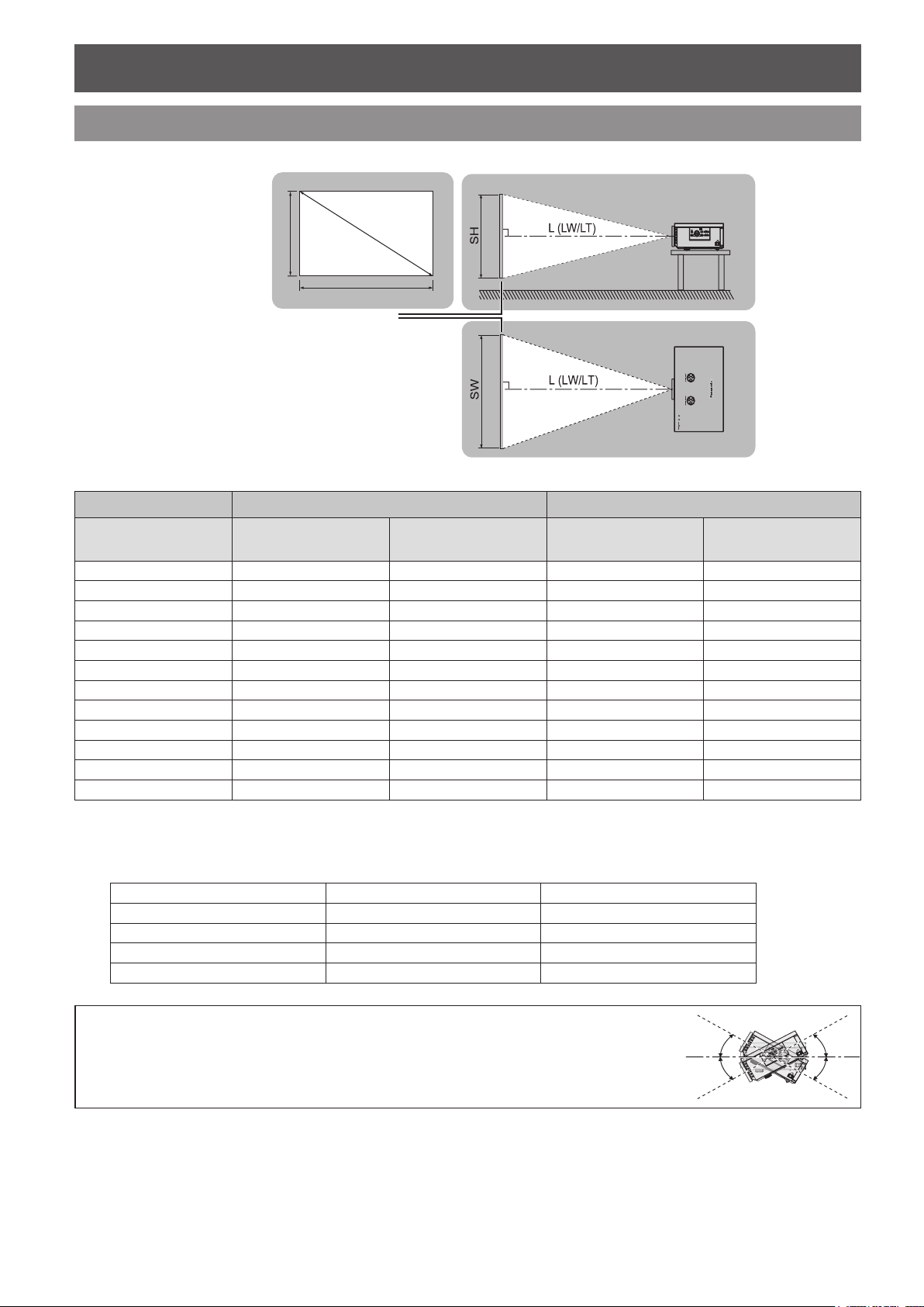
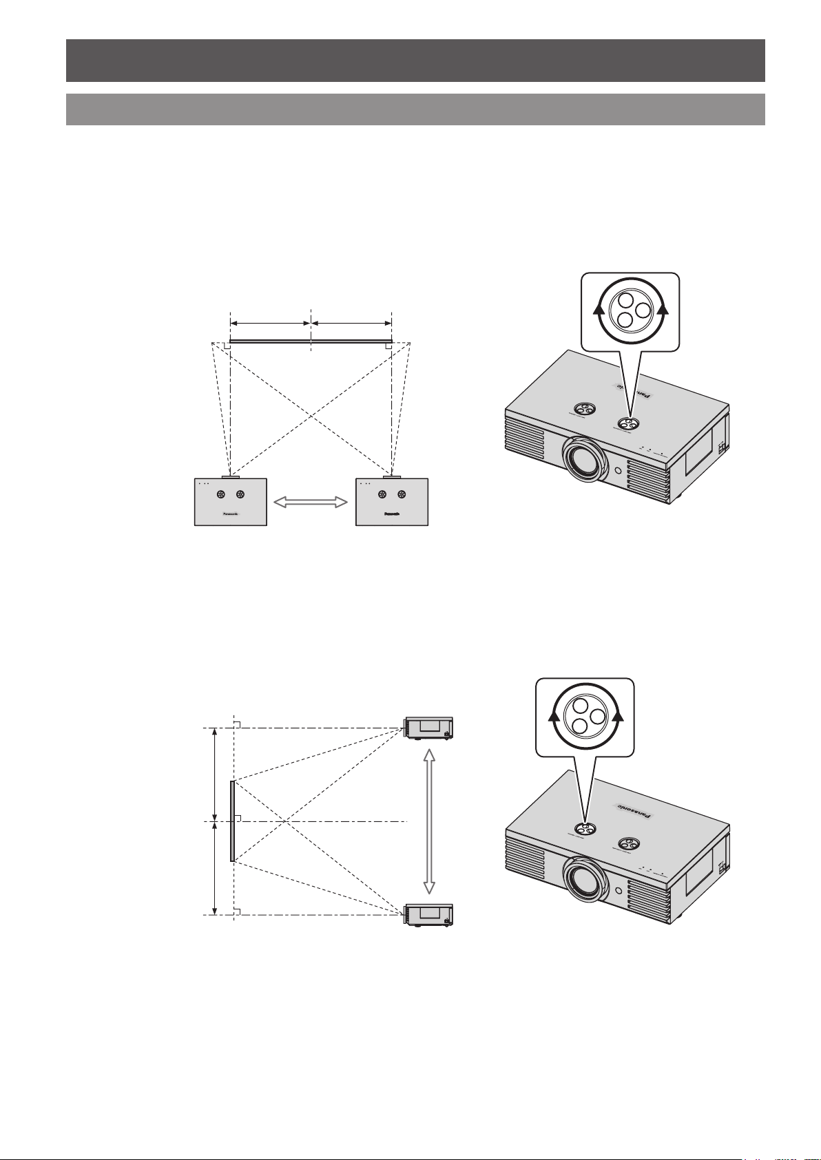
Screen size and throw distance
You can adjust the projection size with 2 × zoom lens. Calculate and dene the throw distance as follows.
All measurements and the calculation results below are approximate and may differ from the actual measurements.
Projected image
Screen Diagonal
(SD)
1.02 m (40") 1.2 m (3'11") 2.3 m (7'6") 1.3 m (4'3")
1.27 m (50") 1.5 m (4'11") 2.9 m (9'6") 1.6 m (5'3") 2.3 m (7'6")
1.52 m (60") 1.8 m (5'10") 3.5 m (11'5") 1.9 m (6'2") 2.8 m (9'2")
1.78 m (70") 2.1 m (6'10") 4.1 m (13'5") 2.2 m (7'2") 3.3 m (10'9")
2.03 m (80") 2.4 m (7'10") 4.7 m (15'5") 2.6 m (8'6") 3.8 m (12'5")
2.29 m (90") 2.7 m (8'10") 5.3 m (17'4") 2.9 m (9'6") 4.2 m (13'9")
2.54 m (100") 3.0 m (9'10") 5.9 m (19'4") 3.2 m (10'6") 4.7 m (15'5")
3.05 m (120") 3.6 m (11'9") 7.2 m (23'7") 3.8 m (12'5") 5.7 m (18'8")
3.81 m (150") 4.5 m (14'9") 9.0 m (29'6") 4.8 m (15'9") 7.1 m (23'3")
5.08 m (200") 6.0 m (19'8") 12.0 m (39'4") 6.4 m
6.35 m (250") 7.6 m (24'11") 15.0 m (49'2") 8.0 m (26'3") 12.0 m (39'4")
7.62 m (300") 9.1 m (29'10") 18.0 m (59') 9.6 m (31'6") 14.4 m (47'2")
When using both 2.35:1 and 16:9 aspect images onto a 2.35:1 sized screen.*1.
Minimum distance
(LW)
Screen
Throw distance (16:9) Throw distance (2.35:1)
Maximum distance
(LT)
Minimum distance
(LW)
*1
(21'0")
Maximum distance
(LT)
9.6 m (31'6")
J
Calculation methods for screen dimensions
You can calculate more detailed screen dimensions from the screen diagonal.
Screen height (SH) = SD (m) × 0.490 = SD (m) × 0.392
Screen width (SW) = SD (m) × 0.872 = SD (m) × 0.920
Minimum distance (LW) = SD (m) × 1.189 − 0.04 = SD (m) × 1.256 − 0.04
Maximum distance (LT) = SD (m) × 2.378 − 0.05 = SD (m) × 1.899 − 0.05
NOTE:
16:9 size 2.35:1 size
You can tilt the projector body less than approximately ±30 ° vertically and ±10 ° horizontally. •
Overtilting may result in shortening the component’s life.
Do not cover the air exhaust/intake ports or place anything within 50 cm (19 5/8") of them. •
+30 °
−30 °
Page 5
Setting up
E
NGLISH - 5
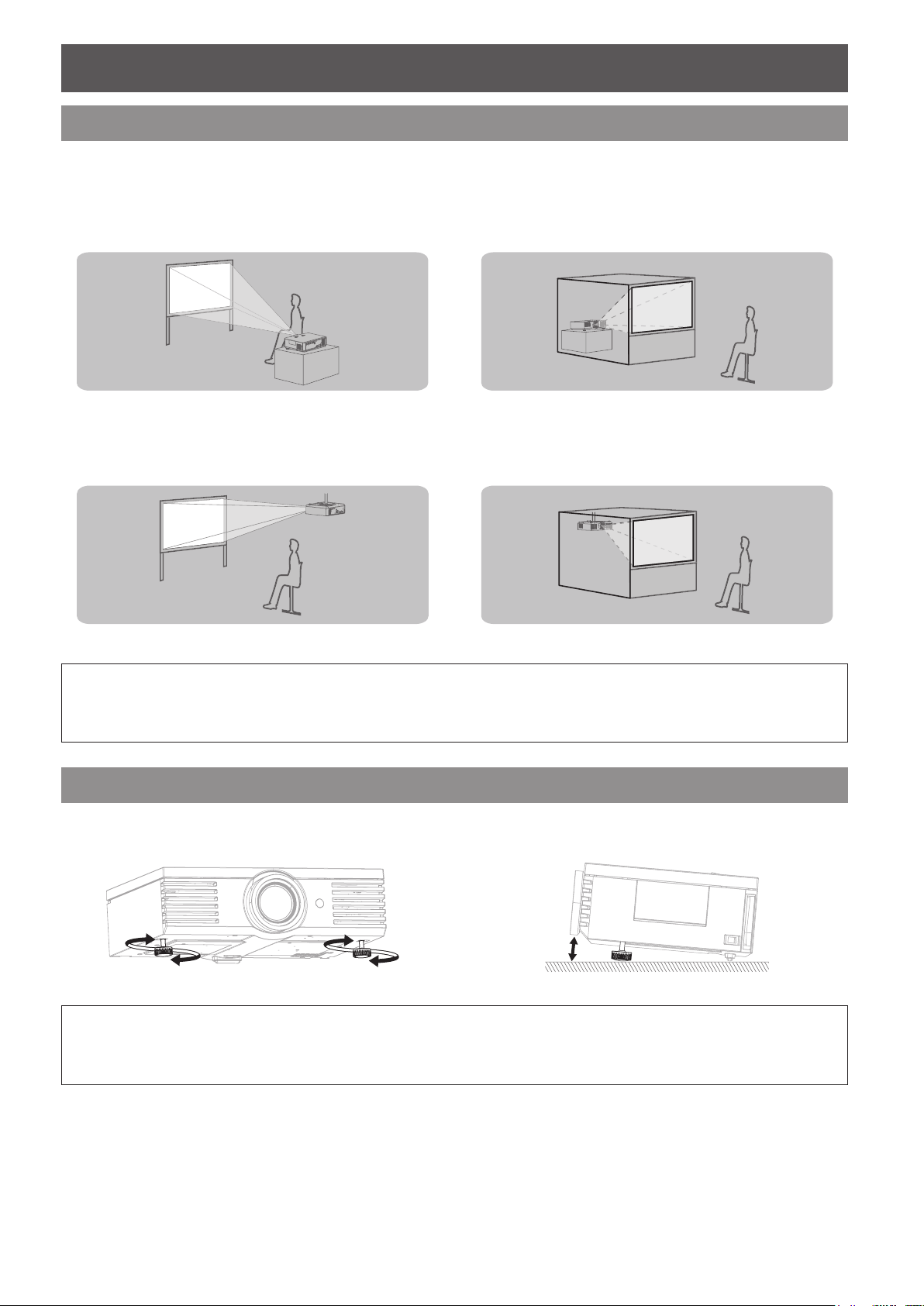
Projection method
You can use the projector with any of the following 4 projection methods. To set the projector in the desired
method, see “INSTALLATION” on page 39.
J
Setting on a desk/oor and
projecting from front
INSTALLATION: FRONT/DESK INSTALLATION: REAR/DESK
J
Mounting on the ceiling and
projecting from front
INSTALLATION: FRONT/CEILING INSTALLATION: REAR/CEILING
J
Setting on a desk/oor and
projecting from rear
J
Mounting on the ceiling and
projecting from rear
NOTE:
A translucent screen is required for rear projection. •
When mounting the projector on the ceiling, the optional ceiling mount bracket (ET-PKE2000, ET-PKE1000S) is required. •
See “Ceiling mount bracket safeguards” in “Technical Information” of the operating instructions. •
Front leg adjusters and throwing angle
You can screw up/down the front leg adjusters to control the angle of the projector for adjusting the throwing angle.
See “Positioning the image” on page 12.
NOTE:
Heated air comes out of the air exhaust port. Do not touch the air exhaust port directly. •
If keystone distortion occurs, see “KEYSTONE” on page • 34.
Screw up the front leg adjusters, and an audible click will be heard as the limit. •
Page 6
Setting up
6 - ENGLISH
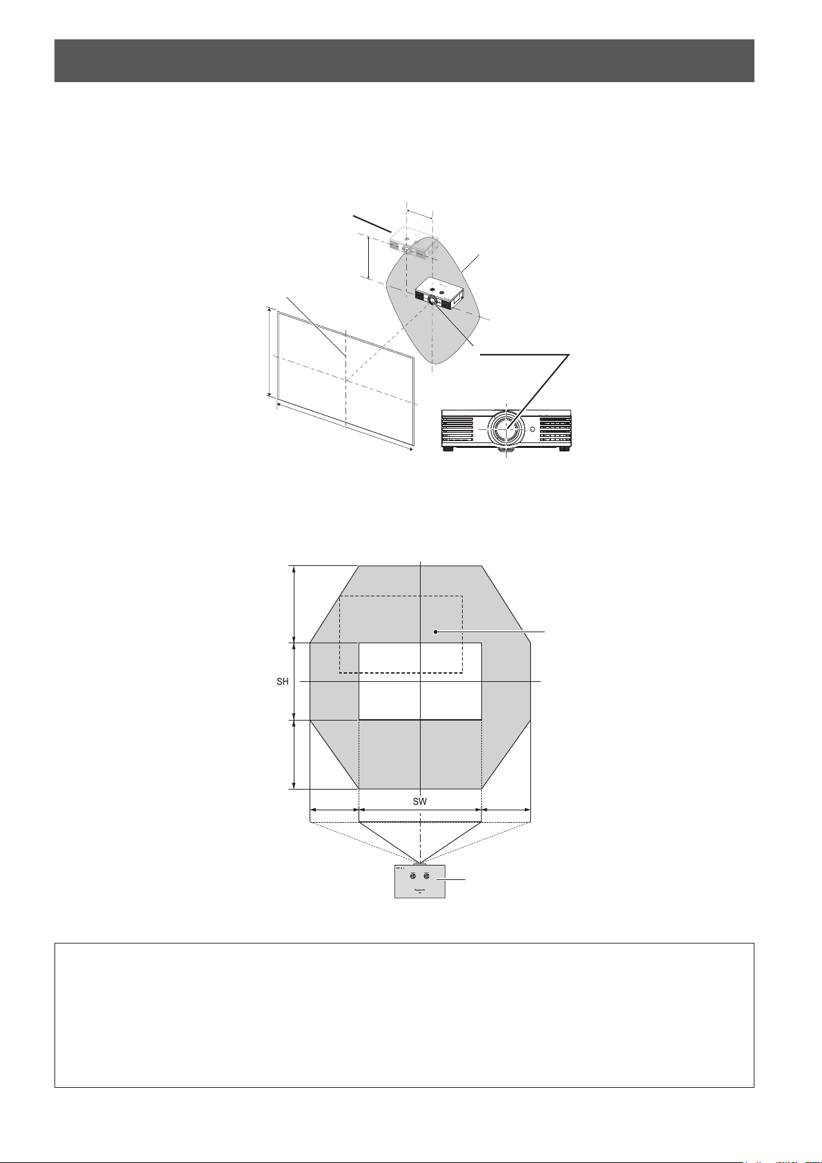
Lens shift and positioning
If the projector is not positioned right in front of the centre of the screen, you can adjust the projected image
position by moving the lens shift dials within the shift range of the lens.
J
Adjusting the lens shift dials
Q
Horizontal shift
You can place the projector where the projector lens is up to 40 % horizontally off-centre from the screen and
then adjust the image position with the Lens shift dial • Horizontal.
Up to about 40 %
of the projection
Turning the dial clockwise:
Image moves to the right
Q
Vertical shift
You can place the projector where the projector lens is up to 100 % vertically off-centre from the screen and
then adjust the image position with the Lens shift dial • Vertical.
Up to about 40 %
of the projection
Turning the dial counterclockwise:
Image moves to the left
Up to about 100 %
of the projection
Up to about 100 %
of the projection
Turning the dial counterclockwise:
Image moves to the bottom
Turning the dial clockwise:
Image moves to the top
Page 7
Setting up
E
NGLISH - 7
H
V
SH
SW
100 %
100 %
40 % 40 %
J
Projector location range
You can determine where to locate the screen and the projector by considering the lens shift possibilities.
Q
When the screen position is xed
Projector
Placement
Vertical centre of
screen
Centre of lens
Screen
Q
When the projector position is xed
Shift range
Projector
NOTE:
When the projector is located right in front of the centre of the screen and the lens shift dials is centred, you will get the •
best quality of the projection image.
When the • Lens shift dial • Vertical is at the vertical limit of the shift range, you cannot turn the dial to the horizontal limit,
likewise when the Lens shift dial • Horizontal is at the horizontal limit of the shift range, you cannot turn the dial to the
vertical limit.
When the projector is tilted and adjusting • KEYSTONE, the centre of the screen and the lens need to be realigned.
Do not force the lens shift dials to turn as this may damage the projector. Turning the dials maximum limit is 3 or 4 times •
from the default position.
Page 8
Connections
8 - ENGLISH
Connections
Before connecting to the projector
Read and follow the operating and connecting instructions of each peripheral device.
The peripheral devices must be turned off.
Use cables that match each peripheral device to be connected.
Conrm the type of video signals. See “List of compatible signals” in “Technical Information” of the operating
instructions.
Audio cables must be connected from each peripheral device directly to the audio reproduction system.
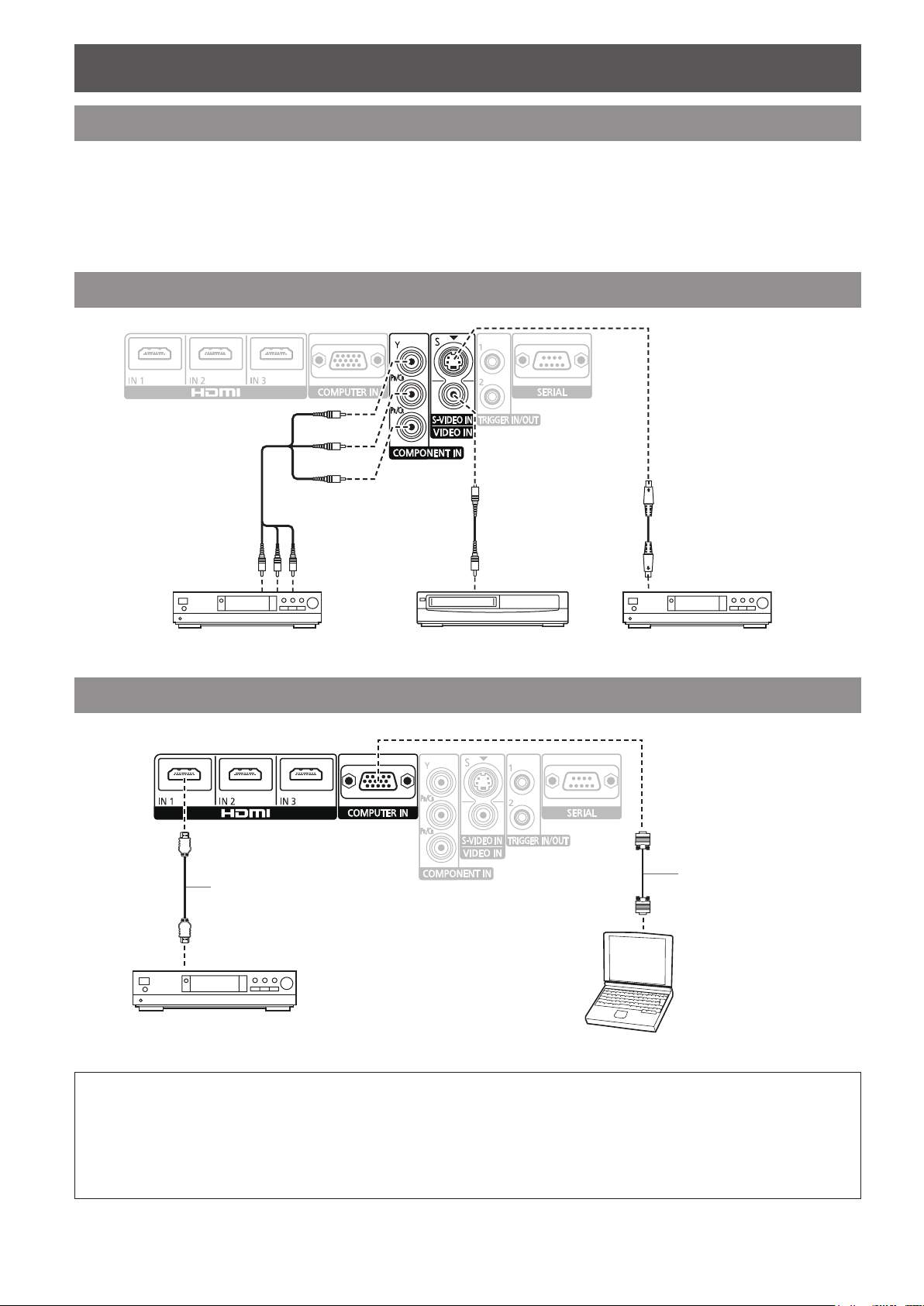
Connecting example: COMPONENT IN/S-VIDEO IN/VIDEO IN
To COMPONENT
video output
DVD player Video player DVD player
To VIDEO output To S-VIDEO output
Connecting example: HDMI IN/COMPUTER IN
HDMI cable
(Commercial item)
To HDMI output
RGB signal cable
(Commercial item)
NOTE:
Make sure the HDMI cable is adapted to your HDMI device for proper performance. •
A compatible cable is required for an HDMI 1 080p signal. •
It is possible to connect with DVI devices via a HDMI/DVI conversion adapter, but some equipment may not project the •
image properly or other problems could be encountered.
Please tighten securely, xing the screws on the connectors (D-SUB 15-pin) of the RGB signal cable. •
For more information about the serial terminals, see “Serial terminal” on page • 42.
Blu-ray player
Computer
Page 9
Switching the projector on/off
E
NGLISH - 9
Basic Operation
Switching the projector on/off
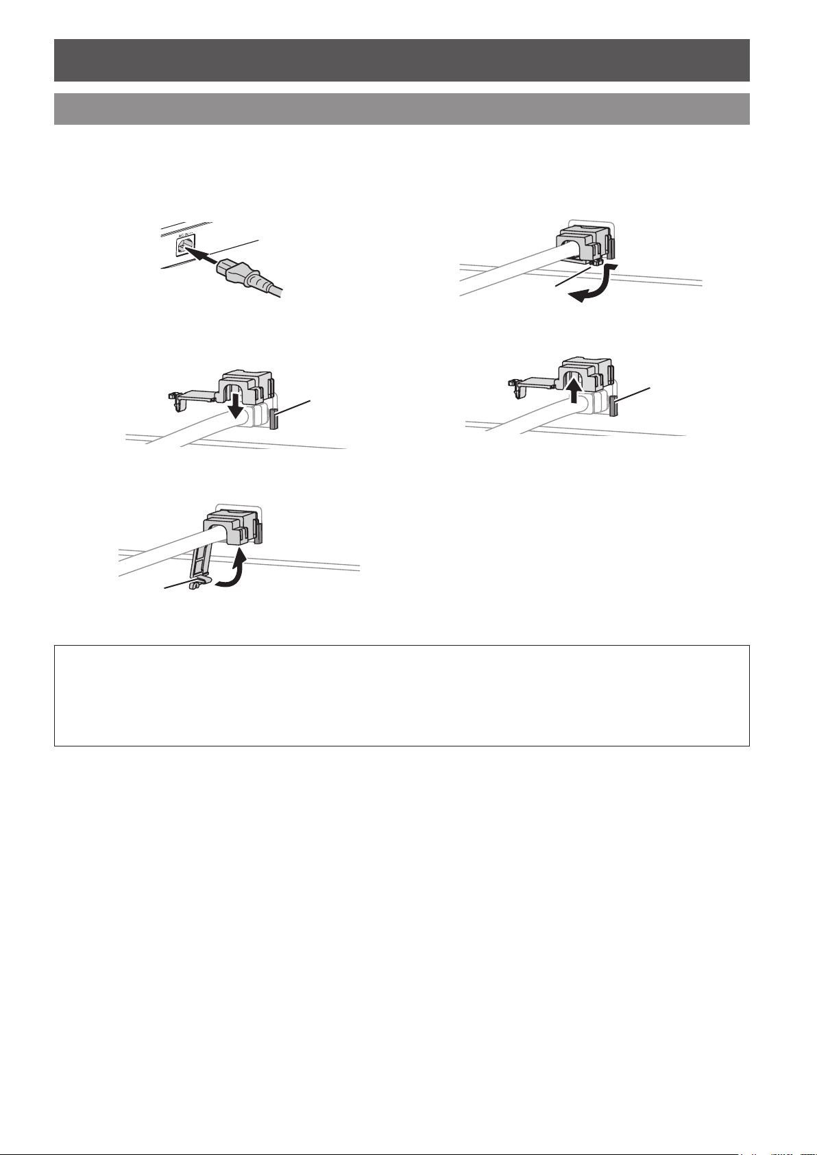
Mains lead
J
Connecting
Make sure the shape of the mains plug and the 1.
AC IN terminal on the back of the projector match,
then push the plug all the way in.
Align the side of the 2. power cord secure lock with
the side guide rail of the AC IN terminal of the
projector and slide it in.
Rail guide
Place the latch to the latch catcher and press until 3.
it clicks.
J
Disconnecting
Unplug the mains plug from the mains socket.1.
Depress the latch and slide the cover off.2.
Slide the power cord secure lock up along the side 3.
guide rail.
Hold the plug and unplug it from the 4. AC IN
terminal on the back of the projector.
Latch
Rail guide
Connect the mains plug to a mains socket.4.
NOTE:
Do not use other than the provided mains lead. •
Ensure all the input devices are connected and turned off before connecting the mains lead. •
Do not force the connector as this may damage the projector and/or the mains lead. •
Dirt or dust build-up around plugs may cause re or electrical hazards. •
Switch off the power to the projector when not in use. •
Latch
Page 10
Switching the projector on/off
10 - ENGLISH
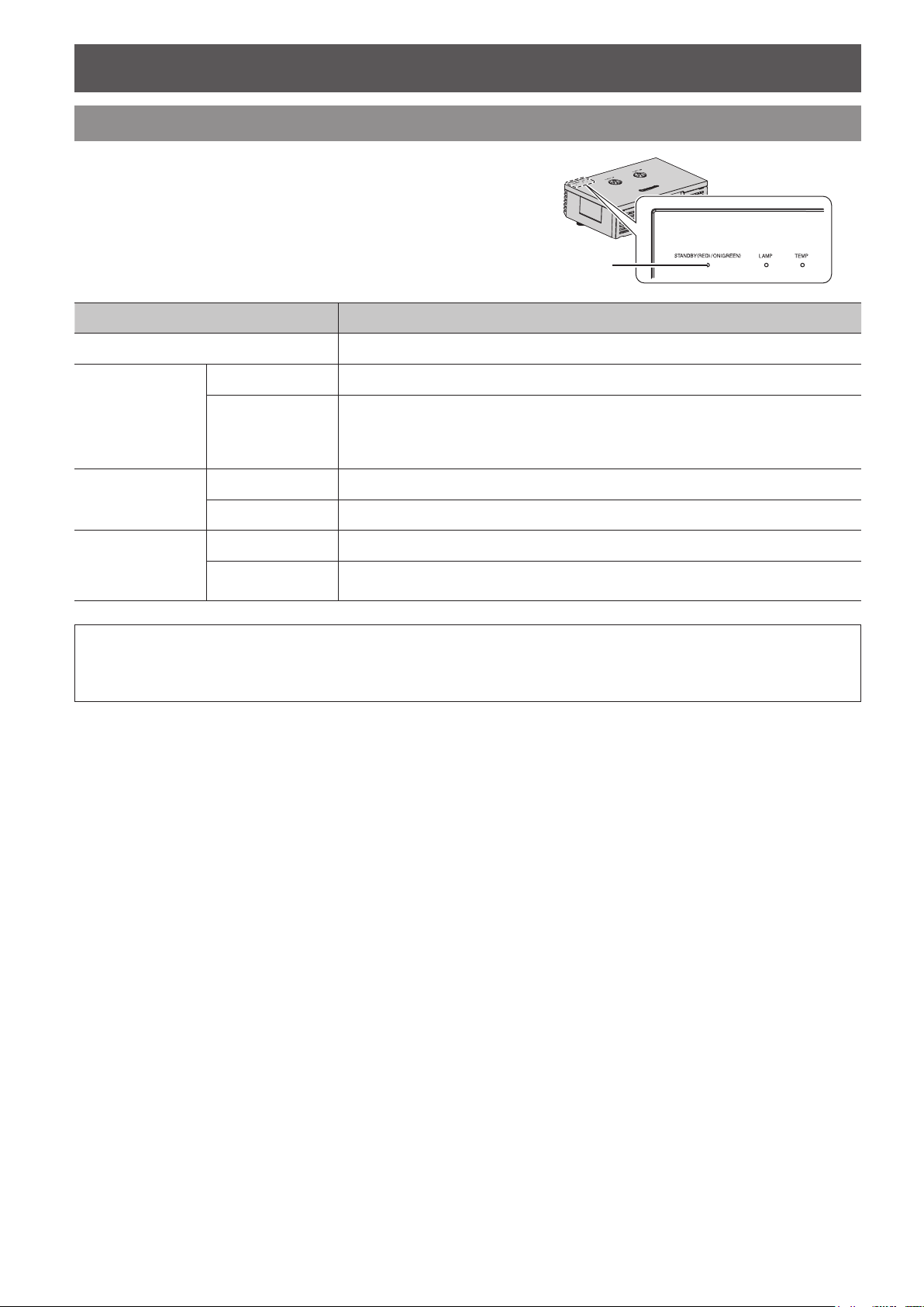
Power indicator
Power indicator informs you of the status of the power.
When the
indicator will turn red, and you cannot switch on the
power.
No illumination or ashing MAIN POWER is switched off.
TEMP indicator is ashing, the power
Indicator status Status
Lit MAIN POWER is switched on and the projector is in standby mode.
Power indicator
Red
Flashing
Flashing The power button is switched on and the projector is getting ready to project.
Green
Lit Projecting.
Lit The power button is switched off and the projector is cooling the lamp.
Orange
Flashing
MAIN POWER is switched on (standby mode) and the POWER ON LINK is set to
ON.
•
The power consumption is not much different when it is lit.
(See “VIERA Link Connection” on page 45)
The power button is switched on again when cooling the lamp and recovering to
projection mode. Recovery may take a while.
NOTE:
See “TEMP indicator” in “TEMP and LAMP Indicators” of the operating instructions. •
While the projector is cooling the lamp, do not switch • MAIN POWER off or unplug the mains lead.
The electric consumption in standby mode is 0.08 W. •
Page 11
Switching the projector on/off
E
NGLISH - 11
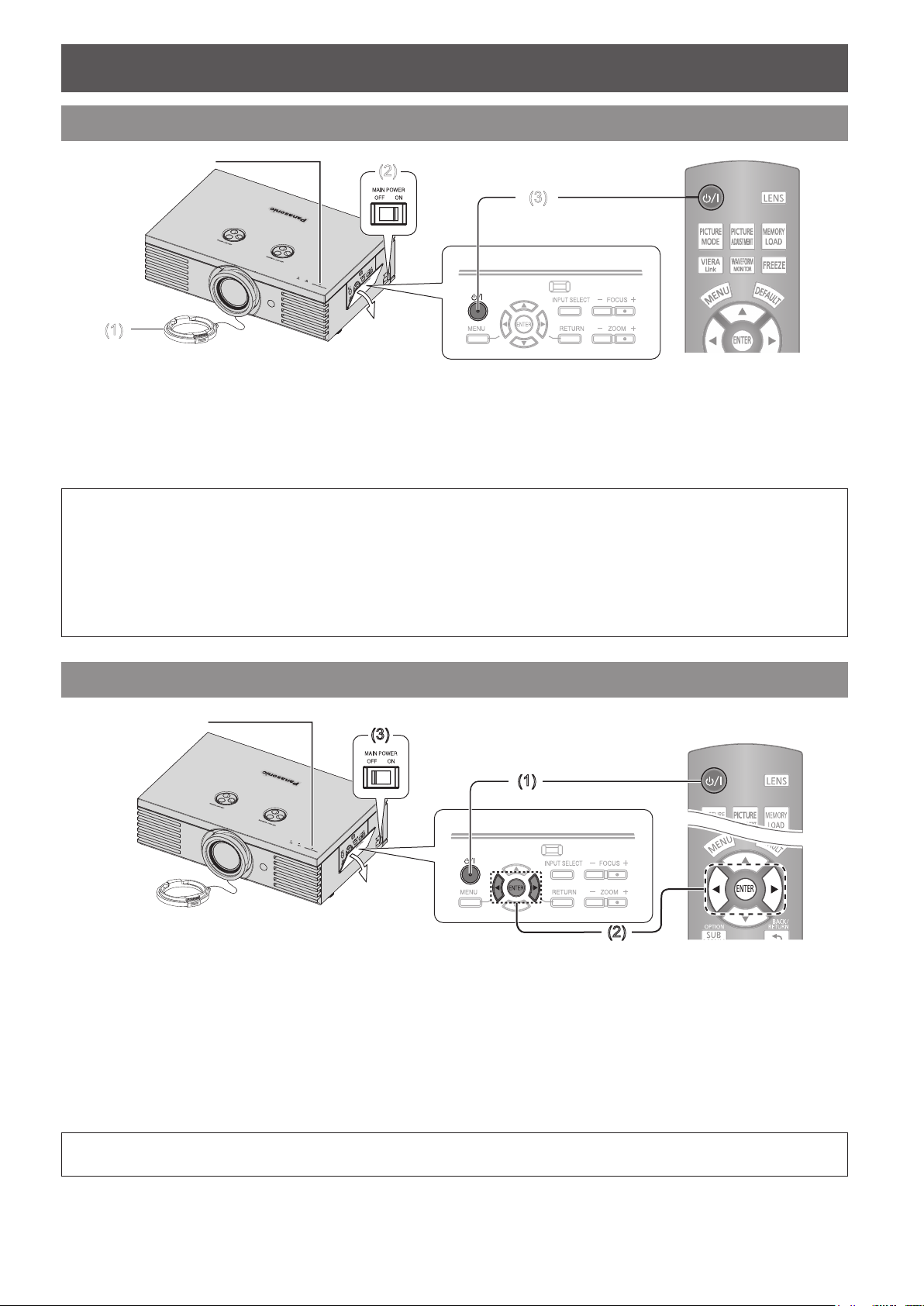
Switching on the projector
(2)
(3)
(1)
(3)
(1)
(2)
Power indicator
Remove the lens cover from the lens.1.
Switch 2. MAIN POWER on.
The power indicator lights up in red.
Press the power button.3.
The power indicator lights up in green after ashing
for a while.
The
STARTUP LOGO is displayed on the screen.
See “STARTUP LOGO” on page 39.
NOTE:
When the internal cooling fan is operating, some operational sound may be heard. The loudness of the operational •
sound depends on the external temperature.
You can reduce the operational sound by setting the • LAMP POWER in OPTION menu to the ECO-MODE. See “LAMP
POWER” on page 41.
When starting up the projector, some small rattling or tinkling sound may be heard, or the display may icker for the •
characteristics of the lamp. Those are normal and will not affect the performance of the projector.
Do not attempt to modify the lens cover which may cause burns, re or damage to the projector. •
Switching off the projector
Power indicator
Press the power button.1.
NOTE:
Press the power button twice or for a long duration to switch the power off. •
The conrmation screen is displayed.
To return to the projection, press the
RETURN button.
MENU or
Press the power or 2. ENTER button.
The power indicator lights up in orange while cooling
the lamp, then illuminates red when it is ready to
switch off MAIN POWER.
Switch off 3. MAIN POWER on the left side of the
projector.
Attach the lens cover.4.
Page 12
Projecting an image
12 - ENGLISH
Projecting an image
Selecting the input signal
Switch on the connected devices.1.
Press the play button of the required device.
Press the 2. INPUT SELECT button to select the
required input method if needed. See “Switching
the input signal” on page 15.
The image will be projected on the screen.
Positioning the image
NOTE:
AUTO SEARCH • is ON as default and the signal from
the connected devices is detected automatically. See
“AUTO SEARCH” on page 39.
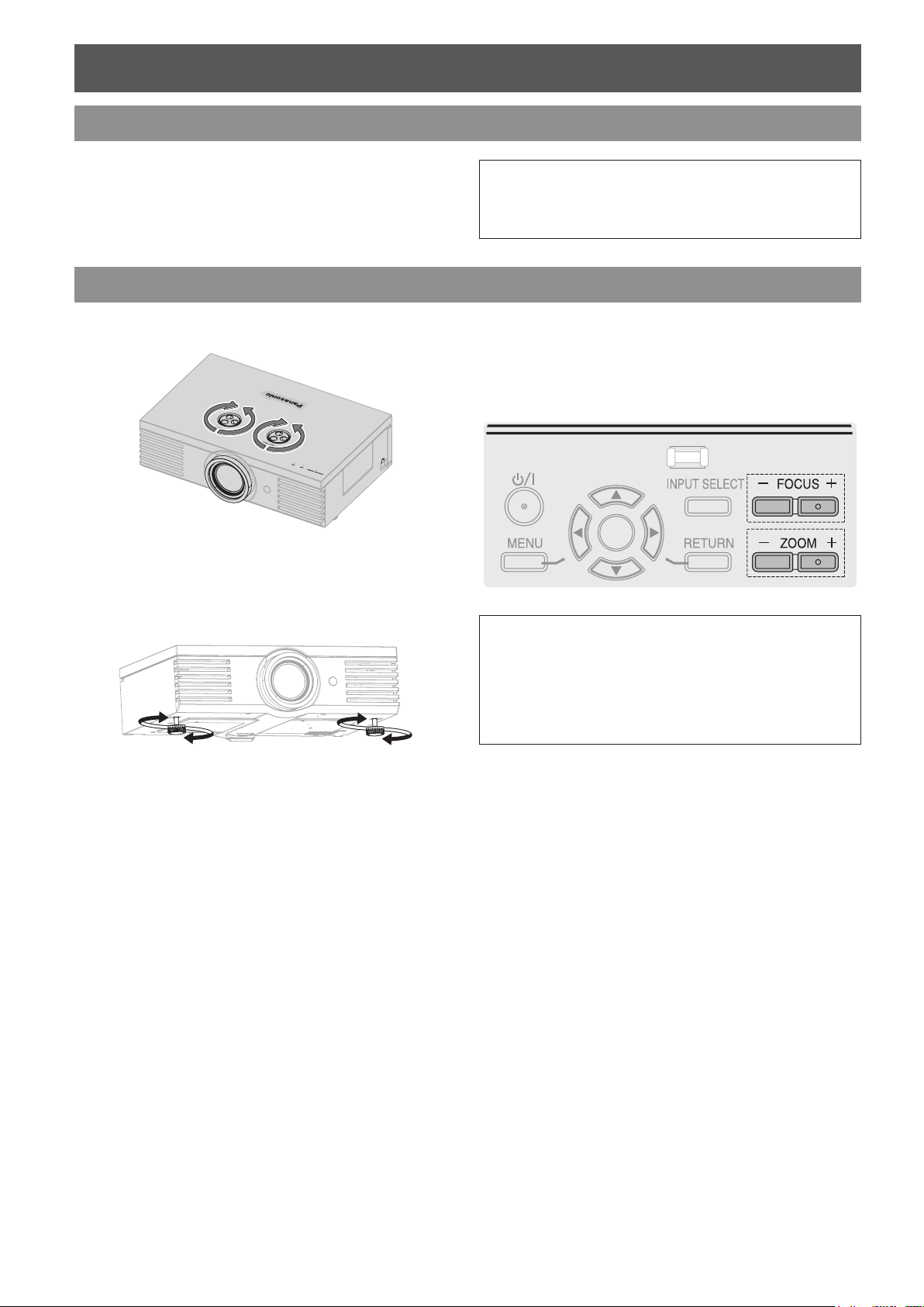
Adjust the projected image with the lens shift dials. 1.
See “Lens shift and positioning” on page 6.
Adjust the angle of the projector.2.
Screw the front leg adjusters up/down and adjust the
angle vertically.
See “Front leg adjusters and throwing angle” on
page 5.
Adjust the focus and the projected image size.3.
Press +/− of the
adjust.
Press the
by the remote control. See “LENS CONTROL” on
page 35.
FOCUS and ZOOM buttons to
LENS button to adjust the focus and zoom
NOTE:
Do not touch the air exhaust port as this may cause •
burns or injury.
If keystone distortion occurs, see “KEYSTONE” on •
page 34.
If you adjust the focus, you may need to adjust the size •
of the image by pressing the ZOOM button again.
Page 13
Remote control operation
E
NGLISH - 13
Remote control operation
Operating range
You can operate the projector with the remote control
within the remote range of 7 m (22'11").
Q
Facing to the projector
Ensure the remote control emitter is facing the
remote control signal receptor on the front of
the projector and press the required buttons to
operate.
Q
Facing to the screen
Ensure the remote control emitter is facing the
screen and press the required buttons to operate
the projector. The signal will be reected off the
screen. The operating range may differ due to the
screen material. This function may not be effective
with a translucent screen.
NOTE:
Do not let strong light shine onto the signal receptor. •
The remote control may malfunction under strong light
such as uorescent light.
If there are any obstacles between the remote control •
and the remote control signal receptor, the remote
control may not operate correctly.
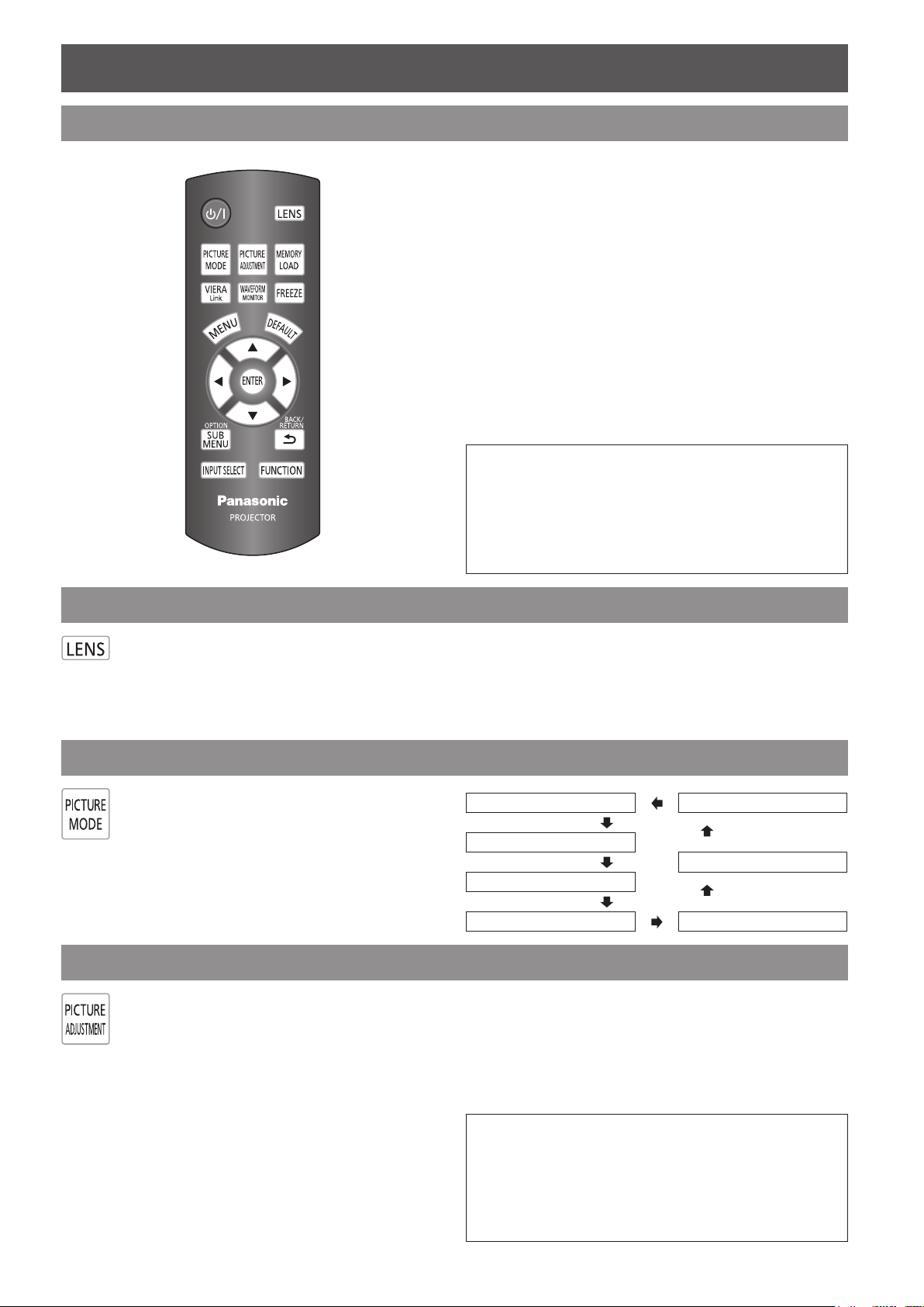
Managing the lens control settings
You can adjust the focus and zoom of the
projected image, and save the settings.
Press the LENS button once to display the
LENS CONTROL menu.
If you have saved Lens Memories, press the LENS
button twice to load the saved memories instantly. And
press the LENS button three times to go back to the
LENS CONTROL menu.
See “LENS CONTROL” on page 35.
Switching the picture mode
You can switch the preset picture mode settings
by pressing the PICTURE MODE button. Press
the button until the required setting is selected.
See “PICTURE MODE” on page 20.
Adjusting the image
You can display the PICTURE and ADVANCED
MENU menu items by pressing the PICTURE
ADJUSTMENT button. Press the button to
switch between PICTURE and ADVANCED
MENU menu.
Press ▲ ▼ to select the required menu item
and ◄ ► to adjust.
Q
PICTURE menu items
PICTURE MODE, CONTRAST, BRIGHTNESS,
COLOUR, TINT, SHARPNESS, COLOUR
TEMPERATURE and DYNAMIC IRIS
Q
ADVANCED MENU items
GAMMA ADJUSTMENT, CONTRAST R/G/B
BRIGHTNESS R/G/B, NR, MPEG NR
FRAME CREATION, COLOUR MANAGEMENT
x.v.Colour, DETAIL CLARITY, CINEMA REALITY
TV-SYSTEM
NOTE:
For each menu item description, see “PICTURE menu” •
on page 20.
The screen will be cleared after 7 seconds without any •
operation.
The • GAMMA setting is only available when the
GAMMA ADJUSTMENT is set to SIMPLE.
NORMAL CINEMA3
DYNAMIC
CINEMA2
COLOUR1
COLOUR2 CINEMA1
,
and
RGB/YPbPr
.
,
,
,
Page 14
Remote control operation
14 - ENGLISH
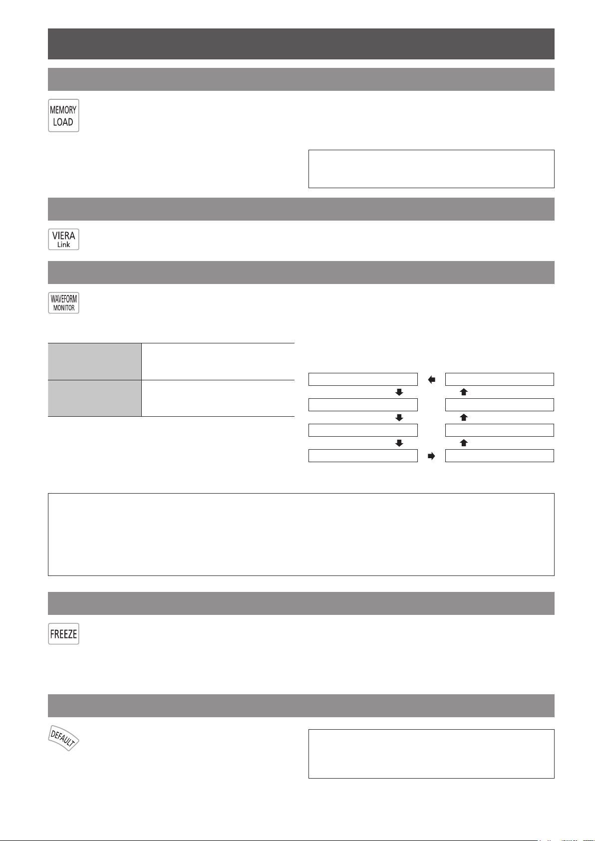
Loading a saved setting
You can access saved settings instantly. See
“MEMORY LOAD” on page 31.
Select the required setting from 1. MEMORY 1 - 16.
Undened setting will not be displayed.
Press the 2. ENTER button to activate the selected
setting.
NOTE:
If you have not saved any settings, • MEMORY 1 - 16
will not be displayed.
VIERA Link
You can control some functions of the connected equipment with this projector remote control.
See the operating instructions for more details.
Adjusting the signal condition with a waveform
You can display the image brightness and
contrast level of the input signal with a
waveform. See “WAVEFORM MONITOR” on
page 21.
FULL SCAN
SINGLE LINE SCAN
Monitoring the waveform of
brightness and contrast of the whole
image.
Monitoring the waveform of
brightness and contrast in each
horizontal line of the image.
Press the 2. ENTER button until the required
waveform option is displayed.
In
FULL SCAN mode, press ▲ ▼ ◄ ► to change
the waveform position.
In
SINGLE LINE SCAN mode, press ▲ ▼ to select
the required line position.
FULL SCAN(Y) SINGLE LINE SCAN(B)
FULL SCAN(R) SINGLE LINE SCAN(G)
J
Displaying the waveform
Press the 1. WAVEFORM MONITOR button and
display the waveform monitor.
Press the
escape from the waveform mode.
WAVEFORM MONITOR button again to
FULL SCAN(G) SINGLE LINE SCAN(R)
FULL SCAN(B) SINGLE LINE SCAN(Y)
NOTE:
In • SINGLE LINE SCAN mode, the position of the waveform monitor depends on the position of the selected line.
You can display the main menu by pressing the • MENU button and adjust the menu items.
The called up menu items displayed position depends on the position of the waveform monitor. •
You can activate • AUTO ADJUST of the WAVEFORM MONITOR menu by pressing the DEFAULT button.
The signal which is lower than 0 % in the waveform will be displayed as same as 0 % on the projected image. •
While the waveform is displayed, you can not adjust the • COLOUR MANAGEMENT settings.
Capturing an image
Press the FREEZE button to capture the
image, and you can see it as a still picture
while the AV equipment are still running. Press
the FREEZE button again to escape and return
to the continuing image.
While displaying the frozen image, you can enter the
AREA SELECT mode of the SPLIT ADJUST menu by
pressing the ENTER button. See “SPLIT ADJUST” on
page 22.
Resetting to the factory default settings
You can reset most of the customised
settings to the factory defaults by pressing
the DEFAULT button. Display the required
sub-menu or the menu items and press the
button.
NOTE:
Some menu items are not available to reset by •
pressing the DEFAULT button. Adjust each menu item
manually.
Page 15
Remote control operation
E
NGLISH - 15
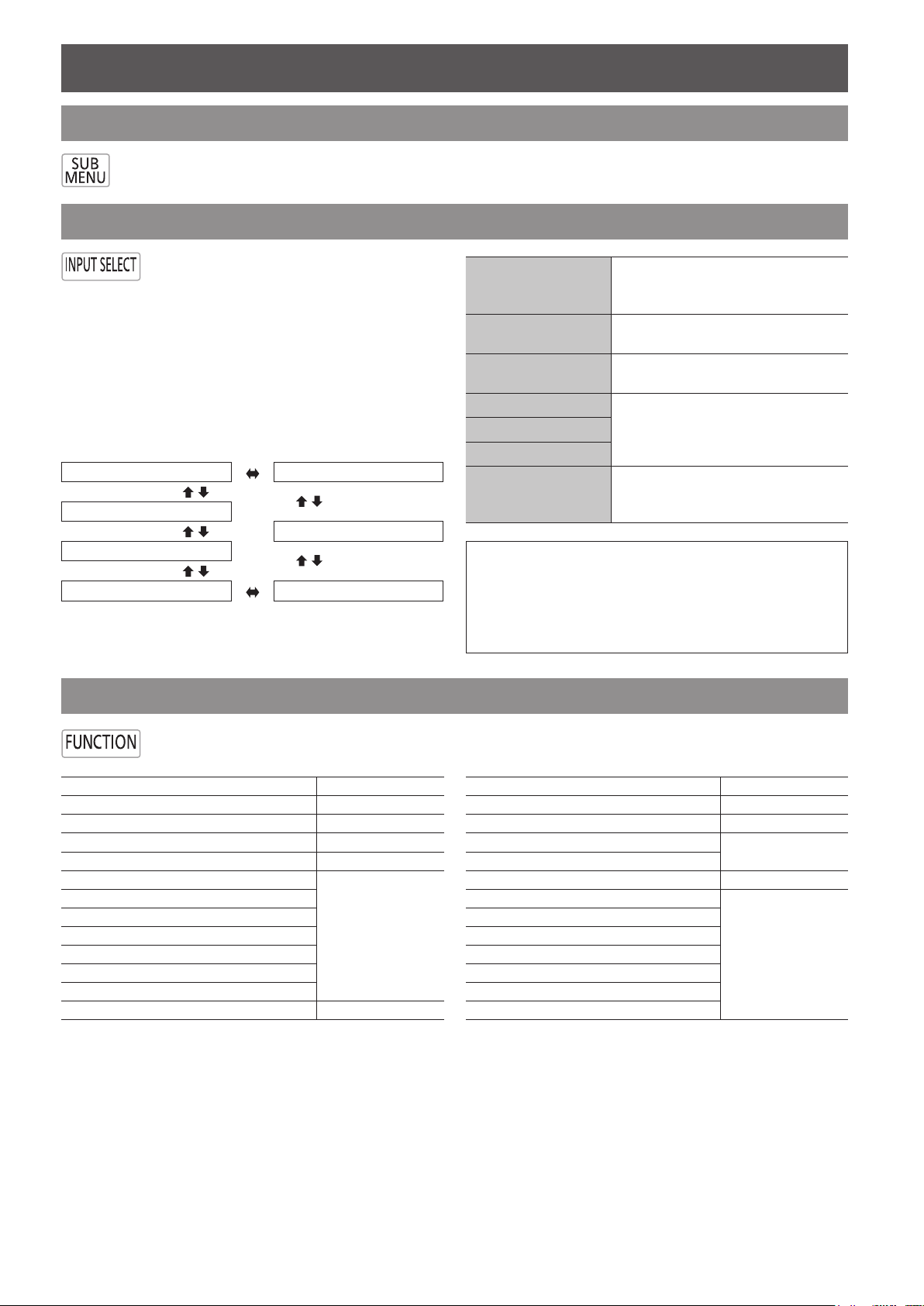
SUB MENU
You can command the connected equipment to display their sub menu.
It is used with the Link function (VIERA Link).
Switching the input signal
You can switch the input method manually
by pressing the INPUT SELECT button.
Press the button several times or press
COMPONENT IN
▲ ▼ ◄ ► to cycle through the input
methods as follows. The actual projected
S-VIDEO IN
image will be changed in a while.
The graphical guidance will be displayed on the upper
right of the projected image and you can conrm the
selected input method which is highlighted in yellow. See
“INPUT GUIDE” on page 39.
COMPONENT IN S-VIDEO IN
COMPUTER IN
VIDEO IN
HDMI 3 IN
HDMI 2 IN HDMI 1 IN
VIDEO IN
HDMI 1 IN
HDMI 2 IN
HDMI 3 IN
COMPUTER IN
NOTE:
If you select an unplugged input method, the guidance •
will blink on and off.
See “List of compatible signals” in “Technical •
Information” of the operating instructions.
See “Connections” on page • 8.
Using the assigned function as a shortcut
BPR
COMPONENT (YP
from the equipment connected to
COMPONENT IN.
S-VIDEO signal from the equipment
connected to S-VIDEO IN.
VIDEO signal from the equipment
connected to VIDEO IN.
HDMI signal from the equipment
connected to HDMI IN 1/HDMI IN 2/
HDMI IN 3.
RGB/YP
equipment connected to
COMPUTER IN.
BPR
signal from the
) signals
You can access the assigned function in FUNCTION BUTTON menu as a shortcut. See “FUNCTION
BUTTON” on page 38.
COLOUR MANAGEMENT page 27
GAMMA ADJUSTMENT page 23
SPLIT ADJUST page 22
WAVEFORM AUTO ADJUST page 21
FRAME CREATION page 26
NORMAL
DYNAMIC
COLOUR1
COLOUR2
CINEMA1
CINEMA2
CINEMA3
TEST PATTERN page 41
page 20
OPERATE OTHER DEVICE Booklet
ASPECT page 32
AUTO SETUP page 34
CONTRAST
BRIGHTNESS
BLANK page 38
HDMI 1 IN
HDMI 2 IN
HDMI 3 IN
COMPUTER IN
COMPONENT IN
S-VIDEO IN
VIDEO IN
page 20
page 15
Page 16

16 - ENGLISH
Settings
-
+
-
+
-
+
-
+
-
+
-
+
PICTURE MODE
CONTRAST
BRIGHTNESS
COLOUR
TINT
SHARPNESS
COLOUR TEMPERATURE
DYNAMIC IRIS
WAVEFORM MONITOR
SPLIT ADJUST
ADVANCED MENU
MEMORY SAVE
MEMORY LOAD
MEMORY EDIT
NORMAL
ON
0
0
0
0
0
0
PICTURE
POSITION
LANGUAGE
LENS CONTROL
FUNCTION BUTTON
VIERA LINK MENU
OPTION
ENTER
RETURN
SELECT
-
+
BRIGHTNESS
0
-
+
-
+
-
+
-
+
H-POSITION
V-POSITION
ASPECT
WSS
OVER SCAN
KEYSTONE
16:9
ON
0
0
+7
0
PICTURE
POSITION
LANGUAGE
LENS CONTROL
FUNCTION BUTTON
VIERA LINK MENU
OPTION
ENTER
RETURN
SELECT
-
+
-
+
-
+
-
+
H-POSITION
V-POSITION
ASPECT
WSS
OVER SCAN
KEYSTONE
16:9
ON
0
0
+7
0
PICTURE
POSITION
LANGUAGE
LENS CONTROL
FUNCTION BUTTON
VIERA LINK MENU
OPTION
ENTER
DEFAULT
RETURN
SELECT
-
+
BRIGHTNESS
0
Menu Navigation
Navigating through the MENU
J
Displaying the main menu
Press the MENU button to display the main
menu and the operating guidance.
Current
Main menu
Sub-menu
settings
Operating guidance
Contains the required buttons to adjust the settings.
J
Adjusting with the bar scale
items
The triangle mark under the bar indicates factory
default setting and the square indicates the current
.
setting
Current setting
J
Operating procedure
Press ▲ ▼ to scroll to the required main menu 1.
item and press the ENTER button to select.
The selected item is highlighted in orange and the
sub-menu is displayed on the right.
See “Menu list” on page
17.
Press ▲ ▼ to scroll to the required sub-menu item 2.
and press ◄ ► or the ENTER button to adjust.
The selected item is called up and the other menu
items disappear from the screen. The Called up item
will disappear after 5 seconds without any operation
and return to the menu mode.
If there is a lower level to the sub-menu item, the
next level will be displayed.
J
Returning to the previous menu
Press the MENU or RETURN button to return
to the previous menu. Press repeatedly to
escape from the menu mode and return to the
projection.
Default
Press ◄ ► to adjust or set the selected item.3.
For items using a bar scale, the current settings are
displayed on the left of the bar scale.
You can cycle through the options of an item by
pressing ▲ ▼.
Press the 4. MENU or RETURN button to return to
the previous menu.
Page 17

Menu Navigation
E
NGLISH - 17
Menu list
The menu options are structured and categorised. You can navigate through the menu with ▲ ▼ ◄ ► buttons.
NOTE:
The underlined items are factory default settings. •
Some default settings vary by the selected input signal. •
Sub-menu items vary according to the selected input signal. •
Some settings are adjustable without any signals. •
PICTURE
It is possible to adjust the picture quality.
PICTURE MODE page 20
NORMAL DYNAMIC
COLOUR1 COLOUR2
CINEMA1 CINEMA2
CINEMA3
CONTRAST page 20
(Default: 0)
BRIGHTNESS page 20
(Default: 0)
COLOUR page 20
(Default: 0)
TINT page 20
(Default: 0)
SHARPNESS
page 20
(Default: 0)
COLOUR TEMPERATURE
page 21
(Default: 0)
DYNAMIC IRIS
ON OFF
page 21
WAVEFORM MONITOR page 21
OFF
FULL SCAN(Y) FULL SCAN(R)
FULL SCAN(G) FULL SCAN(B)
SINGLE LINE SCAN(Y)
SINGLE LINE SCAN(R)
SINGLE LINE SCAN(G)
SINGLE LINE SCAN(B)
MONITOR POSITION
UPPER LEFT UPPER CENTRE
UPPER RIGHT LOWER LEFT
LOWER CENTRE LOWER RIGHT
AUTO ADJUST
START AUTO ADJUST
BLACK LEVEL ADJUST
WHITE LEVEL ADJUST
RGB ADJUST (BLACK)
RGB ADJUST (WHITE)
SPLIT ADJUST page 22
AREA SELECT
SPLIT ADJUST MODE
NORMAL REVERSE
▼
ADVANCED MENU page 23
GAMMA ADJUSTMENT
SIMPLE ADVANCED
NR
MPEG NR
FRAME CREATION
OFF MODE1
MODE2 MODE3
COLOUR MANAGEMENT
PROFILE ADJUSTMENT MODE
START ADJUSTMENT LOG
PROFILE SAVE PROFILE DELETE
PROFILE NAME CHANGE
ON OFF
CINEMA REALITY
ON OFF
TV-SYSTEM
AUTO
NTSC NTSC 4.43
PAL PAL-M
PAL-N SECAM
RGB/YPbPr
AUTO RGB YPbPr
CONTRAST R
CONTRAST G
CONTRAST B
BRIGHTNESS R
BRIGHTNESS G
BRIGHTNESS B
x.v.Colour
DETAIL CLARITY
MEMORY SAVE page 30
MEMORY 1 - 16
MEMORY LOAD page 31
MEMORY 1 - 16
MEMORY EDIT page 31
MEMORY DELETE
MEMORY 1 - 16 ALL DELETE
MEMORY NAME CHANGE
MEMORY 1 - 16
SIGNAL MODE page 31
▲
(Default: 0)
(Default: 0)
(Default: 0)
(Default: 0)
(Default: 0)
(Default: 0)
(Default: 0)
(Default: 0)
(Default: 3)
Page 18

Menu Navigation
18 - ENGLISH
POSITION
It is possible to adjust the image size and position.
H-POSITION page 32
(Default: 0)
V-POSITION page 32
(Default: 0)
DOT CLOCK page 32
(Default: 0)
CLOCK PHASE page 32
(Default: 0)
ASPECT page 32
4:3 16:9 s16:9 14:9
ZOOM ZOOM1 ZOOM2 JUST
AUTO H-FIT V-FIT
WSS page 34
ON OFF
OVER SCAN page 34
KEYSTONE page 34
(Default: 0)
AUTO SETUP page 34
LANGUAGE
It is possible to change the display language.
▲
H-AREA POSITION page 37
(Default: 0)
V-AREA POSITION page 37
(Default: 0)
LEFT MASKING AREA page 37
(Default: 0)
RIGHT MASKING AREA page 37
(Default: 0)
UPPER MASKING AREA page 37
(Default: 0)
LOWER MASKING AREA page 37
(Default: 0)
FUNCTION BUTTON
It is possible to assign a useful function to the
FUNCTION
COLOUR MANAGEMENT
GAMMA ADJUSTMENT
SPLIT ADJUST
WAVEFORM AUTO ADJUST
FRAME CREATION
NORMAL DYNAMIC
COLOUR1 COLOUR2
CINEMA1 CINEMA2
CINEMA3 TEST PATTERN
OPERATE OTHER DEVICE
ASPECT AUTO SETUP
CONTRAST BRIGHTNESS
BLANK HDMI 1 IN
HDMI 2 IN HDMI 3 IN
COMPUTER IN COMPONENT IN
S-VIDEO IN VIDEO IN
button.
page 38
LENS CONTROL
It is possible to adjust the lens position.
ZOOM/FOCUS page 35
LENS MEMORY LOAD page 35
LENS MEMORY 1 - 6
LENS MEMORY SAVE page 35
LENS MEMORY 1 - 6
LENS MEMORY EDIT page 36
LENS MEMORY DELETE
LENS MEMORY 1 - 6 ALL DELETE
LENS MEMORY NAME CHANGE
LENS MEMORY 1 - 6
AUTO SWITCHING page 36
2.35:1 IMAGE DETECTION
OFF LENS MEMORY 1 - 6
16:9 IMAGE DETECTION
OFF LENS MEMORY 1 - 6
▼
VIERA LINK MENU
It is possible to link with the connected equipment.
VIERA LINK CONTROL Booklet
RECORDER 1 - 3
PLAYER 1 - 3
HOME CINEMA 1 - 3
VIDEO CAMERA 1 - 3
LUMIX 1 - 3
OTHER 1 - 4
HOME CINEMA VOLUME Booklet
HOME CINEMA MUTE Booklet
OPERATE OTHER DEVICE
Booklet
Page 19

Menu Navigation
E
NGLISH - 19
OPTION
It is possible to change the option settings.
INPUT GUIDE page 39
DETAILED OFF
SIMPLE
OSD DESIGN page 39
TYPE1 TYPE2
TYPE3
OSD POSITION page 39
CENTRE LOWER LEFT
LOWER CENTRE LOWER RIGHT
UPPER LEFT UPPER CENTRE
UPPER RIGHT
BACK COLOUR page 39
BLUE BLACK
STARTUP LOGO page 39
ON OFF
AUTO SEARCH page 39
ON OFF
HDMI SIGNAL LEVEL page 39
NORMAL EXPAND
FRAME RESPONSE page 39
NORMAL FAST
INSTALLATION page 39
FRONT/DESK FRONT/CEILING
REAR/DESK REAR/CEILING
TRIGGER 1/2 SETTING page 40
OFF
OUTPUT
POWER ON
SELECT LENS MEMORY 1 - 6
BLANK
SELECT 4:3 ASPECT
SELECT 16:9 ASPECT
SELECT S16:9 ASPECT
SELECT JUST ASPECT
SELECT ZOOM ASPECT
SELECT H-FIT ASPECT
SELECT V-FIT ASPECT
RS-232C COMMAND LINK
▼
▲
DELAY TIME
0 SEC. 2 SEC. 4 SEC. 6 SEC.
8 SEC. 10 SEC. 20 SEC. 30 SEC.
INPUT
POWER ON/OFF BLANK
SLEEP page 41
OFF 60 MIN. 90 MIN. 120 MIN.
150 MIN. 180 MIN. 210 MIN. 240 MIN.
HIGH ALTITUDE MODE page 41
OFF ON
LAMP POWER page 41
NORMAL ECO-MODE
VIERA LINK SETTINGS page 41
VIERA LINK
ON OFF
POWER ON LINK
OFF ON
POWER OFF LINK
ON OFF
STANDBY POWER SAVE
OFF ON
INTELLIGENT AUTO STANDBY
OFF ON (WITH REMINDER)
ON (NO REMINDER)
VERSION
TEST PATTERN page 41
LAMP RUNTIME page 41
Page 20

20 - ENGLISH
PICTURE menu
Remote control Control panel
See “Navigating through the MENU” on page
See “Menu list” on page
17.
16.
PICTURE MODE
Depending on the projection environment, you can
use these preset parameter settings to optimise image
projection. Press ◄ ► to cycle through the options.
NORMAL CINEMA3
DYNAMIC
CINEMA2
COLOUR1
COLOUR2 CINEMA1
CONTRAST
You can adjust the contrast of the projected image.
Adjust the BRIGHTNESS in advance if necessary.
Lower Higher
Setting range: −64 to +64
BRIGHTNESS
You can adjust the brightness of the projected image.
Darker Brighter
Setting range: −32 to +32
COLOUR
You can adjust the colour saturation of the projected
image.
Setting for a general image,
NORMAL
DYNAMIC Bright and sharp setting.
COLOUR1
COLOUR2
CINEMA1
CINEMA2
CINEMA3 Vivid and crisp colour setting.
such as sports programme or TV
games.
Setting for HDTV standard
in ITU-R BT. 709 and colour
temperature 6 500 K at the default
setting of the PICTURE menu
items.
Setting for DCDM standard
(SMPTE431-2) and colour
temperature 6 300 K at the default
setting of the PICTURE menu
items.
Setting tuned by top Hollywood
colourists.
Deeper and more rich colour
setting
NOTE:
It may take a while until the selected mode is stabilised. •
Lighter Darker
Setting range: −32 to +32
When
RGB/YP
with the following signals.
1 125 (1 080)/60i 1 125 (1 080)/50i
1 125 (1 080)/60p 1 125 (1 080)/50i
BPR
signal is connected, only available
TINT
You can adjust the skin tone in the projected image.
More
reddish
Setting range: −32 to +32
When
COMPUTER signal is connected, only available
with the following signals.
1 125 (1 080)/60i 1 125 (1 080)/50i
1 125 (1 080)/60p 1 125 (1 080)/50i
More
greenish
SHARPNESS
You can adjust the sharpness of the projected image.
Less
sharp
Setting range will vary according to the selected input
signal.
More
sharp
Page 21

PICTURE menu
E
NGLISH - 21
COLOUR TEMPERATURE
OFF
FULL SCAN(Y)
FULL SCAN(R)
FULL SCAN(G)
FULL SCAN(B)
SINGLE LINE SCAN(Y)
SINGLE LINE SCAN(R)
SINGLE LINE SCAN(G)
SINGLE LINE SCAN(B)
MONITOR POSITION
UPPER LEFT
AUTO ADJUST
100%
50%
0%
100%
5
0%
0%
100%
50%
0%
ENTER
ENTER
You can adjust the white balance of the projected image.
Less
bluish
Setting range: −6 to +6
More
bluish
DYNAMIC IRIS
You can switch automatic adjustment of the lamp and
the lens iris on/off.
ON:
OFF:
Automatic adjustment
No adjustment
WAVEFORM MONITOR
You can monitor whether or not the luminance level
of the input signal is in the recommended range by
displaying it in the waveform monitor. If the waveform
is not in the recommended range, adjust it for the
best quality. See “Adjusting the signal condition with a
waveform” on page 14.
J
AUTO ADJUST
You can switch on/off the automatic adjustment
system in each item.
BLACK LEVEL ADJUST
Adjust the black level of luminance (Y) to 0 %.
WHITE LEVEL ADJUST
Adjust the white level of luminance (Y) to
100 %.
RGB ADJUST (BLACK)
Adjust the black level of colours (R/G/B) to 0 %.
RGB ADJUST (WHITE)
Adjust the white level of colours (R/G/B) to
100 %.
Press ▲ ▼ and select the required item.1.
Press ◄ ► and switch on/off.2.
Press ▲ ▼ and select 3. START AUTO ADJUST
and press the ENTER button.
The conrmation screen will be displayed.
Press ◄ ► and select 4. OK.
Press the 5. ENTER button.
J
Adjustment example
Project a commercial test signal for picture
adjustment on the screen and press the
WAVEFORM MONITOR button.
ON
ON
OFF
OFF
NOTE:
J
Press ▲ ▼ to move to the required waveform 1.
style.
Press the2. ENTER button to select.
The
WAVEFORM MONITOR will be displayed.
When the • WAVEFORM MONITOR is set to OFF, the
AUTO ADJUST is not displayed.
The waveform of the • WAVEFORM MONITOR will
not be displayed correctly with a noisy equipment or
source.
The • WAVEFORM MONITOR adjusts the signal level
based on the reference signal which consists of 0 %
and 100 %. The over scanned reference signal which
runs off the edge of the screen, below 0 % or over
100 % signal level will not be adjusted correctly.
MONITOR POSITION
When the FULL SCAN is selected, press ▲ ▼ ◄
► to adjust the position of the monitor.
See “Adjusting the signal condition with a waveform”
on page 14.
Signal levelSignal level
Adjust to 0 %
With
COMPUTER (except HD) or
HDMI (Expand)
Adjust to 0 %
Adjust to 100 %
displayable area
Monitor position
Adjust to 100 %
displayable area
Monitor position
Image
Image
Page 22

PICTURE menu
22 - ENGLISH
MOVE AREA GO TO SPLIT ADJUSTENTERGO TO FREEZE SCREENRETURN
MOVE AREA GO TO SPLIT ADJUSTENTERGO TO FREEZE SCREENRETURN
MOVE AREA GO TO SPLIT ADJUSTENTERGO TO FREEZE SCREENRETURN
Q
Adjusting with luminance options
Press the 1. ENTER button several times to display
FULL SCAN(Y)/SINGLE LINE SCAN(Y).
In
SINGLE LINE SCAN mode, select the required
adjusting point by pressing ▲ ▼.
Press the 2. PICTURE ADJUSTMENT button and
display the BRIGHTNESS by pressing ▲ ▼.
When
ADVANCED MENU is displayed, press the
button again to switch to the PICTURE menu.
Adjust by pressing ◄ ►.3.
Adjust the bottom line of the waveform to 0 % (0 or
7.5 IRE).
Setting range: −32 to +32
Press ▲ ▼ to display the 4. CONTRAST.
Adjust by pressing ◄ ►.5.
Adjust the up line of the waveform to 100 %
(100 IRE).
Setting range: −64 to +64
FULL SCAN(Y)/SINGLE LINE SCAN(Y)
BRIGHTNESS
CONTRAST
Adjust the bottom line of the
waveform to 0 % (0 or 7.5 IRE)
Adjust the top line of the waveform
to 100 % (100 IRE)
SPLIT ADJUST
You can perform image adjustment for some PICTURE
menu items while displaying a certain area of the frozen
image in a split window.
Q
SPLIT ADJUST MODE
Select the required split style from NORMAL and
REVERSE in the SPLIT ADJUST MODE menu.
NORMAL
REVERSE
Q
Adjusting with RGB options
Press the 1. ENTER button several times to display
the required R/G/B waveform option.
In
SINGLE LINE SCAN mode, select the required
adjusting point by pressing ▲ ▼.
Press the 2. PICTURE ADJUSTMENT button and
display the BRIGHTNESS R/BRIGHTNESS G/
BRIGHTNESS B by pressing ▲ ▼.
When
PICTURE menu is displayed, press the button
again to switch to the ADVANCED MENU.
Adjust by pressing ◄ ►.3.
Adjust the bottom line of the waveform to 0 % (0 or
7.5 IRE).
Setting range: −16 to +16
Press ▲ ▼ to display the 4. CONTRAST R/
CONTRAST G/CONTRAST B.
Adjust by pressing ◄ ►.5.
Adjust the up line of the waveform to 100 %
(100 IRE).
Setting range: −32 to +32
FULL SCAN(R)/SINGLE LINE SCAN(R)
BRIGHTNESS R
CONTRAST R
FULL SCAN(G)/SINGLE LINE SCAN(G)
BRIGHTNESS G
CONTRAST G
FULL SCAN(B)/SINGLE LINE SCAN(B)
BRIGHTNESS B
CONTRAST B
Adjust the bottom line of the
waveform to 0 % (0 or 7.5 IRE)
Adjust the top line of the waveform
to 100 % (100 IRE)
Adjust the bottom line of the
waveform to 0 % (0 or 7.5 IRE)
Adjust the top line of the waveform
to 100 % (100 IRE)
Adjust the bottom line of the
waveform to 0 % (0 or 7.5 IRE)
Adjust the top line of the waveform
to 100 % (100 IRE)
Q
Adjusting the image in a split window
Select 1. AREA SELECT and press the ENTER
button.
The image will be frozen and the area cursor will be
displayed.
Press ◄ ► to move the area cursor to select the 2.
area of interest and press the ENTER button.
The selected frozen image will be displayed in a split
window.
Page 23

PICTURE menu
E
NGLISH - 23
-
+
-
+
-
+
-
+
-
+
-
+
PICTURE MODE
CONTRAST
BRIGHTNESS
COLOUR
TINT
SHARPNESS
COLOUR TEMPERATURE
DYNAMIC IRIS
WAVEFORM MONITOR
SPLIT ADJUST
ADVANCED MENU
MEMORY SAVE
MEMORY LOAD
MEMORY EDIT
NORMAL
ON
0
0
0
0
0
0
PICTURE
POSITION
LANGUAGE
LENS CONTROL
FUNCTION BUTTON
VIERA LINK MENU
OPTION
ENTER
RETURN
SELECT
PT-AE4000E
MOVE AREA GO TO SPLIT ADJUSTENTERGO TO FREEZE SCREENRETURN
GAMMA ADJUSTMENT
CONTRAST R
CONTRAST G
CONTRAST B
BRIGHTNESS R
BRIGHTNESS G
BRIGHTNESS B
ADVANCED MENU
ADVANCED
0
0
0
0
0
0
ADJUSTMENT MODE
GAMMA HIGH
GAMMA MID
GAMMA LOW
POINT
Y ADJUST
R ADJUST
G ADJUST
B ADJUST
INITIALIZE
ADVANCED
5
GAMMA ADJUSTMENT
RETURN
SELECT
CHANGE MODE
RESET
RETURN
CHANGE POINT
OUTPUT ADJ.
INTPUT ADJ.
Y ADJUST
POINTINPUT
0% 50%
50%0
5
100%
INPUT
OUTPUT
OUTPUT
Press the 3. MENU button to display the PICTURE
menu on the right.
Adjust the required 4. PICTURE menu items.
Only the highlighted menu items are adjustable.
Sub-menu items vary according to the selected input
signal. See “Menu list” on page 17.
Press the 5. MENU or RETURN button several times
to escape from the menu.
Press the 6. ENTER button.
The conrmation screen will be displayed. Select
YES to nish the adjustment.
Press the 7. ENTER button.
Press the
AREA SELECT.
Press the
ADJUST mode.
ENTER button again to return to the
RETURN button to escape from the SPLIT
Q
Setting the GAMMA with the
ADVANCED mode
The 1. GAMMA ADJUSTMENT menu will be
displayed and press ◄ ► to select ADVANCED.
To open the 2. Y ADJUST menu, press ▲ ▼ to
select Y ADJUST and then press the ENTER
button.
In the graph below
Maximum 9 points are adjustable.
The point counts from lower input signal, 1 to 9.
Presents selected point
ADVANCED MENU
You can perform more detailed image adjustment
manually.
J
NOTE:
GAMMA
You can make detailed adjustments to the light
intensity of each input signal level by using the
ADVANCED mode or using the SIMPLE mode to
adjust at 3 levels (high, mid, low).
You can only adjust the • GAMMA settings through
either the ADVANCED or SIMPLE mode.
Both settings cannot be used at the same time.
Select GAMMA ADJUSTMENT in ADVANCED
MENU, and press ◄ ► or the ENTER button.
Information about the present selected point.
The factory default setting:
POINT [5] INPUT [50 %] OUTPUT [0]
Display the present selected point number.
POINT
Your selected point is indicated in yellow on
the graph.
(The factory default setting: point 5)
Display the input level of the present
selected point.
INPUT
Setting range: from 1 to 99 % in increments
of 1 %
(The factory default setting: 10, 20, 30, 40,
50, 60, 70, 80, 90 %)
Display the output level of the present
OUTPUT
selected point.
Adjustable range depends on the input level.
(The factory default setting: 0)
Page 24

PICTURE menu
24 - ENGLISH
RESET
Y ADJUST
POINT INPUT
0% 50%
50% +10
5
100%
INPUT
OUTPUT
OUTPUT
RESET
Y ADJUST
POINT INPUT
0% 50%
60% 0
6
100%
INPUT
OUTPUT
OUTPUT
ADJUSTMENT MODE
GAMMA HIGH
GAMMA MID
GAMMA LOW
POINT
Y ADJUST
R ADJUST
ADVANCED
5
GAMMA ADJUSTMENT
ADJUSTMENT MODE
GAMMA HIGH
GAMMA MID
GAMMA LOW
POINT
Y ADJUST
R ADJUST
ADVANCED
6
GAMMA ADJUSTMENT
RESET
Y ADJUST
POINT INPUT
0% 50%
50% 0
5
100%
INPUT
OUTPUT
OUTPUT
RESET
Y ADJUST
POINT INPUT
0% 50%
44% 0
5
100%
INPUT
OUTPUT
OUTPUT
Adjusting the linear intensity.3.
Changing the selected point.1)
(Using the remote control)
To select another point, press the
SUB MENU
button. Selected point will be moved each time the
SUB MENU button is pressed.
Ex. 5 6 ··· 9 1 …
Adjusting the 2) INPUT level.
To adjust the INPUT level from the present setting,
press ◄ ► continuously until it reaches your
desired level.
It can move from left to right but cannot be set
beyond the adjacent points.
Only available to adjust the
INPUT level in the
Y ADJUST menu and not other menus (R/G/B
ADJUST).
Ex. Press ◄ in the Y ADJUST menu and move
the selected point leftward.
(Using the control panel/remote control)
You can also change the
POINT from the GAMMA
ADJUSTMENT menu directly. Press the RETURN
button to display the GAMMA ADJUSTMENT menu
if you are in the Y/R/G/B ADJUST menu.
Use ▲ ▼ to select POINT and ◄ ► to change the
point from 1 to 9.
Ex. Press ► to change the point from 5 to 6.
MOVE LEFT
Page 25

PICTURE menu
E
NGLISH - 25
RESET
Y ADJUST
POINT INPUT
0% 50%
50% +10
5
100%
INPUT
OUTPUT
OUTPUT
RESET
Y ADJUST
POINT INPUT
0% 50%
50% +30
5
100%
INPUT
OUTPUT
OUTPUT
ADJUSTMENT MODE
GAMMA HIGH
GAMMA MID
GAMMA LOW
POINT
Y ADJUST
R ADJUST
G ADJUST
B ADJUST
INITIALIZE
ADVANCED
5
GAMMA ADJUSTMENT
ENTER
RETURN
SELECT
RESET
R ADJUST
POINT INPUT
0% 50%
50% +10
5
100%
INPUT
OUTPUT
OUTPUT
Adjusting the 3) OUTPUT level.
To adjust the OUTPUT level from the present
setting, press ▲ ▼ continuously until it reaches to
your desired level.
It can move up and down but cannot be set beyond
the adjacent points.
Ex. Press ▲ in the Y ADJUST menu and move
the selected point upward.
MOVE
UP
Changing the adjustment by different colour types.4)
To switch to a different colour
ADJUST menu, press
the ENTER button continuously until it reaches your
desired colour ADJUST menu.
Y ADJUST R ADJUST
B ADJUST G ADJUST
You can also switch each different colour
ADJUST
menu through the GAMMA ADJUSTMENT menu.
Select your required colour ADJUST (Y ADJUST,
R ADJUST, G ADJUST, B ADJUST) with ▲ ▼ in
the GAMMA ADJUSTMENT menu and press the
ENTER button.
Setting the 5) OUTPUT levels back to the default
setting.
To set the OUTPUT level on the selected point
back to the default setting “0”, press the DEFAULT
button on the remote control.
NOTE:
Individual • INPUT levels cannot be set back to their
default settings by pressing the DEFAULT button.
Please press ◄ ► to move back themselves if needed.
In the • Y ADJUST menu, if you press the DEFAULT
button, all Y/R/G/B output settings will go back to the
default setting “0”.
Adjustable range depends on the input signal. •
Page 26

PICTURE menu
26 - ENGLISH
ADJUSTMENT MODE
GAMMA HIGH
GAMMA MID
GAMMA LOW
POINT
Y ADJUST
R ADJUST
G ADJUST
B ADJUST
INITIALIZE
ADVANCED
5
GAMMA ADJUSTMENT
ENTER
RETURN
SELECT
GAMMA ADJUSTMENT
OK CANCEL
INITIALIZE GAMMA ADJUSTMENT.
0
0
0
ADJUSTMENT MODE
GAMMA HIGH
GAMMA MID
GAMMA LOW
POINT
Y ADJUST
R ADJUST
SIMPLE
GAMMA ADJUSTMENT
-
+
GAMMA HIGH
0
-
+
GAMMA MID
0
-
+
GAMMA LOW
0
Initialize the 4. GAMMA settings in the ADVANCED
mode.
Press ▲ ▼ to select
1)
INITIALIZE in the GAMMA
ADJUSTMENT menu, and press the ENTER button.
The conrmation screen will be displayed for the 2)
GAMMA initialization.
Press ◄ ► to select 3) OK and press the ENTER
button.
Your
GAMMA settings in the ADVANCED mode will
go back to the factory default setting.
NOTE:
It is not available to initialize in the • SIMPLE mode.
Q
Setting the GAMMA with the SIMPLE
mode
In the 1. GAMMA ADJUSTMENT menu, press ◄ ►
to select SIMPLE in ADJUSTMENT MODE.
J
CONTRAST
You can adjust the amount of contrast of individual
RGB colours. Press ◄ ► to increase/decrease
1 point.
RGB Default setting
CONTRAST R 0
CONTRAST G 0
CONTRAST B 0
Setting range: −32 to +32
J
BRIGHTNESS
You can adjust the brightness of individual RGB
colours. Press ◄ ► to increase/decrease 1 point.
RGB Default setting
BRIGHTNESS R 0
BRIGHTNESS G 0
BRIGHTNESS B 0
Setting range: −16 to +16
J
NR (Noise Reduction)
You can adjust the automatic noise reduction
system level. Press ◄ ► to change the level.
Setting range: 0 to +3
J
MPEG NR
You can adjust the automatic noise reduction
system level for MPEG format images. The
system minimise block noise and mosquito noise
to eliminate jagged edges, and provides an overall
smoother image. Press ◄ ► to change the level.
Setting range: 0 to +3
Setting range: −8 to +8
You can adjust linear intensity at 3 levels (high, 2.
mid, low).
Press ▲ ▼ to select your required GAMMA
levels.
Levels Default setting
GAMMA HIGH 0
GAMMA MID 0
GAMMA LOW 0
Press ◄ ► to increase/decrease 1 point.
NOTE:
MPEG NR • system is not available with COMPUTER/
HDMI (VGA60) signals.
J
FRAME CREATION
You can activate the rendering system for fast
motion frames with fewer afterimage. Press ◄ ►
to select the required option.
OFF
MODE1
MODE2
MODE3
Deactivate
Setting for a cinema image
Setting for a moving image
Setting for a fast moving image
NOTE:
With some of the images, it might be difcult to see a •
difference in result.
The image might look delayed with the • MODE2/
MODE3 setting. When the result does not meet your
requirement, select MODE1 or deactivate the system.
Page 27

PICTURE menu
E
NGLISH - 27
PROFILE
ADJUSTMENT MODE
START ADJUSTMENT
LOG
PROFILE SAVE
PROFILE DELETE
PROFILE NAME CHANGE
NORMAL
CURSOR
COLOUR MANAGEMENT
RETURN
SELECT
ENTER
DEFAULT
RETURN
SELECT
CURSOR
-
+
-
+
-
+
COLOUR
TINT
BRIGHTNESS
0
0
0
ENTER
DEFAULT
RETURN
SELECT
CURSOR
-
+
-
+
-
+
COLOUR
TINT
BRIGHTNESS
+10
+10
+10
PROFILE
ADJUSTMENT MODE
START ADJUSTMENT
LOG
NORMAL
RGBCMY
J
COLOUR MANAGEMENT
You can adjust a selected colour individually
by using CURSOR or adjust the six colour
components (Red, Green, Blue, Cyan, Magenta,
Yellow) by using RGBCMY.
To open the COLOUR MANAGEMENT menu,
select from the ADVANCED MENU in the
PICTURE menu, or press the FUNCTION button
as a shortcut.
In the factory default setting,
COLOUR
MANAGEMENT is set as a default for the
button.
Q
Create a new prole
Adjusting the selected colour with the
CURSOR mode.
Select a colour and adjust COLOUR, TINT and
BRIGHTNESS.
Press ◄ ►1.
MODE.
Press ▲ ▼ to select 2. START ADJUSTMENT and
press the ENTER button.
The projected image is captured, and the target
cursor is displayed.
When the
not be displayed.
Target cursor
to select CURSOR in ADJUSTMENT
LOG is fully stored, the target cursor will
FUNCTION
COLOUR
BRIGHTNESS
Press ▲ ▼ to select a menu item and the ◄ ► to 4.
adjust each item level.
The result box is displayed on the right of the cursor
and shows the adjusted colour.
Adjusted colour
Adjust the vividness of the colour.
Setting range: −30 to +30
TINT
Adjust the colour tone.
Setting range: −30 to +30
Adjust the brightness of the colour.
Setting range: −20 to +20
Press the 5. ENTER button to store the adjusted
result.
“
PROCESSING” is displayed for a few seconds and
the result is stored in LOG.
You can store up to 8 logs under
LOG for each
PICTURE MODE setting.
Press the 6. MENU or RETURN button to return to
the previous menu.
Repeat the steps above to store more adjustment.
When the
LOG is fully stored, the screen will
be switched automatically to the COLOUR
MANAGEMENT menu.
Adjusting the selected colour with the
RGBCMY mode.
Select the colour from 6 different colour types
(RED, GREEN, BLUE, CYAN, MAGENTA,
YELLOW) and adjust COLOUR,TINT and
BRIGHTNESS.
Move the cursor with ▲ ▼ ◄ ► to the required 3.
place to select a colour and press the ENTER
button.
The colour at the centre of the target cursor is sampled
and the sample box is displayed in the left of the cursor.
The menu items are displayed on the screen.
You may fail to adjust when the very edge point of
the projection area is selected as sample.
You can create a prole only when
ADJUSTMENT
MODE is set to either CURSOR or RGBCMY.
Sampled colour
Press ◄ ► to select 1. RGBCMY in ADJUSTMENT
MODE.
Press ▲ ▼2.
to select START ADJUSTMENT and
press the ENTER button.
Page 28

PICTURE menu
28 - ENGLISH
RED
GREEN
BLUE
CYAN
MAGENTA
YELLOW
ENTER
DEFAULT
RETURN
SELECT
RED
-
+
-
+
-
+
COLOUR
TINT
BRIGHTNESS
0
0
0
ENTER
DEFAULT
RETURN
SELECT
RED
-
+
-
+
-
+
COLOUR
TINT
BRIGHTNESS
+10
+10
+10
POINT1
POINT2
POINT3
POINT4
POINT5
POINT6
POINT7
POINT8
ALL DELETE
+10
+10
+10
+10
+10
+10
+10
+10
+10
+10
+10
+10
+10
+10
+10
+10
+10
+10
+10
+10
+10
+10
+10
+10
ADJUSTMENT MODE
PICTURE MODE
: CURSOR
: NORMAL
COLOUR TINT
BRIGHTNESS
RED
GREEN
BLUE
CYAN
MAGENTA
YELLOW
ALL DELETE
+10
+10
+10
+10
+10
+10
+10
+10
+10
+10
+10
+10
+10
+10
+10
+10
+10
+10
ADJUSTMENT MODE
PICTURE MODE
: RGBCMY
: NORMAL
COLOUR TINT
BRIGHTNESS
Press ▲ ▼3.
to select your desired colour and press
the ENTER button.
The sample box and the menu items are displayed
on the screen.
Sampled colour
Press ▲ ▼ to select a menu item and the ◄ ► to 4.
adjust each item level.
The result box is displayed on the right of the sample
box and shows the adjusted colour.
Both the sampled and adjusted colour indicated in
the RGBCMY mode are shown only as a guide.
Managing the stored logs which are
created through the CURSOR mode.
You can edit or delete the stored logs of the
selected PICTURE MODE.
Press ▲ ▼ to select 1. LOG and press the ENTER
button.
The
LOG menu is displayed.
Sampled colour Adjusted colour
Press ▲ ▼ to select the required log from 1 - 8 or 2.
ALL DELETE, and press the ENTER button.
Select
CHANGE to edit the log.
The CURSOR mode is displayed and you can
readjust the colour.
Select
DELETE to delete the log.
The conrmation screen will be displayed. Select
OK to delete.
When you select
LOG.” screen is displayed. Select OK to delete all
logs. The PROFILE setting will be set to NORMAL.
ALL DELETE, the “DELETE ALL
Sampled colour
COLOUR
TINT
BRIGHTNESS
Press the 5. ENTER button to store the adjusted
result.
Press the 6. MENU or RETURN button to return to
the previous menu.
Adjusted colour
Adjust the vividness of the colour.
Setting range: −30 to +30
Adjust the colour tone.
Setting range: −30 to +30
Adjust the brightness of the colour.
Setting range: −20 to +20
“
PROCESSING” is displayed for a few seconds and
the result is stored in LOG.
You can store up to 6 different colour adjusted
images under LOG for each PICTURE MODE
setting.
Repeat the steps above to store more adjustments.
Managing the stored logs which are
created through the RGBCMY mode.
Sampled colour Adjusted colour
Press ▲ ▼ to select 1. LOG and press the ENTER
button.
The
LOG menu is displayed.
Select the required log from 6 different colours 2.
(R, G, B, C, M, Y) or ALL DELETE, and press the
ENTER button.
Select
CHANGE to edit the log.
The RGBCMY mode is displayed and you can
readjust the colour.
Select
DELETE to delete the log.
The conrmation screen will be displayed. Select
OK to delete.
When you select
LOG.” screen is displayed. Select OK to delete all
logs. The PROFILE setting will be set to NORMAL.
ALL DELETE, the “DELETE ALL
Page 29

PICTURE menu
E
NGLISH - 29
USER1
USER2
USER3
OK CANCEL
ALL DELETE
PROFILE NAME INPUT
Saving a log setting as a prole
Return to the COLOUR MANAGEMENT menu
and save the stored log as a prole. Make sure
that the PICTURE MODE is not switched.
Select the 1. PROFILE SAVE menu and press the
ENTER button.
The
PROFILE SAVE menu is displayed. You can
save the prole as USER1, USER2 and USER3.
Indicated with
is in use, and is empty.
Press the 2. ENTER button to save the prole.
The conrmation screen is displayed. Press the
ENTER button again to save.
Name the prole.3.
Use ▲ ▼ ◄ ► to specify the location of the required
character to enter and press the ENTER button.
You can enter up to 14 characters.
Repeat step 3 until you nish the text line.4.
Move cursor to
button to delete all the entered text line.
Press the
character or indicated with cursor in the text box.
To insert a character in the entered text line, move
the cursor to the text box to select the required place
and press ▼ then perform step 3.
ALL DELETE and press the ENTER
DEFAULT button to delete the last entered
Select 5. OK and press the ENTER button to set the
entered text as a name.
Press the
keep the default name.
Deleting the saved proles
ENTER button without entering any text to
You can delete the proles from PROFILE
DELETE menu.
Select 1. PROFILE DELETE and press the ENTER
button.
Press ▲ ▼ to select the required prole or
2.
ALL DELETE and press the ENTER button.
The conrmation screen will be displayed and select
OK.
Press the 3. ENTER button.
PROFILE
Changing the prole names
You can change the name of the proles from the
PROFILE NAME CHANGE menu.
Press ▲ ▼ to select 1. PROFILE NAME CHANGE
and press the ENTER button.
Press ▲ ▼ to select the required prole and press 2.
the ENTER button.
Rename the prole.3.
Use ▲ ▼ ◄ ► to specify the location of the required
character to enter and press the ENTER button.
Select 4. OK and press the ENTER button to set the
entered text as a name.
Loading saved proles
When proles are loaded under the PICTURE
MODE setting, you can keep them as you dened
until the PROFILE is set to NORMAL.
Select the required 1. PICTURE MODE and press
the ENTER button.
Press the 2. COLOUR MANAGEMENT button and
select the PROFILE menu.
The prole settings of the selected
will be displayed.
PICTURE MODE
Select the required prole and press the 3. ENTER
button.
NORMAL
USER1
USER3
Return to the default setting of the
PICTURE MODE menu.
Dened prole settings.USER2
NOTE:
In the • CURSOR mode, you can adjust the colours
except white, gray and black.
In the • CURSOR mode, if you adjust the exact same
colour differently, both will affect each other and you
might get unexpected results.
COLOUR MANAGEMENT • will be unable to adjust with
the setting of COLOUR1 in PICTURE MODE, when
HDMI signal is selected.
If there is another area, which has an exact same or •
similar colour with your target in the same screen, all
colours will be adjusted as well.
If you switch the input signal before you save the •
prole, the setting will be cancelled without notice.
J
x.v.Colour
You can switch on/off the automatic adjustment
system for signals which comply with International
Standard xvYCC.
ON:
OFF:
Active
Deactive
NOTE:
x.v.Colour • adjustment system is available only with
HDMI signals in COLOUR1 of PICTURE MODE menu.
Page 30

PICTURE menu
30 - ENGLISH
OK CANCEL
ALL DELETE
MEMORY NAME INPUT
J
DETAIL CLARITY
You can adjust the detail clarity system levels.
Setting range: 0 to +7
J
CINEMA REALITY
You can switch the automatic image synchroniser
on/off for 24 frames a second images, such as
movies. Press ◄ ► to select the required setting.
ON:
OFF:
NOTE:
CINEMA REALITY •
J
TV-SYSTEM
When the video signal is changed, the setting
switches automatically.
You can switch the setting manually to match
the video data. Press ◄ ► to cycle through the
options.
AUTO NTSC
Active
Deactive
is effective only with interlace signals.
MEMORY SAVE
You can save and name the adjusted PICTURE menu
settings for instant access from MEMORY LOAD menu.
Adjust the items in 1. PICTURE menu.
Select 2. MEMORY SAVE and press the ENTER
button.
Select the required memory setting and press the 3.
ENTER button.
The conrmation screen will be displayed. Select
OK and press the ENTER button.
Indicated with
Name the memory setting.4.
Use ▲ ▼ ◄ ► to specify the location of the required
character to enter and press the ENTER button.
You can enter up to 16 characters.
is in use, and is empty.
SECAM
NTSC 4.43
PAL-N
PAL-M PAL
NOTE:
AUTO • setting will select from NTSC/NTSC 4.43/PAL/
PAL60/PAL-M/PAL-N/SECAM.
J
RGB/YPBP
R
The projector will detect the signal from the
COMPUTER terminals if the signal is RGB or
YPBPR. You can turn off the automatic detecting
system and switch between RGB and YPBPR
manually.
AUTO:
RGB:
BPR
: Project as YPBPR signal
YP
Automatic detecting system
Project as RGB signal
NOTE:
Available with VGA60, 480i, 576i, 480p, 576p, •
1 080/60i, 1 080/50i, 720/60p, 720/50p, 1 080/60p,
1 080/50p only.
When the input signal is not selected correctly with •
AUTO setting, select RGB or YP
BPR
manually.
Repeat step 4 until you nish the text line.5.
Move the cursor to
ENTER button to delete all the entered text line.
Press the
character or indicated with cursor in the text box.
To insert a character in the entered text line, move
the cursor to the text box to select the required place
and press ▼ then perform step 4.
DEFAULT button to delete the last entered
ALL DELETE and press the
Select 6. OK and press the ENTER button to set the
entered text as a name.
NOTE:
If you leave the text box empty and save, the default •
memory number will stay as a name.
Page 31

PICTURE menu
E
NGLISH - 31
OK CANCEL
ALL DELETE
MEMORY NAME INPUT
MEMORY LOAD
You can access the saved settings instantly. See
“Loading a saved setting” on page 14.
Select a setting from 1. MEMORY 1 - 16.
Undened settings will not be selectable.
Press the 2. ENTER button to activate.
NOTE:
If you have not saved any settings, • MEMORY 1 - 16
will not be displayed.
MEMORY EDIT
You can edit the named memory settings.
Q
Deleting a memory setting
Select 1. MEMORY DELETE and press the ENTER
button.
Select the required memory setting and press the 2.
ENTER button.
If you select
saved memory settings.
Select 3. OK in the conrmation screen and press
the ENTER button.
Q
Changing the name of the memory
setting
Select 1. MEMORY NAME CHANGE and press the
ENTER button.
Select the required memory setting and press the 2.
ENTER button.
Rename the memory setting.3.
Use ▲ ▼ ◄ ► to specify the location of the required
character to enter and press the ENTER button.
You can enter up to 16 characters.
ALL DELETE, you can delete all of the
SIGNAL MODE
The current selected signal will be displayed. This
is available with signals from COMPUTER IN/
COMPONENT IN/HDMI IN only.
NOTE:
See “List of compatible signals” in “Technical •
Information” of the operating instructions.
Repeat step 3 until you nish the text line.4.
Select 5. OK and press the ENTER button to set the
entered text as a name.
NOTE:
If you have not saved any settings, • MEMORY 1 - 16
will not be displayed.
Move the cursor to
ENTER button to delete all the entered text line.
Press the
character or indicated with cursor in the text box.
To insert a character in the entered text line, move
the cursor to the text box to select the required place
and press ▼ then perform step 3.
DEFAULT button to delete the last entered
ALL DELETE and press the
Page 32

32 - ENGLISH
POSITION menu
Remote control Control panel
See “Navigating through the MENU” on page
See “Menu list” on page
17.
16.
H-POSITION
You can move the projected image horizontally for ne
adjustment.
Move
left
Move
right
V-POSITION
You can move the projected image vertically for ne
adjustment.
Move
down
Move
up
DOT CLOCK
If you have interference patterns of the projected
image, which is sometimes referred to as moire or
noise, you can minimize it by pressing ◄ ► to adjust
the clock frequency. (Available with RGB signal from
COMPUTER IN only)
NOTE:
If the projecting signal’s dot clock frequency is higher •
than 150 MHz, the adjustment may not make a
difference.
DOT CLOCK • needs to be adjusted before adjusting
the CLOCK PHASE.
CLOCK PHASE
If you require further adjustment for the same reason
as the DOT CLOCK adjustment, you can ne adjust the
timing of the clock. Press ◄ ► to adjust. (Available with
signals from COMPUTER IN/COMPONENT IN only)
NOTE:
If the projecting signal’s dot clock frequency is higher than
•
150 MHz, the adjustment may not make a difference.
Available signals from • YPBPR:
1 125 (1 080)/60i, 1 125 (1 080)/50i, 1 125 (1 080)/60p,
1 125 (1 080)/50p, 1 125 (1 080)/24p, 750 (720)/60p,
750 (720)/50p.
ASPECT
You can switch the aspect ratio manually when needed.
J
Aspect ratio depend on signals
Press ◄ ► to cycle through the aspect ratio
options. The cycle pattern depends on the
connected signals.
4:3 \ 16:9 \ s16:9 \ JUST \ ZOOM
AUTO
\
VIDEO/
S-VIDEO
HDMI
COMPUTER
(RGB)/
COMPONENT
(YP
BPR
NTSC, NTSC 4.43, PAL-M, PAL60 signals
4:3 \ 16:9 \ s16:9 \ 14:9 \ ZOOM1
ZOOM2 \ JUST
\
PAL, PAL-N, SECAM signals
4:3 \ 16:9 \ s16:9 \ H-FIT \ V-FIT
ZOOM
\
1 125 (1 080)/50i, 1 125 (1 080)/60i,
1 125 (1 080)/50p, 1 125 (1 080)/60p,
1 125 (1 080)/24p, 750 (720)/50p and
750 (720)/60p signals
4:3 \ 16:9 \ s16:9 \ JUST \ ZOOM
525p (480p) signal
4:3 \ 16:9 \ s16:9 \ 14:9 \ ZOOM1
ZOOM2 \ JUST
\
625p (576p) signal
4:3 \ 16:9 \ s16:9 \ 14:9 \ ZOOM1
ZOOM2 \ JUST
\
625i (576i), 625p (576p) signals
4:3 \ 16:9 \ s16:9 \ JUST \ ZOOM
525i (480i), 525p (480p) signals
4:3 \ 16:9 \ s16:9 \ H-FIT \ V-FIT
ZOOM
\
)
1 125 (1 080)/50i, 1 125 (1 080)/60i,
1 125 (1 080)/50p, 1 125 (1 080)/60p,
1 125 (1 080)/24p, 750 (720)/50p,
750 (720)/60p signals
Page 33

POSITION menu
E
NGLISH - 33
J
Aspect ratio options and projection example
If you apply the aspect ratio options to the projected image, the result will be as follows. The result may differ
due to the input signals.
Q
VIDEO/S-VIDEO/COMPUTER/COMPONENT/HDMI
Not available with 1 125 (1 080)/50i, 1 125 (1 080)/60i, 1 125 (1 080)/50p, 1 125 (1 080)/60p, 1 125 (1 080)/
24p, 750 (720)/50p and 750 (720)/60p signals.
Original size
4:3 Projects at 4:3.
16:9 Adjusts horizontally to 16:9.
Adjusts horizontally to t 16:9. Closer
JUST
ZOOM/
ZOOM1
ZOOM2
to edge, more enlarged. Not available
with COMPUTER signals.
Adjusts to 16:9 size while preserving
original ratio. Escape the menu mode
and press ▲ ▼ to adjust vertically.
(Not available with HDMI signal.)
Adjusts to cinescope size not including
letter box. Escape the menu mode and
press ▲ ▼ to adjust vertically.
(Not available with HDMI signal.)
4:3
Squeeze
signal
16:9
Letter box
14:9
Letter Box
2.35:1
Cinescope
14:9 Adjusts to 14:9.
Q
COMPUTER/COMPONENT/HDMI
Available with 1 125 (1 080)/50i, 1 125 (1 080)/60i, 1 125 (1 080)/50p, 1 125 (1 080)/60p, 1 125 (1 080)/24p,
750 (720)/50p and 750 (720)/60p signals.
4:3 16:9 Cinescope
Original size
H-FIT Adjusts horizontally to 16:9.
Adjusts to 16:9 vertically. Escape and press ▲ ▼ to scroll
V-FIT
ZOOM
the image to adjust the edge vertically.
(Not available with HDMI signal.)
Adjusts to 16:9 size with preserving original ratio. Escape
the menu mode and press ▲ ▼ to adjust vertically.
NOTE:
If you project an image with an unmatched aspect ratio, the image may distort or some portions may be cropped. Select •
an aspect ratio which preserves the intention of the image creator.
The order of aspect type is dened not only by the input method but also by the input signals. See “List of compatible •
signals” in “Technical Information” of the operating instructions.
If you project a copyrighted image enlarged or distorted by using • ASPECT function in commercial use in a public place,
such as a restaurant or hotel, you might infringe on the copyright of the creator which is protected by copyright law.
Page 34

POSITION menu
34 - ENGLISH
WSS
WSS (Wide Screen Signalling) detects if a PAL/
625p (576p)/625i (576i) signal is input and that signal
has an identication signal, and switch the aspect ratio
to required setting automatically. You can switch the
system off manually. (Available with VIDEO/S-VIDEO/
COMPONENT signals only)
OVER SCAN
If the 4 edges of an image is partly dropped, you can
use this function to adjust and project it properly.
Setting range: 0 to +10
OVER SCAN
signals.
Shrink Enlarge
is not available with COMPUTER
KEYSTONE
If the projector is aligned non-perpendicularly to the
screen, or if the projection screen has an angled
surface, you can correct the keystone vertically.
Image Operation
Setting range: −32 to +32
NOTE:
You can correct the distortion ± 30 degrees from the •
vertical plane. For a better quality image, installing the
projector with minimum distortion is recommended.
Some distortion may be retained for the lens shift •
adjustment.
The distortion of the main menu screen is not •
correctable.
The result of the keystone correction will affect the •
aspect ratio and the size of the image.
AUTO SETUP
You can adjust V-POSITION, H-POSITION, DOT
CLOCK and CLOCK PHASE automatically when the
computer signal is detected. Press the ENTER button
to adjust these at the same time.
Page 35

E
NGLISH - 35
LENS CONTROL
PATTERN CHANGE
RETURN
FOCUS
ZOOM
PATTERN CHANGE
RETURN
FOCUS
ZOOM
LENS MEMORY1
LENS MEMORY2
LENS MEMORY3
LENS MEMORY4
LENS MEMORY5
LENS MEMORY6
LENS MEMORY1
LENS MEMORY2
LENS MEMORY3
LENS MEMORY4
LENS MEMORY5
LENS MEMORY6
OK CANCEL
ALL DELETE
LENS MEMORY NAME INPUT
Remote control Control panel
See “Navigating through the MENU” on page
See “Menu list” on page
17.
16.
NOTE:
The saved lens memory adjustment accuracy is not •
guaranteed.
If the memorised • ZOOM/FOCUS adjustment is not
accurate enough, adjust the ZOOM/FOCUS menu
again.
If the power supply is stopped while loading or saving •
the lens memory, saved adjusted settings may differ
from the original after restarting the projector. Adjust
the ZOOM/FOCUS menu again.
ZOOM/FOCUS
You can use the 2 different test patterns to adjust the
focus and zoom of the image.
Press the 1. ENTER button to display test pattern 1.
Press ▲ ▼ to adjust the focus and ◄ ► to adjust
the zoom.
LENS MEMORY LOAD
You can access the saved lens control settings (ZOOM/
FOCUS, H/V-AREA POSITION, and MASKING AREA)
instantly.
Select a setting from 1. LENS MEMORY 1 - 6.
Press the 2. ENTER button to activate.
NOTE:
The option that contains no saved adjustment will not •
be displayed.
If there is no saved setting, the • LENS MEMORY LOAD
menu will not be selectable.
LENS MEMORY SAVE
You can save and name the adjusted lens control
settings in the LENS MEMORY.
Press the 2. ENTER button to display test pattern 2.
Press ▲ ▼ to adjust the focus and ◄ ► to adjust
the zoom.
Press the 3. ENTER button to display the projected
image.
You can conrm the adjustment is t to the projected
image.
Press the 4. MENU or RETURN button to return to
the previous menu, or press repeatedly to escape
the menu mode.
NOTE:
When the projector and/or the screen is tilted, adjust •
the focus at the centre of the image. The upper and
lower edge might be out of focus.
When the image is distorted in keystone, adjust the •
KEYSTONE in POSITION menu. See “KEYSTONE” on
page 34.
Indicated with
is in use, and is empty.
Adjust 1. ZOOM/FOCUS, H/V-AREA POSITION and
MASKING AREA.
Select the 2. LENS MEMORY SAVE and press the
ENTER button.
Select the required memory setting and press the 3.
ENTER button.
The conrmation screen will be displayed. Select 4.
OK and press the ENTER button.
Name the lens memory setting.5.
Use ▲ ▼ ◄ ► to specify the location of the required
character to enter and press the ENTER button.
Page 36

LENS CONTROL
36 - ENGLISH
AUTO SWITCHING
2.35:1 IMAGE DETECTION
16:9 IMAGE DETECTION
OFF
OFF
RETURN
SELECT
Repeat step 5 until you nish the text line.6.
You can enter up to 16 characters.
Move the cursor to
ENTER button to delete all the entered text line.
Press the
character or indicted with the cursor in the text box.
To insert a character in the entered text line, move
the cursor to the text box to select the required place
and press ▼ then perform step 5.
DEFAULT button to delete the last entered
ALL DELETE and press the
Select 7. OK and press the ENTER button to set the
entered text as a name.
NOTE:
If you leave the text box empty and save, the default •
memory number will stay as a name.
LENS MEMORY EDIT
You can edit saved lens memory settings.
Q
Deleting a memory setting
Select 1. LENS MEMORY DELETE and press the
ENTER button.
Select the required lens memory setting and press 2.
the ENTER button.
If you select 3. ALL DELETE, you can delete all of
the saved lens memory settings.
Select 4. OK in the conrmation screen and press
the ENTER button.
Q
Changing the name of the memory
setting
Select 1. LENS MEMORY NAME CHANGE and
press the ENTER button.
Select the required lens memory setting and press 2.
the ENTER button.
Rename the lens memory setting.3.
Use ▲ ▼ ◄ ► to specify the location of the required
character to enter and press the ENTER button.
Repeat step 3 until you nish the text line.4.
You can enter up to 16 characters.
Move the cursor to
ENTER button to delete all the entered text line.
Press the
character or indicted with the cursor in the text box.
To insert a character in the entered text line, move
the cursor to the text box to select the required place
and press ▼ then perform step 3.
DEFAULT button to delete the last entered
Select 5. OK and press the ENTER button to set the
entered text as a name.
ALL DELETE and press the
AUTO SWITCHING
You can automatically load the saved lens memory
settings which are set for each screen size.
This function is able to identify the wide signal*
or 16:9/4:3 and recalls the lens memory settings
automatically.
*
Wide signal includes: 2.35:1, 2.40:1, 2.50:1, 2.55:1
Press the ENTER button to display the AUTO SWITCH
menu.
Press ▲ ▼ to select the 1. IMAGE DETECTION in
the AUTO SWITCH menu.
Press ◄ ► to select your required 2. LENS
MEMORY for AUTO SWITCHING.
The
LENS MEMORY setting which has been
selected for 2.35:1 IMAGE DETECTION is loaded
after a given period of time once the input signal
switches from 16:9/4:3 to 2.35:1.
The
LENS MEMORY setting which has been
selected for 16:9 IMAGE DETECTION is loaded
after a given period of time once the input signal
switches from 2.35:1 to 16:9/4:3.
Only saved
IMAGE DETECTION item.
If
OFF, the auto-identify will not be performed.
When selecting the
the ASPECT setting, this function will be invalid.
When displaying the menu or test pattern, also when
performing the PICTURE menu, auto-identify will be
invalid.
NOTE:
In the following conditions, it might take longer to identify
or it might be unable to identify the correct image.
If there is noise in the picture or external equipment •
generate noise, or depends on the picture images.
If the input signal level from the external equipment is •
not set to the suggested value range. Please adjust the
WAVEFORM MONITOR settings. See page 21.
If the screen position is not adjusted well. Please adjust •
the POSITION settings. See page 32.
LENS MEMORY data will appear in the
ZOOM/ZOOM1/ZOOM2/V-HIT in
NOTE:
The option that contains no saved adjustment will not •
be displayed
If you leave the text box empty and save, the default •
memory name will stay as a name.
Page 37

LENS CONTROL
E
NGLISH - 37
H-AREA POSITION
You can move the frame area horizontally, such as
aligning the right or left frame edge to the screen edge.
Press ◄ ► to move the frame.
Setting range: −63 to +63
V-AREA POSITION
You can move the frame area vertically, such as
aligning the top or bottom frame edge to the screen
edge. Press ◄ ► to move the frame.
Setting range: −63 to +63
LEFT MASKING AREA
You can place a blank (mask) area in the left side edge
on the screen.
UPPER MASKING AREA
You can place a blank (mask) area in the upper side
edge on the screen.
Less More
Setting range: 0 to +70
LOWER MASKING AREA
You can place a blank (mask) area in the lower side
edge on the screen.
Less More
Setting range: 0 to +70
NOTE:
If it is set to 0, each • MASKING will be invalid.
The • MASKING AREA function will be invalid when
adjusting the COLOUR MANAGEMENT or SPLIT
ADJUST settings and displaying the TEST PATTERN
or WAVEFORM MONITOR, and no signal is detected.
You can not adjust the • MASKING if keystone correction
is performed.
Less More
Setting range: 0 to +70
RIGHT MASKING AREA
You can place a blank (mask) area in the right side
edge on the screen.
Less More
Setting range: 0 to +70
Page 38

38 - ENGLISH
FUNCTION BUTTON
Remote control Control panel
See “Navigating through the MENU” on page
See “Menu list” on page
17.
FUNCTION BUTTON
You can assign certain menu option to the FUNCTION
button as a shortcut. Press ▲ ▼ ◄ ► to select the
required menu options and press the ENTER button.
16.
Q
Assignable functions
Functions Reference page
COLOUR MANAGEMENT
GAMMA ADJUSTMENT page 23
SPLIT ADJUST page 22
WAVEFORM AUTO ADJUST page 21
FRAME CREATION page 26
NORMAL
DYNAMIC
COLOUR1
COLOUR2
CINEMA1
CINEMA2
CINEMA3
TEST PATTERN page 41
OPERATE OTHER DEVICE Booklet
ASPECT page 32
AUTO SETUP page 34
CONTRAST
BRIGHTNESS
BLANK page 38
HDMI 1 IN
HDMI 2 IN
HDMI 3 IN
COMPUTER IN
COMPONENT IN
S-VIDEO IN
VIDEO IN
*1
page 27
page 20
page 20
page 15
The underlined item is factory default setting.*1.
BLANK function
You can stop the projection temporarily for
electrical power save while the input source is
stopped. Press any button to escape from the
blank mode.
Page 39

E
NGLISH - 39
OPTION menu
Remote control Control panel
See “Navigating through the MENU” on page
See “Menu list” on page
17.
16.
INPUT GUIDE
When you change the input method, the guidance
appears in the upper right corner of the screen. The
following display methods are available. Press ◄ ► to
cycle through the options.
Options Function
Display the input method graphically.
DETAILED
SIMPLE
OFF Turn off the guidance.
The INPUT GUIDE will disappear after 3
seconds without any operation.
Display the input method by text. The
INPUT GUIDE will disappear after 3
seconds without any operation.
OSD DESIGN
STARTUP LOGO
You can switch the logo on/off that is displayed when
starting up the projector. Press ◄ ► to select the
required option. STARTUP LOGO “Panasonic” will be
displayed for 15 seconds.
ON:
OFF:
Active
Deactive
AUTO SEARCH
When the projector is turned on, the input terminals are
detected and an input signal is selected automatically.
You can switch the system on/off. Press ◄ ► to cycle
through the options.
ON:
OFF:
Active
Deactive
NOTE:
When no signal is detected, the last used input will be •
selected.
HDMI SIGNAL LEVEL
When an HDMI IN is selected, you can switch the HDMI
signal NORMAL or EXPAND to display the image.
Press ◄ ► to select an option.
NORMAL
EXPAND
For general HDMI equipment
For HDMI equipment with expanded
signals.
You can change the background colour of the menu.
Press ◄ ► to cycle through the options.
TYPE1
TYPE2
TYPE3
Semi transparent black
Solid blue
Semi transparent dark blue
OSD POSITION
You can change the displaying position of the menu.
Press ◄ ► to cycle through the options.
UPPER
LEFT
LOWER
LEFT
UPPER
CENTRE
CENTRE
LOWER
CENTRE
UPPER
RIGHT
LOWER
RIGHT
BACK COLOUR
You can choose a screen colour from BLUE or BLACK
for when the projector is in idle. Press ◄ ► to select.
NOTE:
HDMI SIGNAL LEVEL • is not available with some
equipment.
FRAME RESPONSE
You can minimise the time delay of image displayed for
the progressive signals.
NORMAL
FAST
Prioritise the image quality
Prioritise the frame response
INSTALLATION
When installing the projector, select the projection
method according to the projector position. Press ◄ ►
to cycle through the options. See “Projection method”
on page 5.
FRONT/DESK
FRONT/CEILING
REAR/DESK
REAR/CEILING
Setting on a desk/oor and
projecting from front
Mounting on the ceiling and
projecting from front
Setting on a desk/oor and
projecting from rear
Mounting on the ceiling and
projecting from rear
Page 40

OPTION menu
40 - ENGLISH
INPUT GUIDE
OSD DESIGN
OSD POSITION
BACK COLOUR
STARTUP LOGO
AUTO SEARCH
HDMI SIGNAL LEVEL
FRAME RESPONSE
INSTALLATION
TRIGGER 1 SETTING
TRIGGER 2 SETTING
SLEEP
HIGH ALTITUDE MODE
LAMP POWER
VIERA LINK SETTINGS
TEST PATTERN
LAMP RUNTIME
DETAILED
TYPE1
CENTRE
BLUE
ON
ON
NORMAL
NORMAL
FRONT/DESK
OFF
OFF
OFF
OFF
NORMAL
0H
PICTURE
POSITION
LANGUAGE
LENS CONTROL
FUNCTION BUTTON
VIERA LINK MENU
OPTION
ENTER
RETURN
SELECT
POWER ON
SELECT LENS MEMORY 1
SELECT LENS MEMORY 2
SELECT LENS MEMORY 3
SELECT LENS MEMORY 4
SELECT LENS MEMORY 5
SELECT LENS MEMORY 6
BLANK
SELECT 4:3 ASPECT
SELECT 16:9 ASPECT
SELECT S16:9 ASPECT
SELECT JUST ASPECT
SELECT ZOOM ASPECT
SELECT H-FIT ASPECT
SELECT V-FIT ASPECT
RS-232C COMMAND LINK
DELAY TIME
OUTPUT
OFF
INPUT
POWER ON/OFFBLANK
TRIGGER 1/2 SETTING
You can set the input/output function for each TRIGGER
terminal.
There are 2 functions, INPUT and OUTPUT.
OUTPUT function
It is possible to control the external equipment
which have trigger terminals by transmitting the
trigger output signal.
INPUT function
It is possible to control the projector from external
equipment by receiving the trigger input signal.
Select 1. TRIGGER 1 or TRIGGER 2 SETTING in
the OPTION menu and press the ENTER button.
OFF
Unable to transmit the trigger output signal.
It does not work even if trigger input signal is received.
(Enable to receive the trigger input signal)
OUTPUT
OPTIONS
POWER ON SELECT 4:3 ASPECT*
SELECT LENS MEMORY 1 SELECT 16:9 ASPECT
SELECT LENS MEMORY 2 SELECT S16:9 ASPECT*
SELECT LENS MEMORY 3 SELECT JUST ASPECT
SELECT LENS MEMORY 4 SELECT ZOOM ASPECT*
SELECT LENS MEMORY 5 SELECT H-FIT ASPECT
SELECT LENS MEMORY 6 SELECT V-FIT ASPECT
BLANK RS-232C COMMAND LINK
When the selected trigger item is chosen in the projector
menu, 12 V is outputted.
BLANK •
When BLANK is activated, output is 12 V, but if the setting
is released, output is 0 V.
•
RS-232C COMMAND LINK
By receiving the command from external equipment, it
conforms and outputs 12 V.
When •AUTO is selected in the ASPECT menu, it may
automatically select 4:3/16:9/ZOOM ASPECT depending
on the input signal. When this matches the aspect
selected in the trigger menu, 12 V is automatically output
from the trigger terminal, but if other aspects are selected,
output is 0 V.
INPUT
OPTIONS
Press ▲ ▼ ◄ ► to select your required input/2.
output function and press the ENTER button.
POWER ON/OFF BLANK
POWER ON/OFF •
If the trigger input signal from the external equipment is
changed from 0 V to 12 V, the projector power will be
switched on. And if it is changed from 12 V to 0 V, the
power will be switched off.
BLANK •
If the trigger input signal from the external equipment is
changed from 0 V to 12 V, the screen will go blank. And if
it is changed from 12 V to 0 V, the BLANK setting will be
released.
Page 41

OPTION menu
E
NGLISH - 41
Press ▲ ▼ ◄ ► to move the cursor to 3. DELAY
TIME and press ◄ ► to set the delay time for the
trigger output signal.
It is possible to delay the trigger output signal (12 V).
(Only available if Trigger OUTPUT item is selected.)
NOTE:
This trigger terminal output is used for control from •
external equipment only.
You should not use it as the power source for external
equipment.
During start up and cooling off period, projector will not •
accept the trigger input signal.
Please input the trigger signal only after it is in the
projection or standby mode.
The trigger control is not available to use for the •
RS-232C command during the standby mode.
SLEEP
You can select the required duration of time and set
the off timer to turn off the power of the projector
automatically. 3 minutes before turn-off, the countdown
of minutes will be displayed in the lower right corner.
Press ◄ ► to cycle through the options.
OFF 240 MIN.
LAMP POWER
You can adjust the power of the lamp to save on
electricity, prolong the lamp life and reduce the fun
noise.
Options Function
NORMAL
ECO-MODE When lower luminance is sufcient.
When higher luminance is
required.
NOTE:
When no input signal is detected, the function is •
disabled.
VIERA LINK SETTINGS
You can set the VIERA Link settings. See “VIERA Link
Connection” on page 45.
TEST PATTERN
You can display the 5 different TEST PATTERN images
for your setting conrmation.
Press the ENTER button to switch to the other patterns.
60 MIN. 210 MIN.
90 MIN. 180 MIN.
120 MIN. 150 MIN.
HIGH ALTITUDE MODE
If you use the projector at high elevation, the HIGH
ALTITUDE MODE setting need to be ON to set the fan
speed high. Press ◄ ► to select the required option.
OFF
ON
NOTE:
At 1 400 - 2 700 m (4 593 - 8 858 ft) above sea level, •
the setting must be ON.
The loudness of fan noise depends on the • HIGH
ALTITUDE MODE setting.
The fan speed is low.
The fan speed is high.
LAMP RUNTIME
You can check how long the lamp has been used.
NOTE:
When • LAMP POWER is set to NORMAL; and LAMP
RUNTIME has reached 1 800 hours, LAMP RUNTIME
menu will inform the replacing time by ashing the red
and gray colour.
LAMP RUNTIME • is a relevant matter for lamp unit
replacement timing. See “Replacing the lamp unit” in
“Care and Replacement” of the operating instructions.
Page 42

42 - ENGLISH
Appendix
Technical Information
Serial terminal
The serial connector which is on the connector panel of the projector conforms to the RS-232C interface
specication, so that the projector can be controlled by a personal computer which is connected to this connecter.
J
Connection
D-sub 9 pin (male)
Serial terminal (female)
Computer
J
Pin assignments and signal names
Pin No. Signal name Contents
TXD Transmitted data
RXD Received data
GND Earth
RTS
CTS
J
Communication settings
Signal level RS-232C Character length 8 bits
Sync. method Asynchronous Stop bit 1 bit
Baud rate 9 600 bps X parameter None
Parity None S parameter None
J
Basic format
STX Command : Parameter ETX
Start byte
(02h)
3 bytes
1 bytes
1 byte 4 bytes
End
(03h)
The data streaming from the computer will
start with STX, and proceed to Command,
Parameter and end with ETX. You can add
the required parameter.
NC
NC
NC
Connected internally
NC
The projector can not receive any command for 10 seconds after the lamp is switched on. Wait 10 seconds
before sending the command.
If sending multiple commands, check that a response has been received from the projector for one
command before sending the next command.
When a command which does not require parameters to be sent, the colon (:) is not required.
If an incorrect command is sent from the personal computer, the ER401 command will be sent from the
projector to the personal computer.
Page 43

Technical Information
E
NGLISH - 43
J
NC
NC
NC
NC
NC
NC
NC
NC
Cable specications
(When connected to a personal computer)
Projector
J
Control commands
Command Control contents Remarks
PON
POF
IIS
OMN
OEN
OBK
OCU/OCD/
OCL/OCR
OLE
OST
OFZ
FC1
OOT
OSH
OVM
OWM
VS1
VPM
OMM
DPA
DCM
OVL
OSM
POWER ON
POWER OFF
INPUT
MENU Displays the main menu.
ENTER Activates the selected items in the menu mode.
RETURN Returns to the previous menu or escaping from the menu mode.
Navigation buttons
LENS Same function as the LENS button on the remote control.
DEFAULT Resets to the factory default setting. (page 14)
FREEZE
FUNCTION BUTTON Activates the function that is assigned to the FUNCTION button of the remote control.
SLEEP
BLANK
PICTURE Activates the PICTURE menu. Send the command to switch menu items. (page 13)
WAVEFORM
ASPECT Switches the aspect ratio. (page 32)
PICTURE MODE
MEMORY LOAD
PICTURE ADJUSTMENT
COLOUR MANAGEMENT
VIERA LINK
SUB MENU
In standby mode, all commands other than the PON command are ignored.
The PON command is ignored during lamp ON control.
If a PON command is received while the cooling fan is operating after the lamp has switched
off, the lamp is not turned back on again straight away in order to protect the lamp.
CP1 = COMPONENT IN
SVD = S-VIDEO IN VID = VIDEO IN
HD1 = HDMI1 IN HD2 = HDMI2 IN
HD3 = HDMI3 IN RG1 = COMPUTER IN
OCU = ▲ cursor OCL =
OCD =
Freezes the projected screen.
0 = OFF 1 = ON
Sets the duration of time to turn off the power automatically. (See “SLEEP” on page 41.)
0 = OFF 1 = 60 min. 2 = 90 min. 3 = 120 min. 4 = 150 min.
5 = 180 min. 6 = 210 min. 7 = 240 min.
Turns off the projection temporarily.
Sends the command to switch between ON and OFF.
Do not send the command consecutively.
Activates the WAVEFORM. (page 14)
0 = OFF
1 = FULL SCAN (Y) 5 = SINGLE LINE SCAN (Y)
2 = FULL SCAN (R) 6 = SINGLE LINE SCAN (R)
3 = FULL SCAN (G) 7 = SINGLE LINE SCAN (G)
4 = FULL SCAN (B) 8 = SINGLE LINE SCAN (B)
Switches the PICTURE MODE. (page 13)
NOR = NORMAL DYN = DYNAMIC CL1 = COLOUR1 CL2 = COLOUR2
CN1 = CINEMA1 CN2 = CINEMA2 CN3 = CINEMA3
Same function as the MEMORY LOAD button on the remote control.
Same function as the PICTURE ADJUSTMENT button on the remote control.
Displays the COLOUR MANAGEMENT menu.
Same function as the VIERA Link button on the remote control.
Same function as the SUB MENU button on the remote control.
cursor OCR = ► cursor
▼
◄
PC (DTE)
cursor
▼
Page 44

Technical Information
▲
Command Control contents Remarks
Loads LENS MEMORY.
LENS MEMORY LOAD
GAMMA ADJUSTMENT
VXX
TRIGGER 1 (OUTPUT)
TRIGGER 2 (OUTPUT)
LMLI0 = +00000 = LENS MEMORY 1 LMLI0 = +00001 = LENS MEMORY 2
LMLI0 = +00002 = LENS MEMORY 3 LMLI0 = +00003 = LENS MEMORY 4
LMLI0 = +00004 = LENS MEMORY 5 LMLI0 = +00005 = LENS MEMORY 6
Sets Y ADJUST. (OUTPUT)
AGOS0 = p1p2d1d2d3d4
p1p2 = POINT (01 - 09) d1d2d3d4 = OUTPUT (0000 - 0255)
Sets R ADJUST. (OUTPUT)
AGOS1 = p1p2d1d2d3d4
p1p2 = POINT (01 - 09) d1d2d3d4 = OUTPUT (0000 - 0255)
Sets G ADJUST. (OUTPUT)
AGOS2 = p1p2d1d2d3d4
p1p2 = POINT (01 - 09) d1d2d3d4 = OUTPUT (0000 - 0255)
Sets B ADJUST. (OUTPUT)
AGOS3 = p1p2d1d2d3d4
p1p2 = POINT (01 - 09) d1d2d3d4 = OUTPUT (0000 - 0255)
Sets GAMMA ADJUSTMENT. (INPUT)
AGIS0 = p1p2d1d2d3
p1p2 = POINT (01 - 09) d1d2d3 = INPUT (001 - 099)
Switches TRIGGER 1 (OUTPUT) when RS-232C COMMAND LINK is set in the
TRIGGER 1 SETTING menu.
TROI0 = +00000 = LOW TROI0 = +00001 = HIGH
Switches TRIGGER 2 (OUTPUT) when RS-232C COMMAND LINK is set in the
TRIGGER 2 SETTING menu.
TROI1 = +00000 = LOW TROI1 = +00001 = HIGH
J
Inquiry commands
Command Control contents Parameter
QPW
QFZ
QIN
QOT
QPM
QSH
QWM
QVX
Power status 000 = OFF 001 = ON
FREEZE status 0 = OFF 1 = ON
CP1 = COMPONENT IN
INPUT signal status
OFF TIMER status
PICTURE MODE status
BLANK status 0 = OFF 1 = ON
WAVEFORM status
GAMMA ADJUSTMENT
status
SVD = S-VIDEO IN VID = VIDEO IN
HD1 = HDMI1 IN HD2 = HDMI2 IN
HD3 = HDMI3 IN RG1 = COMPUTER IN
0 = OFF
5 = 180 min.
NOR = NORMAL DYN = DYNAMIC CL1 = COLOUR1 CL2 = COLOUR2
CN1 = CINEMA1 CN2 = CINEMA2 CN3 = CINEMA3
0 = OFF
1 = FULL SCAN (Y) 5 = SINGLE LINE SCAN (Y)
2 = FULL SCAN (R) 6 = SINGLE LINE SCAN (R)
3 = FULL SCAN (G) 7 = SINGLE LINE SCAN (G)
4 = FULL SCAN (B) 8 = SINGLE LINE SCAN (B)
AGOS0 = p1p2d1d2d3d4
p1p2 = POINT (01 - 09) d1d2d3d4 = OUTPUT (0000 - 0255)
AGOS1 = p1p2d1d2d3d4
p1p2 = POINT (01 - 09) d1d2d3d4 = OUTPUT (0000 - 0255)
AGOS2 = p1p2d1d2d3d4
p1p2 = POINT (01 - 09) d1d2d3d4 = OUTPUT (0000 - 0255)
AGOS3 = p1p2d1d2d3d4
p1p2 = POINT (01 - 09) d1d2d3d4 = OUTPUT (0000 - 0255)
AGIS0 = p1p2d1d2d3
p1p2 = POINT (01 - 09) d1d2d3 = INPUT (001 - 099)
1 = 60 min. 2 = 90 min. 3 = 120 min. 4 = 150 min.
6 = 210 min. 7 = 240 min.
44 - ENGLISH
Page 45

E
NGLISH - 45
VIERA Link Connection
VIERA Link (HDAVI Control™) connects projector and the equipment with VIERA Link function, and enables easy
control of the home theatre equipment using the projector remote control.
This projector supports “HDAVI Control 4” function. But available features depends on the connected
equipment’s version of HDAVI Control. Please refer to the manual of the equipment to conrm the version.
Summary of VIERA Link features
J
VIERA Link (HDMI connection only)
Connected
equipment
Feature
Easy playback
Power on link
Power off link
Reduce unnecessary
power consumption
in standby
Auto standby for
unnecessary equipment
Control the menu of the
connected equipment by
projector remote control
Speaker control
Available with equipment which has “HDAVI Control 2 or later” function.*1.
Available with equipment which has “HDAVI Control 4” function.*2.
Connection
DIGA Recorder
with VIERA link funtion
*2 *2
*1 *1
*1 *1 *1
DVD Player/
Blu-ray Disk Player with
VIERA Link function
To use Amplier
HD Video Camera/
LUMIX Camera with
VIERA Link function
Speaker system
DIGA Recorder/DVD Player/
Blu-ray Disc theatre/
HD Video Camera/
LUMIX Camera/
with VIERA Link function
NOTE:
VIERA Link can only be used with one display (projector, •
TV, etc).
VIERA Link function features may be available even •
with other manufacturers’ equipment supporting
HDMI CEC.
Some operations may not be available depending on •
the equipment. In this case, use its own remote control
to operate the equipment.
( The coloured buttons operations, such as changing
the date of TV program for Blu-ray Disc Recorder
cannot be controlled by the projector remote control.)
HDMI Cable
HDMI Cable
HD Video Camera/
LUMIX Camera
with VIERA Link function
Amplier with
VIERA link
function
HDMI Cable
DIGA Recorder with
VIERA Link function
Page 46

VIERA Link Connection
46 - ENGLISH
VIERA Link “HDAVI Control™”
Connections to the equipment (DIGA Recorder, HD Video Camera, Player theatre, Amplier, etc.) with HDMI
cables allow you to interface them automatically.
These features are limited to models incorporating “HDAVI Control” and “VIERA Link”.
Some functions are not available depending on the equipment’s version of HDAVI Control.
Please conrm the connected equipment’s version of HDAVI Control.
But some functions will not be able to perform even if the versions are the same.
VIERA Link “HDAVI Control”, based on the control functions provided by HDMI which is an industry standard
known as HDMI CEC (Consumer Electronics Control), is a unique function that we have developed and added.
As such, its operation with other manufacturers’ equipment that supports HDMI CEC cannot be guaranteed.
Please refer to individual manuals for other manufacturers’ equipment supporting Link function.
About applicable Panasonic equipment, consult your local Panasonic dealer.
J
Preparations
Use fully wired HDMI compliant cable. Non-HDMI-compliant cables cannot be utilised.
Set up the connected equipment.
Switch the connected equipment ON.
Set VIERA LINK ON in the Setup Menu.
(Please read the manual of the equipment for these setup.)
Set up the projector
Switch the projector ON.
Select the input mode to HDMI1, HDMI2 or HDMI3, and make sure that an image is displayed
correctly.
Select VIERA LINK SETTINGS in the OPTION menu.
If the VIERA LINK is set to ON, you need to select OFF rst, and then switch to ON again to activate
the ON setting.
NOTE:
This setup should be done each time when the following conditions occur:
When using for the rst time •
When adding or reconnecting equipment •
When changing setup •
Page 47

VIERA Link Connection
E
NGLISH - 47
VIERA LINK
POWER ON LINK
POWER OFF LINK
STANDBY POWER SAVE
INTELLIGENT AUTO STANDBY
ON
OFF
ON
OFF
OFF
VIERA LINK SETTINGS
RETURN
SELECT
VERSION : HDAVI Control 4
Option menu
Select VIERA LINK SETTINGS in the OPTION menu for
the VIERA Link settings.
J
Available Features
Q
Easy playback
Automatic Input Switching - When the connected equipment is operated, input mode is switched automatically.
Q
POWER ON LINK
Set POWER ON LINK “ON” in the Setup Menu to use this function.
When the connected equipment is turned ON, the projector which has been linked with the connected
equipment is automatically turned ON.
Q
POWER OFF LINK
Set POWER OFF LINK “ON” in the Setup Menu to use this function.
When the projector is turned OFF and it is in standby mode, the connected equipment is also automatically
set to Standby.
This function will work even if the projector enters standby mode automatically by
SLEEP function.
Q
Reduce unnecessary power consumption in standby (STANDBY POWER SAVE)
Set STANDBY POWER SAVE “ON” in the Setup Menu to use this function.
The power consumption in standby mode of the connected equipment is lowered in synchronization when the
projector is turned OFF to reduce power consumption.
This function will work when
Q
Auto standby for unnecessary equipment (INTELLIGENT AUTO STANDBY)
POWER OFF LINK is set to ON.
Set INTELLIGENT AUTO STANDBY “ON (WITH REMINDER)” or “ON (NO REMINDER)” in the Setup
Menu to use this function.
When the projector is ON, non-input selected connected equipment goes into standby mode automatically to
reduce the power consumption.
If you select
ON (WITH REMINDER), the on screen message will be displayed to be noticed before this
function is activated.
NOTE:
POWER ON LINK
Depending on the connected equipment, the projector might automatically turn ON when some functions of the •
connected equipment are performed. (Only when the projector is in standby mode.)
Due to the projector’s characteristics, warm up time is needed before starting the projection, so please be aware that the •
movie might have already started by the time the projector is fully lit.
POWER OFF LINK
Depending on the condition of the connected equipment, such as during recording, not all power of the connected •
equipment will be switched off.
STANDBY POWER SAVE
Depending on the connected equipment, when the projector is turned on, even if the power consumption setting of the •
connected equipment is set to the eco-standby mode, it’s power consumption is increased so it can startup faster.
INTELLIGENT AUTO STANDBY
This function may not work properly depending on the connected equipment. If required, set to • OFF.
Page 48

48 - ENGLISH
Index
A
ADVANCED MENU .............................................. 23
ASPECT ............................................................... 32
AUTO SEARCH .................................................... 39
AUTO SETUP ....................................................... 34
AUTO SWITCHING .............................................. 36
B
BACK COLOUR ................................................... 39
BLANK .................................................................. 38
BRIGHTNESS
ADVANCED MENU ........................................ 26
PICTURE menu .............................................. 20
C
CINEMA REALITY ................................................ 30
CLOCK PHASE .................................................... 32
COLOUR .............................................................. 20
COLOUR MANAGEMENT ................................... 27
COLOUR TEMPERATURE .................................. 21
COMPONENT IN
Connection ....................................................... 8
COMPUTER IN
Connection ....................................................... 8
Connections ........................................................... 8
CONTRAST
ADVANCED MENU ........................................ 26
PICTURE menu .............................................. 20
D
DEFAULT
Remote control operation ............................... 14
DETAIL CLARITY ................................................. 30
DOT CLOCK ......................................................... 32
DYNAMIC IRIS ..................................................... 21
F
FOCUS
LENS CONTROL menu ................................. 35
FRAME CREATION .............................................. 26
FRAME RESPONSE ............................................ 39
FREEZE
Remote control operation ............................... 14
Front leg adjusters .................................................. 5
FUNCTION
Remote control operation ............................... 15
FUNCTION BUTTON
Main menu ...................................................... 38
Remote control operation ............................... 15
G
GAMMA ................................................................ 23
H
H-AREA POSITION .............................................. 37
HDMI IN
Connection ....................................................... 8
HDMI SIGNAL LEVEL .......................................... 39
H-FIT .................................................................... 33
HIGH ALTITUDE MODE ....................................... 41
H-POSITION ........................................................ 32
I
INPUT GUIDE ...................................................... 39
INPUT SELECT
Remote control operation ............................... 15
INSTALLATION
OPTION menu ................................................ 39
Projection method ............................................ 5
J
JUST ..................................................................... 33
K
KEYSTONE .......................................................... 34
L
LAMP POWER ..................................................... 41
LAMP RUNTIME .................................................. 41
LEFT MASKING AREA ......................................... 37
LENS
Remote control operation ............................... 13
LENS CONTROL
Main menu ...................................................... 35
LENS MEMORY
EDIT ............................................................... 36
LOAD .............................................................. 35
SAVE .............................................................. 35
LOWER MASKING AREA .................................... 37
M
Mains lead
Connecting ....................................................... 9
MASKING AREA .................................................. 37
MEMORY EDIT .................................................... 31
MEMORY LOAD ................................................... 31
Remote control operation ............................... 14
MEMORY SAVE ................................................... 30
Menu
Menu list ......................................................... 17
Navigation ...................................................... 16
MENU
Remote control operation ............................... 16
MPEG NR ............................................................. 26
N
NR (Noise Reduction) .......................................... 26
Page 49

Index
E
NGLISH - 49
O
OPTION menu ...................................................... 39
OSD DESIGN ....................................................... 39
OSD POSITION ................................................... 39
OVER SCAN ........................................................ 34
P
PICTURE .............................................................. 20
Remote control operation ............................... 13
PICTURE ADJUSTMENT
Remote control operation ............................... 13
PICTURE MODE .................................................. 20
Remote control operation ............................... 13
POSITION menu .................................................. 32
Power
Indicator status ............................................... 10
Power cord secure lock .......................................... 9
R
Remote control
Operating range ............................................. 13
Operation ........................................................ 13
RETURN
Remote control function ................................. 16
RGB/YP
RIGHT MASKING AREA ...................................... 37
BPR
.......................................................... 30
S
Screen size ............................................................. 4
Calculation methods ......................................... 4
SERIAL
Basic format ................................................... 42
Cable specications ....................................... 43
Communication settings ................................. 42
Connection ..................................................... 42
Control commands ......................................... 43
Inquiry commands .......................................... 44
Pin assignments ............................................. 42
SHARPNESS ....................................................... 20
SIGNAL MODE ..................................................... 31
SLEEP .................................................................. 41
SPLIT ADJUST ..................................................... 22
STARTUP LOGO .................................................. 39
S-VIDEO IN
Connection ....................................................... 8
T
Technical Information ........................................... 42
TEST PATTERN ................................................... 41
Throw distance ....................................................... 4
Throwing angle ....................................................... 5
TINT ...................................................................... 20
TRIGGER
OPTION menu ................................................ 40
TV-SYSTEM ......................................................... 30
U
UPPER MASKING AREA ..................................... 37
V
V-AREA POSITION .............................................. 37
V-FIT ..................................................................... 33
VIDEO IN
Connection ....................................................... 8
VIERA Link
Connection ..................................................... 45
Remote control operation ............................... 14
V-POSITION ......................................................... 32
W
WAVEFORM MONITOR ....................................... 21
Remote control operation ............................... 14
WSS ..................................................................... 34
X
x.v.Colour .............................................................. 29
Z
ZOOM
ASPECT menu ............................................... 33
LENS CONTROL menu ................................. 35
ZOOM1 ................................................................. 33
ZOOM2 ................................................................. 33
ZOOM/FOCUS ..................................................... 35
Page 50

Trademark acknowledgements
Trademark acknowledgements
HDAVI Control™ is a trademark.
VGA and XGA are trademarks of International Business Machines Corporation.
S-VGA is a registered trademark of the Video Electronics Standards Association.
HDMI, the HDMI logo and High-Denition Multimedia Interface are trademarks or registered trademarks of
HDMI Licensing LLC.
The font used in the on-screen displays is a Ricoh bitmap font, which is manufactured and sold by Ricoh
Company, Ltd.
All other trademarks are the property of the various trademark owners.
P1009-1109B
TQBJ0314
 Loading...