

Page 1
Operating Instructions
LCD Projector
Model No.
PT-AE4000U
Thank you for purchasing this Panasonic product.
Before operating this product, please read the instructions carefully, and save this manual for future use.
Please read the functional instructions that is in the provided CD-ROM for more details.
TQBJ0309
NGLISH
E
Page 2
2 - ENGLISH
Important
Information
Important Information
Important Safety Notice
Dear Panasonic Customer:
The following information should be read and understood as it provides details, which will enable you to operate
the projector in a manner which is both safe to you and your environment, and conforms to legal requirements
regarding the use of projectors. Before connecting, operating or adjusting this projector, please read these
instructions completely and save this booklet with the projector for future reference. We hope it will help you to get
the most out of your new product, and that you will be pleased with your Panasonic LCD projector.
The serial number of your product may be found on its bottom. You should note it in the space provided below and
retain this booklet in case service is required.
WARNING: TO REDUCE THE RISK OF FIRE OR ELECTRIC SHOCK, DO NOT EXPOSE THIS PRODUCT
Power Supply: This LCD Projector is designed to operate on 100 V - 240 V, 50 Hz/60 Hz AC, house current only.
CAUTION: The AC power cord which is supplied with the projector as an accessory can only be used for
Model number: PT-AE4000U
Serial number:
TO RAIN OR MOISTURE.
power supplies up to 125 V, 7 A. If you need to use higher voltages or currents than this, you will
need to obtain a separate 250 V power cord. If you use the accessory cord in such situations,
re may result.
The lightning ash with arrowhead symbol, within an equilateral triangle, is intended to alert the
user to the presence of uninsulated “dangerous voltage” within the product’s enclosure that may
be of sufcient magnitude to constitute a risk of electric shock to persons.
The exclamation point within an equilateral triangle is intended to alert the user to the presence
of important operating and maintenance (servicing) instructions in the literature accompanying
the product.
CAUTION:
This equipment is equipped with a three-pin grounding-type power
plug. Do not remove the grounding pin on the power plug. This plug
will only t a grounding-type power outlet. This is a safety feature. If
you are unable to insert the plug into the outlet, contact an electrician.
Do not defeat the purpose of the grounding plug.
Do not remove
NOTICE: This product has a High Intensity Discharge (HID) lamp that contains mercury. Disposal may
be regulated in your community due to environmental considerations. For disposal or recycling
information, please contact your local authorities, or the Electronic Industries Alliance:
http://www.eiae.org
Page 3
Important Safety Notice
E
NGLISH - 3
Important
Information
WARNING:
This equipment has been tested and found to comply with the limits for a Class B digital device, pursuant to Part
15 of the FCC Rules. These limits are designed to provide reasonable protection against harmful interference
in a residential installation. This equipment generates, uses and can radiate radio frequency energy and, if not
installed and used in accordance with the instructions, may cause harmful interference to radio communications.
However, there is no guarantee that interference will not occur in a particular installation. If this equipment does
cause harmful interference to radio or television reception, which can be determined by turning the equipment off
and on, the user is encouraged to try to correct the interference by one or more of the following measures:
- Reorient or relocate the receiving antenna.
- Increase the separation between the equipment and receiver.
- Connect the equipment into an outlet on a circuit different from that to which the receiver is
connected.
- Consult the dealer or an experienced radio/TV technician for help.
FCC CAUTION: To assure continued compliance, use only shielded interface cables when
connecting to computers or peripheral devices. Any unauthorized changes
or modications to this equipment will void the users authority to operate.
Pursuant to at the directive 2004/108/EC, article 9(2)
Pursuant to at the directive 2005/32/EC amended by 2008/28/EC, article 14
Panasonic Testing Center
Panasonic Service Europe, a division of Panasonic Marketing Europe GmbH
Winsbergring 15, 22525 Hamburg, F.R. Germany
WARNING: Not for use in a computer room as dened in the Standard for the Protection of
Electronic Computer/Data Processing Equipment, ANSI/NFPA 75.
Declaration of Conformity
Model Number:
Trade Name: Panasonic
Responsible party: Panasonic Corporation of North America
Address: One Panasonic Way, Secaucus, New Jersey 07094
Telephone number: (888) 411 - 1996
This device complies with Part 15 of the FCC Rules. Operation is subject to the following two conditions: (1)
This device may not cause harmful interference, and (2) this device must accept any interference received,
including interference that may cause undesired operation.
PT-AE4000U
Information on Disposal in other Countries outside the European Union
These symbols are only valid in the European Union.
If you wish to discard this product, please contact your local authorities or dealer and ask for the
correct method of disposal.
Environment care information for users in China
This symbol is only valid in China.
Page 4
4 - ENGLISH
PT-AE4000U includes the
following features and many
J
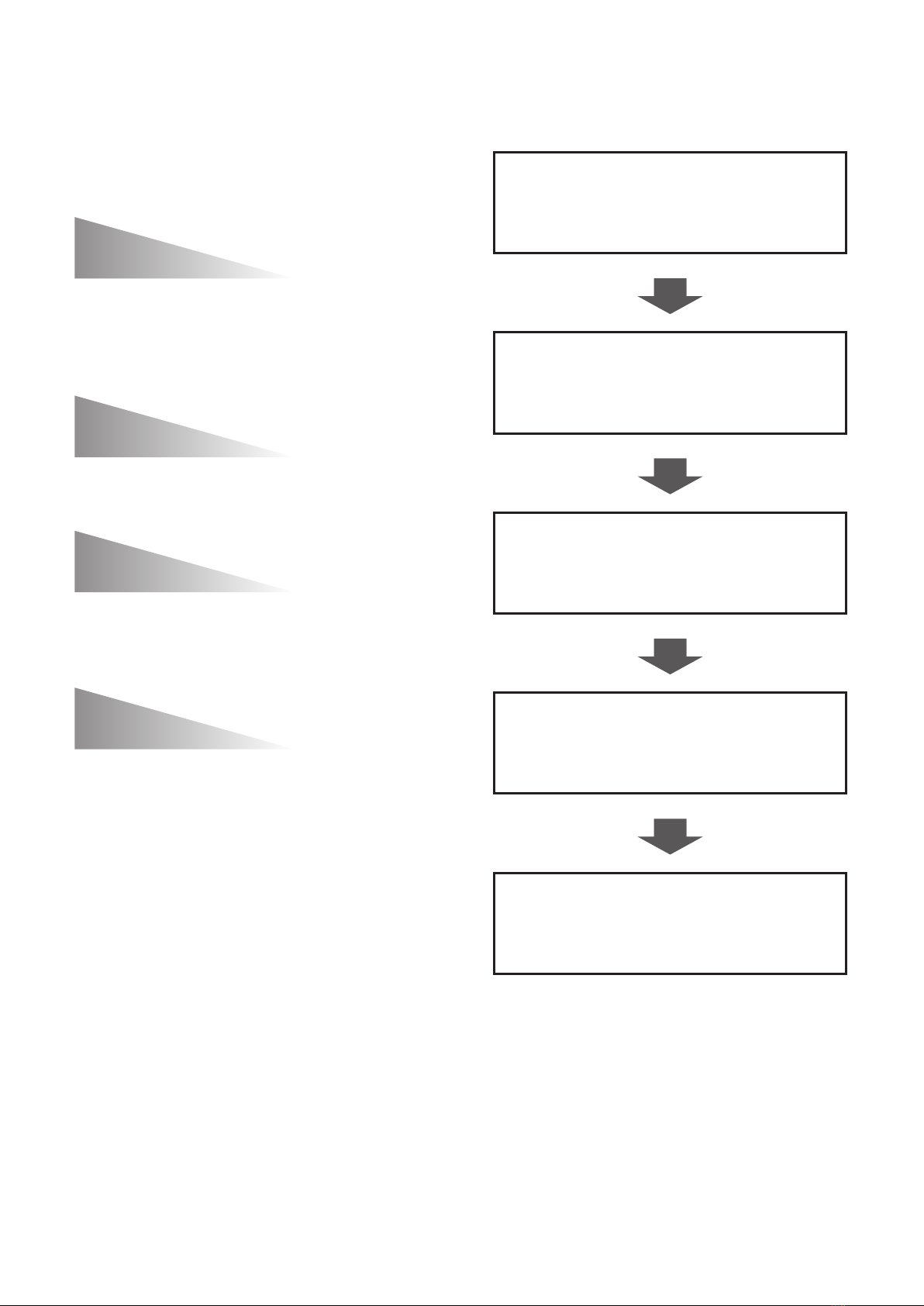
Quick steps
more…
Lens Memory
Memorize focus/zoom position of the lens,
for easy transition between different aspect
contents (ex. 16:9 to 2.35:1).
With auto switching capability.
Waveform Monitor
Adjust the luminance level of the input signal
to display full dynamic range of the content.
VIERA Link
Control multiple Panasonic devices and other
CEC compatible devices via HDMI cable using
the projector remote.
Set up your projector1.
See “Setting up” on page 14.
Connect with other devices2.
See “Connections” on page 15.
Prepare the remote control3.
See “Remote control” on
page 11.
Split Adjust Mode
Perform adjustments to the image by viewing
the before and after image side by side.
Consult the Functional Instructions included in
the CD-ROM for instructions on how to use these
features.
Start projecting4.
See “Switching the projector
on/off” on page 16.
Adjust the image5.
See “Menu Navigation” on
page 19.
Page 5

E
NGLISH - 5
Important
Information
PreparationSettingsMaintenanceAppendix
Getting
Started
Basic
Operation
Contents
Important Information
Important Safety Notice ................................ 2
Precautions with regard to safety ................ 6
WARNING .......................................................... 6
CAUTION ........................................................... 7
Cautions when transporting ..................................8
Cautions when installing..................................... 8
Cautions on use ................................................. 9
Cleaning and maintenance................................. 9
Disposal.............................................................. 9
Accessories ...................................................... 10
Preparation
About Your Projector ................................... 11
Remote control ..................................................11
Projector body .................................................. 12
Getting Started
Setting up ..................................................... 14
Screen size and throw distance ....................... 14
Projection method ............................................ 14
Lens shift and positioning ................................. 15
Connections ................................................. 15
Before connecting to the projector ................... 15
Settings
Menu Navigation .......................................... 19
Navigating through the MENU.......................... 19
Menu list ........................................................... 20
VIERA Link™ ................................................ 23
Using the Link functions (VIERA Link).............. 23
Maintenance
TEMP and LAMP Indicators ........................ 25
Managing the indicated problems .................... 25
Care and Replacement ................................ 26
Cleaning the projector ...................................... 26
Replacing the lamp unit .................................... 27
Troubleshooting ........................................... 29
Appendix
Technical Information .................................. 30
Ceiling mount bracket safeguards .................... 30
List of compatible signals ................................. 31
Specications ................................................... 32
Trademark acknowledgements ........................ 34
Dimensions....................................................... 34
Index ............................................................. 35
Basic Operation
Switching the projector on/off .................... 16
Power cord ....................................................... 16
Power indicator................................................. 16
Switching on the projector ................................ 17
Switching off the projector ................................ 17
Projecting an image ..................................... 18
Selecting the input signal ................................. 18
Positioning the image ....................................... 18
Page 6

6 - ENGLISH
Important
Information
Precautions with regard to safety
WARNING
POWER
The wall outlet or the circuit breaker shall
be installed near the equipment and shall
be easily accessible when problems occur.
If the following problems occur, cut off the
power supply immediately.
Continued use of the projector in these conditions will
result in re or electric shock.
If foreign objects or water get inside the projector,
z
cut off the power supply.
If the projector is dropped or the cabinet is broken,
z
cut off the power supply.
If you notice smoke, strange smells or noise coming
z
from the projector, cut off the power supply.
Please contact an Authorized Service Center for repairs,
and do not attempt to repair the projector yourself.
During a thunderstorm, do not touch the
projector or the cable.
Electric shocks can result.
Do not do anything that might damage the
power cord or the power plug.
If the power cord is used while damaged, electric
shocks, short-circuits or re will result.
Do not damage the power cord, make any
z
modications to it, place it near any hot objects,
bend it excessively, twist it, pull it, place heavy
objects on top of it or wrap it into a bundle.
Ask an Authorized Service Center to carry out any repairs
to the power cord that might be necessary.
Insert the power plug securely into the wall
outlet.
If the plug is not inserted correctly, electric shocks or
overheating will result.
Do not use anything other than the provided power
z
cord and ground in the wall outlet.
Do not use plugs which are damaged or wall outlets
z
which are coming loose from the wall.
Clean the power plug regularly to prevent it
from becoming covered in dust.
Failure to observe this will cause a re.
If dust builds up on the power plug, the resulting
z
humidity can damage the insulation.
If not using the projector for an extended period of
z
time, pull the power plug out from the wall outlet.
Pull the power plug out from the wall outlet and wipe it
with a dry cloth regularly.
Do not handle the power plug with wet hands.
Failure to observe this will result in electric shocks.
Do not overload the wall outlet.
If the power supply is overloaded (ex., by using too
many adapters), overheating may occur and re will
result.
ON USE/INSTALLATION
Do not place liquid containers on top of the
projector.
If water spills onto the projector or gets inside it, re or
electric shocks will result.
If any water gets inside the projector, contact an
Authorized Service Center.
Do not place the projector on soft materials
such as carpets or sponge mats.
Doing so will cause the projector to overheat, which can
cause burns, re or damage to the projector.
Do not set up the projector in humid or dusty
places or in places where the projector may
come into contact with oily smoke or steam,
ex., a bathroom.
Using the projector under such conditions will result
in re, electric shocks or components deterioration.
Components deterioration (such as ceiling mount
brackets) may cause the projector which is mounted on
the ceiling to fall down.
Do not install this projector in a place which
is not strong enough to take the full weight
of the projector or on top of a surface which
is sloped or unstable.
Failure to observe this will cause projector to fall down
or tip over the projector, and severe injury or damage
could result.
Do not place another projector or other
heavy objects on top of the projector.
Failure to observe this will cause the projector to
become unbalanced and fall, which could result in
damage or injury. The projector will be damaged or
deformed.
Installation work (
such as ceiling suspension
should only be carried out by a qualied
technician.
If installation is not carried out and secured correctly it
can cause injury or accidents, such as electric shocks.
Do not use anything other than an authorized
z
ceiling mount bracket.
Be sure to use the provided accessory wire as an
z
extra safety measure to prevent the projector from
falling down. (Install in a different location to the
ceiling mount bracket)
Do not cover the air inlet port or the air
outlet port.
Doing so will cause the projector to overheat, which can
cause re or damage to the projector.
Do not place the projector in narrow, badly
z
ventilated places such as closets or bookshelves.
Do not place the projector on cloth or papers, as
z
these materials could be drawn into the air inlet
port.
)
Page 7

Precautions with regard to safety
E
NGLISH - 7
Important
Information
Do not place your hands or other objects
close to the air outlet port.
Doing so will cause burns or damage your hands or
other objects.
Heated air comes out of the air outlet port. Do not
z
place your hands or face, or objects which cannot
withstand heat close to this port.
Do not look into or touch the lights emitted
from the lens while the projector is being used.
Doing so can cause burns or loss of sight.
Strong light is emitted from the projector’s lens. Do
z
not look or place your hands directly into this light.
Be especially careful not to let young children look
z
into the lens. In addition, turn off the power and
disconnect the power plug when you are away from
the projector.
Do not insert any foreign objects into the
projector.
Doing so will cause re or electric shocks.
Do not insert any metal objects or ammable objects
z
into the projector or drop them onto the projector.
Never attempt to remodel or disassemble
the projector.
High voltages can cause re or electric shocks.
For any inspection, adjustment and repair work, please
contact an Authorized Service Center.
Do not use the projector while the projection
lens cap is still attached to the projection lens.
If this is not observed, the lens cap will be damaged
and re will occur.
ACCESSORIES
Do not use or handle the batteries improperly,
and refer to the following.
Failure to observe this will cause burns, batteries to
leak, overheat, explode or catch re.
Do not use unspecied batteries.
z
Use manganese batteries or alkaline batteries.
z
Do not dissemble dry cell batteries.
z
Do not heat the batteries or place them into water
z
or re.
Do not allow the + and − terminals of the batteries
z
to come into contact with metallic objects such as
necklaces or hairpins.
Do not store batteries together with metallic objects.
z
Store the batteries in a plastic bag and keep them
z
away from metallic objects.
Make sure the polarities (+ and −) are correct when
z
inserting the batteries.
Do not use a new battery together with an old
z
battery or mix different types of batteries.
Do not use batteries with the outer cover peeling
z
away or removed.
Remove the empty batteries from the remote
z
control at once.
Insulate the battery using tape or something similar
z
before disposal.
Do not allow children to reach the batteries.
The battery can cause death by suffocation if
z
swallowed.
If swallowed, seek medical advice immediately.
z
If the battery uid leaks, do not touch it with
bare hands, and take the following measures
if necessary.
Battery uid on your skin or clothing could result in
z
skin inammation or injury.
Rinse with clean water and seek medical advice
immediately.
Battery uid coming in contact with your eyes could
z
result in loss of sight.
In this case, do not rub your eyes. Rinse with clean
water and seek medical advice immediately.
Do not disassemble the lamp unit.
If the lamp breaks, it could cause injury.
Lamp replacement
The lamp has high internal pressure. If improperly handled,
an explosion and severe injury or accidents will result.
Replacement of the lamp should be carried out by a
z
qualied technician.
The lamp can easily explode if struck against hard
z
objects or dropped.
Before replacing the lamp, be sure to disconnect
z
the power plug from the wall outlet.
Electric shocks or explosions can result if this is not
done.
When replacing the lamp, allow it to cool for at least
z
one hour before handling it otherwise it can cause
burns.
Do not allow infants or pets to touch the
remote control unit.
Keep the remote control unit out of the reach of
z
infants and pets after using it.
CAUTION
POWER
When disconnecting the power cord, hold
the plug, not the cord.
If the power cord itself is pulled, the cord will become
damaged, and re, short-circuits or serious electric
shocks will result.
When not using the projector for an
extended period of time, disconnect the
power plug from the wall outlet and remove
the batteries from the remote control.
Disconnect the power plug from the wall
outlet before carrying out any cleaning.
Electric shocks can result if this is not done.
Page 8

Precautions with regard to safety
8 - ENGLISH
Important
Information
ON USE/INSTALLATION
Do not put your weight on this projector.
You could fall or the projector could break, and injury
will result.
Be especially careful not to let young children stand
z
or sit on the projector.
Do not place the projector in extremely hot
locations.
Doing so will cause the outer casing or internal
components to deteriorate, or result in re.
Take particular care in locations exposed to direct
z
sunlight or near stoves.
Always disconnect all cables before moving
the projector.
Moving the projector with cables still attached can
damage the cables, which will cause re or electric
shocks to occur.
ACCESSORIES
Do not use the old lamp unit.
If used, it could cause lamp explosion.
If the lamp has broken, ventilate the room
immediately. Do not touch or bring your face
close to the broken pieces.
Failure to observe this will cause the user to absorb
the gas which was released when the lamp broke and
which contains nearly the same amount of mercury as
uorescent lamps, and the broken pieces will cause
injury.
If you believe that you have absorbed the gas or that the
gas has got into your eyes or mouth, seek medical advice
immediately.
Ask your dealer about replacing the lamp unit and check
the inside of the projector.
Do not place your hands in the openings
beside the optical lens, while shifting the lens.
Failure to observe this could cause injury.
Do not use projectors with the adjustable
feet or lens unit cover removed.
If this not observed, the sets will not operate correctly
or accidents will result.
Cautions when transporting
When transporting the projector or carrying it around,
make sure that the lens cap is always in place, and
remove the lens. Please take care to keep them away
from vibration and impacts, both the projector and
the lens are precision-made and easily susceptible to
damage.
When transporting the projector, the adjuster legs must
be housed and do not hold them. Please securely hold
only its bottom and none of its other parts or surfaces
as this will result in malfunctions.
Cautions when installing
Do not use under the following
conditions.
Do not set up the projector outdoors.
z
The projector is designed for indoor use only.
Avoid setting up in places which are subject to
z
vibration or shocks.
If the projector is installed in a place where
vibrations are transmitted or mounted in a car or a
vessel, vibrations or impacts will result in damage to
the internal parts, causing failure. Install the product
in a place free from vibrations and impacts.
Avoid setting up in places which are subject to
z
sudden temperature changes, such as near an
air conditioner or lighting equipment.
Failure to observe this will result in malfunctions or
the lamp life will be shortened.
See “TEMP indicator” on page 25.
Avoid setting up in places which are near high-
z
voltage power lines or near motors.
The product will be exposed to interference if it is
installed in the vicinity of high-voltage electrical
power lines or power sources.
Do not install the projector at elevations higher
z
than 2 700 m (8 858 ft) above sea level.
If using this projector at high elevations 1 400 2 700 m (4 593 - 8 858 ft) above sea level, set the
HIGH ALTITUDE MODE to ON.
Failure to observe this will result in malfunctions
or the lamp life or life of other components will be
shortened.
Be sure to ask a specialized
technician when installing the
product to a ceiling.
If the product is to be installed hanging from the ceiling,
purchase an optional hanging attachment (For high
ceilings: Model No. ET-PKE1000S, For low ceilings:
Model No. ET-PKE2000). Please call a specialized
technician or contact an Authorized Service Center for
installation.
Be sure to put on the lens unit cover
after installing the projection lens.
If this not done, dust will collect inside the projector and
problems with the projector can result.
Lens Focus
Do not adjust the lens focus in the initial period after
switching the projector on. The high clarity projector
lens is thermally affected by the light from the light
source, making the focus unstable in the period just
after switching on. Please allow a warm-up time before
adjusting the lens focus.
Page 9

Precautions with regard to safety
E
NGLISH - 9
Important
Information
Cautions on use
In order to get the picture quality
Draw curtains or blinds over windows and turn off any
lights near the screen to prevent outside light or light
from indoor lamps from shining onto the screen.
Depending on where the projector is used, air exhaust
vents or the warm air from air conditioning can cause a
shimmering effect on the screen. For this reason, take
care not to shield the air exhaust vents and consider
the direction of the air owing from air conditioning.
Do not adjust the lens focus in the initial period
z
(within approx. 30 minutes) after switching the
projector on.
Optical components
It may be necessary to replace the optical components
such as liquid crystal panels and polarizing plates
in less than 1 year if using the projector in a high
temperature environment or in a very dusty, oily smoke
or tobacco smoke environment. For more details,
please contact your dealer.
Liquid crystal panel
Do not project the same image for long periods of
time, as this may remain as an afterimage on the liquid
crystal panel. Display the white screen test pattern
for more than an hour to remove it. See the functional
instructions that is in the provided CD-ROM.
Do not touch the surface of the
projector lens with your bare hand.
If the surface of the lens becomes dirty from ngerprints
or anything else, this will be magnied and projected
onto the screen. Cover the lens with the lens cap when
the projector is not used.
The projector has a high pressure
mercury lamp that is characterized
as follows:
The brightness of the lamp will decrease over time.
z
The lamp may explode or shorten the lamp life by
z
shocks or chipping damage.
In rare cases, it may burst shortly after the rst use.
z
The possibility of its bursting increases when the
z
lamp is used beyond the replacement time.
If the lamp bursts, gas inside the lamp is released
z
in the form of smoke.
The life of a mercury lamp varies according to the
z
individual difference or conditions of use.
In particular, turning the power on and off frequently
z
and/or repeatedly as well as continuous use for
12 hours will greatly affect the life cycle. Provide a
lamp for replacement in advance.
Connection to external device
When connecting the projector to a computer or
external device, use the power cord supplied with the
corresponding device and a commercially available
shielded interface cable.
Cleaning and maintenance
Ask an Authorized Service Center
to clean the inside of the projector
at least once a year.
If dust is left to build up inside the projector without
being cleaned out, it can result in re or problems
with operation. It is a good idea to clean the inside of
the projector before the season when humid weather
arrives.
Ask your nearest Authorized Service Center to clean
the projector when required.
Please discuss with the Authorized Service Center
regarding cleaning costs.
Be sure to remove the power plug from the wall
z
outlet before cleaning.
Use soft and dry cloth to clean the cabinet.
z
Use a soft cloth moistened in warm water to clean
away oil. Do not use solvents such as benzene,
thinner, and alcohol, detergents for kitchens, or a
chemical cloth. If using such solvents, the outer case
will become deformed, and the paint may peel off.
Do not clean the lens surface with fuzzy or
z
dusty cloths.
If dust adheres to the lens, it will be magnied and
projected on the screen. Use a soft and clean cloth
to wipe off dust.
Disposal
When discarding this product, please contact your local
authorities or dealer and ask for the correct method of
disposal.
Page 10
Precautions with regard to safety
Power cord secure lock (x1)
Information
Important
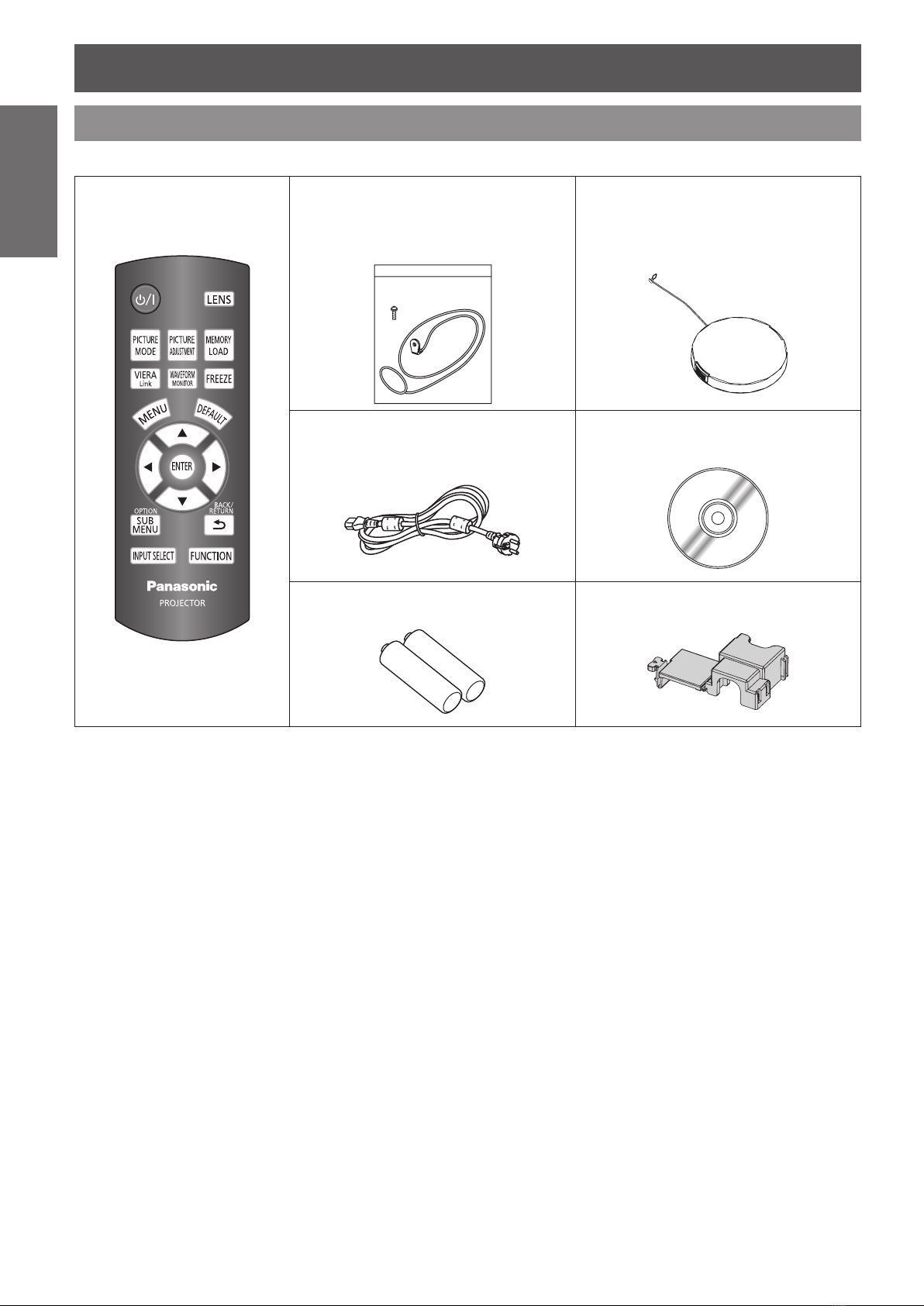
Accessories
Make sure the following accessories are provided with your projector.
Remote control for
N2QAYB000450
Safety cable
TTRA0141
Attachment screw (x1)
Safety cable (x1)
Power cord (x1)
K2CG3FH00019
3 m (9'10 1/8")
Lens cover (x1)
TXFKK01REGZ
(Attached to the projector by default.)
CD-ROM (x1)
TXFQB02REGZ
AA batteries for remote control (x2)
* The protectors for enclosed products, such as a plug
cover or foam cartons, must be treated properly.
TTRA0182
* Contact an Authorized Service Center for lost
accessories.
10 - ENGLISH
Page 11
Preparation
About Your Projector
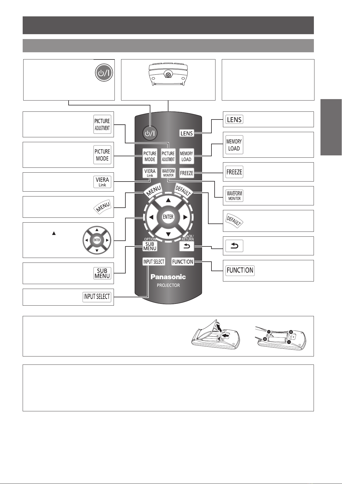
Remote control
Power button
While MAIN POWER is on,
switch between standby
mode and projection mode.
Display the PICTURE menu
or ADVANCED MENU.
Switch to cycle through the
PICTURE MODE.
Display the VIERA LINK
menu.
Display the main menu or
return to the previous menu.
Navigate through the
menus with
and activate the menu
item with the ENTER
button.
▼ ◄ ►,
Remote control signal emitter
Emit remote control signal.
Button backlight
When any button is pressed, the button
backlight is lit. Without any operation, it
gets darker after 5 seconds and goes
off after next 5 seconds.
Display the ZOOM/FOCUS
menu.
Display the MEMORY LOAD
menu.
Capture the projected image
as a still image.
Display the input waveform.
Reset some of the settings
to the factory default.
Return to the previous menu.
Preparation
Open the connected
equipment menu while using
the VIERA Link.
Switch to cycle through
the input method.
Battery compartment
Press the tab and lift up the cover.1.
Insert the batteries according to the polarity diagram indicated 2.
inside.
Note:
See the functional instructions that is in the provided CD-ROM for more details. •
Do not drop the remote control. •
Avoid contact with liquids or moisture. •
Use manganese batteries or alkaline batteries with the remote control. •
Do not attempt to modify or disassemble the remote control. Contact an Authorized Service Center for repairs. •
Do not keep pressing the remote control buttons as this may shorten battery life. •
Activate the assigned
function from the menu
options for shortcut.
NGLISH - 11
E
Page 12

About Your Projector
12 - ENGLISH
Preparation
Projector body
J
Top and front view
Air exhaust port
Heated air comes out
of this opening.
Projection lens
Lens cover
Protects the projection lens
from dust or dirt.
Lens shift dials • Vertical Lens shift dials • Horizontal
Remote control signal
receptor
Air exhaust port
Power/LAMP/TEMP
indicators
Air lter
MAIN POWER
Switch the projector on/off.
Navigate through the menus with ▲ ▼ ◄ ►,
and activate the menu item with the ENTER
button.
Power button
While MAIN POWER is on, switch between
standby mode and projection mode.
MENU
Display the main menu.
Return to the previous menu.
Note:
While the projector is not in use, keep the lens cover attached to protect the lens. •
CONTROL PANEL
(Push to open/close the cover.)
RETURN
Return to the previous menu.
INPUT SELECT
Switch to cycle through the
input method.
FOCUS and ZOOM
Adjust the focus and size of
the image.
Page 13

About Your Projector
E
NGLISH - 13
Preparation
J
Back and bottom view
Air intake port
Front leg adjusters
Screw up/down to adjust the
projection angle.
Security lock
Attach the commercial shackle lock
which is provided with the projector.
Compatible with the Kensington
MicroSaver Security System.
Lens cover attachment hole
Top cover
Hold the top cover at the back corner
and slightly push up to open.
Air intake port
AC IN
Connect the power cord to
supply electronic power to the
projector.
Safety cable attachment point
Attach the safety cable when
mounted on the ceiling.
Front leg adjusters
Screw up/down to adjust the
projection angle.
Connecting
terminals
NOTE:
The projector should only be used with the attached power cord to ensure optimum performance and avoid damage to •
the projector.
Do not open the top cover other than replacing the lamp unit. •
See the functional instructions that is in the provided CD-ROM for more details. •
COMPUTER IN
Connect an RGB/YPBPR signal
cable.
HDMI IN
Connect HDMI signal cables.
COMPONENT IN
Connect a YPBPR signal cable.
TRIGGER IN/OUT
Connect external equipment
controlling cables.
S-VIDEO IN
Connect an S-VIDEO
signal cable.
VIDEO IN
Connect an RCA
composite video cable.
SERIAL
Connect a compatible
cable for controlling the
projector remotely via
your computer.
Page 14

14 - ENGLISH
Getting
Started
SD
SW
SH
Getting Started
Setting up
Screen size and throw distance
You can adjust the projection size with 2 × zoom lens. Calculate and dene the throw distance as follows.
Projected image
All measurements and the calculation results below are approximate and may differ from the actual measurements.
Screen Diagonal
2.03 m (80") 2.4 m (7'10") 4.7 m (15'5") 2.6 m (8'6") 3.8 m (12'5")
2.54 m (100") 3.0 m (9'10") 5.9 m (19'4") 3.2 m (10'6") 4.7 m (15'5")
3.05 m (120") 3.6 m (11'9") 7.2 m (23'7") 3.8 m (12'5") 5.7 m (18'8")
When using both 2.35:1 and 16:9 aspect images onto a 2.35:1 sized screen.*1.
(SD)
Screen Screen
Throw distance (16:9) Throw distance (2.35:1)
Minimum distance
(LW)
Maximum distance
(LT)
Minimum distance
(LW)
*1
Maximum distance
(LT)
J
Calculation methods for screen dimensions
You can calculate more detailed screen dimensions from the screen diagonal.
16:9 size 2.35:1 size
Screen height (SH) = SD (m) × 0.490 = SD (m) × 0.392
Screen width (SW) = SD (m) × 0.872 = SD (m) × 0.920
Minimum distance (LW) = SD (m) × 1.189 − 0.04 = SD (m) × 1.256 − 0.04
Maximum distance (LT) = SD (m) × 2.378 − 0.05 = SD (m) × 1.899 − 0.05
NOTE:
You can tilt the projector body less than approximately ±30 ° vertically and ±10 ° horizontally. •
Overtilting may result in shortening the component’s life.
Do not cover the air exhaust/intake ports or place anything within 50 cm (19 5/8") of them. •
+30 °
−30 °
Projection method
You can use the projector with any of the following 4 projection methods. To set the projector in the desired
method, see “INSTALLATION” in “OPTION menu” of the functional instructions that is in the provided CD-ROM.
J
Mounting on the ceiling and
projecting from front
J
Setting on a desk/oor and
projecting from rear
J
Mounting on the ceiling and
projecting from rear
NOTE:
A translucent screen is required for rear projection. •
When mounting the projector on the ceiling, the optional ceiling mount bracket (ET-PKE2000, ET-PKE1000S) is required. •
See “Ceiling mount bracket safeguards” on page • 30.
INSTALLATION: FRONT/CEILING INSTALLATION: REAR/DESK
J
Setting on a desk/oor and
projecting from front
INSTALLATION: REAR/CEILING INSTALLATION: FRONT/DESK
Page 15

Setting up
E
NGLISH - 15
Getting
Started
Lens shift and positioning
If the projector is not positioned right in front of the center of the screen, you can adjust the projected image
position by moving the lens shift dials within the shift range of the lens.
J
Adjusting the lens shift dials
Horizontal shift Vertical shift
Q
Horizontal shift
You can place the projector where the projector
lens is up to 40 % horizontally off-center from the
screen and then adjust the image position with
the Lens shift dial • Horizontal.
Up to about 40 %
of the projection
Turning the dial
clockwise:
Image moves to the right
Up to about 40 %
of the projection
Turning the dial
counterclockwise:
Image moves to the left
Q
Vertical shift
You can place the projector where the projector
lens is up to 100 % vertically off-center from the
screen and then adjust the image position with
the Lens shift dial • Vertical.
Turning the dial counterclockwise:
Image moves to the bottom
Up to about 100 %
of the projection
Up to about 100 %
of the projection
Turning the dial clockwise:
Image moves to the top
Connections
Before connecting to the projector
Read and follow the operating and connecting instructions of each peripheral device.
The peripheral devices must be turned off.
Use cables that match each peripheral device to be connected.
Conrm the type of video signals. See “List of compatible signals” on page
Audio cables must be connected from each peripheral device directly to the audio reproduction system.
NOTE:
See the functional instructions that is in the provided CD-ROM. •
31.
Page 16

16 - ENGLISH
Basic
Operation
Basic Operation
Switching the projector on/off
Power cord
J
Connecting
Make sure the shape of the power plug and the 1.
AC IN terminal on the back of the projector match,
then push the plug all the way in.
Align the side of the 2. power cord secure lock with
the side guide rail of the AC IN terminal of the
projector and slide it in.
Place the latch to the latch catcher and press until 3.
it clicks.
J
NOTE:
Power indicator
Power indicator informs you of the status of the power.
Rail guide
Disconnecting
Unplug the power cord from the wall outlet.1.
Depress the latch and slide the cover off.2.
Do not use other than the provided power cord. •
Ensure all the input devices are connected and turned off before connecting the power cord. •
Do not force the connector as this may damage the projector and/or the power cord. •
Dirt or dust build-up around plugs may cause re or electrical hazards. •
Switch off the power to the projector when not in use. •
When the
indicator will turn red, and you cannot switch on the
power.
TEMP indicator is ashing, the power
Latch
Connect the power cord to a wall outlet.4.
Slide the power cord secure lock up along the side 3.
guide rail.
Hold the plug and unplug it from the 4. AC IN
terminal on the back of the projector.
Power indicator
Indicator status Status
No illumination or ashing MAIN POWER is switched off.
Lit MAIN POWER is switched on and the projector is in standby mode.
MAIN POWER is switched on (standby mode) and the POWER ON LINK is set to
Red
Flashing
Flashing The power button is switched on and the projector is getting ready to project.
Green
Lit Projecting.
Lit The power button is switched off and the projector is cooling the lamp.
Orange
Flashing
YES.
•
The power consumption is not much different when it is lit.
( See “VIERA Link Connection” of the functional instructions that is in the provided
CD-ROM.)
The power button is switched on again when cooling the lamp and recovering to
projection mode. Recovery may take a while.
NOTE:
See “TEMP indicator” on page • 25.
While the projector is cooling the lamp, do not switch • MAIN POWER off or unplug the power cord.
The electric consumption in standby mode is 0.08 W. •
Page 17

Switching the projector on/off
E
NGLISH - 17
Basic
Operation
Switching on the projector
(2)
(3)
(1)
(3)
(1)
(2)
Power indicator
Remove the lens cover from the lens.1.
Switch 2. MAIN POWER on.
The power indicator lights up in red.
Press the power button.3.
The power indicator lights up in green after ashing
for a while.
The
STARTUP LOGO is displayed on the screen.
See “STARTUP LOGO” in “OPTION menu” of
the functional instructions that is in the provided
CD-ROM.
NOTE:
When the internal cooling fan is operating, some operational sound may be heard. The loudness of the operational •
sound depends on the external temperature.
You can reduce the operational sound by setting the • LAMP POWER in OPTION menu to the ECO-MODE. See “LAMP
POWER” in “Option menu” of the functional instructions that is in the provided CD-ROM.
When starting up the projector, some small rattling or tinkling sound may be heard, or the display may icker for the •
characteristics of the lamp. Those are normal and will not affect the performance of the projector.
Do not attempt to modify the lens cover which may cause burns, re or damage to the projector. •
Switching off the projector
Power indicator
Press the power button.1.
NOTE:
Press the power button twice or for a long duration to switch the power off. •
The conrmation screen is displayed.
To return to the projection, press the
RETURN button.
MENU or
Press the power or 2. ENTER button.
The power indicator lights up in orange while cooling
the lamp, then illuminates red when it is ready to
switch off MAIN POWER.
Switch off 3. MAIN POWER on the left side of the
projector.
Attach the lens cover.4.
Page 18

Projecting an image
Selecting the input signal
Switch on the connected devices.1.
Press the play button of the required device.
Press the 2. INPUT SELECT button to select the
required input method if needed. See “Switching
the input signal” of the functional instructions that
is in the provided CD-ROM.
The image will be projected on the screen.
Positioning the image
NOTE:
AUTO SEARCH • is ON as default and the signal from
the connected devices is detected automatically.
See “AUTO SEARCH” in “OPTION menu” of the
functional instructions that is in the provided CD-ROM.
Operation
Basic
Adjust the projected image with the lens shift dials. 1.
See “Lens shift and positioning” on page 15.
Adjust the angle of the projector.2.
You can screw the front leg adjusters up/down to
control the angle of the projector for adjusting the
throwing angle.
Screw up the front leg adjusters, and an audible click
will be heard as the limit.
Adjust the focus and the projected image size.3.
Press +/− of the
adjust.
Press the
by the remote control. See “LENS CONTROL” of
the functional instructions that is in the provided CDROM.
FOCUS and ZOOM buttons to
LENS button to adjust the focus and zoom
NOTE:
Do not touch the air exhaust port as this may cause •
burns or injury.
If keystone distortion occurs, see “KEYSTONE” in •
“POSITION menu” of the functional instructions that is
in the provided CD-ROM.
If you adjust the focus, you may need to adjust the size •
of the image by pressing the ZOOM button again.
18 - ENGLISH
Page 19

Settings
-
+
-
+
-
+
-
+
-
+
-
+
PICTURE MODE
CONTRAST
BRIGHTNESS
COLOR
TINT
SHARPNESS
COLOR TEMPERATURE
DYNAMIC IRIS
WAVEFORM MONITOR
SPLIT ADJUST
ADVANCED MENU
MEMORY SAVE
MEMORY LOAD
MEMORY EDIT
NORMAL
ON
0
0
0
0
0
0
PICTURE
POSITION
LANGUAGE
LENS CONTROL
FUNCTION BUTTON
VIERA LINK
OPTION
ENTER
RETURN
SELECT
-
+
BRIGHTNESS
0
-
+
-
+
-
+
-
+
H-POSITION
V-POSITION
ASPECT
WSS
OVER SCAN
KEYSTONE
16:9
ON
0
0
+7
0
PICTURE
POSITION
LANGUAGE
LENS CONTROL
FUNCTION BUTTON
VIERA LINK
OPTION
ENTER
RETURN
SELECT
-
+
-
+
-
+
-
+
H-POSITION
V-POSITION
ASPECT
WSS
OVER SCAN
KEYSTONE
16:9
ON
0
0
+7
0
PICTURE
POSITION
LANGUAGE
LENS CONTROL
FUNCTION BUTTON
VIERA LINK
OPTION
ENTER
DEFAULT
RETURN
SELECT
-
+
BRIGHTNESS
0
Menu Navigation
Navigating through the MENU
J
Displaying the main menu
Press the MENU button to display the main
menu and the operating guidance.
Current
Main menu
Sub-menu
settings
Menu Navigation
J
Operating procedure
Press ▲ ▼ to scroll to the required main menu 1.
item and press the ENTER button to select.
The selected item is highlighted in orange and the
sub-menu is displayed on the right.
See “Menu list” on page
20.
J
J
J
Operating guidance
Contains the required buttons to adjust the settings.
Adjusting with the bar scale
items
The triangle mark under the bar indicates factory
default setting and the square indicates the current
.
setting
Current setting
Default
Returning to the previous menu
Press the MENU or RETURN button to return
to the previous menu. Press repeatedly to
escape from the menu mode and return to the
projection.
Resetting to the factory default
settings
You can reset most of the customized settings
to the factory defaults by pressing DEFAULT
button of the remote control.
Press ▲ ▼ to scroll to the required sub-menu item 2.
and press ◄ ► or the ENTER button to adjust.
The selected item is called up and the other menu
items disappear from the screen. The Called up item
will disappear after 5 seconds without any operation
and return to the menu mode.
If there is a lower level to the sub-menu item, the
next level will be displayed.
Press ◄ ► to adjust or set the selected item.3.
For items using a bar scale, the current settings are
displayed on the left of the bar scale.
You can cycle through the options of an item by
pressing ▲ ▼.
Press the 4. MENU or RETURN button to return to
the previous menu.
NGLISH - 19
E
Settings
Page 20

Menu Navigation
20 - ENGLISH
Settings
Menu list
The menu options are structured and categorized. You can navigate through the menu with ▲ ▼ ◄ ► buttons.
NOTE:
PICTURE MODE
NORMAL DYNAMIC
COLOR1 COLOR2
CINEMA1 CINEMA2
CINEMA3
CONTRAST
(Default: 0)
BRIGHTNESS
(Default: 0)
COLOR
(Default: 0)
TINT
(Default: 0)
(Default: 0)
(Default: 0)
ON OFF
WAVEFORM MONITOR
OFF
FULL SCAN(Y) FULL SCAN(R)
FULL SCAN(G) FULL SCAN(B)
SINGLE LINE SCAN(Y)
SINGLE LINE SCAN(R)
SINGLE LINE SCAN(G)
SINGLE LINE SCAN(B)
MONITOR POSITION
UPPER LEFT UPPER CENTER
UPPER RIGHT LOWER LEFT
LOWER CENTER LOWER RIGHT
AUTO ADJUST
START AUTO ADJUST
BLACK LEVEL ADJUST
WHITE LEVEL ADJUST
RGB ADJUST (BLACK)
RGB ADJUST (WHITE)
SPLIT ADJUST
AREA SELECT
SPLIT ADJUST MODE
NORMAL REVERSE
The underlined items are factory default settings. •
Some default settings vary by the selected input signal. •
Sub-menu items vary according to the selected input signal. •
Some settings are adjustable without any signals. •
PICTURE
It is possible to adjust the picture quality.
SHARPNESS
COLOR TEMPERATURE
DYNAMIC IRIS
▼
▲
ADVANCED MENU
GAMMA ADJUSTMENT
SIMPLE ADVANCED
NR
MPEG NR
FRAME CREATION
OFF MODE1
MODE2 MODE3
COLOR MANAGEMENT
PROFILE ADJUSTMENT MODE
START ADJUSTMENT LOG
PROFILE SAVE PROFILE DELETE
PROFILE NAME CHANGE
ON OFF
CINEMA REALITY
ON OFF
TV-SYSTEM
AUTO
NTSC NTSC 4.43
PAL PAL-M
PAL-N SECAM
RGB/YPbPr
AUTO RGB YPbPr
CONTRAST R
CONTRAST G
CONTRAST B
BRIGHTNESS R
BRIGHTNESS G
BRIGHTNESS B
x.v.Color
DETAIL CLARITY
(Default: 0)
(Default: 0)
(Default: 0)
(Default: 0)
(Default: 0)
(Default: 0)
(Default: 0)
(Default: 0)
(Default: 3)
MEMORY SAVE
MEMORY 1 - 16
MEMORY LOAD
MEMORY 1 - 16
MEMORY EDIT
MEMORY DELETE
MEMORY 1 - 16 ALL DELETE
MEMORY NAME CHANGE
MEMORY 1 - 16
SIGNAL MODE
Page 21

Menu Navigation
E
NGLISH - 21
Settings
POSITION
It is possible to adjust the image size and position.
H-POSITION
(Default: 0)
V-POSITION
(Default: 0)
DOT CLOCK
(Default: 0)
CLOCK PHASE
(Default: 0)
ASPECT
4:3 16:9 s16:9 14:9
ZOOM ZOOM1 ZOOM2 JUST
AUTO H-FIT V-FIT
WSS
ON OFF
OVER SCAN
KEYSTONE
(Default: 0)
AUTO SETUP
LANGUAGE
It is possible to change the display language.
▲
H-AREA POSITION
(Default: 0)
V-AREA POSITION
(Default: 0)
LEFT MASKING AREA
(Default: 0)
RIGHT MASKING AREA
(Default: 0)
UPPER MASKING AREA
(Default: 0)
LOWER MASKING AREA
(Default: 0)
FUNCTION BUTTON
It is possible to assign a useful function to the
FUNCTION
COLOR MANAGEMENT
GAMMA ADJUSTMENT
SPLIT ADJUST
WAVEFORM AUTO ADJUST
FRAME CREATION
NORMAL DYNAMIC
COLOR1 COLOR2
CINEMA1 CINEMA2
CINEMA3 TEST PATTERN
OPERATE OTHER DEVICE
ASPECT AUTO SETUP
CONTRAST BRIGHTNESS
BLANK HDMI 1 IN
HDMI 2 IN HDMI 3 IN
COMPUTER IN COMPONENT IN
S-VIDEO IN VIDEO IN
button.
LENS CONTROL
It is possible to adjust the lens position.
ZOOM/FOCUS
LENS MEMORY LOAD
LENS MEMORY 1 - 6
LENS MEMORY SAVE
LENS MEMORY 1 - 6
LENS MEMORY EDIT
LENS MEMORY DELETE
LENS MEMORY 1 - 6 ALL DELETE
LENS MEMORY NAME CHANGE
LENS MEMORY 1 - 6
AUTO SWITCHING
2.35:1 IMAGE DETECTION
OFF LENS MEMORY 1 - 6
16:9 IMAGE DETECTION
OFF LENS MEMORY 1 - 6
▼
VIERA LINK
It is possible to link with the connected equipment.
VIERA LINK CONTROL
RECORDER 1 - 3
PLAYER 1 - 3
HOME THEATER 1 - 3
CAMCORDER 1 - 3
LUMIX 1 - 3
OTHER 1 - 4
HOME THEATER VOLUME
HOME THEATER MUTE
OPERATE OTHER DEVICE
Page 22

Menu Navigation
22 - ENGLISH
Settings
INPUT GUIDE
DETAILED OFF
SIMPLE
OSD DESIGN
TYPE1 TYPE2
TYPE3
OSD POSITION
CENTER LOWER LEFT
LOWER CENTER LOWER RIGHT
UPPER LEFT UPPER CENTER
UPPER RIGHT
BACK COLOR
BLUE BLACK
STARTUP LOGO
ON OFF
AUTO SEARCH
ON OFF
HDMI SIGNAL LEVEL
NORMAL EXPAND
FRAME RESPONSE
NORMAL FAST
INSTALLATION
FRONT/DESK FRONT/CEILING
REAR/DESK REAR/CEILING
TRIGGER 1/2 SETTING
OFF
OUTPUT
POWER ON
SELECT LENS MEMORY 1 - 6
BLANK
SELECT 4:3 ASPECT
SELECT 16:9 ASPECT
SELECT S16:9 ASPECT
SELECT JUST ASPECT
SELECT ZOOM ASPECT
SELECT H-FIT ASPECT
SELECT V-FIT ASPECT
RS-232C COMMAND LINK
OPTION
It is possible to change the option settings.
▼
▲
DELAY TIME
0 SEC. 2 SEC. 4 SEC. 6 SEC.
8 SEC. 10 SEC. 20 SEC. 30 SEC.
INPUT
POWER ON/OFF BLANK
SLEEP
OFF 60 MIN. 90 MIN. 120 MIN.
150 MIN. 180 MIN. 210 MIN. 240 MIN.
HIGH ALTITUDE MODE
OFF ON
LAMP POWER
NORMAL ECO-MODE
VIERA LINK SETTINGS
VIERA LINK
ON OFF
POWER ON LINK
NO YES
POWER OFF LINK
YES NO
STAND-BY POWER SAVE
NO YES
AUTO POWER STAND-BY
NO YES (WITH REMINDER)
YES (NO REMINDER)
VERSION
TEST PATTERN
LAMP RUNTIME
NOTE:
See the functional instructions that is in the provided CD-ROM for more details. •
Page 23

E
NGLISH - 23
Settings
VIERA Link™
VIERA LINK CONTROL
RECORDER 1
VIERA LINK CONTROL
HOME THEATER VOLUME
HOME THEATER MUTE
OPERATE OTHER DEVICE
RECORDER 1
ENTER
RETURN
VIERA LINK
SELECT
VIERA LINK CONTROL
RECORDER 1
Using the Link functions (VIERA Link)
J
VIERA Link Control
You can control some functions of the connected equipment
with this projector remote control.
If you cannot operate, check the settings and the
equipment.
For details of the operations for the connected equipment,
please read the manual of the equipment.
Q
Access and operate the menu of the equipment
Press the 1. VIERA Link button and display the
VIERA LINK menu.
Press ▲ ▼ to select 2. VIERA LINK CONTROL.
Press ◄ ► to select the type of equipment you 3.
want to access from VIERA LINK CONTROL and
press the ENTER button.
( RECORDER/PLAYER/HOME THEATER/
CAMCORDER/LUMIX/OTHER)
“
HOME THEATER” means Player theater, Blu-ray
Disc theater or Recorder theater.
“
OTHER” means Tuner (set-top box), etc.
The menu of the accessed equipment
(Input mode will be changed automatically.)
If multiple recorders or players are connected
Operate the menu of the equipment4.
Projector remote control can be used.
( Controllable functions depend on the connected
equipment.)
If you access non-VIERA Link equipment
You can connect up to three recorders or players at
the same time.
Recorder 1 - 3/Player 1 - 3
Some type of equipment is indicated by a number
following the device name in the order of ascending
The type of the connected equipment is displayed.
You can access the menu of the equipment. But you
cannot operate it. Please use its own remote control
to operate the equipment.
HDMI terminal connection. For example, if two
recorders are connected to HDMI2 and HDMI3, in this
case the recorder connected to HDMI2 is displayed as
“Recorder 1”, and the recorder connected to HDMI3 is
displayed as “Recorder 2”.
NOTE:
Some operations may not be available depending on the equipment. In this case use its own remote control to operate •
the equipment.
(For example)
The colored buttons operations, such as changing the date of TV program list for Blu-ray Disc Recorder cannot be
controlled by the projector remote control.
Page 24

VIERA Link™
VIERA LINK CONTROL
HOME THEATER VOLUME
HOME THEATER MUTE
OPERATE OTHER DEVICE
RECORDER 1
VIERA LINK
VIERA LINK CONTROL
HOME THEATER VOLUME
HOME THEATER MUTE
OPERATE OTHER DEVICE
RECORDER 1
VIERA LINK
J
Speaker control
You can control the theater speaker with this projector remote control.
If you cannot operate, check the settings and the equipment.
Q
Access and operate the speaker volume
Select 1. HOME THEATER VOLUME in the VIERA
LINK menu and press the ENTER button.
Volume side bar will be displayed.
Press ◄ ► to adjust the volume of the equipment.2.
Q
MUTE setting
Select 1. HOME THEATER MUTE in VIERA LINK
menu and press the ENTER button.
You can switch to turn off/on the sound by pressing the
ENTER button.
NOTE:
These functions may not work properly depending on the connected equipment. •
Image or sound may not be available for the rst few seconds when input mode is switched. •
HDAVI Control 4 • is the newest standard (current as of August, 2009) for HDAVI Control compatible equipment. This
standard is compatible with conventional HDAVI equipment.
HOME THEATER • (Player theater, Blu-ray Disc theater or Amplier) will be automatically turned on if it is in standby
mode, and the sound from the theater speakers connected to the equipment is turned on.
J
Q
Settings
NOTE:
Other manufacturer’s equipment control
You can control other manufacturer’s connected equipment by the projector remote control.
Access and operate the menu of the other manufacturer’s equipment
Press the 1. VIERA Link button on the remote control.
The
VIERA LINK menu will be displayed.
Press ◄ ► to select your required equipment from 2.
the VIERA LINK CONTROL menu.
Press the 3. ENTER button.
Your selected equipment will be switched to the HDMI
input which is connected to the projector.
Select 4. OPERATE OTHER DEVICE and press the
ENTER button.
Remote control image will appear on the screen, so 5.
please follow it to operate.
See “VIERA Link Connection” of the functional instructions that is in the provided CD-ROM. •
24 - ENGLISH
Page 25

Maintenance
TEMP and LAMP Indicators
Managing the indicated problems
If a problem should occur with the projector, the LAMP and/or TEMP
indicators will inform you. Manage the indicated problems as follows.
Conrm the status of all indicators and projector, and switch off 1.
the projector in proper way.
Find out the cause of the problem by status of the 2. LAMP and/
or TEMP indicators.
Follow the following instruction for each indication and solve 3.
the problem.
Turn on the projector in the correct way and conrm the 4.
indicator is not indicating a problem any longer.
J
TEMP indicator
Illuminating red while projecting and the alert will be displayed.
Indicator
Problem
Cause
Remedy
Flashing red and the power button is turned off automatically.
When the
Adjustments can be performed but not all changes will be shown on the image.
The temperature inside and/or outside the projector is abnormally high.
The air intake and exhaust
ports are covered.
Remove the object(s)
from the ventilation
openings or clear around
the projector.
TEMP indicator is lit, the lamp might have darkened.
The room temperature is
too high.
Reinstall the projector in
a temperature controlled
place. See page 32.
Power LAMP TEMP
The air lter is excessively
dirty and the ventilation is
poor.
Clean or replace the air
lter in the proper method.
See page 26.
The projector is located
at high elevations (above
1 400 - 2 700 m).
Turn on the projector and
set the HIGH ALTITUDE
MODE to ON.
See “INSTALLATION” of
the functional instructions
that is in the provided CDROM.
J
LAMP indicator
Indicator
Problem
Cause
Remedy
Illuminating red Flashing red
LAMP RUNTIME has
reached 1 800 hours.
The lamp unit will run out
soon and needs to be
replaced.
See “Replacing the lamp
unit” on page 27.
NOTE:
If no problem is found or the problem remains, do not turn on the projector. Instead contact an Authorized Service Center. •
Lamp circuit failure, abnormal function or lamp unit is damaged.
The power is turned on
again before the lamp unit
is cooled enough.
Let the lamp unit cool
down and turn on the
power after 90 seconds.
Lamp circuit failure,
abnormal function.
Contact an Authorized
Service Center.
The lamp unit is damaged.
See “Replacing the lamp
unit” on page 27.
Maintenance
NGLISH - 25
E
Page 26

26 - ENGLISH
Maintenance
Care and Replacement
Cleaning the projector
J
Before cleaning the projector
Switch off
Unplug all the cables from the projector.
J
Cleaning the outer surface of the projector
Wipe off dirt and dust gently with a soft cloth.
If it is difcult to remove the dirt, soak a cloth in water, wring the cloth well and then wipe the projector. Dry off the
projector with dry cloth.
Do not use petroleum benzine, thinner, any alcoholic solvent, kitchen detergents or chemical clothes. Failure to
observe these may result in altered or damaged surface of the projector.
J
Cleaning the lens surface
Wipe off dirt and dust gently with a lint-free cloth.
Make sure no dirt or dust remains on the surface of the lens. It will be enlarged and projected onto the screen.
J
Cleaning the air lter
If the air lter is excessively dirty, the internal temperature of the projector increases and may cause
malfunction. Clean the air lter regularly every 100 hours of usage.
Place a nger at the bottom of the air lter.1.
Slightly push up and pull out the air lter to remove.2.
MAIN POWER in proper way and disconnect the power plug from the wall outlet.
Vacuum dirt and dust from the air lter.3.
Place and slightly slide in the air lter in the air intake port to attach.4.
NOTE:
Do not use the projector without attaching the air lter. •
J
Replacing the air lter
The air lter should be replaced when cleaning is ineffective and when replacing the lamp unit. A replacement
air lter (TXFKN01VKF5) is provided with a replacement lamp unit, ET-LAE4000. Contact an Authorized
Service Center for the optional air lter.
Do not wash the air lter.
Make sure the air lter clicks into the place.
Page 27

Care and Replacement
E
NGLISH - 27
Maintenance
REPLACE LAMP
Replacing the lamp unit
J
Before replacing the lamp unit
Switch off
Wait for more than 1 hour and make sure the lamp unit and the surroundings are cooled enough.
Unplug all the cables from the projector.
Prepare a Phillips-head screwdriver.
Contact an Authorized Service Center to purchase a replacement lamp unit (ET-LAE4000).
When the projector is mounted on the ceiling, do not work directly under the projector or put your face closer to the
projector.
NOTE:
Prior to replacing the lamp unit, allow it to cool down to prevent the risk of burns, damage and other hazards. •
Do not attempt replacement with an unauthorized lamp unit. •
J
When to replace the lamp unit
The lamp unit is consumable and the brightness decreases by duration of usage. The LAMP indicator will
inform you of the replacement timing at 1 800 hours, and at 2 000 hours, the projector will be turned off.
Those gures are rough guidance and might be shortened by the usage conditions, characteristics of the
lamp unit, environmental conditions, and so on. You can check the duration of usage time using LAMP
RUNTIME in the OPTION menu.
MAIN POWER in proper way and disconnect the power plug from the wall outlet.
On screen LAMP indicator
Indication
“REPLACE LAMP” is displayed on the upper left
Over 1 800 hours
Over 2 000 hours
of the screen for 30 seconds.
To clear the screen immediately, press any
button.
“REPLACE LAMP” is displayed on the upper left
of the screen, and it will stay until you respond.
To clear the screen, press any button.
Illuminates red.
NOTE:
The guide times, 1 800 and 2 000 hours, are rough estimates based on certain conditions and are not guaranteed time. •
The estimated condition is: LAMP POWER in OPTION menu set to NORMAL.
To prolong the lamp life, set the • LAMP POWER in OPTION menu to ECO-MODE. See “LAMP POWER” in “OPTION
menu” of the functional instructions that is in the provided CD-ROM.
For more information about the lamp unit, such as guaranteed time, see the instructions which is provided with the lamp •
unit.
J
Opening the top cover
Hold at the back corner of the top cover and 1.
slightly push up to open.
Unhook the top cover safety hook from the 2.
projector.
Hold the top cover up and press both sides of 3.
hinge parts to remove.
When the projector is mounted on the ceiling,
removing the hinge parts is not required.
Remove the top cover aside.4.
Top cover safety hook
NOTE: When the projector is mounted on
the ceiling:
Place yourself at the back side of the projector, then •
open and close the top cover.
Do not work directly under the projector or put your •
face close to the projector.
Press here
Hinge parts
Page 28

Care and Replacement
28 - ENGLISH
Maintenance
HIGH ALTITUDE MODE
LAMP POWER
VIERA LINK SETTINGS
TEST PATTERN
LAMP RUNTIME
OFF
NORMAL
1820H
J
Removing and replacing the lamp unit
Use a Phillips screwdriver to loosen the 3 lamp 1.
unit xing screws until the screws turn freely.
Lamp unit
xing screws
Lamp unit lock
Hold the handle of the lamp unit and release the 2.
lamp unit lock in the direction of an arrow.
Pull out the lamp unit gently from the projector.3.
J
Attaching the top cover
Attach the hinge parts of the top cover to the 1.
projector and press slightly until it clicks.
When the projector is mounted on the ceiling,
attaching the hinge parts is not required.
Hook the top cover safety hook to the projector.2.
Hook the tabs of the top cover to the front of the 3.
projector body and lower slowly.
Press the back corner of the top cover gently until 4.
it clicks.
Make sure to hook the top cover safety hook to the
body.
Replace the new lamp unit while making sure that 4.
the direction of insertion is correct.
Press the top of the lamp unit downwards and make
sure the unit is installed securely.
Press down herePress down here
Tighten the lamp unit xing screws securely with a 5.
Phillips screwdriver.
Top cover safety hook Tabs
NOTE:
Be sure to install the lamp unit and the top cover of the projector securely. If they are not •
securely installed, it may cause the protection circuit to operate so that the power cannot be
turned on.
Grip the handle and keep the lamp unit paralleled when you remove the lamp unit. •
Do not switch the power on while the top cover is opened. •
When the projector is mounted on the ceiling, keep the lamp unit paralleled up and remove. •
J
Resetting the
If the lamp usage time has passed 2 000 hours (when LAMP POWER has been set to NORMAL), the
projector will switch to standby mode after approximately 10 minutes of operation. The resetting procedure
should thus be completed within 10 minutes.
Connect the power cord to the projector and a wall 1.
outlet, and switch MAIN POWER on.
Switch the power button.2.
Press the 3. MENU button to display the menu.
Press ▲ ▼ to select 4. OPTION and press the
ENTER button.
Press ▲ ▼ to select 5. LAMP RUNTIME.
LAMP RUNTIME
Press and hold the 6. ENTER button for
approximately 3 seconds.
The conrmation screen will be displayed and 7.
select OK.
Switch off the power button to reset the duration of 8.
the LAMP RUNTIME.
Conrm the duration of time in 9. LAMP RUNTIME is
reset to “0”.
Page 29

E
NGLISH - 29
Maintenance
Troubleshooting
Should any problem persist, contact your dealer.
Problem Cause
Power does not turn on.
No picture appears.
The picture is fuzzy.
The color is pale or grayish.
The Remote control does
not operate.
The picture does not
display correctly.
Picture from a computer
does not appear.
The power cord may not be connected.
MAIN POWER
No electric supply is at the wall outlet.
TEMP
indicator is lit or ashes. 25
LAMP
indicator is lit or ashes. 25
The lamp unit has not been securely installed.
The circuit breakers have tripped.
The signal input source may not be connected to a terminal properly.
The input selection setting may not be correct.
The
BRIGHTNESS adjustment setting may be at the minimum
setting.
The
BLANK function may be in use. CD-ROM
The lens cover may still be attached to the lens.
The lens focus may not have been set correctly.
The projector may not be at the correct distance from the screen.
The lens may be dirty.
The projector may be tilted too much.
COLOR
The equipment which is connected to the projector may not be
adjusted correctly.
The batteries may be weak.
The batteries may not have been inserted correctly.
The remote control signal receptor on the projector may be
obstructed.
The remote control unit may be out of the operation range.
The signal format may not have been set correctly.
There may be a problem with the VCR or other signal source.
A signal which is not compatible with the projector is being input.
The cable may be longer than the optional cable.
The external video output from a personal computer may not be
correct. (You may be able to change the external output settings
by pressing the [Fn] + [F3] or [Fn] + [F10] keys simultaneously. The
actual method varies depending on the type of computer; refer to the
documentation provided with your computer for further details.)
is turned off. 17
or TINT adjustment may be incorrect. CD-ROM
Reference
page
16
16
27
-
15
18
CD-ROM
12
18
14
26
15
-
-
11
CD-ROM
CD-ROM
CD-ROM
-
31
-
-
Page 30

30 - ENGLISH
Appendix
Appendix
Technical Information
Ceiling mount bracket safeguards
The projector and the ceiling mount bracket are designed for sufcient safety. However, make sure the safety cable
provided with the projector is installed and attached to the bottom of the projector when mounting on the ceiling for
safety and security.
Make sure to use a torque driver and do not use an electrical screwdriver or an impact screwdriver.
M4×0.7
9 mm
Torque: 1.25 ± 0.2 N·m
NOTE:
Even if it is during guaranteed period, the manufacturer is not responsible for any hazard or damage caused by using a •
ceiling mount bracket which is not purchased from an authorized distributors, or environmental conditions.
Installation work of the ceiling mount bracket should only be carried by a qualied technician. •
Remove an unused ceiling mount bracket promptly. •
J
Installing the safety cable
Install the ceiling mount bracket according to the Installation Instructions.1.
Loop the safety cable around the ceiling mount bracket with less slack.2.
Lace the cable of the end with a latch through the loop on the other end of the cable.
Loop once
* Indicated above is ET-PKE1000S. * Indicated above is ET-PKE2000.
Attach the latch on to the bottom of the projector with a provided screw.3.
Loop twice
M4×0.7
9 mm
Torque: 1.25 ± 0.2 N·m
Page 31

Technical Information
E
NGLISH - 31
Appendix
List of compatible signals
Display
Mode Display
NTSC/NTSC 4.43/
PAL-M/PAL60
PAL/PAL-N/SECAM - 720 × 576i 15.6 50.0 - A
525i (480i) 480i 720 × 480i 15.7 59.9 13.5 A
625i (576i) 576i 720 × 576i 15.6 50.0 13.5 A
525p (480p) 480p 720 × 483 31.5 59.9 27.0 A
625p (576p) 576p 720 × 576 31.3 50.0 27.0 A
1 125 (1 080)/60i 1 080/60i 1 920 × 1 080i 33.8 60.0 74.3 AA
1 125 (1 080)/50i 1 080/50i 1 920 × 1 080i 28.1 50.0 74.3 AA
1 125 (1 080)/24p 1 080/24p 1 920 × 1 080 27.0 24.0 74.3 AA
1 125 (1 080)/60p 1 080/60p 1 920 × 1 080 67.5 60.0 148.5 AA
1 125 (1 080)/50p 1 080/50p 1 920 × 1 080 56.3 50.0 148.5 AA
750 (720)/60p 720/60p 1 280 × 720 45.0 60.0 74.3 AA
750 (720)/50p 720/50p 1 280 × 720 37.5 50.0 74.3 AA
VGA480 VGA60 640 × 480 31.5 59.9 25.2 A
SVGA SVGA55 800 × 600 35.2 56.3 36.0 A
WIDE720 WIDE720 1 280 × 720 45.1 60.1 76.5 AA
XGA XGA60 1 024 × 768 48.4 60.0 65.0 A
WIDE768 WIDE768 1 280 × 768 45.3 56.5 76.2 A
MXGA MXGA70 1 152 × 864 64.0 71.2 94.2 A
SXGA SXGA60 1 280 × 1 024 64.0 60.0 108.0 A
SXGA60+ SXGA60+ 1 400 × 1 050 65.1 59.9 122.4 A
WIDE768-2 WIDE768-2 1 360 × 768 48.8 59.8 74.3 A
WIDE800 WIDE800 1 280 × 800 49.7 59.8 83.5 A
WIDE900 WIDE900 1 440 × 900 55.9 59.8 106.5 A
WIDE1080/60 WIDE1080/60 1 920 × 1 080 66.5 59.9 138.5 AA
WIDE1080/50 WIDE1080/50 1 920 × 1 080 55.6 49.9 141.5 AA
- 720 × 480i 15.7 59.9 - A
VGA75 640 × 480 37.5 75.0 31.5 A
VGA85 640 × 480 43.3 85.0 36.0 A
VGA138 640 × 480 72.1 138.0 62.3 A
SVGA60 800 × 600 37.9 60.3 40.0 A
SVGA70 800 × 600 48.1 72.2 50.0 A
SVGA75 800 × 600 46.9 75.0 49.5 A
SVGA85 800 × 600 53.7 85.1 56.3 A
XGA70 1 024 × 768 56.5 70.1 75.0 A
XGA75 1 024 × 768 60.0 75.0 78.8 A
XGA85 1 024 × 768 68.7 85.0 94.5 A
XGA89 1 024 × 768 72.1 89.0 99.2 A
MXGA75 1 152 × 864 67.5 74.9 108.0 A
resolution
*1
(dots)
Scanning
frequency
H
(kHz)V (Hz)
Dot clock
frequency
(MHz)
Picture
quality
The “i” appearing after the resolution indicates an interlaced signal.*1.
The following symbols are used to indicate picture quality.*2.
AA Maximum picture quality can be obtained.
A Signals are converted by the image processing circuit before picture is projected.
*2
Format
VIDEO/S-VIDEO
BPR
RGB
BPR
/HDMI
RGB/YP
RGB/YP
Page 32

Technical Information
Specications
Power supply AC 100 - 240 V 50 Hz/60 Hz
Power consumption
Amps 3.0 A - 1.5 A
Panel size (diagonal) 0.74 type (17.78 mm)
Aspect ratio 16:9
LCD panel
Lens
Lamp UHM lamp (170 W)
Luminosity
Operating environment
Display method 3 transparent LCD panels (RGB)
Drive method Active matrix method
Pixels 2 073 600 (1 920 × 1 080) × 3 panels
*1
Less than 240 W
During standby (when fan is stopped): 0.08 W (at 220 V)
Motorized zoom (2 ×)/Motorized focus
F 1.9 - 3.2, f 22.4 mm - 44.8 mm
1 600 lm
Temperature
Humidity 20 % - 80 % (no condensation)
0 °C - 40 °C (32 °F - 104 °F)
When the HIGH ALTITUDE MODE
(See the functional instructions
that is in the provided CD-ROM.)
is set to ON: 0 °C - 35 °C
(32 °F - 95 °F)
Scanning
frequency
(for RGB signal)
COMPONENT (YP
Color system 7 (NTSC/NTSC 4.43/PAL/PAL-M/PAL-N/PAL60/SECAM)
Projection size 40" - 300" (1 016 mm - 7 620 mm)
Throw distance 1.2 m - 18 m (3'11" - 59')
Installation
Appendix
Horizontal scanning
frequency
*2
Measurement, measuring conditions and method of notation all comply with ISO 21118 international *1.
standards.
See “List of compatible signals” on page *2. 31 for available signals.
Vertical scanning
frequency
Dot clock frequency Less than 150 MHz
BPR
) signals
30 kHz - 70 kHz
50 Hz - 87 Hz
525i (480i), 525p (480p), 625i (576i), 625p (576p), 750 (720)/60p,
750 (720)/50p, 1 125 (1 080)/60i, 1 125 (1 080)/50i, 1 125 (1 080)/60p,
1 125 (1 080)/50p, 1 125 (1 080)/24p
FRONT/DESK, FRONT/CEILING, REAR/DESK, REAR/CEILING
(Menu selection method)
32 - ENGLISH
Page 33

Terminals
Technical Information
S-VIDEO IN Single-line, Mini DIN 4p Y: 1.0 V [p-p], C: 0.286 V [p-p], 75 Ω
VIDEO IN Single-line, RCA pin jack 1.0 V [p-p], 75 Ω
Single-line, D-sub HD 15-pin (female)
R.G.B. 0.7 V [p-p], 75 Ω
G.SYNC 1.0 V [p-p], 75 Ω
COMPUTER IN
COMPONENT IN
HDMI IN
SERIAL D-sub 9-pin RS-232C compatible
HD/SYNC TTL high impedance, automatic
positive/negative polarity
compatible
VD TTL high impedance, automatic
positive/negative polarity
compatible
B/CB
Y, P
Y: 1.0 V [p-p] (including sync), 75 Ω
B/CB
, PR/C
P
Triple-line, 19-pin HDMI connector
HDMI™ (Deep Color, x.v.Color™), HDCP/HDAVI Control Ver. 4
compliant
, PR/C
R
R
Single-line, RCA pin jack × 3
0.7 V [p-p], 75 Ω
TRIGGER
Cabinet Moulded plastic (PC+ABS)
Dimensions
Weight Approx. 7.3 kg (16.09 lbs.)
Certications
Power supply 3 V DC (AA battery × 2)
Operating range Approx. 7 m (22'11")
Weight 125 g (4.4 ozs.) (including batteries)
Remote control
Dimensions
Cable cover ET-PCE2000
Options
Ceiling bracket ET-PKE2000/ET-PKE1000S
Dual-line monaural mini jack DC 12 V, max.100 mA
(Selectable for input and output by menu operation.)
Width 460 mm (18 1/8")
Height 130 mm (5 1/8")
Length 300 mm (11 3/4")
(excluding protruding parts)
UL60950-1 C-UL
FCC Class B ICES-003
(when operated directly in front of signal receptor)
Width 48 mm (1 7/8")
Length 138 mm (5 3/8")
Height 28.35 mm (1 1/8") (excluding
*1
protruding parts)
Average value. Each product has an individual variability in weight.*1.
Appendix
NGLISH - 33
E
Page 34

Technical Information
34 - ENGLISH
Appendix
300 (11 3/4")
460 (18 1/8")
230 (9")
15 (5/8")
147 (5 3/4")
60 (2 3/8")
116
(4 5/8")
130
(5 1/8")
17 (5/8")
Trademark acknowledgements
HDAVI Control™ and VIERA Link™ are trademarks.
VGA and XGA are trademarks of International Business Machines Corporation.
S-VGA is a registered trademark of the Video Electronics Standards Association.
HDMI, the HDMI logo and High-Denition Multimedia Interface are trademarks or registered trademarks of
HDMI Licensing LLC.
The font used in the on-screen displays is a Ricoh bitmap font, which is manufactured and sold by Ricoh
Company, Ltd.
All other trademarks are the property of the various trademark owners.
Dimensions
Unit: mm
Page 35

E
NGLISH - 35
Appendix
Index
A
Accessories ..................................10
AC IN ...........................................13
Air exhaust port ............................ 12
Air lter ......................................... 12
Replacing ..............................26
Air intake port ............................... 13
B
Batteries
Accessory ..............................10
Compartment ........................ 11
C
CD-ROM
Accessories ........................... 10
Menu .....................................19
Ceiling mount bracket ..................30
Cleaning ....................................... 26
COMPONENT IN
Terminal ................................. 13
COMPUTER IN
Terminal ................................. 13
Connections ................................. 15
CONTROL PANEL ....................... 12
D
DEFAULT
Remote control button ........... 11
Remote control function ........19
Dimensions ..................................34
E
ENTER
Control panel button .............. 12
Remote control button ........... 11
F
FOCUS
Control panel button .............. 12
FREEZE
Remote control button ........... 11
Front leg adjusters .......................13
FUNCTION
Remote control button ........... 11
FUNCTION BUTTON
Remote control buttons ......... 11
H
HDMI IN
Terminal ................................. 13
HOME THEATER MUTE ..............24
HOME THEATER VOLUME .........24
L
LAMP
Indicator status ...................... 25
LAMP Indicator ......................12
LAMP RUNTIME .......................... 28
Lamp unit
Replacing ..............................27
LENS
Remote control button ........... 11
LENS CONTROL
Remote control button ........... 11
Lens cover ...................................12
Accessory ..............................10
Attachment hole ....................13
Lens shift
Lens shift dial • Horizontal ..... 12
Lens shift dial • Vertical ......... 12
M
MAIN POWER .............................12
MEMORY LOAD
Remote control button ........... 11
Menu
Menu list ................................ 20
Navigation .............................19
MENU
Control panel button .............. 12
Remote control button ........... 11
Remote control function ........19
N
Navigation buttons
Control panel button .............. 12
Remote control button ........... 11
O
OPERATE OTHER DEVICE ........24
P
PICTURE ADJUSTMENT
Remote control button ........... 11
PICTURE MODE
Remote control button ........... 11
Power
Control panel button .............. 12
Indicator ................................12
Indicator status ...................... 16
Remote control button ........... 11
Power cord ................................... 12
Accessory ..............................10
Connecting ............................ 16
Power cord secure lock ..........10, 16
Projection lens .............................12
R
Remote control ............................. 11
Accessory ..............................10
Signal emitter ........................ 11
Signal receptor ...................... 12
RETURN
Control panel button .............. 12
Remote control button ........... 11
Remote control function ........19
S
Safety cable .................................30
Accessory ..............................10
Attachment point ...................13
Screen size ..................................14
Calculation methods ..............14
Security lock .................................13
SERIAL
Terminal ................................. 13
Specications ............................... 32
S-VIDEO IN
Terminal ................................. 13
T
Technical Information ................... 30
TEMP
Indicator ................................12
Indicator status ...................... 25
Throw distance .............................14
Top cover ...............................13, 27
TRIGGER
Terminal ................................. 13
Troubleshooting ...........................29
V
VIDEO IN
Terminal ................................. 13
VIERA Link ...................................23
Remote control button ........... 11
VIERA LINK CONTROL ............... 23
W
WAVEFORM MONITOR
Remote control button ........... 11
Z
ZOOM
Control panel button .............. 12
I
INPUT SELECT
Control panel button .............. 12
Remote control button ........... 11
INSTALLATION
Projection method .................14
Page 36

P1009-1109B
TQBJ0309
 Loading...