

Panasonic PM Series INSTRUCTION MANUAL
INSTRUCTION MANUAL
Photoelectric Sensor
Built-in U-shaped Micro-photosensor
PM-غ24(P)ޔPM-غ24-RޔPM-غ44(P)ޔPM-غ54(P)
Thank you very much for using SUNX products. Please
read this Instruction Manual carefully and thoroughly for
the correct and optimum use of this product. Kindly keep
this manual in a convenient place for quick reference.
WARNING
٨
Never use this product as a sensing device for personnel protection.
٨
In case of using sensing devices for personnel protection, use products which meet laws and standards, such as OSHA, ANSI or IEC etc., for personnel protection applicable in each region or country.
٨
Take care not to apply any force to the terminal of the
connector type PM-غ54(P) and the connector CN-14غ.
Furthermore do not plug in / pull out the connector
more than 10 times, since it can cause contact-failure.
Since protection circuit against output short-circuit
٨
or reverse polarity connection is not incorporated,
make sure to wire correctly. Also, ensure to insulate
the unused output wire.
Take care that wrong wiring will damage the sensor.
1
I/O CIRCUIT DIAGRAM
NPN output type
Main circuit
Internal circuit Users' circuit
PNP output type
Main circuit
Internal circuit Users' circuit
2
CAUTIONS
This product has been developed / produced for in-
٨
dustrial use only.
٨
Since the sensor is intended for use inside machines, no special countermeasures have been taken against extraneous light. Please take care that
extraneous light is not directly incident on the beam
receiving section.
٨
When the connector CN-14غ is inserted into the
connector type PM-غ54(P), insert it straight till the
hook of the connector is fitted to the hook of the sensor. In order to pull the connector out, hold the connector body and then apply a force to the extent that
the hook of the connector comes off from the hook of
the sensor.
Color code of cable type
Bro
wn) +V
(
oad
50mA max
50mA max.
1
t
50mA max.
oad
L
L
0mA max.
5
(Black) Output1
(White) Output2
(Blue) 0V
Color code of cable type
(Brown) +V
Outpu
k
Bla
c
)
(
i
te) Output 2
(Wh
(Blue) 0V
oad
L
.
oad
L
+
5to24VDC
r10%
-
* Output operation
Output 1: Light-ON
Output 2: Dark-ON
+
5to24VDC
r10%
-
* Output operation
Output 1: Light-ON
Output 2: Dark-ON
٨
If soldering is done directly on the terminals of the
connector type PM-غ54(P) and the connector CN-14,
solder them under the following conditions: temperature 260 or less, time 3 sec. or less, soldering position 1.5mm or more away from terminal base.
٨
If the sensor is used in a place having excessive
dust, periodically clean the emitting and receiving
sections with a dry, soft cloth.
٨
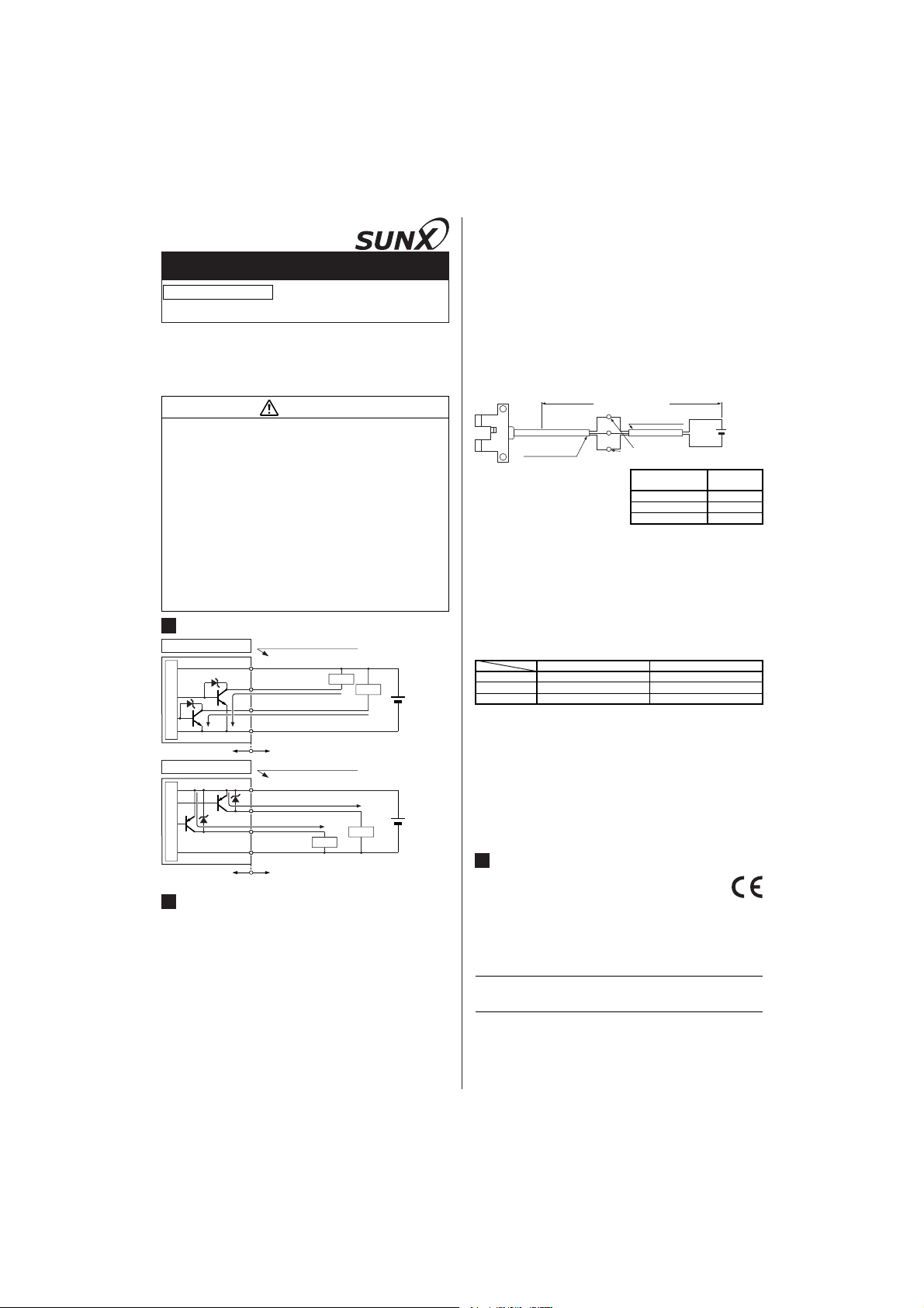
Cable extension is possible up to an overall length of
100m with a 0.3mm
a voltage drop shall occur due to the cable exten-
2
, or more, cable. However, since
sion, ensure that the power supply voltage at the end
of the cable attached to the sensor or at the sensor
terminals is within the rating.
Overall length: 100m
+V
Extension cable
Output
Connector
attached cable
But, when the overall cable length, including the
cable attached to the
sensor, is as given below, there is no need to
confirm the voltage.
٨
If there is a large surge generating equipment, such
0V
Supply voltage: 4.5V or more
Wire conductor
cross-section area
0.08 to 0.1mm2Up to 5m
0.2mm
0.3mm
2
2
㧗
5 to 24V DC
r10%
㧙
Overall cable
length
Up to 10m
Up to 20m
as, motor, solenoid, electromagnetic valve, etc., in
the vicinity of the micro-photosensor, use a surge absorber on that equipment. Further, do not run the
sensor cables along power lines and use a capacitor
between +V and 0V, if required. Use the sensor after
confirming that the surge has been eliminated.
٨
In case the sensor is fixed with screws, strictly observe the following conditions.
Screw M3
Tightening torque
Washer Ǿ6mm (small diameter type)
Note: If the ultra-small type PM-غ24(P), PM-غ24-R is used at an
ambient temperature of 50 or more, make sure to mount it on
a metallic body.
٨
Do not use during the initial transient time (50ms) after the power supply is switched on.
٨
The cable of PM-غ24-R is a flexible cable usable on
PM-غ24(P), PM-غ24-R
M2
0.15N㨯morless
Ǿ4.3mm (small diameter type)
PM-غ44(P), PM-غ54(P)
0.5N㨯morless
a moving base. When the sensor is mounted on a
moving base, fix the sensor cable joint so that stress
is not applied to it.
٨
Take care that the flexibility of the PM-غ24-R cable
is lost if the ambient temperature is near -10.
3
INTENDED PRODUCTS FOR CE MARKING
٨The models listed under 'Catalogue' come
with CE Marking.
As for all other models, please contact our
office.
SUNX Limited
Overseas Sales Dept. (Head Office)
2431-1 Ushiyama-cho, Kasugai-shi, Aichi, 486-0901, Japan
Phone: +81-(0)568-33-7861 FAX: +81-(0)568-33-8591
Europe Headquarter: Panasonic Electric Works Europe AG
Rudolf-Diesel-Ring 2, D-83607 Holzkirchen, Germany
Phone: +49-8024-648-0
US Headquarter: Panasonic Electric Works Corporation of America
629 Central Avenue New Providence, New Jersey 07974 USA
Phone: +1-908-464-3550
URL : sunx.jp
PRINTED IN JAPAN
 Loading...