

Panasonic PCF6W, PCV2, PCF2, PCV6W, PCF6 User Manual
...
Manufactured by:
81-IN3047-9922
Before attempting to connect or operate this product, please read these instructions completely.
for
MODEL: Miniature Camera
PCF2, PCV2, PCF6, PCV6,
PCF6W, PCV6W
DESCRIPTION: Dome Housing, Color Camera - PCF2, PCV2
Pendant Mount Dome Housing, Color Camera - PCF6, PCV6
Wall Mount Dome Housing, Color Camera - PCF6W, PCV6W
STANDARD INSTALLATION PROCEDURE
CONTENTS INCLUDE:
(1) Dome base
(1) Dome
(1) Dome liner
(1) Camera swivel plate
(1) Camera mount with camera, lens, and PC Board
(1) Camera adjustment arm
(1) Camera adjustment template
(2) 4-40 x 1/4" screws
(1) 8-32 x 3/8" screw
INSTALLATION
1. Locate the area on the ceiling or wall where the housing is
to be mounted. Cut a hole no larger than 2 1/4" in diameter and feed the necessary wires/cable through the hole.
2. Remove the dome and liner by turning the dome counterclockwise and gently pulling down.
3. Place the dome base against the ceiling/wall, with the
cutout in the center, and mark the keyhole slots. Insert a
screw on each mark and tighten down 3/4 of the length
of the screw.
4. Feed the wires/cable through the hole in the dome base.
5. Place the keyhole slots in the base over the screws and
slide forwared so that the screws hold the base to the surface. Tighten the screws.
PRODUCT INSTRUCTIONS
ATTACHING HOUSING (PCF6/PCV6 PENDANT MOUNT)
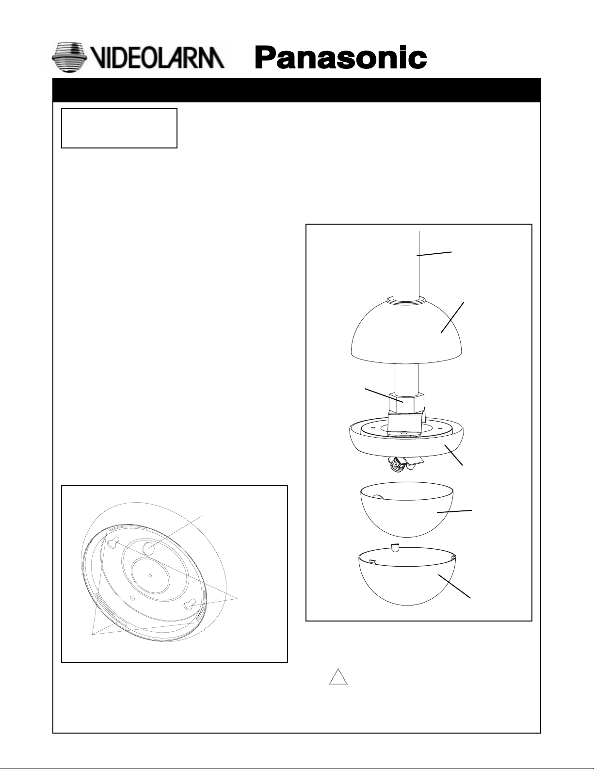
1. Install 3/4" EMT pipe (not provided) to the desired length.
2. Slide the top dome 10" to 12" onto the pipe, leaving enough
room to work. Run the wiring through the EMT connector
and wiring hole inside the top of the housing.
3. Slide complete unit onto the pipe. Tighten the set screw
when
in place.
4. Once the housing is secured to the pipe, slide the top dome
down onto the top of the housing.
3/4" EMT Pipe
(not provided)
Top Dome
EMT Clamp
Connector
Housing
Dome Tab Slots
Dome Tab Slots
Wire or Cable Entry
Wire or Cable Entry
Key Hole
Key Hole Slots
Slots
Liner
Dome
NOTE: Once the housing has been attached to the desired
location, connect the power and video wires as
required.
Connect Class 2 power supply only!
!
Camera swivel plate
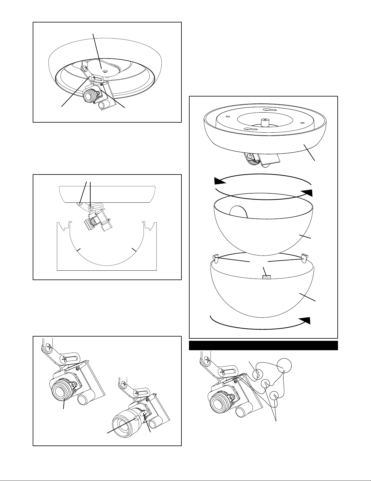
DOME REPLACEMENT
1. Rotate the liner inside the dome, so that when the dome is
secured to the base, the camera lens is in the center of the
viewing slot of the liner.
NOTE: It may be helpful to install the dome without the liner
the first time. This way you can visually determine
which direction the lens is pointing and adjust the liner
opening accordingly.
2. Align and insert the three tabs of the dome with the three tab
slots on the dome base. Rotate the dome clockwise until the
dome locks into place.
Camera Adjustment
Arm
CAMERA ADJUSTMENT
1. Clip the tabs of the template onto the swivel plate so that the
template is attached to the swivel plate.
2. Loosen the two 4-40 Phillips head screws, adjust the camera to
the desired position, and tighten the screws.
Note: Adjust camera lens as close as possible to the outline of
the bottom of the template.
Loosen screws to adjust camera
Tab
Place the lens as close to
this edge as possible
Camera Adjustment Template
3. Fine focusing (see diagram below):
Fixed Lens: Manually rotate the lens until a clear picture is
achieved.
Vari-Focal Lens: First, adjust the Magnification Lock Screw
to the desired magnification (telephoto
to wide angle). Tighten the Lock Screw.
Next, adjust the Focus Lock Screw until a
clear picture is achieved. Tighten the
Lock Screw.
Fixed Lens Camera
(PCF2, PCF6)
Camera Mount with
Camera and PC Board
Tab
Base
Liner
Tabs
Dome
Connections
Video
BNC Connectors
Manual focus
Focus Lock Screw
Vari-Focal Lens Camera
(PCV2, PCV6)
Magnification
Lock Screw
Power Connections
NOTE: Splice wiring according to
standard electrical guidlines.
Positive and Negative connections are
interchangeable with this PC Board.
- 2 -
 Loading...