

Panasonic NV-FJ610AR, NV-SJ410ARU, NV-SJ410AR, NV-FJ610ARU User Manual
NV-FJ610AR/ARU
NV-SJ410AR/ARU
Video Cassette Recorder
NV-FJ610AR/ARU
NV-SJ410AR/ARU
Operating Instructions
VQT9135
N-PAL NTSC
Before attempting to connect, operate or adjust this
product, please read these instructions completely.
Dear Customer
Thank you for purchasing this Panasonic Video
Cassette Recorder.
We strongly suggest that you carefully study
the Operating Instructions before attempting to
operate the VCR, and that you note the listed
precautions.
CVC (Crystal View Control)
Indicator
The crystal view control function ensures that
you always obtain the optimum picture quality
so that you get the best picture automatically.
While the VCR is turned on, the CVC indication
is always displayed to show that the Crystal
View Control is activated.
Longrun Head System
This longrun head system enables
approximately 8,000 hours of recording/
playback with high quality images. Newly
developed head cylinder with narrower head
windows and tapered cylinder design
effectively protects heads from dust and
prevents head clogging. Plus, “Alumina” Head
Cleaner further enhanced cleaning efficiency.
≥Based on in-house tests with Panasonic
video cassettes. Actual head life may vary
according to conditions of use, tape type,
temperature, humidity, etc.
The serial number of this product can be
found on the rear panel. No others have the
same serial number as yours. You should
record the number and other vital
information here and retain this book as a
permanent record of your purchase to aid
identification in case of theft.
Date of Purchase
Dealer purchased from
Dealer Address
Dealer Phone No.
Model No. NV-FJ610AR/ARU
NV-SJ410AR/ARU
Serial No.
Press POWER Í/I (POWER Í) to switch the
VCR from on to standby mode or vice versa. In
standby mode, the VCR is still connected to the
main AC power.
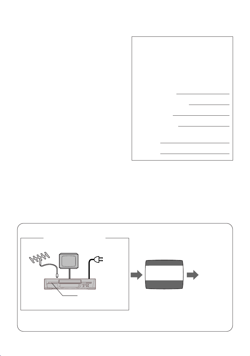
Plug in Auto Tuning
Setting image illustration
Antenna
1 Connect the
Antenna
cable.
All broadcasting stations that can be received in the area are automatically tuned and sored in
memory.
≥Do not turn off the VCR halfway. (See pages 13–16.)
2
TV
3 Press POWER
2 Connect the
AC power
cord.
Í/I button.
On Screen display
AUTO CHANNEL SET
PROCEEDING
END : MENU
2
Plug in Auto
Tuning is
completed.

Contents
As this equipment gets hot during use,
operate it in well ventilated place; do
not install this equipment in a confined
space such as a book case or similar
unit.
FOR YOUR SAFETY
∫ DO NOT REMOVE OUTER COVER.
To prevent electric shock, do not remove
cover.
No user serviceable parts inside. Refer
servicing to qualified service personnel.
WARNING
TO REDUCE THE RISK OF FIRE OR
SHOCK HAZARD, DO NOT EXPOSE THIS
EQUIPMENT TO RAIN OR MOISTURE.
IMPORTANT
Your attention is drawn to the fact that
recording of pre-recorded tapes or discs
or other published or broadcast material
may infringe copyright laws.
ACCESSORIES
1 pc. Infrared Remote Controller
1 pc. Coaxial Cable
2 pcs. “R6” size Batteries
Surge Absorber
For added protection for this product, these
models are equipped with new surge absorbing
circuit which prevents damage due to power
surges caused by induced lightning.
≥This function may not be effective for surges
by direct lightning.
Before Use
Controls and Connection Sockets ............ 04
Infra-red Remote Controller ....................... 06
Remote Controller Setup ............................ 09
Setting Up
Connections ................................................. 10
Tuning the TV to your VCR ........................ 13
≥Plug in Auto Tuning ................................. 13
Storing TV Broadcasts in your VCR .......... 15
Setting the Remote Controller for
Operation of your TV ............................... 17
Language Setting of the On Screen
Display ...................................................... 18
Setting the Clock of your VCR ................... 19
Settings Using the On Screen Display ...... 20
Basic Operations
Playback ....................................................... 25
≥Jet Search ............................................... 26
≥Other Playback Functions ....................... 26
Manual Recording ....................................... 28
≥One-Touch Recording (OTR) .................. 30
≥Direct Recording
(For NV-FJ610AR/ARU) .......................... 30
Advanced Operations
Timer Recording .......................................... 31
≥4-Key Programming ................................ 31
Search Functions ........................................ 34
≥Jet Navigator ........................................... 34
≥Time Stamp ............................................. 36
≥VHS Index Search System ..................... 37
≥Intro-Jet Scan .......................................... 37
Editing ........................................................... 38
≥Assembly Editing ..................................... 38
Other Functions ........................................... 39
≥Other Automatic Functions ..................... 39
Helpful Hints
Before Requesting Service ......................... 40
Usage Precautions ...................................... 42
Specifications ............................... Back cover
3
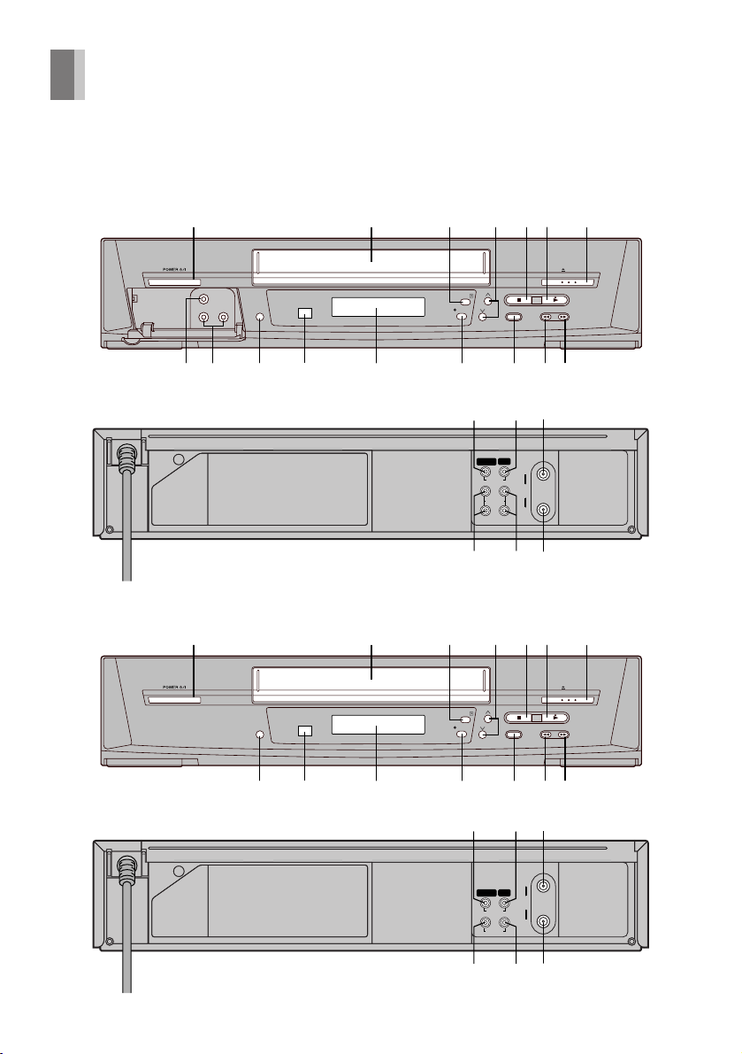
Controls and Connection Sockets
This section describes in detail the function of each button, switch and connection socket.
NV-FJ610AR/ARU
12
NV-SJ410AR/ARU
12
PICTURE MODE
PICTURE MODE
7
6
5
4
3
EJECT
CVC
111098
TIMER REC
REC/OTR
1312 14 15 16
STOP PLAY
SEARCH
65
/
REW FF
/
17 18 19
IN (AV1) OUT
IN
VIDEO
RF
L
AUDIO
R
OUT
2220 21
7
6
5
4
3
EJECT
CVC
TIMER REC
REC/OTR
STOP PLAY
SEARCH
65
/
REW FF
/
1110
1312 14 15 16
17 18 19
IN
IN (AV1) OUT
RF
VIDEO
OUT
AUDIO
2220 21
4
FRONT
01 POWER Í/I (POWER Í) (‘ 13)
02 Cassette Compartment (‘ 25)
03 TIMER REC Á (TIMER Á) (‘ 32)0
04 I J (‘ 14, 39)
05 STOP ∫ (‘ 25, 28)
06 PLAY 1 (‘ 25)
07 < EJECT (‘ 14)
08 VIDEO IN (AV2) (‘ 38)
(For NV-FJ610AR/ARU)
09 AUDIO IN (AV2) (‘ 38)
(For NV-FJ610AR/ARU)
10 PICTURE MODE (‘ 21, 27)
11 Infra-red Remote Control Receiver
Window
12 Display
13 ¥ REC/OTR (‘ 30)
14 SEARCH (‘ 37)
15 REW (REWIND) 6 (‘ 25)
16 FF (FAST FORWARD) 5(‘ 25)
REAR
17 VIDEO IN (AV1) (‘ 38)
18 VIDEO OUT (‘ 11)
19 RF IN (‘ 10)
20 AUDIO IN (AV1) (‘ 10, 38)
21 AUDIO OUT (‘ 10, 11)
22 RF OUT (‘ 10)
For NV-FJ610AR/ARU
14
POWER
1
SEARCH
MENU
6
DIRECT REC
Í
JET SEARCH
123
4
7809
AV
NAVI
5
INDEX
PICTURE MODE
6
100
5
VOLUME
+
–
INPUT SELECT
REC
10
6
15
§ Set VCR/TV switch to VCR for using
POWER Í, the I and J buttons.
For NV-SJ410AR/ARU
PICTURE MODE
1
10
6
;/D
15
OK
VCR
INDEX
3
1
OK
∫
4
ON OFF
SPEED
VOLUME
r
s
VCR/TV
AUDIO
9¥:
r
ON
s
s
TIMER
Á
VCR/TV
56
TV
W
X
W
X
REC
NAVI
TIMER
OFF
Á
r
s
1 2 3 4
rsrsr
DATE
CANCEL
PROG. / CHECK
AUDIO
RESET OSD/DISPLAY
TV
Í
AV
VCR
INPUT SELECT
Í
RESET
OSD/DISPLAY
MENU
2 1
PROG/CHECK SPEED
CANCEL
1 2 3 4
W
r
DATE
X
s
SEARCH
4
Before Use
16
5
§
3
4
16
5
14
3
5
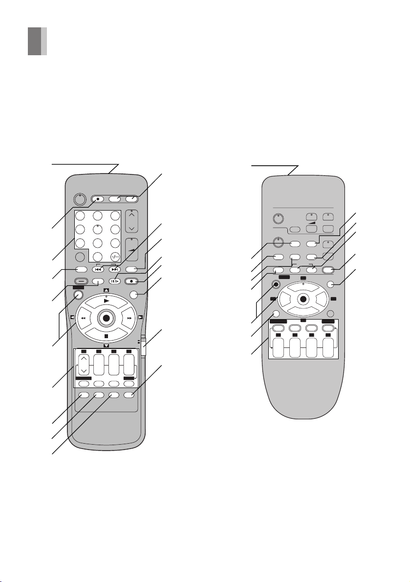
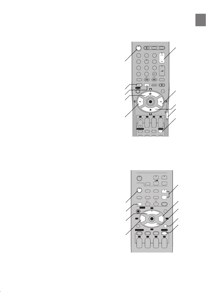
Infra-red Remote Controller
The remote control unit for this VCR is a universal remote controller. As such, some of its buttons are
not used to operate this VCR.
VCR OPERATION
For NV-SJ410AR/ARUFor NV-FJ610AR/ARU
1
1
11
POWER
Í
123
2
4
7809
3
4
AV
NAVI
SEARCH
MENU
5
6
PROG. / CHECK
7
AUDIO
6
DIRECT REC
JET SEARCH
6
5
100
INPUT SELECT
INDEX
PICTURE MODE
OK
1 2 3 4
rsrsr
DATE
ON OFF
CANCEL
SPEED
RESET OSD/DISPLAY
VOLUME
+
–
REC
VCR
s
TIMER
Á
VCR/TV
5
VOLUME
TV
12
13
14
15
16
13
10
9
5
17§
TV
6
14
7
Í
AV
VCR
INPUT SELECT
Í
RESET
OSD/DISPLAY
PICTURE MODE
MENU
2 1
;/D
PROG/CHECK SPEED
CANCEL
1 2 3 4
W
r
DATE
X
s
INDEX
3
1
OK
∫
4
r
s
VCR/TV
AUDIO
9¥:
r
ON
s
56
W
X
W
X
REC
NAVI
TIMER
Á
r
OFF
s
18
8
12
15
4
SEARCH
18
8
9
10
§ Set VCR/TV switch to VCR for using the
numeric buttons.
6
01 Infra-red Transmitter
14 ;/D (PAUSE/SLOW) (‘ 25)
02 DIRECT REC (‘ 30)
(For NV-FJ610AR/ARU)
03 Numeric Buttons (‘ 17, 28)
(For NV-FJ610AR/ARU)
Selects program positions of the VCR.
≥Ensure that VCR/TV switch is set to VCR.
0
9:
19:
109:
9
1
9
100
0
9
04 NAVI (‘ 34)
05 PICTURE MODE (‘ 21, 27)
06 On Screen Display Menu Operation
Buttons (‘ 15)
MENU
OK
3421
07 Timer Recording Operation Buttons
(‘ 31–33)
I J, DATE, ON, OFF
PROG./CHECK
CANCEL
SPEED
TIMER Á
15 REC ¥ (‘ 28)
16 No function
(For NV-FJ610AR/ARU)
This button is not used to operate this
VCR.
17 VCR/TV switch
(For NV-FJ610AR/ARU)
18 VCR/TV (‘ 13)
Before Use
08 AUDIO (‘ 21)
09 RESET (‘ 21)
10 OSD/DISPLAY (‘ 20, 29)
11 6 JET SEARCH 5 (‘ 26)
(For NV-FJ610AR/ARU)
12 INDEX :, 9 (‘ 37)
13 INPUT SELECT (‘ 38)
7
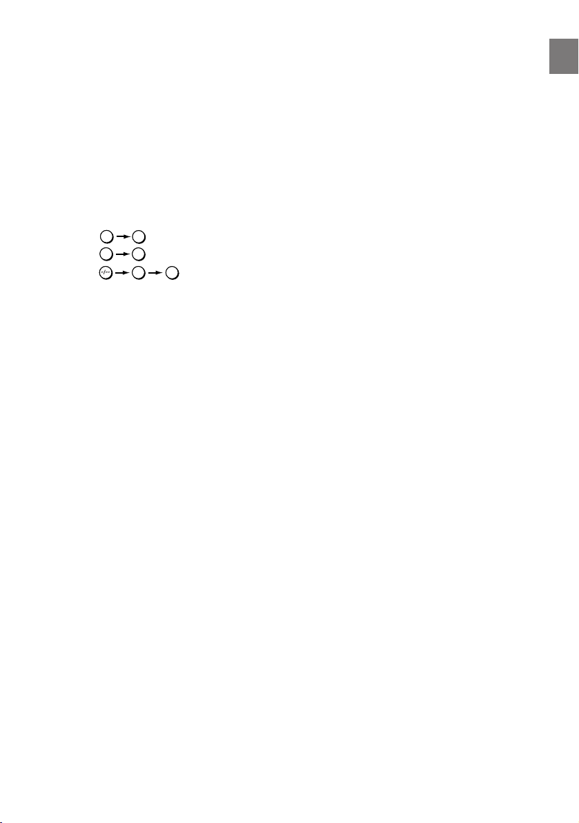
TV OPERATION
For NV-FJ610AR/ARU For NV-SJ410AR/ARU
(Panasonic TV only)
POWER
Í
DIRECT REC
6
JET SEARCH
5
123
19
20
21
4
7809
AV
NAVI
SEARCH
MENU
1 2 3 4
PROG. / CHECK
AUDIO
5
INDEX
PICTURE MODE
OK
rsrsr
DATE
ON OFF
CANCEL
SPEED
RESET OSD/DISPLAY
6
100
INPUT SELECT
TIMER
VCR/TV
VOLUME
+
–
REC
VCR
TV
s
Á
§ Set VCR/TV switch to TV for using POWER
Í, the I and J buttons and the numeric
buttons.
19 POWER Í
Press to switch the TV from on to standby
mode or vice versa. In standby mode, the
TV is still connected to the mains.
≥With some TV models, it may only be
possible to switch the TV to the standby
mode using this button.
In this case, use AV or the I and J
buttons to switch the TV on.
For NV-FJ610AR/ARU
≥Ensure that VCR/TV switch is set to TV.
8
§
22
23
VOLUME
AV
INPUT SELECT
VCR/TV
RESET
AUDIO
INDEX
9¥:
3
1
OK
∫
4
CANCEL
r
DATE
s
r
s
56
r
ON
s
Í
Í
MENU
1 2 3 4
W
X
W
X
REC
NAVI
TIMER
OFF
SEARCH
Á
r
s
19
OSD/DISPLAY
21
PICTURE MODE
2 1
;/D
PROG/CHECK SPEED
TV
VCR
W
X
20 Numeric Buttons
(For NV-FJ610AR/ARU)
Selects program positions of the TV.
≥Ensure that VCR/TV switch is set to TV.
21 AV
Selects TV input or AV input.
22 I J
Selects the required program position (TV
station) of the TV.
≥Ensure that VCR/TV switch is set to TV.
23 VOLUME sNr
Adjusts the volume of the TV.
23
22
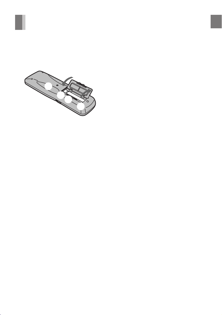
Remote Controller Setup
Installing the Batteries
Insert the batteries with the polarity (+ and -)
correctly aligned.
+
+
Power Source for the Remote Controller:
The remote controller is powered by 2 “AA”,
“UM3” or “R6” size batteries. The life of the
batteries is about one year, although this
depends on the frequency of use.
Precautions for Battery Replacement:
≥Load the new batteries with their polarity (+
and -) aligned correctly.
≥Do not apply heat to the batteries, or an
internal short circuit may occur.
≥If you do not intend to use the remote
controller for a long period of time, remove
the batteries and store them in a cool and dry
place.
≥Remove spent batteries immediately and
dispose of them.
≥Do not use an old and a new battery together,
and never use an alkaline battery with a
manganese battery.
≥Do not use rechargeable batteries.
Before Use
9
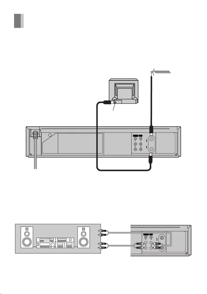
Connections
This section shows you how to connect the
VCR to an antenna, TV, etc.
When the VCR is turned on after connecting
the antenna cable and the AC power cord,
Plug in Auto Tuning starts automatically.
Basic Connections
The following connections are required to
record and play back the video cassette
through the TV.
2
TV Set (Not supplied)
Antenna Input Connector
IN (AV1) OUT
VIDEO
L
AUDIO
R
Antenna (Not supplied)
1
IN
RF
OUT
To mains supply
3
≥Connection to a Stereo Amplifier
(For NV-FJ610AR/ARU)
Stereo Amplifier
(Not supplied)
10
PLAYBACK
(Not supplied)
REC
IN (AV1) OUT
VIDEO
L
AUDIO
R
IN
RF
OUT
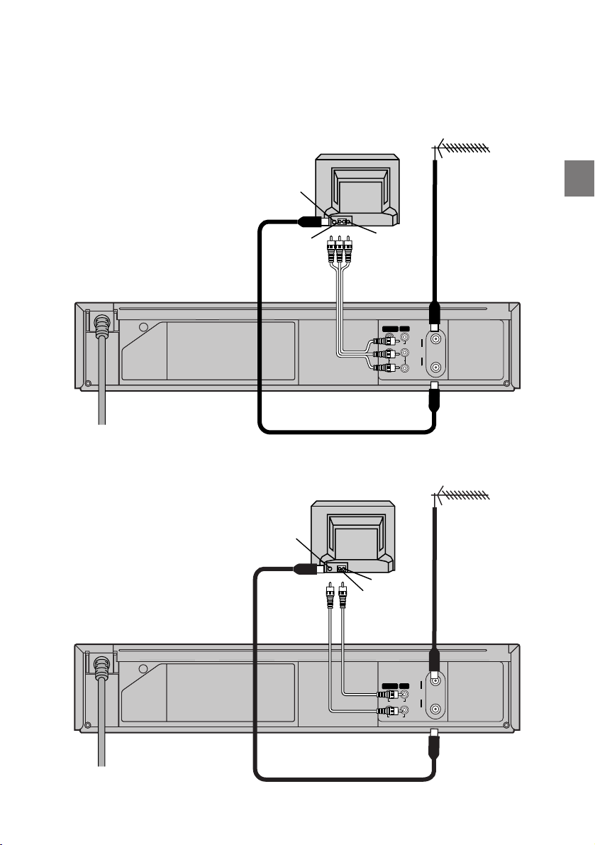
Connection to a TV using the Audio/Video Input Sockets
Antenna (Not supplied)
TV Set (Not supplied)
Antenna Input
Connector
1
NV-FJ610AR/ARU
4
To mains supply
NV-SJ410AR/ARU
AUDIO IN
2
Antenna Input
Connector
2
VIDEO IN
(Not supplied)
3
IN (AV1) OUT
VIDEO
L
AUDIO
R
TV Set (Not supplied)
VIDEO IN
AUDIO IN
3
(Not supplied)
Setting Up
IN
RF
OUT
Antenna (Not supplied)
1
4
To mains supply
IN (AV1) OUT
VIDEO
AUDIO
IN
RF
OUT
11
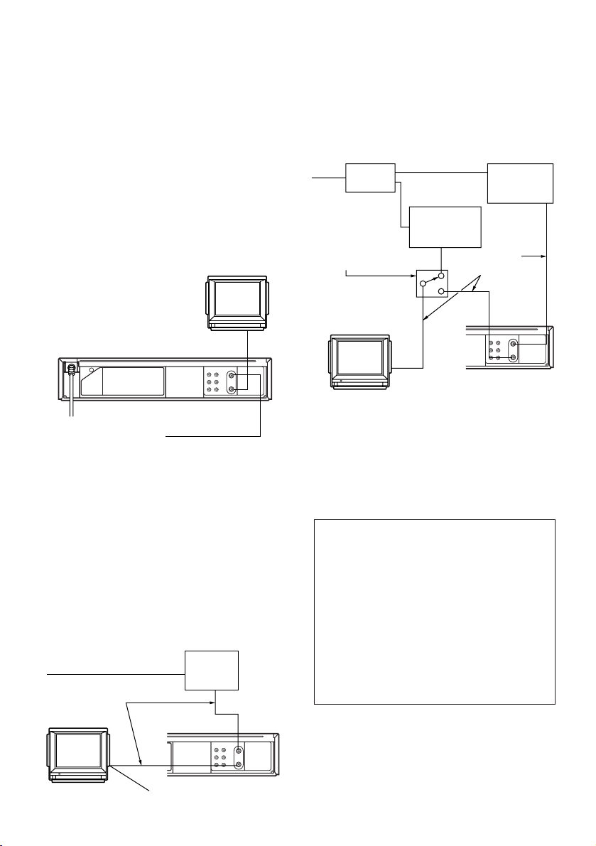
Cable Connection
Cable-VCR-TV (For CATV/PAY
Channels Recording/Playback)
The VCR has an extended range, and can tune
the Low-Band, Mid-Band, Super-Band, HyperBand, Ultra-Band, and Special cable channels
(Channels A-5–A-1, A – W, AA –FFF, GGG–
WWW, WWWr1–WWW r12, 100–125, 5A).
Also, the VCR can tune to any of the 56 UHF
channels (14– 69). Refer to Storing TV
Broadcasts in your VCR on page 15.
BASIC Hook-Up
Since the VCR can tune Mid
and Super Bands, this
connection will provide the
reception of all cable channels
except those which are
intentionally scrambled.
The cable hook-up shown at the bottom left
allows VCR-TV functions except for viewing
one channel while recording another.
75 ohm Cables System
2-WAY
SPLITTER
IN
OUT2
IN
Switch Box°
°Not available from
our company.
Please contact your
cable company.
To the 75 ohm VHF
Input on the TV set
OUT1 IN
Cable TV
Converter Box
75 ohm Coaxial
OUT
Cables
Cable TV
Converter Box
OUT
75 ohm Coaxial Cable
However, if you subscribe to a special channel
which is scrambled you will probably have a
descrambler box for proper reception. The VCR
by itself cannot properly receive a scrambled
program since it does not contain a
descrambler. In order for the VCR to properly
receive a scrambled program, your existing
descrambler must be used. There are two
commonly used methods of connection in this
case.
Typical Cable System Hook Ups
with Cable Converter/Descrambler
Boxes
75 ohm Cable System
75 ohm Coaxial
Cables
12
Cable TV
Converter
BoxIN
OUT
To the 75 ohm VHF
Input on the TV set
The above cable hook-up allows VCR
functions, including viewing one channel while
recording another, but it requires two cable TV
Converter/Descrambler Boxes, one Switch Box
and one 2-Way Splitter.
Since the VCR has an extended range of
tuning, tuning-programing of non-scrambled
Mid-Band and Super-Band TV programs is
possible. When a cable converter or
descrambler box is connected to the VCR,
all timer-controlled recording functions will
continue to operate with the exception of
charging channels automatically. CATV
Channel selection will have to be performed
with the cable converter. Timer-controlled
recording from CATV Channels is therefore
limited to one channel at any given time.
I
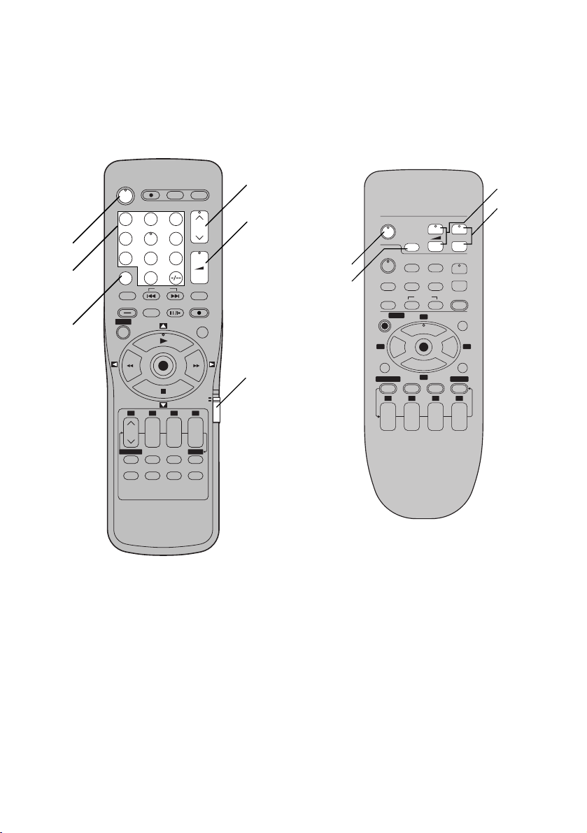
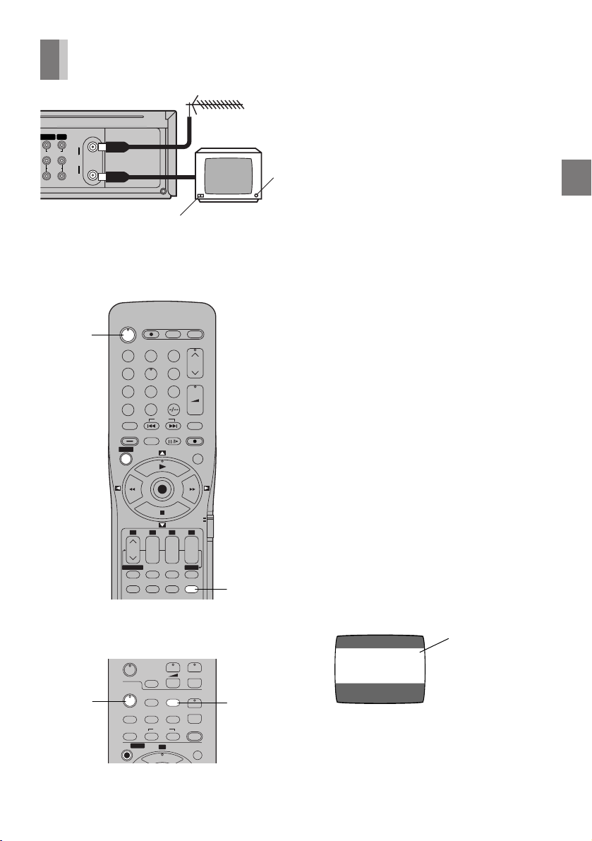
Tuning the TV to your VCR
TV
VOLUME
The VCR supplies a signal to the TV via the RF
coaxial cable on channel US3 or 4.
N (AV1) OUT
VIDEO
L
AUDIO
R
IN
RF
OUT
For NV-FJ610AR/ARU
POWER
DIRECT REC
1
Í
123
4
5
7809
AV
NAVI
SEARCH
PICTURE MODE
MENU
1 2 3 4
rsrsr
DATE
CANCEL
PROG. / CHECK
AUDIO
RESET OSD/DISPLAY
INDEX
OK
3
6
JET SEARCH
6
100
INPUT SELECT
ON OFF
SPEED
VOLUME
REC
VCR
s
TIMER
Á
VCR/TV
5
+
–
TV
2
It is possible to view the video picture on your
TV in the same way that you watch TV
broadcasts.
If you have connected the VCR to the TV
1
through the video and audio input sockets, then
you do not need to follow the procedure below.
When the VCR is turned on after unpacking
and connecting the antenna cable and the
AC power cord, Plug in Auto Tuning starts
automatically.
The VCR is fitted with its own tuner (just like a
normal TV) and can be preset to receive up to
181 TV broadcast stations.
Plug in Auto Tuning
Auto Tuning searches for TV stations from VHF
minimum to UHF maximum and memorizes
every tuned program position.
Notes:
≥If the VCR is turned on with the antenna not
connected, all channels are skipped.
≥When Auto Tuning is canceled halfway, Auto
Tuning is not executed even if the VCR is
turned off and then turned on again. In this
case, see page 14 “To Restart Plug in Auto
Tuning”.
1 Press POWER Í to turn on the TV and VCR
after connecting the antenna cable and the
AC power cord, Auto Tuning starts.
Setting Up
On Screen Display
For NV-SJ410AR/ARU
AUTO CHANNEL SET
W
r
Í
AV
X
INPUT SELECT
Í
RESET
MENU
INDEX
3
1
s
VCR/TV
AUDIO
9¥:
W
21
X
REC
NAVI
VCR
OSD/DISPLAY
PICTURE MODE
PROCEEDING
END : MENU
≥Auto Tuning will stop halfway by turning the
VCR off, pressing MENU, playback or a
power failure during Auto Tuning.
2
Channel being
searched
13
≥When there are 5 more CATV channels,
the antenna system CATV is automatically
selected; when there are 4 or fewer CATV
channels, the TV is selected. If a change is
required, conduct the resetting procedure
described in step 4 on page 15.
3 Disconnect the mains lead and then
reconnect it.
4 Turn off the VCR and then turn it on.
Press VCR/TV to select the VCR mode.
≥Auto Tuning commences.
2 Press VCR/TV to select the VCR mode.
3 Select a program number on the TV which
you wish to use as the video viewing
channel. Then tune in the TV to the picture
from the screen being auto tuned or the
screen selected with the I and J buttons
of the VCR.
≥During Auto Tuning, the TV program
screen does not appear, and the Auto
Tuning screen appears instead.
On Screen Display
AUTO CHANNEL SET
PROCEEDING
END : MENU
2
AUTO TUNING IS
COMPLETED.
END: MENU
To Cancel Auto Tuning MidOperation
Press MENU during Auto Tuning. Auto Tuning
is cancelled.
To Restart Plug in Auto Tuning
1 Press < EJECT and remove the video
cassette.
2 Keep the I and J buttons on the VCR
pressed simultaneously for 3 seconds or
more during the VCR on.
≥The channel displayed on the VCR display
disappears for a moment then changes to
2.
Display Symbol
Disappears 2
If Auto Tuning stops halfway by turning the
VCR off, playback or a power failure:
1 Disconnect the mains lead and then
reconnect it.
2 Turn off the VCR and then turn it on.
≥Auto Tuning commences.
To Change the RF Output
Channel
In some rare cases after tuning the TV to your
VCR, interference may be visible on the
picture. To get rid of this interference, you can
manually adjust the RF output channel a few
channels up and down from the current setting.
The procedure is described below.
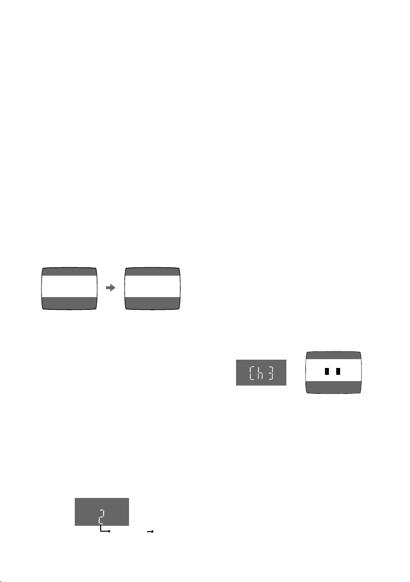
1 Hold down MENU for 5 seconds or more.
≥The VCR display changes as shown below
and the VCR picture on the TV displays
this pattern.
Panasonic VCR
END: MENU
2 Enter the desired channel number (US3 or
US4) by the I and J buttons.
3()4
3 Press MENU to finish the setting mode.
4 Retune your TV to the new RF channel for
the VCR.
Note:
≥Even if the RF output channel has been
changed, it is not necessary to perform Auto
Tuning.
14
 Loading...